KR101552919B1 - sealing apparatus of turbine with brush and method for manufacturing thereof - Google Patents
sealing apparatus of turbine with brush and method for manufacturing thereofDownload PDFInfo
- Publication number
- KR101552919B1 KR101552919B1KR1020150070629AKR20150070629AKR101552919B1KR 101552919 B1KR101552919 B1KR 101552919B1KR 1020150070629 AKR1020150070629 AKR 1020150070629AKR 20150070629 AKR20150070629 AKR 20150070629AKR 101552919 B1KR101552919 B1KR 101552919B1
- Authority
- KR
- South Korea
- Prior art keywords
- portions
- cover
- bristles
- sealing
- mounting
- Prior art date
- Legal status (The legal status is an assumption and is not a legal conclusion. Google has not performed a legal analysis and makes no representation as to the accuracy of the status listed.)
- Active
Links
Images


Classifications
- F—MECHANICAL ENGINEERING; LIGHTING; HEATING; WEAPONS; BLASTING
- F01—MACHINES OR ENGINES IN GENERAL; ENGINE PLANTS IN GENERAL; STEAM ENGINES
- F01D—NON-POSITIVE DISPLACEMENT MACHINES OR ENGINES, e.g. STEAM TURBINES
- F01D11/00—Preventing or minimising internal leakage of working-fluid, e.g. between stages
- F01D11/001—Preventing or minimising internal leakage of working-fluid, e.g. between stages for sealing space between stator blade and rotor
- F—MECHANICAL ENGINEERING; LIGHTING; HEATING; WEAPONS; BLASTING
- F01—MACHINES OR ENGINES IN GENERAL; ENGINE PLANTS IN GENERAL; STEAM ENGINES
- F01D—NON-POSITIVE DISPLACEMENT MACHINES OR ENGINES, e.g. STEAM TURBINES
- F01D11/00—Preventing or minimising internal leakage of working-fluid, e.g. between stages
- F01D11/08—Preventing or minimising internal leakage of working-fluid, e.g. between stages for sealing space between rotor blade tips and stator
- F—MECHANICAL ENGINEERING; LIGHTING; HEATING; WEAPONS; BLASTING
- F05—INDEXING SCHEMES RELATING TO ENGINES OR PUMPS IN VARIOUS SUBCLASSES OF CLASSES F01-F04
- F05D—INDEXING SCHEME FOR ASPECTS RELATING TO NON-POSITIVE-DISPLACEMENT MACHINES OR ENGINES, GAS-TURBINES OR JET-PROPULSION PLANTS
- F05D2240/00—Components
- F05D2240/55—Seals
- F05D2240/56—Brush seals
Landscapes
- Engineering & Computer Science (AREA)
- Mechanical Engineering (AREA)
- General Engineering & Computer Science (AREA)
- Turbine Rotor Nozzle Sealing (AREA)
Abstract
Translated fromKoreanDescription
Translated fromKorean본 발명은 터빈용 브러시 실링장치 및 그의 제조방법에 관한 것으로서, 보다 상세하게는 터빈 및 터빈 내부의 회전체 사이의 공간에 대한 실링 성능이 향상되되 제품의 생산성이 향상되는 터빈용 브러시 실링장치 및 그의 제조방법에 관한 것이다.The present invention relates to a brush sealing device for a turbine and a method of manufacturing the same, and more particularly, to a brush sealing device for a turbine which improves the productivity of a product between the turbine and a rotating body inside the turbine, And a manufacturing method thereof.
일반적으로, 터빈(turbine)은 물, 가스 혹은 증기 등의 유체가 가지는 에너지를 유용한 기계적 일로 변환시키는 기계를 말한다. 즉, 회전체의 원주를 따라 여러 개의 블레이드(blade)를 심고, 블레이드에 증기 또는 가스를 내뿜어 고속회전시키는 터보형의 기계를 터빈이라고 한다. 최근에는, 산업화 및 기술발전에 따라 증기터빈, 가스터빈과 같은 터빈이 점점 대형화, 고온화 및 고압화 되는 경향을 나타내고 있다.Generally speaking, a turbine is a machine that converts the energy of a fluid such as water, gas or steam into useful mechanical work. That is, a turbomachine is called a turbine in which a plurality of blades are planted along the circumference of the rotor, and the blades are sprayed with steam or gas and rotated at a high speed. In recent years, turbines such as steam turbines and gas turbines have become increasingly large-sized, high-temperature, and high-pressure due to industrialization and technological advancement.
이러한, 터빈에서 회전체와 고정된 케이싱 사이의 실링부로 누설되는 증기는 터빈의 효율을 저하시키고, 연료비용을 증가시키는 중요 요인이므로 증기 누설을 줄이기 위한 실링(Sealing) 장치의 설계기술은 매우 중요하다.Such leakage of steam from the turbine to the sealing portion between the rotating body and the fixed casing lowers the efficiency of the turbine and is an important factor for increasing the fuel cost. Therefore, a design technique of a sealing device for reducing steam leakage is very important .
여기서, 증기나 가스 터빈 같은 고온 및 고압 터빈에 사용되는 스테인리스 소재의 실링장치는 증가나 가스의 누설을 방지하여 발전기의 에너지 생산 효율을 상승시키고 유체로 인한 회전체의 진동방지에 중요한 역할을 한다.Here, a stainless steel sealing device used in high temperature and high pressure turbines such as steam or gas turbines increases the energy production efficiency of the generator by preventing an increase or leakage of gas, and plays an important role in preventing vibration of the rotating body due to fluid.
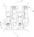
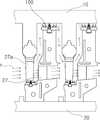
도 1은 종래의 래비린스형 실링장치가 터빈에 장착된 상태를 나타내는 단면도이고, 도 2는 종래의 래비린스형 실링장치를 나타낸 단면도이다.FIG. 1 is a sectional view showing a state where a conventional labyrinth type sealing apparatus is mounted on a turbine, and FIG. 2 is a sectional view showing a conventional labyrinth type sealing apparatus.
도 1 내지 도 2에서 보는 바와 같이, 종래의 래비린스형 실링장치(5)는 케이싱에 장착되어 있는 다이어프램(3)의 외부링과 내부링에 설치되어 있다.As shown in Figs. 1 and 2, the conventional labyrinth
여기서, 상기 래비린스형 실링장치(5)는 터빈의 비접촉식 환상 밀봉장치로 널리 사용되고 있으며, 날카로운 투쓰(6)로 터빈 내에서 흐르는 유체에 교축작용(throttling process)을 발생시켜 누설 유량을 감소시키는 것이다.The labyrinth
즉, 유체의 흐름에 따라 상기 투쓰(6)를 고정자에 차례로 배열하여 상기 유체가 교축과 확대를 반복하는 과정에서 발생하는 압력강하 효과에 의해 상기 유체의 누설유량을 감소시키게 된다.That is, the leakage flow rate of the fluid is reduced by the pressure drop effect generated in the process of arranging the
그러나, 종래의 상기 래비린스형 실링장치(5)를 이용하여 공간을 밀봉할 경우, 상기 로터부(1)와 상기 투쓰(6)의 간극으로 누설되는 상기 유체에 의해 효율 손실이 전체 터빈 효율 손실의 큰 비중을 차지한다.However, when sealing the space by using the conventional labyrinth
이때, 상기 투쓰(6)와 상기 로터부(1) 사이의 간극을 좁혀 유체 누설 손실을 줄일 수 있지만, 고가인 로터부(1)의 손상 방지를 위해 저경도로 구비된 투쓰(6)가 좁은 간극에 의해 압축된 유체에 의해 쉽게 변형되어 실링작용이 감퇴되는 문제점이 있었다.At this time, the gap between the
또한, 상기 투쓰(6)의 변형으로 인해 투쓰(6) 및 로터부(1) 사이의 간극이 분균일해지고, 불균일한 간극으로 유체가 유동됨에 따라 로터부(1)에 진동이 발생되어 회전력이 손실되고 내구성이 저하되는 문제점이 있었다.Further, due to the deformation of the
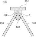
한편, 도 3은 종래의 브러시 실링장치를 나타낸 측면도이다.3 is a side view of a conventional brush sealing apparatus.
도 3에서 보는 바와 같이, 종래의 상기 브러시 실링장치는 회전체인 상기 로터부(1)와 고정된 케이싱(3) 사이 간극을 실링하는 브러시부(7)와 상기 브러시부(7)의 전방 및 후방을 지지하는 브리스틀 플레이트(8,9)를 포함한다.3, the conventional brush sealing apparatus includes a
여기서, 상기 브러시부(7)는 복수개의 브리스틀이 밀집된 형태로 구비되며, 고압 영역과 저압 영역을 분할하여 누설되는 유체의 흐름을 감소시킨다. 이때, 상기 각 브리스틀은 상단부가 고정된 상태에서 하단부가 상기 로터부(1)에 접촉하여 상기 유체를 실링함으로서 상기 래비린스형 실링장치에 비해 유체의 누출이 다소 저감될 수 있으며 각 브리스틀이 유연하게 휘어지며 상기 로터부(1)의 외주를 지지함에 따라 회전운동 손실량을 감소시키는 효과가 있다.Here, the
그러나, 종래의 브러시부(7)는 각각의 브리스틀이 상기 로터부의 외주에 직접 접촉하도록 구비되므로 로터부의 고속 회전시 마찰로 인해 회전방향을 따라 브리스틀이 당겨져 결합단부에 압력이 가해짐에 따라 브러시부(7)로부터 분리되는 경우가 많았다.However, since the
이에 따라, 분리된 브리스틀이 유체를 따라 유동되며 장치의 고장을 유발하는 문제점이 있었으며, 브리스틀의 밀집도가 저하하여 유체 실링 성능이 저하되는 문제점이 있었다.As a result, there is a problem that the separated bristles flow along the fluid and cause a failure of the apparatus, and the density of the bristles is lowered and the fluid sealing performance is deteriorated.
또한, 각각의 브리스틀이 미세한 직경으로 구비되므로 밀집된 형태로 고정시키는 작업이 힘들뿐만 아니라, 일정 이상의 밀집도를 갖도록 고정하기가 실질적으로 불가능한 문제점이 있었다.In addition, since each bristle is provided with a fine diameter, it is difficult to fix it in a dense form, and there is a problem that it is practically impossible to fix the bristles to have a density more than a certain level.
상기와 같은 문제점을 해결하기 위하여, 본 발명은 터빈 및 터빈 내부의 회전체 사이의 공간에 대한 실링 성능이 향상되되 제품의 생산성이 향상되는 터빈용 브러시 실링장치 및 그의 제조방법을 제공하는 것을 해결과제로 한다.In order to solve the above problems, the present invention provides a brush sealing apparatus for a turbine and a method of manufacturing the same that improve the productivity of a product with improved sealing performance against a space between the turbine and the rotating body inside the turbine .
상기의 과제를 해결하기 위하여, 본 발명은 터빈의 케이싱과 상기 케이싱의 내측에서 회전되는 회전체 사이로 유출되는 유체의 흐름을 실링하도록 상기 케이싱의 내주에 장착되는 실링부를 포함하는 터빈용 브러시 실링장치에 있어서, 상기 실링부에 장착되되, 한쌍으로 구비되어 각각의 상부에 체결수단에 의해 상호 체결되는 장착부가 구비되며, 결합된 내부에 장착공간이 형성되고, 각각의 하부에 상호 대향되는 방향으로 돌출된 가압부가 형성되는 커버부; 및 상기 장착공간의 상부에 배치되는 고정플레이트와, 상단부가 상기 고정플레이트의 하면에 고정되되 하단부가 상기 회전체의 외주측으로 연장되어 상기 각 가압부 사이를 통과하며 가압되도록 배치되는 복수개의 브리스틀을 포함하는 브러시부를 포함하되, 상기 고정플레이트의 하면에는 가이더부가 돌설되며, 상기 가이더부의 하단부에는 확장돌기부가 구비됨을 특징으로 하는 터빈용 브러시 실링장치를 제공한다.In order to solve the above problems, the present invention provides a brush sealing apparatus for a turbine including a sealing portion mounted on an inner circumference of a casing to seal a flow of fluid flowing between a casing of the turbine and a rotating body rotated from the inside of the casing The mounting part is mounted on the sealing part, and is provided with a pair of mounting parts which are fastened to each other by fastening means. The mounting space is formed inside the fastening part, and protruded in mutually opposite directions A cover portion in which a pressing portion is formed; And a plurality of bristles fixed to the lower surface of the fixing plate and having a lower end extending to an outer circumferential side of the rotating body and passing through between the pressing portions to be pressed, Wherein a guider part is provided on a lower surface of the fixing plate and an enlarged projection is provided on a lower end of the guider part.
여기서, 상기 고정플레이트의 하면 중앙부에는 가이더부가 돌설되되, 상기 가이더부의 하단부에는 전방 및 후방으로 분할된 상기 브리스틀 사이의 공간을 확장하는 확장돌기부가 구비되며, 상기 확장돌기부의 하부는 상기 가압부에 의한 측방향 가압시 상기 고정플레이트가 상기 장착부의 하면에 밀착되도록 상광하협의 형상으로 구비됨이 바람직하다.Here, the guiding portion is provided at the center of the lower surface of the fixing plate, and the lower end of the guiding portion is provided with an enlarging protrusion that expands a space between the front and rear bridges. The lower portion of the enlarging protrusion is press- So that the fixing plate is in close contact with the lower surface of the mounting portion.
삭제delete
또한, 상기 체결수단은 체결볼트 및 너트부재로 구비되고, 상기 각 장착부에는 상호 대향되는 부분을 따라 관통공이 형성되되, 상기 관통공의 테두리에는 상기 체결볼트의 헤드 및 상기 너트부재가 삽입되는 체결부삽입홈이 형성되며, 상기 장착부의 상단부에는 외측 테두리를 따라 슬라이드돌기부가 돌설되되, 상기 실링부에는 상기 장착부가 삽입되는 커버삽입홈부의 내측부를 따라 상기 슬라이드돌기부에 대응되는 슬라이드홈부가 형성됨이 바람직하다.In addition, the fastening means is provided with a fastening bolt and a nut member, and each of the fastening portions is provided with a through hole along the mutually opposed portion, and the fastening bolt head and the fastening portion A slide protrusion is formed along the outer edge of the upper end of the mounting portion and a slide groove portion corresponding to the slide protrusion is formed along the inner side of the cover insertion groove portion into which the mounting portion is inserted, .
한편, 하향 돌설된 가이더부가 구비된 고정플레이트의 하면을 따라 브리스틀의 상단부가 고정되되, 상기 고정된 브리스틀이 상기 가이더부에 밀착되도록 가압되어 전자빔 용접에 의해 고정되는 제1단계; 상기 브리스틀이 상기 가이더부의 하단부에 형성된 확장돌기부의 외면을 따라 밀착된 상태로 소성변형되도록 내측으로 가압되어 열처리되는 제2단계; 및 상기 고정플레이트가 한쌍으로 구비된 커버부의 내부에 배치되면 상기 각 커버부의 상부에 구비된 장착부가 체결수단에 의해 상호 체결되되, 상기 각 커버부의 내측부에 의해 상광하협의 형상으로 구비된 상기 확장돌기부의 하부가 가압되어 상기 고정플레이트가 상기 장착부에 밀착되고, 상기 각 커버부의 내측부 사이를 통과하도록 배치된 상기 브리스틀이 가압되는 제3단계를 포함하는 터빈용 브러시 실링장치의 제조방법을 제공한다.A first step in which the upper end of the bristle is fixed along the lower surface of the fixing plate having the downwardly protruding guider part, and the fixed bristle is pressed and fixed by the electron beam welding so as to be in close contact with the guider part; A second step in which the bristle is pressurized inward to be plastic-deformed in a state of being closely adhered along an outer surface of an extended projection formed at a lower end of the guider part; And the fixing plate is disposed inside the pair of cover parts, the mounting parts provided on the upper parts of the cover parts are fastened to each other by fastening means, and the extension projections And a third step in which the lower portion of the cover is pressed so that the fixing plate is brought into close contact with the mounting portion and the bristles arranged so as to pass between the inner side portions of the respective cover portions are pressed.
상기의 해결 수단을 통해서, 본 발명의 터빈용 브러시 실링장치 및 그의 제조방법은 다음과 같은 효과를 제공한다.Through the above solution, the brush sealing apparatus for a turbine of the present invention and its manufacturing method provide the following effects.
첫째, 상기 각 브리스틀의 고정된 상단부 배치 간격, 소재, 직경 등이 동일한 경우에도 가압부 사이를 통과하여 커버부의 결합시 내측으로 가압된 브리스틀이 한층 높은 밀집도로 압축되므로 브리스틀 사이의 틈을 통한 유체 누설이 최소화되되, 압축/밀집으로 향상된 지지력에 의해 회전 마찰/유체 압력에 따른 휘어짐 및 회전체와의 틈 발생이 최소화되어 제품의 실링 성능이 현저히 개선될 수 있다.First, even when the fixed upper end placement intervals, materials, diameters, etc. of the bristles are the same, the bristles pressed through the pressurizing portions and pressed inward during the engagement of the cover portions are compressed to a higher density, But the sealing performance of the product can be remarkably improved by minimizing the warping due to the rotational friction / fluid pressure and the occurrence of the gap with the rotating body due to the improved supporting force due to compression / compactness.
둘째, 상기 브리스틀은 상단부가 고정플레이트에 고정되되, 가이더부의 하단부에 확장 형성된 확장돌기부를 감싸며 휘어져 가압부의 상단부에 걸린 상태에서 가압부 사이를 통과하며 가압되므로 용접, 걸림, 가압에 의해 다단계로 견고하게 고정되어 고압 유체 및 회전 마찰에 따른 분리가 최소화되어 제품의 내구성이 향상될 수 있다.Second, the bristle is fixed to the fixed plate at the upper end, and the expanded protruding portion extended at the lower end of the guider portion is bent to be bent at the upper end of the pressing portion, and passes through between the pressing portions to be pressed. So that the separation due to the high-pressure fluid and the rotational friction can be minimized and the durability of the product can be improved.
셋째, 상기 확장돌기부의 하부는 상광하협의 형상으로 구비되어 커버부의 결합시 가압부 내지 브리스틀에 의한 측방향 압력을 상측 방향으로 전환하므로 별도의 고정 수단 없이도 고정플레이트가 장착부의 하면에 밀착 고정될 수 있어 브러시부의 분리 및 교체가 용이하여 제품의 사용편의성이 향상될 수 있다.Third, since the lower portion of the enlarged projection is formed in an upper light-tight shape, the lateral pressure of the pressing portion or the bristle is shifted upward when the cover portion is engaged, so that the fixing plate is tightly fixed to the lower surface of the mounting portion And the brush part can be easily separated and replaced, so that the usability of the product can be improved.
넷째, 상기 확장돌기부를 거쳐 하부로 연장된 브리스틀이 열처리에 의해 라운드지게 소성변형되어 상호 접촉된 상태에서 커버부의 내부에 배치되고 가압부에 의해 가압되므로 커버부의 체결공정이 용이하게 이루어질 뿐만 아니라, 소성 변형으로 브리스틀의 하단부가 정렬된 상태에서 가압되므로 급격한 변형에 의한 흐트러짐이 최소화될 수 있다.Fourthly, since the bristles extending downward through the extended projections are plastic-deformed roundly by heat treatment and disposed inside the cover part in a mutual contact state, the bristles are pressed by the pressurizing part, so that the fastening process of the cover part is not only easy, Since the lower end of the bristle is pressurized in an aligned state due to plastic deformation, disturbance due to abrupt deformation can be minimized.
도 1은 종래의 래비린스형 실링장치가 터빈에 장착된 상태를 나타내는 단면도.
도 2는 종래의 래비린스형 실링장치를 나타낸 측단면도.
도 3는 종래의 브러시 실링장치를 나타낸 측단면도.
도 4는 본 발명의 일실시예에 따른 터빈용 브러시 실링장치가 터빈에 장착된 상태를 나타낸 단면도.
도 5는 본 발명의 일실시예에 따른 터빈용 브러시 실링장치를 나타낸 측면도.
도 6, 도 7, 도 8 및 도 9는 본 발명의 일실시예에 따른 터빈용 브러시 실링장치의 제조방법을 나타낸 예시도.
도 10은 본 발명의 다른 실시예에 따른 터빈용 브러시 실링장치를 나타낸 측면도.1 is a cross-sectional view showing a state where a conventional labyrinth type sealing device is mounted on a turbine.
2 is a side sectional view showing a conventional labyrinth type sealing apparatus.
3 is a side cross-sectional view of a conventional brush seal device;
4 is a cross-sectional view of a turbine brush sealing device mounted on a turbine according to an embodiment of the present invention.
5 is a side view of a brush sealing apparatus for a turbine according to an embodiment of the present invention.
6, 7, 8, and 9 are views illustrating a method of manufacturing a brush seal apparatus for a turbine according to an embodiment of the present invention.
10 is a side view of a brush sealing apparatus for a turbine according to another embodiment of the present invention.
이하, 첨부된 도면을 참조하여 본 발명의 바람직한 실시예에 따른 터빈용 브러시 실링장치를 상세히 설명한다.Hereinafter, a brush sealing apparatus for a turbine according to a preferred embodiment of the present invention will be described in detail with reference to the accompanying drawings.
도 4는 본 발명의 일실시예에 따른 터빈용 브러시 실링장치가 터빈에 장착된 상태를 나타낸 단면도이다.4 is a cross-sectional view illustrating a state in which a turbine brush sealing apparatus according to an embodiment of the present invention is mounted on a turbine.
도 4에서 보는 바와 같이, 본 발명의 일실시예에 따른 터빈용 하이브리드 브러시 실링장치(100)는 터빈의 케이싱(20)과 회전체(10) 사이로 누출되는 유체(f)의 흐름을 실링하도록 장착될 수 있다.4, the hybrid
여기서, 상기 회전체(10)는 외주를 따라 복수개의 블레이드(27a)가 결합된 로터부를 포함하는 개념으로 이해함이 바람직하다. 이때, 상기 브러시 실링장치(100)는 링 형상으로 구비되어 회전체(10)의 외주 및 케이싱(20)의 내주 사이에 원주방향을 따라 배치될 수 있다.Here, it is preferable that the
여기서, 유체(f)의 흐름을 실링한다는 말은 회전체(10)의 회전이 원활하게 이루어지도록 회전체(10)의 블레이드 전방의 고압 영역과 블레이드 후방의 저압 영역을 구획하되, 고압 영역 유체의 압력을 감소시킨 후 저압 영역으로 유동시킨다는 의미로 이해함이 바람직하다.The term sealing the flow of the fluid f means to divide the high pressure area in front of the blade of the rotating
물론, 상기 브러시 실링장치(100)는 상기 케이싱(20)과 상기 블레이드(27a)의 단부 사이, 상기 케이싱(20)과 싱기 로터부의 원통형 몸체부 사이에 배치되어 유체의 누설 흐름을 감소시킬 수 있으며, 상기 케이싱 내부에서 회전되는 회전체(20)와 고정된 상기 케이싱(10) 사이에서 실링이 필요한 모든 장소에 장착될 수 있다.Of course, the
도 4에 도시된 화살표와 같이, 상기 케이싱(20) 내로 유입된 증기 또는 가스 등의 유체(f)는 케이싱(20)에 고정된 다이아프램의 파티션(27)을 통과하며 상기 로터부에 구비된 블레이드(27a)를 회전시킨다. 그리고, 상기 유체(f)는 다시 파티션(27)의 안내에 따라 다음 블레이드를 회전시키는 단계를 거치며 외부로 배출되게 된다.4, the fluid f such as steam or gas introduced into the
이러한 과정을 통해, 발전기는 각 블레이드(27a)와 함께 회전되는 로터부를 통해 회전력을 전달받고, 회전력을 전기적 에너지로 변환하여 발전이 이루어질 수 있다.Through this process, the generator receives the rotational force through the rotor portion rotated together with each of the
도 5는 본 발명의 일실시예에 따른 터빈용 브러시 실링장치를 나타낸 측면도이며, 도 6, 도 7, 도 8 및 도 9는 본 발명의 일실시예에 따른 터빈용 브러시 실링장치의 제조방법을 나타낸 예시도이다.FIG. 5 is a side view illustrating a turbine brush sealing apparatus according to an embodiment of the present invention, and FIGS. 6, 7, 8, and 9 are views showing a method of manufacturing a brush sealing apparatus for a turbine according to an embodiment of the present invention. Fig.
도 5 내지 도 9를 참조하면, 상기 터빈용 브러시 실링장치(100)는 실링부(110), 커버부(120), 그리고 브러시부(130)를 포함한다.5 to 9, the
여기서, 상기 실링부(110)는 터빈의 케이싱(20)과 상기 케이싱(20)의 내측에서 회전되는 회전체(10) 사이로 유동되는 유체의 흐름을 실링하도록 상기 케이싱(20)의 내주에 결합된다.The sealing
상세히, 상기 실링부(110)는 링 형상으로 구비되어 상기 회전체(10)의 외주와 상기 케이싱(20)의 내주 사이를 원주방향으로 커버하여 실링할 수 있다.In detail, the
이때, 상기 실링부(110)는 완전한 링 형상으로 구비될 수도 있으나, 장착 편의성을 위해 일정한 각도로 분할되도록 구비될 수 있으며, 조립시 완전한 링 형상을 이루어 상기 케이싱(20)의 내주와 상기 회전체(10)의 외주 사이의 공간을 커버할 수 있다.At this time, the sealing
또한, 상기 케이싱(20)의 내주에는 상기 실링부(110)의 장착을 위한 결합홈(21)이 형성되며, 상기 실링부(110)의 상부에는 상기 결합홈(21)과 대응되는 형상의 결합돌기(111)가 형성될 수 있다.A
이때, 상기 결합홈(21)과 상기 결합돌기(111) 사이에는 탄성부재(140)가 구비됨이 바람직하며, 상기 실링부(110)의 결합돌기(111)는 상기 탄성부재(140)에 의해 반경방향 내측으로 탄발지지될 수 있다.At this time, it is preferable that an
이에 따라, 상기 실링부(110)에 브러시부(130)가 탄성부재(140)의 가압력에 의해 상기 회전체(10)에 인접한 상태를 유지하되, 상기 회전체(10)가 진동 및 팽창 등으로 인해 상기 브러시부(130)와 접촉하여 탄성부재(140)의 가압력 이상의 힘을 가하면 상기 실링부(110)가 반경방향 외측으로 이동되어 브러시부(130)의 과도한 접촉 및 마모를 최소화할 수 있다.Accordingly, the
이때, 상기 실링부(110)에는 커버부(120)가 장착되고, 상기 커버부(120)의 내부에는 브러시부(130)가 구비될 수 있다. 여기서, 상기 실링부(110)는 상기 터빈의 케이싱(20)과 상기 커버부(120)를 매개하는 역할을 하며, 상기 커버부(120)의 상부에 결합돌기(111)와 대응되는 부분이 구비되는 경우에는 상기 커버부(120)가 상기 케이싱(20)에 직접 결합되는 것도 가능하다.At this time, a
한편, 상기 커버부(120)는 실링부(110)에 장착되되, 한쌍으로 구비되어 각각의 상부에 체결수단(b,n)에 의해 상호 체결되는 장착부(123,124)가 구비되며, 결합된 내부에 장착공간(k)이 형성되고, 각각의 하부에 상호 대향되는 방향으로 돌출된 가압부(121,122)가 형성된다.The
이때, 상기 각 커버부(120a,120b)는 상호 대칭되는 형상으로 구비될 수 있으며, 각 커버부(120a,120b)의 상부에는 장착부(123,124)가 형성되고, 각 커버부(120a,120b)의 하부에는 가압부(121,122)가 형성될 수 있다.In this case, the
그리고, 상기 장착부(123,124) 및 상기 가압부(121,122)를 연결하는 부분에는 장착홈부(120c,120d)가 형성될 수 있다. 이때, 상기 장착홈부(120c,120d)는 전방 커버부(120a) 및 후방 커버부(120b)가 상호 대면되는 부분을 따라 형성됨이 바람직하다.The mounting
즉, 전방 커버부(120a)는 후방에 장착홈부(120c)가 형성되고, 후방 커버부(120b)는 전방에 장착홈부(120d)가 형성되며, 각 장착홈부(120c,120d)에 의해 장착공간(k)이 형성될 수 있다.That is, the
그리고, 상기 가압부(121,122)는 상기 각 커버부(120a,120b)가 대향되는 방향으로 돌출되며, 전방 커버부(120a)의 가압부(121)는 후방으로 돌출되도록 형성되고, 후방 커버부(120b)의 가압부(122)는 전방으로 돌출되도록 구비될 수 있다.The
이때, 상기 각 가압부(121,122)는 상기 각 커버부(120a,120b)의 결합시 각각의 단부가 상호 이격되도록 구비됨이 바람직하며, 상기 각 커버부(120a,120b)의 결합시 상기 가압부(121,122) 사이에 상기 장착공간(k)에 배치된 브러시부(130)의 브리스틀(138,139)이 통과할 수 있는 공간이 형성될 수 있다.At this time, the
그리고, 상기 커버부(120a,120b)는 링 형상으로 구비될 수 있으며, 상기 회전체(10)의 외주 및 상기 실링부(110)의 내주 사이를 원주방향으로 커버할 수 있다.The
이때, 상기 커버부(120a,120b)는 실링부(110)와 동일하게 완전한 링 형상으로 구비될 수 있으며, 조립시 완전한 링 형상을 이루도록 일정한 각도로 분할되어 구비될 수 있다. 물론, 상기 실링부(110) 및 상기 커버부(120a,120b)가 분할되는 각도는 상이하게 설정될 수 있다.At this time, the
한편, 상기 브러시부(130)는 고정플레이트(131)와 브리스틀(138,139)을 포함한다. 여기서, 상기 고정플레이트(131)는 상기 장착공간(k)의 상부에 배치되며, 상기 고정플레이트(131)의 하면에는 가이더부(132)가 돌설된다.The
이때, 상기 가이더부(132)는 상기 고정플레이트(131)의 하면 중앙부에 돌설될 수 있으며, 상기 브리스틀(138,139)은 가이더부(132)에 의해 구획되어 고정플레이트(131)의 하면 전방부 및 후방부에 고정될 수 있다.The guiding
즉, 상기 고정플레이트(131)는 단면이 T자형을 이루도록 구비되며, 상기 커버부(120) 내지 실링부(110)와 동일하게 완전한 링 형상으로 구비되거나 조립시 완전한 링 형상을 이루도록 일정한 각도로 분할되어 구비될 수 있다.That is, the fixing
여기서, 상기 실링부(110) 및 상기 커버부(120), 상기 고정플레이트(131)는 원심주조에 의해 제조됨이 바람직하다. 이에 따라, 완전한 링 형상 내지 분할된 링 형상으로 구비된 실링부(110), 커버부(120), 고정플레이트(131)가 정확한 형상으로 주조될 수 있다.Here, the sealing
즉, 상기 실링부(110)는 상기 케이싱(20)의 내주에 대응되도록 제조될 수 있으며, 상기 커버부(120)는 상기 실링부(110)의 내주에 대응되도록 제조되고, 상기 고정플레이트(131)는 상기 커버부(120)의 장착부(123,124) 하면에 대응되도록 제조될 수 있다. 이에 따라, 각각의 접촉면이 정확하게 형합될 수 있어 제품의 실링성능이 개선될 수 있다.That is, the sealing
그리고, 상기 고정플레이트(131)의 전단 및 후단 사이의 간격은 상기 각 커버부(120a,120b)의 결합시 형성된 장착공간(k) 전후 방향 간격에 대응하여 구비됨이 바람직하다.The spacing between the front end and the rear end of the fixing
이에 따라, 상기 고정플레이트(131)가 상기 장착공간(k) 내부에서 전방 및 후방으로 유동되지 않고 정확한 위치에 고정되어 상기 브리스틀(138,139)이 비틀어지지 않고 상기 회전체(10)의 외주를 정확하게 실링할 수 있다.Accordingly, the fixing
즉, 상기 고정플레이트(131)의 상면은 상기 장착부(123,124)의 하면에 접하도록 배치되며, 상기 고정플레이트(131)의 전단 및 후단은 상기 각 커버부(120a,120b)의 장착홈부(120c,120d) 내측면에 접하도록 배치될 수 있다.That is, the upper surface of the fixing
여기서, 장착홈부(120c,120d)의 내측면이라는 말은 상기 각 장착홈부(120c,120d)에서 타측 장착홈부와 마주보는 면을 의미하며, 전방 커버부(120a)의 후면에 대응되는 면과, 후방 커버부(120b)의 전면에 대응되는 면으로 이해할 수 있다.The inner surface of the mounting
또한, 상기 브리스틀(138,139)은 복수개로 구비되어 상단부가 상기 고정플레이트(131) 하면에 고정되되 하단부가 상기 회전체(10)의 외주측으로 연장되어 상기 각 가압부(121,122) 사이를 통과하며 가압되도록 배치된다.The upper and lower ends of the
여기서, 상기 각 브리스틀(138,139)은 탄성력과 내열성을 가진 유연한 소재로 구비될 수 있으며, 얇은 섬유의 형태로 구비될 수 있다. 이때, 상기 각 브리스틀(138,139)의 상단부는 전자 빔 용접(Electric beam welding, EBW)이나 고온에 안정한 접착물질에 의해 고정될 수 있다.Here, each of the
상세히, 상기 브리스틀(138,139)은 가이더부(132)에 의해 구획된 고정플레이트(131)의 하면 전방부(134) 및 하면 후방부(135)를 따라 고정되며, 상기 가이더부(132)에 의해 전방(138) 및 후방(139)으로 분할될 수 있다.Specifically, the
그리고, 상기 브리스틀(138,139)은 하단부가 상기 회전체(10)의 외주측으로 연장되어 상기 각 가압부(121,122) 사이의 공간을 통과하되, 상기 각 커버부(120a,120b)의 결합시 상기 각 가압부(121,122)에 의해 내측으로 가압될 수 있다.The lower ends of the
여기서, 상기 브리스틀(138,139)의 상단부가 고정된 면적은 상기 가압부(121,122) 사이의 공간보다 넓게 구비됨이 바람직하다. 즉, 넓은 단면적을 따라 고정된 각 브리스틀은 가압부(121,122)의 공간에서 가압되어 압축되며, 높은 밀집도를 가지게 된다.Here, it is preferable that an area where the upper ends of the
이에 따라, 상기 각 브리스틀(138,139)의 고정된 상단부 배치 간격, 소재, 직경 등이 동일한 경우에도 상기 가이더부(132)의 전방측에 고정된 전방 브리스틀(138) 및 후방측에 고정된 후방 브리스틀(139)이 상기 가압부(121,122) 사이의 공간을 통과하며 모아져 각 커버부(120a,120b)의 결합시 상기 각 가압부(121,122)에 의해 내측으로 가압됨에 따라 매우 높은 밀집도로 압축될 수 있다.Accordingly, even when the
따라서, 하나의 브리스틀과 인접한 다른 브리스틀 사이의 틈을 통한 유체 누설이 최소화될 수 있으며 제품의 실링성능이 개선될 수 있다.Thus, fluid leakage through a gap between one Bristol and another adjacent Bristol can be minimized and the sealing performance of the product can be improved.
또한, 밀집/압축된 브리스틀이 인접한 다른 브리스틀을 지지하며 높은 지지력을 형성하므로 회전 마찰/유체 압력에 따른 휘어짐과 휘어짐에 따른 회전체(10)와의 틈 발생이 최소화될 수 있어 제품의 실링 성능이 현저히 개선될 수 있다.In addition, since the dense / compressed bristles support other bristles adjacent to each other and form a high supporting force, the occurrence of gaps with the rotating
한편, 상기 가이더부(132)의 하단부에는 상기 브리스틀(138,139)을 전방 내지 후방으로 가압하도록 돌설된 확장돌기부(133)가 구비됨이 바람직하다.It is preferable that the
즉, 상기 확장돌기부(133)는 상기 가이더부(132)에 의해 전방 및 후방으로 분할된 전방측 브리스틀(138) 및 후방측 브리스틀(139) 사이의 공간을 확장시킬 수 있다.That is, the
이때, 상기 확장돌기부(133)는 상기 가이더부(132)의 전방 및 후방 양측을 가압하도록 전방 및 후방 양측으로 돌출되어 구비될 수 있다.At this time, the
그리고, 상기 확장돌기부(133)는 상기 장착공간(k) 내부에 배치되며, 상기 가압부(121,122) 사이의 공간 상부측에 인접하도록 구비될 수 있다. 이때, 상기 확장돌기부(133)는 상기 가압부(121,122) 사이의 공간을 통해 상기 커버부(120)의 하부로 이탈되지 않도록 상기 각 커버부(120)의 결합시 상기 각 가압부(121,122) 단부 사이의 간격보다 넓은 폭을 갖는 것이 바람직하다.The
상세히, 상기 각 브리스틀(138,139)은 상기 고정플레이트(131)의 하면에 고정되되, 상기 가이더부(132)에 의해 전방 및 후방으로 분할된다.Specifically, each of the
그리고, 상기 브리스틀(138,139)은 상기 확장돌기부(133)의 외면을 거치며 넓게 벌어진 후 내측으로 모아진 상태로 상기 가압부(121,122) 사이의 공간을 통과하게 된다.The
이때, 상기 확장돌기부(133)의 전후방 폭이 상기 가압부(121,122) 사이의 공간보다 넓게 형성되므로 상기 브리스틀(138,139)은 상기 확장돌기부(133)의 외면을 감싸며 전방 내지 후방으로 라운드지게 휘어져 상기 가압부(121,122) 사이를 통과하게 된다.Since the front and rear widths of the
즉, 상기 전방측 브리스틀(138)은 전방측으로 라운드지게 휘어지고, 상기 후방측 브리스틀(139)은 후방측으로 라운드지게 휘어진 상태에서 상기 가압부(121,122)를 통과하게 되며, 라운드지게 휘어진 부분이 상기 가압부(121,122)의 상단부에 걸리고, 상기 확장돌기부(133)의 하면부에 의해 가압부(121,122)의 상단부로 가압되어 고정될 수 있다.That is, the front side bristle 138 is roundly bent forward, and the rear side bristle 139 passes through the
그리고, 상기 전후방으로 분할된 브리스틀(138,139)은 내측으로 모아져 상기 가압부(121,122)를 통과하되 상기 각 커버부(120a,120b)의 상호 결합에 따라 상기 각 가압부(121,122) 사이에서 가압될 수 있다.The front and
이처럼, 상기 브리스틀(138,139)이 상기 고정플레이트(131)에 고정되되, 상기 확장돌기부(133)를 감싸며 휘어져 가압부(121,122)의 상단부에 걸린 상태에서 가압부(121,122) 사이에 가압 고정된다.The
이에 따라, 브리스틀(138,139)이 고정플레이트(131)와의 용접 내지 접착, 확장돌기부(133) 및 가압부(121,122)를 통한 걸림 고정, 가압 고정 등에 의해 다단계로 고정되므로 유체의 압력 및 회전 마찰로 인해 당김힘이 가해지는 경우에도 고정플레이트(131)로부터 분리가 최소화될 수 있어 제품의 내구성이 향상될 수 있다.Accordingly, since the
더욱이, 상기 브리스틀(138,139)은 확장돌기부(133)에 의해 가압부(121,122)의 상단부에 걸린 상태에서 가압부(121,122) 사이에서의 가압되므로 인접한 브리스틀 사이의 마찰력이 극대화되어 회전마찰 내지는 유체의 압력을 통해 브리스틀(138,139)에 가해지는 압력 하나의 브리스틀에 가해지는 것이 아니라 브리스틀 전체로 분산되므로 브리스틀의 고정력이 현저히 향상될 수 있다.Further, since the
한편, 상기 확장돌기부(133)의 하부는 상기 커버부의 내측부에 의한 측방향 가압시 상기 고정플레이트(131)가 상기 장착부(123,124)의 하면에 밀착되도록 상광하협의 형상으로 구비됨이 바람직하다.It is preferable that the lower portion of the
여기서, 상기 커버부의 내측부는 상호 대향되는 방향으로 돌설된 상기 가압부(121,122)로 이해할 수 있다.Here, the inner side portion of the cover portion can be understood as the
즉, 상기 확장돌기부(133)의 하부는 상기 커버부의 결합시 가압부(122,122)에 의한 측방향 가압으로 상측으로 이동되도록 상광하협의 형상으로 구비되며, 상기 확장돌기부(133)의 상측 방향 이동에 의해 상기 고정플레이트(131)가 상기 장착부(123,124)의 하면에 밀착될 수 있다.In other words, the lower portion of the
상세히, 상기 확장돌기부(133)의 상부는 상협하광의 형상으로 상기 가이더부(132)와의 연결부분이 좁고 중앙부분으로 갈수록 넓어지는 형태로 구비될 수 있다. 이에 따라, 상기 브리스틀(138,139)이 상기 확장돌기부(133)의 외주를 감싸며 휘어질 때 브리스틀(138,139)의 급격하게 꺽여 끊어지는 것을 방지할 수 있다.In detail, the upper portion of the
여기서, 상기 확장돌기부(133)의 전체 형상은 상부가 좁고, 중앙부가 넓으며, 하부가 다시 좁아지는 형태로 구비될 수 있으며, 원형 단면을 이루도록 구비됨이 가장 바람직하다.Here, the overall shape of the
이때, 상기 확장돌기부(133)의 하부에서 넓은 상부는 상기 확장돌기부(133)의 전체에서 중앙부를 의미하는 것으로 이해함이 바람직하다. 그리고, 상기 확장돌기부(133)의 넓은 부분, 즉 중앙부분은 상기 각 커버부(120a,120b)의 결합시 가압부(121,122) 사이의 간격보다 넓게 형성됨이 바람직하다.In this case, it is preferable to understand that the wide upper portion of the lower portion of the extended projecting
여기서, 상기 고정플레이트(131)의 상단으로부터 상기 고정플레이트(131)의 하단, 즉 상기 확장돌기부(133)의 하단까지의 길이는 상기 장착공간(k)의 상하폭보다 짧되, 상기 확장돌기부(133)의 하부가 상기 커버부(120a,120b)의 결합시 상기 고정플레이트(131)의 상면이 상기 장착부(123,124)의 하면에 닿은 상태에서 상기 가압부(121)에 의해 가압되어 상기 확장돌기부(133)의 외면을 감싸는 브리스틀(138,139)에 의해 내측으로 가압되도록 구비됨이 바람직하다.The length from the upper end of the fixing
여기서, 상기 확장돌기부(133)의 하부가 상기 가압부(121,122)에 의해 가압된다는 말은 상기 확장돌기부(133)의 하부가 상기 가압부(121,122)에 직접 가압되는 것이 아니라 상기 가압부(121,122)에 의해 가압된 브리스틀(138,139)에 의해 간접적으로 가압된다는 의미로 이해함이 바람직하다.That the lower portion of the
이때, 상기 확장돌기부(133)의 하부는 날카로운 쐐기의 형태로 구비되는 것도 가능하지만, 바람직하게는 원의 하부에 대응되는 라운드진 형상의 단면을 가질 수 있다.At this time, the lower portion of the
상세히, 상기 각 커버부(120a,120b)가 결합되면, 상기 각 가압부(121,122) 내지는 브리스틀(138,139)은 상기 확장돌기부(133)의 하부에 측방향 내측으로 압력을 가하게 된다.In detail, when the
그리고, 상기 확장돌기부(133)의 하부에 가해진 압력은 상광하협의 형상으로 인해 상기 확장돌기부(133)를 상측으로 미는 힘으로 전환되며 상기 고정플레이트(131)가 상측 방향의 미는 힘에 의해 상기 장착부(123,124)의 하면에 밀착되어 고정될 수 있다.The pressure applied to the lower portion of the
이에 따라, 고정플레이트(131) 및 고정플레이트(131)에 연결된 브리스틀을 포함하는 브러시부(130)의 고정을 위해 별도의 고정수단이 요구되지 않으므로 제품의 구조가 간소화될 수 있으며, 상호 결합된 커버부(120a,120b)가 분리됨과 함께 상기 브러시부(130)가 상기 커버부(120)에서 분리될 수 있으므로 브러시부(130)의 용이한 교체가 가능하여 제품의 사용편의성이 향상될 수 있다.Accordingly, since no fixing means is required for fixing the
한편, 상기 장착부(123,124)의 체결수단은 체결볼트(b) 및 너트부재(n)로 구비될 수 있으며, 상기 각 장착부(123,124)에는 상호 대향되는 부분을 따라 관통공(126,127)이 형성됨이 바람직하다.The fastening means of the mounting
이때, 상기 관통공(126,127)은 상기 전방 커버부(120a) 및 상기 후방 커버부(120b)의 원주방향을 따라 복수개 구비되어 기설정된 간격으로 관통 형성될 수 있으며, 상기 각 커버부(120a,120b)에서 상호 대응되는 관통공(126,127)은 실질적으로 동일한 선상에 배치됨이 바람직하다.The plurality of through
이에 따라, 상기 체결볼트(b)를 상호 매칭되는 관통공(126,127)을 통과시켜, 상기 체결볼트(b)의 단부에 너트부재(n)를 결합하고 해제하는 것만으로 상기 각 커버부(120a,120b)가 손쉽게 결합, 분리될 수 있으므로 수리 및 교체가 용이하여 제품의 유지보수성이 현저히 개선될 수 있다.Thus, only by inserting and releasing the nut member (n) to the end of the fastening bolt (b) by passing through the through holes (126,127) matching the fastening bolts (b) 120b can be easily assembled and disassembled, so that repair and replacement are easy, and maintenance of the product can be remarkably improved.
또한, 상기 관통공(126,127)의 테두리에는 상기 체결볼트(b)의 헤드 및 상기 너트부재(b)가 삽입되는 체결부삽입홈(128,129)이 형성됨이 바람직하다. 이에 따라, 상기 장착부(123,124)의 외측면으로 상기 체결볼트(b) 및 너트부재(n)가 노출되지 않으므로 돌출된 체결수단에 의해 상기 실링부(110)가 손상되는 것을 방지할 수 있다.In addition, it is preferable that a coupling portion insertion groove (128, 129) for inserting the head of the coupling bolt (b) and the nut member (b) is formed on the rim of the through holes (126, 127). Accordingly, since the fastening bolt (b) and the nut member (n) are not exposed to the outer surfaces of the mounting
그리고, 상기 장착부(123,124)의 상단부에는 외측 테두리를 따라 슬라이드돌기부(125)가 돌설되되, 상기 실링부(110)에는 상기 장착부(123,124)가 삽입되는 커버삽입홈부(114)의 내측부를 따라 상기 슬라이드돌기부(125)에 대응되는 슬라이드홈부(115)가 형성됨이 바람직하다.A
즉, 상기 실링부(110)에는 상기 결합된 장착부(123,124)의 폭에 대응되는 커버삽입홈부(114)가 형성될 수 있으며, 상기 커버삽입홈부(114)에는 상기 슬라이드돌기부(125)에 대응되는 슬라이드홈부(115)가 형성될 수 있다.That is, the sealing
여기서, 상기 슬라이드돌기부(125)는 상기 장착부(123,124) 중 어느 일측에만 형성되는 것도 가능하며, 양측에 형성되는 것도 가능하다.Here, the
이때, 상기 슬라이드홈부(115)의 위치에 맞게 상기 슬라이드돌기부(125)를 배치한 상태에서 상기 장착부(123,124)를 상기 커버삽입홈부(114)측으로 밀어 넣음으로써 상기 실링부(110) 및 상기 커버부(120)가 손쉽게 결합될 수 있다.At this time, by pushing the mounting
물론, 상기 실링부(110) 및 상기 커버부(120)가 결합되면 결합된 부분을 따라 별도의 용접 공정이 수행되는 것도 가능하다. 이때, 용접 공정은 상기 실링부(110) 및 상기 커버부(120)의 원주방향 단부에 노출된 커버삽입홈부(114) 및 상기 장착부(123,124)의 사이의 결합부분을 따라 수행됨이 바람직하다.Of course, when the sealing
이에 따라, 단부측 노출된 용접부분을 제거하여 상기 커버부(120)가 상기 실링부(110)로부터 손쉽게 분리될 수 있다.Accordingly, the
한편, 상기 실링부는 래비린스 투쓰부(113)를 더 포함할 수 있다. 이때, 상기 래비린스 투쓰부(113)는 상기 커버삽입홈부(114)의 전방 및 후방을 따라 다단으로 돌설됨이 바람직하다.The sealing portion may further include a
상세히, 상기 래비린스 투쓰부(113)의 각 단은 상기 실링부(110)에서 상기 회전체(10)와 대향되는 면을 따라 반경방향 내측을 향해 돌설되며 링 형상을 이루되, 상기 유체의 유입방향으로부터 유체의 유출방향을 따라 다단으로 구비된다.In detail, each end of the
이에 따라, 상기 회전체(10)의 외주를 따라 유동되는 유체(f)가 상기 각 래비린스 투쓰부(113)의 단부 및 회전체(10) 사이의 좁은 공간에 압축되고 상기 각 래비린스 투쓰부(113) 사이의 넓은 공간에서 팽창되며, 교축작용을 통해 압력이 강하되어 제품의 실링 성능이 향상될 수 있다.The fluid f flowing along the outer periphery of the
그리고, 상기 래비린스 투쓰부(113)의 전방에는 안티스월날개부(미도시)가 구비될 수 있다. 여기서, 상기 안티스월날개부는 상기 유체의 흐름 반대방향의 유도각을 갖도록 돌설되되, 원주방향을 따라 상호 이격되도록 복수개로 구비됨이 바람직하다.In addition, an anti-swirl wing (not shown) may be provided in front of the labyrinth tweezers 113. Here, the anti-swirl wing portion may be provided so as to have an induction angle in a direction opposite to the flow direction of the fluid, and may be spaced apart from each other along the circumferential direction.
이때, 상기 각 안티스월날개부는 상호 평행하게 구비되어 각 안티스월날개부 사이에 유도각과 대응되는 유체이동통로가 형성될 수 있다.At this time, the anti-swirl wing portions are provided in parallel to each other, and a fluid movement passage corresponding to the induction angle may be formed between the respective anti-swirl wing portions.
상세히, 상기 유체는 실링장치(100)의 전방에서 후방으로 유동될 때 상기 회전체(10)의 회전에 대응하여 상기 회전체(10)와 동일한 방향으로 회전되는데 상기 유체의 흐름 반대방향이라는 말은 상기 회전체(10)의 회전과 반대되는 방향을 의미하는 것으로 이해함이 바람직하다.Specifically, the fluid is rotated in the same direction as the rotating
그리고, 상기 실링부(110)의 전방에서 후방으로 유동되는 유체는 스월 현상에 의해 회전체의 회전방향을 따라 회전하며 진동하게 되는데, 회전체와 동일한 회전방향을 갖는 유체의 진동은 상기 회전체(10)와 공진 현상을 일으키게 된다.The fluid flowing from the front to the rear of the sealing
이때, 공진현상으로 인해 회전체(10)의 진동이 증가되고, 중첩된 진동에 의해 회전체(10)가 파손되거나 회전체(10)의 편심량 증가로 터빈의 기계적인 부하가 증가하게 된다.At this time, the vibration of the
여기서, 상기 유체(f)는 상기 회전체(10)의 회전방향과 반대되는 유도각으로 형성된 유체이동통로를 통과하여 상기 유체(f)의 흐름방향이 회전체(10)의 회전방향과 상이하게 전환될 수 있다.Here, the fluid f passes through a fluid passage formed at an induction angle opposite to the rotational direction of the
이에 따라, 유체 및 회전체(10) 간의 공진 현상을 최소화할 수 있으며, 공진 현상으로 인한 회전체의 손상을 방지할 수 있다.Accordingly, the resonance phenomenon between the fluid and the
이하에서는, 도 6 내지 도 9를 참조하여 전술된 터빈용 브러시 실링장치의 제조방법을 상세히 설명한다.Hereinafter, a method of manufacturing the brush seal apparatus for a turbine described above with reference to FIGS. 6 to 9 will be described in detail.
상기 브러시 실링장치(110)의 제조방법은 브리스틀(138,139) 상단부 및 고정플레이트(131)의 고정 단계, 브리스틀(138,139) 및 가이더부(132)의 고정 단계, 브리스틀(138,139) 및 확장돌기부(133)의 밀착/열처리 단계, 그리고 브러시부(130) 및 커버부(120)의 결합 단계로 이루어질 수 있다.The method of manufacturing the
먼저, 하향 돌설된 가이더부(132)가 구비된 고정플레이트(131)의 하면을 따라 상기 브리스틀(138,139)를 고정한다. 그리고, 상기 고정된 브리스틀(138,139)을 상기 가이더부(132)에 밀착되도록 가압하여 전자빔 용접으로 고정한다.First, the
즉, 상기 가이더부(132)가 상기 고정플레이트(131)의 하면 중앙부에 돌설된 경우에, 가이더부(132)에 의해 구획된 고정플레이트(131)의 하면 전방부(134) 및 하면 후방부(135)에 브리스틀(138,139)의 상단부가 고정(f)된다. 이때, 상기 브리스틀(138,139)의 상단부는 전자빔 용접 내지는 고온에 안정한 접착물질에 의해 고정될 수 있다.That is, when the
그리고, 상기 브리스틀(138,139)의 상단부가 고정되면, 상기 고정된 브리스틀(138,139)이 상기 가이더부(132)의 전면(136) 및 후면(137)에 밀착되도록 가압되어 전자빔 용접에 의해 고정된다.When the upper ends of the
상세히, 고정플레이트(131)의 하면 전방부(134)에 고정된 전방측 브리스틀(138)은 후방으로 가압된 상태에서 상기 가이더부(132)의 전면(136)과 접촉된 부분이 전자빔 용접되고, 고정플레이트(131)의 하면 후방부(135)에 고정된 후방측 브리스틀(139)은 전방으로 가압된 상태에서 상기 가이더부(132)의 후면(137)과 접촉된 부분(e)이 전자빔 용접된다.The front side bristle 138 fixed to the lower
이처럼, 상기 브리스틀(138,139)은 상단부 및 상단부의 하부측이 다단으로 용접되므로 더욱 견고하게 고정될 수 있으며, 일부 브리스틀의 상단부가 용접 내지 접착되지 않은 경우에도 상단부의 하측에 재고정이 이루어지므로 제품의 불량율이 감소될 수 있다.Since the upper and lower ends of the
또한, 상기 브리스틀(138,139)이 상기 가이더부(132)에 밀착됨에 따라 상기 브리스틀(138,139)과 상기 확장돌기부(133) 사이의 접촉면적이 증가될 수 있으며, 상기 확장돌기부(133)를 통한 걸림 고정이 더욱 견고하게 이루어질 수 있다.As the
즉, 도 6을 참조하면, 상기 브리스틀(138,139)이 상기 고정플레이트(131)에만 연결되는 경우에 상기 브리스틀(138,139)의 상단부에서 상기 확장돌기부(133)의 접촉부분까지가 상기 확장돌기부(133)의 상부 외주로부터 이격되어 직선형으로 경사지게 배치된다.6, when the
이때, 도 7을 참조하면, 상기 브리스틀(138,139)이 상기 가이더부(132)에 밀착됨에 따라 상기 확장돌기부(133)의 상부측까지 접촉될 수 있으며, 상기 브리스틀(138,139)이 상기 확장돌기부(133)의 상하부 외면 형상과 유사하게 변형될 수 있다.Referring to FIG. 7, the
이에 따라, 상기 브리스틀(138,139)과 상기 확장돌기부(133) 간의 접촉면이 상기 확장돌기부(133)의 하부 외면에서 상부 외면까지 확장될 수 있다.Accordingly, the contact surface between the
또한, 상기 브리스틀(138,139)에서 외측(전방측 브리스틀의 전방, 후방측 브리스틀의 후방)으로 휘어진 부분이 상기 확장돌기부(133)의 상부측 외면에 일차 걸림되고, 내측(전방측 브리스틀의 후방, 후방측 브리스틀의 전방)으로 휘어진 부분이 상기 가압부(121,122)의 상단부에 이차 걸림될 수 있다.A portion bent outwardly from the
그리고, 도 8을 참조하면, 상기 브리스틀(138,139)이 상기 가이더부(132)에 고정되면, 상기 확장돌기부(133)에 의해 전방 및 후방으로 분할되어 확장된 상기 브리스틀(138,139)이 상기 확장돌기부(133)의 외면을 따라 밀착된 상태로 소성변형되도록 내측으로 가압되어 열처리된다.8, when the
이때, 상기 브리스틀(138,139)에서 상기 확장돌기부(133)을 지나 하측으로 연장된 부분이 가압됨이 바람직하다.At this time, it is preferable that a portion of the bristles (138, 139) extending downward beyond the extension protrusion (133) is pressed.
즉, 상기 브리스틀(138,139)의 하부측이 내측으로 가압됨에 따라 상기 확장돌기부(133)의 외면에 접촉된 부분이 라운드지게 변형되고, 상기 확장돌기부(133)를 거쳐 하부로 연장된 부분이 상호 접촉된 상태로 구비될 수 있다.That is, as the lower side of the
이에 따라, 상기 브리스틀(138,139)이 고정된 고정플레이트(131)를 상기 커버부(120)의 장착공간(k) 내부에 배치하고 상기 커버부(120)의 가압부(121,122)가 상기 브리스틀(138)의 하부 외측면에 접촉되었을 때 상기 각 커버부(120)의 장착부(123,124) 사이 간격이 과다하게 넓어지지 않아 상기 커버부(120)의 체결 공정이 용이하게 이루어질 수 있다.Accordingly, the fixing
또한, 상기 각 가압부(121,122)의 단부 사이를 통과하여 노출된 브리스틀(138,139)이 상호 접촉되도록 소성변형되어 하단부가 정렬된 상태에서 가압될 수 있으므로 가압시 급격한 변형에 의한 흐트러짐이 최소화되어 가압 후 상기 브리스틀(138,139)의 하단부가 상기 회전체(10)의 외주에 정확하게 밀착될 수 있다.Since the
한편, 도 9를 참조하면, 상기 브리스틀(138,139)이 열처리되면, 상기 고정플레이트(131)가 한쌍으로 구비된 커버부(120a,120b)의 내부에 배치되고 상기 각 커버부(120a,120b)의 상부에 구비된 장착부(123,124)가 체결수단(b,n)에 의해 상호 체결된다.9, when the
이때, 상기 각 커버부의 내측부에 의해 상광하협의 형상으로 구비된 상기 확장돌기부(133)의 하부가 가압되어 상기 고정플레이트(131)가 상측으로 밀려 상기 장착부(123,124)에 밀착되며, 상기 가압부(121,122) 사이를 통과하도록 배치된 상기 브리스틀(138,139)이 가압된다.At this time, the lower portion of the
여기서, 상기 커버부의 내측부는 상기 각 커버부의 하부에 상호 대향되도록 돌출된 가압부(121,122)를 의미한다.Here, the inner side portion of the cover portion refers to the
이에 따라, 별도의 고정수단 없이도 상기 고정플레이트(131)가 상기 커버부(120) 내에 견고하게 고정될 수 있으므로 제품의 조립공정이 간소화될 수 있다.Accordingly, since the fixing
그리고, 고정플레이트(131)가 용접이나 접착제에 의해 커버부와 결합되는 것과 달리, 상호 결합된 커버부(120a,120b)가 분리되면 별도의 해제 공정 없이도 상기 브러시부(130)가 상기 커버부(120)에서 분리될 수 있으므로 브러시부(130)의 용이한 교체가 가능하여 제품의 사용편의성이 향상될 수 있다.When the
마지막으로, 상기 브러시부(130)가 상기 커버부(120)에 결합되면, 상기 커버부(120)가 실링부(110)에 장착된다.Finally, when the
이처럼, 상기 고정플레이트(131)에 고정된 각 브리스틀(138,139)의 상단부 사이의 간격이 동일한 경우에도 상기 가압부(121,122) 사이를 통과한 브리스틀(138,139)이 상기 가압부(121,122)의 가압에 의해 높은 밀집도를 갖도록 압축되므로 상단부 사이의 간격을 좁히기 위한 고급 공법이 요구되지 않아 제품의 생산성이 향상될 수 있다.Even when the intervals between the upper ends of the
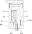
도 10은 본 발명의 다른 실시예에 따른 터빈용 브러시 실링장치를 나타낸 측면도이다. 본 실시예에서는 고정플레이트의 형상 및 브리스틀의 결합 위치를 제외한 기본적인 구성은 전술한 일실시예와 동일하므로 동일한 구성에 대한 구체적인 설명은 생략한다.10 is a side view showing a brush sealing apparatus for a turbine according to another embodiment of the present invention. In this embodiment, the basic configuration except for the shape of the fixing plate and the coupling position of the bristle is the same as that of the above-described embodiment, so that detailed description of the same configuration will be omitted.
도 10에서 보는 바와 같이, 상기 가이더부(232)는 상기 고정플레이트(231)의 하면 일측단에 돌설될 수 있다. 이때, 상기 브리스틀은 상기 가이더부(232)의 전방측에 대응되는 고정플레이트(231)의 하면부에 고정된다.As shown in FIG. 10, the
여기서, 상기 가이더부(232)의 하단부에는 상기 브리스틀은 전방측으로 가압하도록 돌설된 확장돌기부(233)가 구비됨이 바람직하다.Here, the lower end of the
이때, 상기 가이더부(232)는 후방측 커버부(220b)의 내측면에 지지되며, 상기 확장돌기부(233)는 상기 가이더부(232)의 전면측으로 돌출된 부분적인 원의 형상으로 구비될 수 있다.At this time, the
그리고, 상기 전방측 커버부(220a)에는 상기 확장돌기부(233)에 대응되는 부분의 하부를 따라 단턱부(223)가 구비될 수 있다. 이때, 상기 단턱부(223)은 상기 확장돌기부(233)에 의해 전방측으로 가압된 브리스틀을 후방측으로 재가압한다.The
이에 따라, 상기 브리스틀이 전방 및 후방으로 구배지게 휘어지며 상기 단턱부(223)의 상측에 걸림될 수 있다.Accordingly, the bristle can be bent in the forward and backward directions and can be hooked on the upper side of the
이와 함께, 상기 단턱부(223)에 의해 가압된 브리스틀은 상기 확장돌기부(233)를 상측으로 가압하여 상기 고정플레이트(231)를 장착부로 밀착시킬 수 있다.In addition, the bristle pressurized by the
이상 설명한 바와 같이, 본 발명은 상술한 각 실시예에 한정되는 것은 아니며, 본 발명의 청구항에서 청구한 범위를 벗어남 없이 본 발명이 속하는 기술 분야에서 통상의 지식을 가진 자에 의해 변형실시되는 것은 가능하며, 이러한 변형실시는 본 발명의 범위에 속한다.As described above, the present invention is not limited to the above-described embodiments, and variations and modifications may be made by those skilled in the art without departing from the scope of the present invention. And such modifications are within the scope of the present invention.
1: 로터부2,20: 케이싱
3: 다이아프램5: 래비린스형 실링장치
6: 투쓰7: 브러시부
8,9: 브리스틀 플레이트10: 회전체
21: 결합홈27: 파티션
27a: 블레이드100: 브러시 실링장치
110: 실링부111: 결합돌기
113: 래비린스 투쓰부114: 커버삽입홈부
115: 슬라이드홈부120,220a,220b: 커버부
121,122,221,222: 가압부123,124: 장착부
125: 슬라이드돌기부126,127: 관통공
128,129: 체결부삽입홈130,230: 브러시부
131,231: 고정플레이트132,232: 가이더부
133,233: 확장돌기부138,139: 브리스틀
140: 탄성부재223: 단턱부1:
3: Diaphragm 5: Labyrinth type sealing device
6: tooth 7: brush part
8,9: Bristol Plate 10: Rotor Whole
21: coupling groove 27: partition
27a: Blade 100: Brush sealing device
110: sealing part 111: engaging projection
113: Labyrinth touching portion 114: Cover insertion groove
115:
121, 122, 221, 222: pressing
125:
128, 129: fastening
131, 231: Fixing
133, 233:
140: elastic member 223:
Claims (5)
Translated fromKorean상기 실링부에 장착되되, 한쌍으로 구비되어 각각의 상부에 체결수단에 의해 상호 체결되는 장착부가 구비되며, 결합된 내부에 장착공간이 형성되고, 각각의 하부에 상호 대향되는 방향으로 돌출된 가압부가 형성되는 커버부; 및
상기 장착공간의 상부에 배치되는 고정플레이트와, 상단부가 상기 고정플레이트의 하면에 고정되되 하단부가 상기 회전체의 외주측으로 연장되어 상기 각 가압부 사이를 통과하며 가압되도록 배치되는 복수개의 브리스틀을 포함하되,
상기 고정플레이트의 하면에는 가이더부가 돌설되며, 상기 가이더부의 하단부에는 확장돌기부가 구비됨을 특징으로 하는 터빈용 브러시 실링장치.And a sealing portion mounted on an inner periphery of the casing to seal a flow of fluid flowing between a casing of the turbine and a rotating body rotated inside the casing, the brush sealing apparatus comprising:
A mounting portion mounted on the sealing portion and provided in a pair and fastened to each other by fastening means, a mounting space formed inside the fastening portion, and a pressing portion protruding in mutually opposite directions A cover portion formed; And
A plurality of bristles fixed to the lower surface of the stationary plate and having a lower end extending to an outer circumferential side of the rotatable body and passing through between the respective pressurizing portions, However,
Wherein a guider part is provided on a lower surface of the fixing plate, and an extension protrusion is provided on a lower end of the guider part.
상기 고정플레이트의 하면 중앙부에는 가이더부가 돌설되되, 상기 가이더부의 하단부에는 전방 및 후방으로 분할된 상기 브리스틀 사이의 공간을 확장하는 확장돌기부가 구비되며,
상기 확장돌기부의 하부는 상기 가압부에 의한 측방향 가압시 상기 고정플레이트가 상기 장착부의 하면에 밀착되도록 상광하협의 형상으로 구비됨을 특징으로 하는 터빈용 브러시 실링장치.The method according to claim 1,
Wherein a guider portion is provided at a central portion of a lower surface of the fixing plate and an extension protrusion is provided at a lower end portion of the guider portion to expand a space between the bristles divided forward and rearward,
Wherein the lower portion of the enlarged projection is formed in a shape of a vertical light-tight shape so that the fixing plate is in close contact with the lower surface of the mounting portion when the pressing portion is laterally pressed by the pressing portion.
상기 체결수단은 체결볼트 및 너트부재로 구비되고,
상기 각 장착부에는 상호 대향되는 부분을 따라 관통공이 형성되되, 상기 관통공의 테두리에는 상기 체결볼트의 헤드 및 상기 너트부재가 삽입되는 체결부삽입홈이 형성되며,
상기 장착부의 상단부에는 외측 테두리를 따라 슬라이드돌기부가 돌설되되, 상기 실링부에는 상기 장착부가 삽입되는 커버삽입홈부의 내측부를 따라 상기 슬라이드돌기부에 대응되는 슬라이드홈부가 형성됨을 특징으로 하는 터빈용 브러시 실링장치.The method according to claim 1,
Wherein the fastening means comprises a fastening bolt and a nut member,
Wherein each of the mounting portions is formed with a through hole along a portion thereof facing each other, wherein a head of the fastening bolt and a fastening portion insertion groove into which the nut member is inserted are formed at an edge of the fastening bolt,
Wherein a slide projection portion is formed along an outer edge of the upper end portion of the mounting portion and a slide groove portion corresponding to the slide projection portion is formed in the sealing portion along an inner side portion of a cover insertion groove portion into which the mounting portion is inserted. .
상기 브리스틀이 상기 가이더부의 하단부에 형성된 확장돌기부의 외면을 따라 밀착된 상태로 소성변형되도록 내측으로 가압되어 열처리되는 제2단계; 및
상기 고정플레이트가 한쌍으로 구비된 커버부의 내부에 배치되면 상기 각 커버부의 상부에 구비된 장착부가 체결수단에 의해 상호 체결되되, 상기 각 커버부의 내측부에 의해 상광하협의 형상으로 구비된 상기 확장돌기부의 하부가 가압되어 상기 고정플레이트가 상기 장착부에 밀착되고, 상기 각 커버부의 내측부 사이를 통과하도록 배치된 상기 브리스틀이 가압되는 제3단계를 포함하는 터빈용 브러시 실링장치의 제조방법.A first step in which the upper end of the bristle is fixed along the lower surface of the fixed plate provided with the downward guiding portion, and the fixed bristle is pressed and fixed by the electron beam welding so as to be in close contact with the guider portion;
A second step in which the bristle is pressurized inward to be plastic-deformed in a state of being closely adhered along an outer surface of an extended projection formed at a lower end of the guider part; And
Wherein when the fixing plate is disposed inside a pair of the cover portions, the mounting portions provided on the top portions of the cover portions are fastened to each other by the fastening means, and the extension projections And a third step in which the lower portion is pressed so that the fixing plate is brought into close contact with the mounting portion and the bristles arranged to pass between the inner side portions of the respective cover portions are pressed.
Priority Applications (1)
| Application Number | Priority Date | Filing Date | Title |
|---|---|---|---|
| KR1020150070629AKR101552919B1 (en) | 2015-05-20 | 2015-05-20 | sealing apparatus of turbine with brush and method for manufacturing thereof |
Applications Claiming Priority (1)
| Application Number | Priority Date | Filing Date | Title |
|---|---|---|---|
| KR1020150070629AKR101552919B1 (en) | 2015-05-20 | 2015-05-20 | sealing apparatus of turbine with brush and method for manufacturing thereof |
Publications (1)
| Publication Number | Publication Date |
|---|---|
| KR101552919B1true KR101552919B1 (en) | 2015-09-15 |
Family
ID=54248214
Family Applications (1)
| Application Number | Title | Priority Date | Filing Date |
|---|---|---|---|
| KR1020150070629AActiveKR101552919B1 (en) | 2015-05-20 | 2015-05-20 | sealing apparatus of turbine with brush and method for manufacturing thereof |
Country Status (1)
| Country | Link |
|---|---|
| KR (1) | KR101552919B1 (en) |
Cited By (1)
| Publication number | Priority date | Publication date | Assignee | Title |
|---|---|---|---|---|
| KR20180115936A (en) | 2017-04-14 | 2018-10-24 | 터보파워텍(주) | method for manufacturing brush seal |
Citations (4)
| Publication number | Priority date | Publication date | Assignee | Title |
|---|---|---|---|---|
| US5066024A (en) | 1988-01-29 | 1991-11-19 | Mtu Motoren- Und Turbinen-Union Munchen Gmbh | Brush-type seal |
| US20020130469A1 (en)* | 2001-03-13 | 2002-09-19 | Eagle Engineering Aerospace Co., Ltd | Brush seal device |
| JP2013155784A (en)* | 2012-01-27 | 2013-08-15 | Toshiba Corp | Shaft seal device |
| KR101449473B1 (en)* | 2014-05-29 | 2014-10-13 | 터보파워텍(주) | sealing apparatus of turbine with brush |
- 2015
- 2015-05-20KRKR1020150070629Apatent/KR101552919B1/enactiveActive
Patent Citations (4)
| Publication number | Priority date | Publication date | Assignee | Title |
|---|---|---|---|---|
| US5066024A (en) | 1988-01-29 | 1991-11-19 | Mtu Motoren- Und Turbinen-Union Munchen Gmbh | Brush-type seal |
| US20020130469A1 (en)* | 2001-03-13 | 2002-09-19 | Eagle Engineering Aerospace Co., Ltd | Brush seal device |
| JP2013155784A (en)* | 2012-01-27 | 2013-08-15 | Toshiba Corp | Shaft seal device |
| KR101449473B1 (en)* | 2014-05-29 | 2014-10-13 | 터보파워텍(주) | sealing apparatus of turbine with brush |
Cited By (1)
| Publication number | Priority date | Publication date | Assignee | Title |
|---|---|---|---|---|
| KR20180115936A (en) | 2017-04-14 | 2018-10-24 | 터보파워텍(주) | method for manufacturing brush seal |
Similar Documents
| Publication | Publication Date | Title |
|---|---|---|
| KR101442739B1 (en) | sealing apparatus with brush | |
| US9255486B2 (en) | Rotating brush seal | |
| KR101449473B1 (en) | sealing apparatus of turbine with brush | |
| RU2601324C2 (en) | Rotating brush seal | |
| JP5497063B2 (en) | Turbine wheel having a system for holding the blades axially | |
| JP2007146843A (en) | Variable clearance packing ring structure | |
| KR101524627B1 (en) | hybrid sealing apparatus of turbine | |
| JP6023272B2 (en) | Brush seal assembly | |
| KR101507500B1 (en) | Labyrinth seal and a reaction type steam turbine having the same | |
| JP2015110947A (en) | L brush seal for turbomachinery application | |
| KR101329622B1 (en) | Hybrid sealing apparatus for turbine | |
| EP3159491A1 (en) | Turbine's sealing assembly | |
| JP2015140926A (en) | Sealing device for providing seals in turbomachine | |
| KR101546385B1 (en) | sealing apparatus of turbine with brush | |
| KR102035657B1 (en) | Turbine apparatus | |
| CN106661943A (en) | Radial turbomachine | |
| RU2607195C2 (en) | Sealing assembly and rotary machine | |
| KR101552919B1 (en) | sealing apparatus of turbine with brush and method for manufacturing thereof | |
| KR20170083261A (en) | Hybrid sealing structure of a turbine | |
| JP6023273B2 (en) | Brush seal assembly | |
| KR101140295B1 (en) | Hybrid seal ring apparatus for turbine | |
| KR101771216B1 (en) | complex sealing apparatus for turbine | |
| KR101638480B1 (en) | brush sealing apparatus for turbine | |
| KR102256876B1 (en) | Axially faced seal system | |
| KR20010042489A (en) | Combined labyrinth and brush seals for rotary machines |
Legal Events
| Date | Code | Title | Description |
|---|---|---|---|
| PA0109 | Patent application | St.27 status event code:A-0-1-A10-A12-nap-PA0109 | |
| PA0201 | Request for examination | St.27 status event code:A-1-2-D10-D11-exm-PA0201 | |
| PA0302 | Request for accelerated examination | St.27 status event code:A-1-2-D10-D17-exm-PA0302 St.27 status event code:A-1-2-D10-D16-exm-PA0302 | |
| D13-X000 | Search requested | St.27 status event code:A-1-2-D10-D13-srh-X000 | |
| D14-X000 | Search report completed | St.27 status event code:A-1-2-D10-D14-srh-X000 | |
| PE0902 | Notice of grounds for rejection | St.27 status event code:A-1-2-D10-D21-exm-PE0902 | |
| E13-X000 | Pre-grant limitation requested | St.27 status event code:A-2-3-E10-E13-lim-X000 | |
| P11-X000 | Amendment of application requested | St.27 status event code:A-2-2-P10-P11-nap-X000 | |
| P13-X000 | Application amended | St.27 status event code:A-2-2-P10-P13-nap-X000 | |
| E701 | Decision to grant or registration of patent right | ||
| PE0701 | Decision of registration | St.27 status event code:A-1-2-D10-D22-exm-PE0701 | |
| GRNT | Written decision to grant | ||
| PR0701 | Registration of establishment | St.27 status event code:A-2-4-F10-F11-exm-PR0701 | |
| PR1002 | Payment of registration fee | St.27 status event code:A-2-2-U10-U11-oth-PR1002 Fee payment year number:1 | |
| PG1601 | Publication of registration | St.27 status event code:A-4-4-Q10-Q13-nap-PG1601 | |
| P22-X000 | Classification modified | St.27 status event code:A-4-4-P10-P22-nap-X000 | |
| PR1001 | Payment of annual fee | St.27 status event code:A-4-4-U10-U11-oth-PR1001 Fee payment year number:4 | |
| FPAY | Annual fee payment | Payment date:20190905 Year of fee payment:5 | |
| PR1001 | Payment of annual fee | St.27 status event code:A-4-4-U10-U11-oth-PR1001 Fee payment year number:5 | |
| PR1001 | Payment of annual fee | St.27 status event code:A-4-4-U10-U11-oth-PR1001 Fee payment year number:6 | |
| PR1001 | Payment of annual fee | St.27 status event code:A-4-4-U10-U11-oth-PR1001 Fee payment year number:7 | |
| PN2301 | Change of applicant | St.27 status event code:A-5-5-R10-R13-asn-PN2301 St.27 status event code:A-5-5-R10-R11-asn-PN2301 | |
| PR1001 | Payment of annual fee | St.27 status event code:A-4-4-U10-U11-oth-PR1001 Fee payment year number:8 | |
| PR1001 | Payment of annual fee | St.27 status event code:A-4-4-U10-U11-oth-PR1001 Fee payment year number:9 | |
| PR1001 | Payment of annual fee | St.27 status event code:A-4-4-U10-U11-oth-PR1001 Fee payment year number:10 | |
| PR1001 | Payment of annual fee | St.27 status event code:A-4-4-U10-U11-oth-PR1001 Fee payment year number:11 |