KR101552589B1 - Method for measuring overhead transmission line and calculating dig and actual tension thereof using ground light detection and ranging - Google Patents
Method for measuring overhead transmission line and calculating dig and actual tension thereof using ground light detection and rangingDownload PDFInfo
- Publication number
- KR101552589B1 KR101552589B1KR1020150083087AKR20150083087AKR101552589B1KR 101552589 B1KR101552589 B1KR 101552589B1KR 1020150083087 AKR1020150083087 AKR 1020150083087AKR 20150083087 AKR20150083087 AKR 20150083087AKR 101552589 B1KR101552589 B1KR 101552589B1
- Authority
- KR
- South Korea
- Prior art keywords
- steel tower
- wire
- calculating
- data
- mounting
- Prior art date
- Legal status (The legal status is an assumption and is not a legal conclusion. Google has not performed a legal analysis and makes no representation as to the accuracy of the status listed.)
- Active
Links
Images


Classifications
- G—PHYSICS
- G01—MEASURING; TESTING
- G01B—MEASURING LENGTH, THICKNESS OR SIMILAR LINEAR DIMENSIONS; MEASURING ANGLES; MEASURING AREAS; MEASURING IRREGULARITIES OF SURFACES OR CONTOURS
- G01B11/00—Measuring arrangements characterised by the use of optical techniques
- G—PHYSICS
- G01—MEASURING; TESTING
- G01B—MEASURING LENGTH, THICKNESS OR SIMILAR LINEAR DIMENSIONS; MEASURING ANGLES; MEASURING AREAS; MEASURING IRREGULARITIES OF SURFACES OR CONTOURS
- G01B11/00—Measuring arrangements characterised by the use of optical techniques
- G01B11/16—Measuring arrangements characterised by the use of optical techniques for measuring the deformation in a solid, e.g. optical strain gauge
- G—PHYSICS
- G01—MEASURING; TESTING
- G01L—MEASURING FORCE, STRESS, TORQUE, WORK, MECHANICAL POWER, MECHANICAL EFFICIENCY, OR FLUID PRESSURE
- G01L5/00—Apparatus for, or methods of, measuring force, work, mechanical power, or torque, specially adapted for specific purposes
- G01L5/04—Apparatus for, or methods of, measuring force, work, mechanical power, or torque, specially adapted for specific purposes for measuring tension in flexible members, e.g. ropes, cables, wires, threads, belts or bands
- G—PHYSICS
- G01—MEASURING; TESTING
- G01S—RADIO DIRECTION-FINDING; RADIO NAVIGATION; DETERMINING DISTANCE OR VELOCITY BY USE OF RADIO WAVES; LOCATING OR PRESENCE-DETECTING BY USE OF THE REFLECTION OR RERADIATION OF RADIO WAVES; ANALOGOUS ARRANGEMENTS USING OTHER WAVES
- G01S17/00—Systems using the reflection or reradiation of electromagnetic waves other than radio waves, e.g. lidar systems
- G01S17/88—Lidar systems specially adapted for specific applications
- G01S17/89—Lidar systems specially adapted for specific applications for mapping or imaging
- G—PHYSICS
- G01—MEASURING; TESTING
- G01S—RADIO DIRECTION-FINDING; RADIO NAVIGATION; DETERMINING DISTANCE OR VELOCITY BY USE OF RADIO WAVES; LOCATING OR PRESENCE-DETECTING BY USE OF THE REFLECTION OR RERADIATION OF RADIO WAVES; ANALOGOUS ARRANGEMENTS USING OTHER WAVES
- G01S7/00—Details of systems according to groups G01S13/00, G01S15/00, G01S17/00
- G01S7/48—Details of systems according to groups G01S13/00, G01S15/00, G01S17/00 of systems according to group G01S17/00
- G01S7/481—Constructional features, e.g. arrangements of optical elements
- G01S7/4817—Constructional features, e.g. arrangements of optical elements relating to scanning
- H—ELECTRICITY
- H02—GENERATION; CONVERSION OR DISTRIBUTION OF ELECTRIC POWER
- H02G—INSTALLATION OF ELECTRIC CABLES OR LINES, OR OF COMBINED OPTICAL AND ELECTRIC CABLES OR LINES
- H02G7/00—Overhead installations of electric lines or cables
- H02G7/20—Spatial arrangements or dispositions of lines or cables on poles, posts or towers
Landscapes
- Physics & Mathematics (AREA)
- General Physics & Mathematics (AREA)
- Engineering & Computer Science (AREA)
- Computer Networks & Wireless Communication (AREA)
- Radar, Positioning & Navigation (AREA)
- Remote Sensing (AREA)
- Electromagnetism (AREA)
- Electric Cable Installation (AREA)
Abstract
Translated fromKoreanDescription
Translated fromKorean본 발명은 지상라이다를 이용하여 가공철탑전선의 이도 및 실장에 필요한 데이터를 수집하고, 가공철탑전선로의 전선 이양에 요구되는 이도 및 실장 데이터를 효율적으로 확보할 수 있는 지상라이다를 이용한 가공철탑전선의 이도, 실장 관측 및 산출방법에 관한 것이다.The present invention relates to a method and apparatus for collecting data necessary for loading and unloading of a machining steel tower wire using a ground girder and for efficiently collecting the data required for transferring the wire to the machining steel tower wire, And more particularly, to a method and apparatus for monitoring a cable.
가공송전선로는 발전소에서 생산된 전기를 배전사업자에게 송전하는 선로로서 철탑 등의 지지물을 이용하여 공중에 설치되는 송전선로를 말한다.A machined transmission line is a transmission line for transmitting electricity generated by a power plant to a distribution company, and refers to a transmission line installed in the air using a support such as a pylon.
현재 345kV 이하 송전선로 건설에 사용되고 있는 공법은 전선을 표준화된 길이로 제작하여 전선을 직선 슬리브(전선 또는 부품을 덮는 절연용 튜브)로 연결, 압축 및 접속하면서 철탑 경간 사이에 연선하고, 설계상의 이도(중력에 의한 변형량, Dig 혹은 Sag)가 되도록 지지물 상에서 전선 늘어짐을 조정한 후 전선을 절단하고 인류 클램프(애자로 전선을 지지할 때 전선을 파지하기 위하여 사용하는 쇠붙이)를 압축하여 애자장치(전선을 지지물에 장치하는데 이용되는 절연용 장치)를 연결하도록 이루어진다. 이러한 기존 가선공법은 단도체 작업 시 유리할 수 있으나, 탑상 압축 작업이 많으므로 안전성이 저하되고 작업 일수가 증가하며, 직선 슬리브 사용으로 인해 신뢰성이 다소 떨어지는 단점이 있다.Currently, the method used for construction of transmission line under 345kV is to make the wires to standardized length, to connect the wires to the straight sleeves (insulating tubes covering the wires or parts), to compress and connect the wires, (The amount of deformation due to gravity, Dig or Sag), cut the wire, compress the metal clamp (metal used to hold the wire when supporting the insulator wire), and insulate the insulator To an insulating device used to mount the substrate to a support). Such conventional wire drawing method can be advantageous in single-conductor work, but it has a disadvantage that reliability is lowered due to the increase in number of working days and the use of straight sleeves because of a large amount of overhead compression work.
765kV 송전선 건설에 적용되고 있는 세미-프리팹(Semi-Prefab) 공법은, 전선을 내장철탑 간 길이로 분할 제작하여 전선의 일단부는 블록 통과형 압축인류 클램프를 지상에서 압축하여 링식 프로텍터(Ring type protector)를 압축한 클램프를 씌우고, 전선의 타단부는 쐐기식 클램프나 브레이드식 클램프(Braid type clamp)를 취부한 후, 클램프 간에 양쪽 애자련 길이만큼의 연결와이어를 사용하여 전력선을 연결하고, 상기 연결와이어 중간 지점이 내장철탑의 블록 중간에 위치하도록 연선하며, 연선 완료 후에 블록 통과형 압축 클램프는 내장애자련에 취부하고, 쐐기식 클램프 연결측은 설계상의 이도가 되도록 처짐 정도를 조정한 후 전선을 전단하여 탑상에서 클램프를 압축하고 애자련에 취부하는 공법이다. 상기 세미-프리팹 공법은 기존 가선공법에 비하여 절반 이상의 압축작업을 지상에서 수행하므로 품질을 향상시키고 무슬리브 공법으로 신뢰성은 확보할 수 있으나 연선클램프가 반드시 필요하고, 활차 통과 시 충격 하중이 발생할 수 있으며, 활차통과형 클램프, 프로텍터, 연결와이어 등 추가적인 자재가 필요하다는 단점이 있다.The Semi-Prefab method, which is applied to the construction of 765kV transmission line, divides the wire into the length between the built-in steel towers. One end of the wire compresses the block-type compression sleeve clamp on the ground to form a ring type protector ), And a wedge-type clamp or a braid type clamp is attached to the other end of the wire, and then the power lines are connected to each other using the connecting wires of both lengths between the clamps, After the twisting, the block-type compression clamp is attached to the inner barrel. The wedge-type clamp connection side adjusts the degree of deflection so that it is the design idle, The clamp is compressed on the top of the tower, and it is attached to the rotor. Since the semi-prefab method performs more than half of the compression work on the ground compared to the existing wire method, it improves the quality and secures the reliability by the non-sleeve method. However, a twisted clamp is necessary and an impact load There is a disadvantage that additional materials such as a pulley-passing clamp, a protector, and a connecting wire are required.
765kV 송전선 건설에 적용되고 있는 프리팹 공법은 긴선 작업 구간별로 제작된 전선 양단에 연선 시 지상에서 블록 통과형 압축인류 클램프를 압축하여 취부하고 연선한 후, 내장 철탑에서는 지상에서 압축한 압축인류 클램프를 애자련에 취부하고 이도의 미세 조정만 함으로써, 긴선 작업이 완료되는 공법이다. 상기 공법은 경간 내에 직선 슬리브 개소가 없을 뿐 아니라 탑상 압축 작업이 불필요하므로 가선 작업의 효율성, 품질확보 및 높은 안전성을 확보할 수 있다.In the prefab method, which is applied to the construction of 765kV transmission line, the block-type compression sleeve clamp is compressed and attached on both sides of the wire produced by the long working section, and the compressed steel sleeve It is a method of completing a long line work by attaching it to a pylon and fine-tuning it. Since the above method does not have a straight sleeve in the span and does not require an overhead compression operation, it is possible to ensure the efficiency of the wire cutting operation, the quality assurance, and the high safety.
그러나, 상기 프리팹 공법을 적용하기 위해서는 전선 지지점 간의 정확한 측량과 소도체별로 애자련의 길이 및 이도 등을 고려한 전선 실장, 블록 통과 등으로 인한 신장 등을 정밀하게 계산하여 전선 제작을 수행해야 하는 고도의 제작기술 및 시공 공법상 충분한 경험과 기술이 요구된다.However, in order to apply the pre-fab method, it is necessary to precisely measure the wire support points and to calculate the elongation due to the wire mounting, block passing, etc. considering the length and the angle of the insulator, Sufficient experience and skills are required in the manufacturing technology and construction method of
본 발명은 상기와 같은 문제점을 해소하고자 안출(案出)된 것으로서, 본 발명의 목적은 세미-프리팹 공법 또는 프리팹 공법 등에 적용할 수 있는 지상라이다를 이용하여 가공철탑전선의 이도 및 실장에 요구되는 데이터를 수집하거나, 가공철탑전선의 전선 이양에 필요한 이도 및 실장 데이터를 효율적으로 확보할 수 있는 지상라이다를 이용한 가공철탑전선의 이도, 실장 관측 및 산출방법을 제공하는데에 있다.SUMMARY OF THE INVENTION The present invention has been made to solve the above-mentioned problems, and an object of the present invention is to provide a method and apparatus for fabricating a steel wire tower by using a ground wire which can be applied to a semi-prefab method or a prefab method, The present invention also provides a method and apparatus for collecting data required for a steel tower wire, and a method and apparatus for monitoring the operation of a steel tower wire using a ground wire that can efficiently acquire data and mounting data necessary for transferring wire to the steel tower wire.
이러한 목적을 달성하기 위한 본 발명에 따른 지상라이다를 이용한 가공철탑전선의 이도, 실장 관측 및 산출방법은,In order to accomplish the above object, according to the present invention, there is provided a method,
(a) 지상라이다 측량 시스템으로 스캔데이터를 획득하는 단계(S11);(a) acquiring scan data with a terrestrial lidar surveying system (S11);
(b) 상기 단계(S11)에서 획득된 스캔데이터를 얼라인 작업으로 병합하는 단계(S12);(b) merging the scan data obtained in the step (S11) into an alignment operation (S12);
(c) 상기 단계(S12)에서 병합된 스캔데이터를 3차원 이미지의 점군데이터로 변환하는 단계(S13);(c) converting the merged scan data into the point cloud data of the three-dimensional image in the step S12 (S13);
(d) 상기 단계(S13)의 점군데이터를 기초로 철탑 모델과 가공철탑전선 모델을 생성하는 단계(S14); 및(d) generating (S14) a steel tower model and a working steel tower wire model based on the point cloud data in the step (S13); And
(e) 상기 단계(S14)의 철탑 모델과 가공철탑전선의 제1 이도를 산출하는 단계(S15);로 이루어지는 것을 특징으로 한다.(e) calculating (S15) the first idle of the steel tower model and the working steel tower wire in the step (S14).
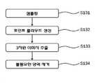
상기 (c)단계는, 스캔데이터에서 철탑 및 가공철탑전선을 샘플링(S131)하고, 상기 샘플링된 데이터의 깊이를 나타낸 이미지와 이를 색상으로 나타낸 이미지를 맵핑한 포인트 클라우드를 생성(S132)하며, 상기 포인트 클라우드에서 상기 철탑과 가공철탑전선을 모델링한 3차원 이미지가 추출(S133)되면서 불필요한 영역은 제거(S134)되는 것을 특징으로 한다.In step (c), the steel tower and the steel tower wire are sampled from the scan data (S131), and a point cloud in which an image representing the depth of the sampled data is mapped to an image representing the depth of the sampled data is generated (S132) In the point cloud, a three-dimensional image modeling the steel tower and the working steel tower wire is extracted (S133), and an unnecessary area is removed (S134).
상기 (e)단계는, 철탑 모델에서 획득한 철탑의 지반고와 가공철탑전선 모델에서 획득한 복수의 이도 측량 지점을 동일 평면 상에 배열하는 단계;Wherein the step (e) includes the steps of: arranging, on the same plane, a plurality of earing survey points obtained in the steel tower wire model obtained from the steel tower model obtained from the steel tower model;
상기 단계에서 이도 측량 지점의 고저차에 따라 철탑 모델에서 획득한 철탑과 이도 측량 지점을 단일 곡선 형태로 연결하는 제1 피라미터를 부가하는 단계; 및Adding a first pyrameter connecting the pylon and the earing point obtained in the pylon model according to the elevation difference of the earing survey point in a single curve form; And
상기 단계의 철탑과 제1 피라미터를 토대로 현재의 온도에서의 제1 이도를 계산하는 단계;로 이루어지는 것을 특징으로 한다.And calculating a first angle at a current temperature based on the steel tower and the first pyrameter in the step.
한편, 상기 (e)단계 이후에, 제1 이도를 바탕으로 최악조건의 온도에서 변화이도를 구하여 변경 피라미터를 계산하고, 상기 변경 피라미터를 토대로 최악조건에서의 실장을 산출하는(S16);를 더 포함하는 것을 특징으로 한다.On the other hand, after the step (e), the variation diagram is calculated from the temperature of the worst condition on the basis of the first diagram, and the variation in the worst condition is calculated based on the variation pyrameter (S16). And further comprising:
또한, 상기 (e)단계 이후에, 제1 이도, 전선 지지점의 고저차 및 경간을 이용하여 상기 가공철탑전선의 최악조건 실장을 산출하는 단계;를 더 포함하는 것을 특징으로 한다.Further, the method may further include calculating a worst-case condition mount of the machined steel tower wire using the first angle, the elevation difference and the span of the wire support point after the step (e).
아울러, 상기 지상라이다 측량시스템은 300nm 내지 535nm 중심파장의 레이저를 발진하고, 접속된 콘트롤러에 의해 작동이 제어되며, 광원에 연결되고 상기 광원으로부터 조사되는 레이저의 초점을 조절하는 초점 조절 모듈(110)과 상기 초점 조절 모듈(110)과 연결되며, 상기 광원을 고정하는 마운트(120)와 상기 광원과 측정거리와의 정렬을 가능케하는 정렬 모듈(130)로 구성되는 것을 특징으로 한다.In addition, the terrestrial lidar measuring system includes a
본 발명에 따른 지상라이다를 이용한 가공철탑전선의 이도, 실장 관측 및 산출방법은 측량자가 고공의 철탑에 올라가지 않고도 지상에서 라이다로 수집한 스캔데이터를 이용하여 가공철탑전선의 이도 및 실장을 정밀하게 측정하고, 분석 및 데이터의 저장을 용이하게 할 수 있다. 따라서, 작업자의 오류에 의한 신뢰성 저하를 방지하면서 작업 신뢰성, 효율성 및 작업자의 안전성을 향상시킬 수 있으며, 또한, 지상라이다의 스캔데이터를 분석하여 가공철탑전선을 지지하는 철탑 등의 지지물 변위를 측정할 수 있으므로, 이도 및 실장 산출 시, 철탑 변위를 고려한 정확한 이도 및 실장을 계산할 수 있다. 더불어, 지상라이다를 이용함으로써, 가공철탑전선의 전선 이양에 필요한 이도 및 실장 데이터를 신뢰성 있게 제공하며, 세미-프리팹 공법 또는 프리팹 공법 등에 필요한 해당 지형 데이터, 철탑 데이터 및 가공철탑전선의 이도 및 실장 데이터를 제공할 수 있는 효과가 있다.According to the present invention, by using the scan data collected from the ground by the surveyor without having to go up to the high-rise steel tower, the guide and the mounting of the processed steel tower cable can be precisely And facilitate the analysis and storage of data. Therefore, it is possible to improve the reliability of operation, efficiency and safety of the operator while preventing the reliability from being lowered by the operator's error, and also to analyze the scan data of the ground lidar to measure the support displacement of the steel tower supporting the working steel tower wire Therefore, it is possible to calculate the accurate diagram and the mounting considering the pylon displacement when calculating the diagram and the mounting. In addition, by using the ground lidar, it is possible to reliably provide the islands and the mounting data necessary for transferring the wires of the machined steel tower wires, and to provide appropriate terrain data, such as the semi-prefab method or prefab method, And the mounting data can be provided.
도 1은 본 발명의 바람직한 일 실시예에 따른 지상라이다를 이용한 가공철탑 전선의 이도, 실장 관측 및 산출방법(이하, '이도 실장 산출방법' 이라 한다)을 나타낸 순서도이다.
도 2는 본 발명의 바람직한 일 실시예에 따른 지상라이다를 이용한 가공철탑전선의 이도, 실장 관측 및 산출방법에서의 이도 실장 산출 방법(이하 '이도 실장 산출방법' 이라 한다)의 스캔데이터 변환 과정을 나타낸 흐름도이다.
도 3a 및 도 3b는 본 발명의 바람직한 일 실시예에 따른 지상라이다를 이용한 가공철탑전선의 이도, 실장 관측 및 산출방법에서의 이도 실장 산출 방법의 점군데이터를 도시한 예시도이다.
도 4는 본 발명의 바람직한 일 실시예에 따른 지상라이다를 이용한 가공철탑전선의 이도, 실장 관측 및 산출방법에서 이도 실장 산출방법을 실행하는 시스템을 나타낸 블록도이다.
도 5a 및 도 5b는 본 발명의 바람직한 일 실시예에 따른 지상라이다를 이용한 가공철탑전선의 이도, 실장 관측 및 산출방법에서 이도 실장 산출방법 중 이도 산출 과정을 설명하기 위한 예시도이다.
도 6은 본 발명의 바람직한 일 실시예에 따른 지상라이다를 이용한 가공철탑전선의 이도, 실장 관측 및 산출방법에서 전선 지지점의 높이가 동일한 경우의 이도 산출 과정을 나타낸 모식도이다.
도 7은 본 발명의 바람직한 일 실시예에 따른 지상라이다를 이용한 가공철탑전선의 이도, 실장 관측 및 산출방법에서 전선 지지점 간의 고저차를 고려한 이도 산출 과정을 나타낸 모식도이다.
도 8은 본 발명의 바람직한 일 실시예에 따른 지상라이다를 이용한 가공철탑전선의 이도, 실장 관측 및 산출방법에 이용되는 지상라이더를 도시한 평면도이다.FIG. 1 is a flow chart showing a method of measuring and measuring a machining steel tower wire using a ground ladder according to a preferred embodiment of the present invention (hereinafter referred to as a "method of calculating a guide mounting surface").
FIG. 2 is a block diagram illustrating a scan data conversion process of a method of calculating a road surface mounting method (hereinafter, referred to as a "road surface mounting method") in a road surface, a mounting surface observation method, and a calculation method of a working steel tower wire using a ground lid according to a preferred embodiment of the present invention Fig.
FIG. 3A and FIG. 3B are diagrams illustrating point cloud data of a method of calculating a road surface mounting method in a method of mounting, mounting, and calculating a steel wire tower using a ground lid according to a preferred embodiment of the present invention.
FIG. 4 is a block diagram showing a system for executing the method of calculating the road surface mounting method in the track, mounting view, and calculation method of a working steel tower wire using a ground lid according to a preferred embodiment of the present invention.
FIGS. 5A and 5B are diagrams for explaining a calculation process of a method of calculating a road surface mounting method in the track, mounting, and calculation method of a wire towed wire using a ground lid according to a preferred embodiment of the present invention.
FIG. 6 is a schematic view illustrating a process of calculating a gypsum line when the height of a wire support point is the same in a gypsum, a mounting observation, and a calculation method of a working steel tower wire using a ground lid according to a preferred embodiment of the present invention.
FIG. 7 is a schematic diagram illustrating a process of calculating a gypsum length in consideration of a difference in height between wire support points in a gypsum, a mounting observation, and a calculation method of a working steel tower wire using a ground lid according to a preferred embodiment of the present invention.
FIG. 8 is a plan view showing a ground rider used in a method of measuring a ground wire, a mounting view, and a calculation method of a wire towed wire using a ground wire according to a preferred embodiment of the present invention.
본 발명은 일면에 있어서,In one aspect of the present invention,
가공철탑전선의 이도, 실장 관측 및 산출방법은,The machining of the steel tower wire, the mounting observation and the calculation method,
(a) 지상라이다 측량 시스템으로 스캔데이터를 획득하는 단계(S11);(a) acquiring scan data with a terrestrial lidar surveying system (S11);
(b) 상기 단계(S11)에서 획득된 스캔데이터를 얼라인 작업으로 병합하는 단계(S12);(b) merging the scan data obtained in the step (S11) into an alignment operation (S12);
(c) 상기 단계(S12)에서 병합된 스캔데이터를 3차원 이미지의 점군데이터로 변환하는 단계(S13);(c) converting the merged scan data into the point cloud data of the three-dimensional image in the step S12 (S13);
(d) 상기 단계(S13)의 점군데이터를 기초로 철탑 모델과 가공철탑전선 모델을 생성하는 단계(S14); 및(d) generating (S14) a steel tower model and a working steel tower wire model based on the point cloud data in the step (S13); And
(e) 상기 단계(S14)의 철탑 모델과 가공철탑전선의 제1 이도를 산출하는 단계(S15);로 이루어지는 것을 특징으로 하는 지상라이다를 이용한 가공철탑전선의 이도, 실장 관측 및 산출방법을 제공한다.and (e) calculating a first idle of the steel tower model and the machining steel tower wire in the step (S14). The method of claim 1, wherein the step (S15) to provide.
이하, 본 발명의 바람직한 실시예에 대하여 첨부된 도면을 참조하여 상세하게 설명한다.Hereinafter, preferred embodiments of the present invention will be described in detail with reference to the accompanying drawings.
이에 앞서, 본 명세서 및 특허청구범위에 사용된 단어는 통상적이거나 사전적인 의미로 한정 해석하지 아니하며, 발명자는 그 자신의 발명을 가장 최선의 방법으로 설명하기 위해 용어의 개념을 적절하게 정의할 수 있다는 원칙에 입각하여 본 발명의 기술적 사상에 부합하는 의미와 개념으로 해석되어야만 한다.Prior to this, words used in this specification and claims are not to be construed in a conventional or dictionary sense, and the inventor can appropriately define the concept of a term to describe its own invention in the best way And should be construed in accordance with the principles and meanings and concepts consistent with the technical idea of the present invention.
송전 철탑의 변위 측정 또는 이도 및 실장 분석은 크게 외업 작업과 내업 작업으로 나누어 행해질 수 있는데, 작업자의 위험 발생도는 외업 작업 시 주로 발생한다. 다시 말하면, 철탑 등의 지지물에 매달린 가공철탑전선의 이도 및 실장을 위해서는 작업자(측정자)가 반드시 상기 철탑 상부로 올라가야 하는데, 이때 철탑 상태를 측정할 때 발생되는 위험이 잠재적으로 내재되어 있다.The measurement of the displacement of the transmission tower or the analysis of the islands and the installation can be divided into external work and internal work. In other words, a worker (measurer) must ascend to the upper part of the steel tower in order to guide and mount the steel wire tower suspended from a support such as a steel tower, and there is a risk inherent in measuring the state of the steel tower.
한편, 철탑의 선로에는 66kV 내지 765kV 등의 특고압이 흐르고 있으므로 작업자의 위험도 및 실측 오차로 인하여, 가공철탑 상태의 정확한 측정이 어려울 수 있다. 따라서, 본 발명에서는 건물이나 댐 교량을 스캔 모델링하는데 주로 사용되었던 지상라이다를 본 발명에 적용시켜 철탑과 가공철탑전선을 정확하게 측정하고, 이도 및 실장을 효율적으로 산출함으로써, 전술한 문제점 등을 해소하고자 한다.On the other hand, due to the extraordinary high voltage such as 66 kV to 765 kV flowing in the line of the steel tower, accurate measurement of the state of the steel tower can be difficult due to the risk and the measurement error of the operator. Therefore, in the present invention, the above-described problems can be solved by accurately measuring the steel towers and the machined steel tower wires by applying the ground lidar, which has been mainly used for modeling a building or dam bridge, to the present invention, I want to.
도 1은 본 발명의 일 실시예에 따른 지상라이다를 이용한 가공철탑전선의 이도, 실장 관측 및 산출방법(이하 '이도 실장 산출방법' 이라 한다)을 나타낸 순서도이다.FIG. 1 is a flowchart showing a method of measuring and measuring an operation, a mounting, and a calculation method (hereinafter, referred to as a "method of calculating an installation method") of a working steel tower wire using a ground lid according to an embodiment of the present invention.
도 1에 나타낸 순서도를 참조하면, 먼저 이도 실장 산출을 위한 지상라이다를 이용하여 철탑과 가공철탑전선에 대한 스캔데이터 획득 단계를 수행할 수 있다(S11).Referring to the flowchart shown in FIG. 1, first, a scan data acquisition step for a steel tower and a working steel tower wire can be performed by using a ground wire for calculation of a guide wire mounting (S11).
그리고, 상기 획득된 스캔데이터를 얼라인 작업으로 병합하는 작업을 실시한다(S12).Then, the acquired scan data is merged into the alignment operation (S12).
상기 병합된 스캔데이터는 3차원 이미지의 점군데이터로 변환하는 단계를 수행한다(S13).The merged scan data is converted into point cloud data of a three-dimensional image (S13).
다음, 상기 점군데이터에서 철탑을 추출한 철탑 모델과 가공철탑전선을 추출한 가공철탑전선 모델을 생성할 수 있다(S14).Next, a steel tower model in which a steel tower is extracted from the point cloud data and a processed steel tower wire model in which a processed steel tower wire is extracted can be generated (S14).
그 다음으로, 상기 철탑 모델과 가공철탑전선을 모델로 구성한 3차원 가공철탑전선 영상데이터에서 전선의 이도를 산출하는 단계를 수행한다(S15).Next, in step S15, a step of calculating the roadway of the wire is performed on the three-dimensional processed steel tower wire image data constituted by the steel tower model and the machining steel tower wire as a model.
추가로, 앞서 설명한 전선의 이도와 철탑 모델에서 획득한 경간 및 철탑 고저차를 적용하여 전선의 실장(실제 길이)를 산출하는 단계를 수행할 수 있다(S16).In addition, the step (S16) of calculating the mounting (actual length) of the electric wire by applying the gyro of the electric wire, the span obtained in the electric tower model and the elevation difference of the electric tower may be performed.
전술한 이도 실장 산출방법은 PC에 탑재된 프로세서가 메모리 시스템에 저장된 프로그램을 수행하는 것으로 구현될 수 있다.The above-described method of calculating the road surface mounting can be implemented by a processor mounted on the PC executing a program stored in the memory system.
예를 들어, 특정 철탑 사이의 가공철탑전선에 대한 이도 및 실장 산출방법은 스캔 단계, 비교 및 분석 단계 그리고 결과 산출 단계를 포함할 수 있는데, 스캔 단계를 수행하기 전에 사전 준비로서 스캔 위치를 선정할 수 있다. 상기 스캔 단계에서는 지상라이다를 이용하여 측정한 철탑과 가공철탑전선에 대한 스캔 작업을 수행한다. 한편, 비교 및 분석 단계에서는 복수의 스캔데이터를 얼라인하여 병합한다. 그리고, 이미지 및 수치 확인 등의 분석 작업을 수행 후에, 결과 산출 단계에서는 분석 작업으로 얻은 데이터를 토대로 가공철탑전선의 이도 및 실장을 계산하고, 계산 결과를 미리 설정된 보고서 포맷에 따라 결과 보고서를 생성하고 저장하거나 출력할 수 있다.For example, the method of calculating the landing and mounting for a steel tower wire between specific steel towers may include a scanning step, a comparing and analyzing step, and a result calculating step. . In the scanning step, scanning is performed on the steel towers and the steel tow wires measured using the ground lidar. In the comparison and analysis step, a plurality of scan data are aligned and merged. After analyzing the images and numerical values, the result calculation step calculates the diagrams and implementations of the wire towers on the basis of the data obtained by the analysis and generates the calculation results according to the preset report format Can be stored or output.
하기에서는 전술한 이도 및 실장 산출방법을 좀 더 구체적으로 설명한다.In the following, the above-described diagram and method of calculating the mounting will be described in more detail.
먼저, 스캔 단계 전에 철탑이 위치한 장소나 주변 환경에 따라 어떤 위치에서 철탑과 가공철탑전선을 다중 스캔할지 결정한다.First, determine where to scan the steel tower and the steel tower wires at multiple locations, depending on the location of the tower and the surrounding environment before the scanning step.
스캔 단계에서는 3차원 스캔 작업을 수행하는 단계로서, 지상라이다의 레이저를 이용하여 원거리의 피사체(철탑, 가공철탑전선 등)의 형상을 입력하여 3차원 이미지로 저장한다.In the scanning step, a three-dimensional scanning operation is performed, and a shape of a remote object (a steel tower, a steel tower wire, etc.) is input using a laser of a terrestrial laser and stored as a three-dimensional image.
상기 지상라이다는 예컨대, 스캔 거리가 약 600m 이내이고, 원거리의 피사체에 대한 점군데이터(Point clould data)를 산출할 수 있다. 또한, 스캔 작업에서는 피사체 주변에서 표현이 되지 않는 피사체 부분이 없도록 다각도에서 피사체를 스캔한다. 스캔 시에는 피사체의 표현 부분을 어디까지 할지를 결정하여 스캔하는게 바람직하다. 한편, 피사체의 표현 부분은 스캔데이터의 다수의 점에 해당한다.For example, the ground line can calculate point clould data for a distance object within a scan distance of about 600 m. In addition, in a scanning operation, the subject is scanned in multiple angles so that there is no part of the subject that is not represented in the vicinity of the subject. In scanning, it is preferable to determine the position of the expression part of the subject and scan it. On the other hand, the expression part of the subject corresponds to a plurality of points of the scan data.
비교 및 분석 단계에서는 얼라인(align) 작업으로 다각도에서 획득한 스캔데이터를 병합하여 단일 파일로 생성할 수 있다. 또한, 원하는 피사체의 형상을 점군데이터로 만들 수 있다. 상기 점군데이터는 철탑 모델, 가공철탑전선 모델 또는 이들의 조합 모델로 생성될 수 있다.In the comparing and analyzing step, the scan data obtained from the multiple view can be merged into a single file by the align operation. In addition, the shape of a desired subject can be made into point cloud data. The point cloud data may be generated as a steel tower model, a machined steel tower wire model, or a combination model thereof.
결과 산출 단계에서는 철탑 모델과 가공철탑전선 모델에 의하여 생성되는 실제 형상과 동일한 구조의 3차원 이미지에서 가공철탑전선의 이도를 산출하고 실장을 계산한 후, 산출된 이도 및 실장에 대한 결과 데이터를 작업자나 관리자가 확인할 수 있는 데이터로 변환하여 결과 리포트로 저장, 출력 혹은 전송시킬 수 있다.In the result calculation step, the image of the machined steel tower wire is calculated from the three-dimensional image having the same structure as the actual shape generated by the steel tower model and the machined steel tower wire model, It can be converted into data that can be confirmed by the user or the administrator and stored, output or transmitted as a result report.
도 2는 이도 실장 산출방법에서의 점군데이터 변환 과정을 나타낸 흐름도이다.FIG. 2 is a flowchart showing a process of converting point cloud data in the road surface mounting calculation method.
상기 점군데이터 변환 과정을 도 2를 참조하여 설명하면 다음과 같다.The point-group data conversion process will be described with reference to FIG.
먼저, 프로세서에 지상라이다로부터 다양한 측량 지점 혹은 스캔 지점에서의 스캔데이터를 수신하여 샘플링할 수 있다(S131). 다시 말하면, 상기 프로세서는 스캔데이터에서 철탑 등의 가공철탑전선 지지물과 가공철탑전선을 중심으로 스캔데이터를 샘플링하는 것이다.First, the processor may receive and sample scan data at various survey points or scan points from the terrestrial ladder (S131). In other words, the processor samples the scan data around the machined steel tower wire support such as a steel tower and the machined steel tower wire from the scan data.
다음, 샘플링된 데이터를 깊이를 나타내는 이미지와 색상 이미지로 맵핑한 포인트 클라우드를 생성한다(S132).Next, a point cloud in which the sampled data is mapped to an image representing a depth and a color image is generated (S132).
그리고, 상기 포인트 클라우드에서 철탑과 가공철탑전선을 모델링한 3차원 이미지를 추출할 수 있다(S133). 추출된 철탑의 3차원 이미지는 철탑 모델로 저장되고, 가공철탑전선의 3차원 이미지를 가공철탑전선 모델로 저장할 수 있다. 이 경우에는, 3차원 이미지가 각각의 레이어(층)로 저장될 수 있고, 원하는 복수 레이어를 중첩되게 표시할 수 있다.Then, a three-dimensional image modeling the steel tower and the working steel tower wires in the point cloud can be extracted (S133). The three-dimensional image of the extracted steel tower is stored as a steel tower model, and a three-dimensional image of the processed steel tower wire can be stored as a machined steel tower wire model. In this case, the three-dimensional image can be stored in each layer (layer), and a plurality of desired layers can be displayed superimposed.
한편, 구현에 따라서 3차원 이미지를 추출할 때, 미리 기록된 위치 정보에 따라 스캔데이터와 동시에 촬영된 고해상도 카메라의 영상데이터를 토대로 추출된 3차원 이미지에서의 불필요한 영역을 제거할 수 있는 단계를 수행할 수 있다(S134).Meanwhile, when extracting a three-dimensional image according to the implementation, a step of removing an unnecessary region in the extracted three-dimensional image based on the image data of the high-resolution camera captured simultaneously with the scan data according to the previously recorded position information (S134).
전술된 3차원 이미지는 점군데이터로 표시될 수 있는데, 상기 점군데이터를 예시하면 도 3a 및 도 3b와 같다.The above-mentioned three-dimensional image can be represented by point cloud data. The point cloud data is shown in FIGS. 3A and 3B.
도 3a 및 도 3b에 도시한 바와 같이, 점군데이터를 이용하면 철탑의 높이, 지반고, 지반고저차 및 경간을 즉각적으로 계산할 수 있는 용이성이 있다. 즉, 3차원 이미지의 점군데이터로 실제와 동일한 철탑과 가공철탑전선을 포함하는 가공철탑전선로를 생성하고, 가공철탑전선로 구조에서 철탑의 지지점 고저차, 경간 및 변위를 실시간으로 계산하여 산출할 수 있다.As shown in FIGS. 3A and 3B, when the point cloud data is used, the height, the ground height, the ground level difference, and the span of the steel tower can be calculated immediately. In other words, it is possible to generate a machined steel tower electric line including the same steel tower and machined steel tower wire as the actual point group data of the three-dimensional image, and calculate the elevation difference, span and displacement of the steel tower at the steel tower electrical wire structure in real time .
또한, 측정 위치 또는 측정 시간과 함께 측정 위치에서의 온도를 스캔데이터와 동시에 저장하면, 스캔을 수행할 시의 온도를 근거로 특정 온도에서의 현재 이도를 계산할 수 있다. 상기와 같은 방식으로 이도를 계산하면, 피라미터를 변경하여 최악의 조건을 가정하여 예상적 피라미터를 갖는 이도를 계산할 수도 있다. 참고로, 상기 최악 조건 이도는 실제로 가선이나 이양 작업 시 실장을 계산하기 위하여 필수적으로 요구되는 데이터이다.In addition, when the temperature at the measurement position together with the measurement position or measurement time is stored simultaneously with the scan data, the current position at a specific temperature can be calculated based on the temperature at the time of performing the scan. If the isotope is calculated in the above-described manner, it is possible to calculate the isotope having the expected pyramid by assuming the worst condition by changing the pyrameter. For reference, the worst condition idol is data that is indispensably required in order to actually calculate the mounting in a wire or transfer work.
한편, 상기 점군데이터를 이용하면 철탑의 평면 데이터를 추출하거나, 기초 부분 또는 앵글 부분의 높이를 측정할 수 있으며, 측면 기둥부의 높이나 경사각을 측정할 수도 있다. 따라서, 2차원 평면 상에서 철탑의 수직 중심축이 어떤 방향에서 얼마만큼 기울어졌는지에 대한 변위를 측정할 수 있는 것이다.On the other hand, if the point cloud data is used, flat data of the steel tower can be extracted, the height of the base portion or the angle portion can be measured, and the height or the tilt angle of the side column portion can be measured. Therefore, it is possible to measure the displacement of the vertical center axis of the steel tower on the two-dimensional plane with respect to how much the vertical center axis is inclined in any direction.
도 4는 도 1에 나타낸 이도 실장 산출방법을 실행하는 시스템을 나타낸 블록도이다.FIG. 4 is a block diagram showing a system for executing the method of FIG. 1; FIG.
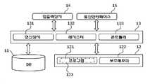
본 발명의 실시예에 따른 이도 실장 산출방법을 실행하는 시스템(이하 '이도 실장 산출시스템' 이라 한다)은 데이터베이스(DB), 메모리시스템, 프로세서, 입출력장치 및 통신 인터페이스를 포함하여 구현될 수 있다.A system (hereinafter, referred to as an " image mounting calculation system ") that implements an image mounting method according to an embodiment of the present invention may be implemented including a database (DB), a memory system, a processor, an input / output device, and a communication interface.
상기 데이터베이스는 지상라이다에 의해 수집된 철탑 등의 지지물과 상기 지지물에 매달린 가공철탑전선의 스캔데이터 등을 저장한다. 한편, 상기 데이터베이스는 시간별 혹은 일자별로 측정 및 분석된 스캔데이터, 상기 스캔데이터를 변환하여 얻어진 3차원 이미지의 점군데이터 등을 저장할 수 있다.The database stores a support such as a steel tower collected by a ground girder and scan data of a steel tower wire suspended from the support. Meanwhile, the database may store scan data measured and analyzed by time or by day, point cloud data of a three-dimensional image obtained by converting the scan data, and the like.
상기 메모리시스템은 수집되어 분석된 프로그램 등을 저장한다. 지상라이다를 이용한 가공철탑전선의 이도, 실장 관측 및 산출방법을 구현한 프로그램은 프로세서에 의해 실행될 때, 메인메모리에 로딩될 수 있다. 여기서, 상기 프로그램은 도 1을 참조하여 설명한 이도 실장 산출방법 또는 도 2을 참조하여 설명한 스캔데이터 변환을 위한 일련의 절차를 표현하도록 구현될 수 있다.The memory system stores collected and analyzed programs and the like. A program that implements the guidance, mounting observations and calculation method of a machining steel tower wire using ground lidar can be loaded into main memory when executed by a processor. Here, the program may be implemented to represent the image pickup mounting calculation method described with reference to FIG. 1 or a series of procedures for scan data conversion described with reference to FIG.
또한, 상기 메모리시스템은 RAM 및 ROM과 같은 저장 매체 또는 하드디스크, CD, DVD, 블루레이 및 플래시 메모리 등의 저장 매체 형태인 보조메모리를 포함하여 구성될 수 있다.In addition, the memory system may comprise a storage medium such as RAM and ROM or an auxiliary memory in the form of a storage medium such as a hard disk, CD, DVD, Blu-ray and flash memory.
상기 프로세서는 시스템의 중앙처리장치로서, 일반적인 PC 등에 사용되는 CPU를 사용할 수 있다. 상기 프로세서는 계산을 수행하는 연산장치, 데이터 및 명령어의 일시적인 저장을 위한 레지스터 및 시스템의 각 구성요소를 제어하는 콘트롤러를 포함하여 구성된다.The processor is a central processing unit of the system, and a CPU used in a general PC or the like can be used. The processor comprises an arithmetic unit for performing calculations, a register for temporary storage of data and instructions, and a controller for controlling each component of the system.
상기 입출력 장치는 사용자 인터페이스를 포함할 수 있다. 입출력 장치는 사용자의 명령어를 수행하거나, 수행한 명령에 대한 응답을 텍스트 또는 그래픽으로 표현하여 구동될 수 있는데, 이러한 입출력 장치는 입력 포트, 출력 포트, 키보드, 마우스 및 터치 패널 또는 이들의 조합으로 구현될 수 있다.The input / output device may include a user interface. The input / output device may be implemented by executing a command of a user or expressing a response to an executed command in a text or graphic form. The input / output device may be implemented by an input port, an output port, a keyboard, a mouse, a touch panel, .
상기 통신 인터페이스는 유무선 네트워크를 통하여 작업자의 단말기나 관리자의 서버에 접근하기 위한 수단 또는 구성부를 지칭한다. 통신 인터페이스는 근거리 무선통신, 차량간 통신, 이동통신망 및 위성망 등의 통신 방식 중 적어도 어느 하나를 지원하는 통신 모듈로 이루어질 수 있다.The communication interface refers to a means or a component for accessing a terminal of an operator or a server of an administrator through a wired or wireless network. The communication interface may be a communication module supporting at least one of a short-range wireless communication, a vehicle-to-vehicle communication, a mobile communication network, and a communication system such as a satellite network.
한편, 본 발명의 일 실시예에 따른 가공철탑전선의 이도 및 실장 등의 데이터를 수집하기 위해 차량을 이용할 경우, 좁은 도로 또는 산악 지형 등과 같은 차량 진입이 곤란한 경우가 발생할 수 있는데, 이때에는 소위 '드론'과 같은 소형 무인 항공기를 이용하여 항공라이다 방식의 장치로 구현할 수도 있다.On the other hand, when the vehicle is used for collecting data such as the roadway and the mounting of the processed steel tower wire according to the embodiment of the present invention, it may be difficult to enter the vehicle such as a narrow road or a mountainous terrain. A small unmanned airplane such as a drones may be used as an air ladder system.
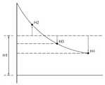
도 5a 및 5b는 도 1에 나타낸 방법 중 하나인 이도 산출 과정을 설명하기 위한 예시도이다.FIGS. 5A and 5B are diagrams for explaining a process of calculating the number of teeth, which is one of the methods shown in FIG. 1. FIG.
본 발명의 실시예의 이도 실장 산출시스템은 점군데이터에서 철탑 중심을 측량하여 상기 철탑의 지반고를 계산한다. 철탑의 지반고는 상기 철탑의 측정 위치와 철탑의 사거리 및 수직각을 이용하여 피타고라스 정리의 공식에 적용되어 계산할 수 있다.The isoelectric point calculation system of the embodiment of the present invention calculates the ground height of the steel tower by measuring the center of the tower in the point cloud data. The elevation of the pylon can be calculated by applying it to the Pythagorean theorem using the measured position of the pylon and the slope and vertical angle of the pylon.
철탑의 지반고가 계산되면, 도 5a에 도시된 바와 같이, 각각의 이도 측량 지점(H2, H3, H4)과 철탑의 지반고(H1)를 동일 평면상에 표시한다.When the elevation of the steel tower is calculated, as shown in FIG. 5A, each of the excitation points H2, H3, and H4 and the elevation H1 of the elevation tower are displayed on the same plane.
그 다음, 도 5b에 도시한 바와 같이 철탑과 각각의 이도 측량 지점의 고저차(H2, H3, H4)에 맞는 피라미터를 자연스런 곡선 형태로 부가하여 그려준다. 선 형태의 피라미터가 그려지면, 철탑 사이의 경간을 계산할 때, 그은 직선과 평행한 접선을 이용하여 상기 직선과 가장 멀리 위치한 피라미터 곡선상의 위치를 추출하여 이도를 계산할 수 있다. 계산된 이도는 특정 시간과 그 시간의 온도 조건에서의 현재 이도가 된다.Then, as shown in FIG. 5B, a pyrameter corresponding to the elevation difference H2, H3, and H4 of the iron tower and the respective surveying points is added in a natural curve form. When a line-shaped pyrameter is drawn, when calculating the span between the steel towers, the tongue can be calculated by extracting the position on the pyrameter curve located farthest from the straight line by using a tangent line parallel to the straight line. The computed tooth is the current tooth at a specific time and temperature condition for that time.
현재 이도가 계산되어 산출되면, 이를 바탕으로 최악 조건 피라미터를 예측하기 위해 이도의 조건 변경을 수행할 수 있다. 즉, 특정 온도에서의 현재 이도를 이용하여 최악 조건 온도(예를 들어 75℃ 이상)의 피라미터를 산출할 수 있는 것이다.When the current is calculated and calculated, it is possible to change the condition of the isthmus to predict the worst case pyrameter. That is, it is possible to calculate the pyrameter of the worst condition temperature (for example, 75 DEG C or more) using the current idle at a specific temperature.
상기에서 얻어진 기초자료(이도, 경간, 전선 지지점 및 고도차)를 이용하여 전선 실장을 계산할 수 있다.The wire mount can be calculated using the basic data (iso, span, wire support point, and altitude difference) obtained above.
전선 실장의 계산법을 구체적으로 설명하면 다음과 같다.A detailed description of the calculation method of the wire installation is as follows.
가공철탑전선로의 전선은 강한 장력을 가하여 수평으로 당겨도 약간의 처짐은 발생하게 된다. 이러한 전선의 처짐 정도를 이도라고 한다. 상기 이도는 전선의 길이를 일정하게 형성한다 해도 온도차에 의한 전선의 팽창 및 수축, 전선에 부착되는 빙설의 무게 및 풍압하중 등에 의하여 변형이 발생된다. 따라서, 전선의 최대사용장력은 가공철탑전선로의 최악상태에서 전선의 안전율이 일정기준(예를 들어, 경도선 또는 내열 동합금선 2.2, 그 밖에 전선 2.5) 이상이 되는 이도로서 정해질 수 있다.The wires of the machined steel tower cable line are pulled horizontally by applying a strong tension, and some deflection occurs. The degree of deflection of these wires is called isodes. Even if the conductor is formed to have a constant length, the conductor is deformed due to the expansion and contraction of the wire due to the temperature difference, the weight of ice and snow adhering to the wire, and the wind pressure load. Therefore, the maximum working tension of the wire can be defined as the degree of safety that the safety factor of the wire becomes more than a certain standard (for example, the hard wire or the heat resistant copper alloy wire 2.2, and the other wires 2.5) in the worst condition of the working steel tower electric wire.
여기서, 전술된 최악상태란 온도, 빙설 및 풍압 등을 감안한 연중 전선에 가장 큰 장력이 걸리는 상태를 의미하고, 최대사용장력은 인장하중/안전율로 계산된다.Here, the above-described worst-case state means a state in which the largest tension is applied to the wire during the year, taking into consideration the temperature, ice and snow, wind pressure, etc., and the maximum use tension is calculated as tensile load / safety factor.
전선의 설치 시 이도는 최악상태에서 최대사용장력을 초과하지 않고 EDS(Every day stress) 조건을 만족하도록 하기 위해 가선 당시의 온도 및 경간에 해당하는 이도를 계산하거나 이도 테이블에 기초하여 일정 범위 내에서 유지되어야 한다. 여기서, EDS 조건은 10℃, 무풍, 무빙설 시 알루미늄 전선은 인장하중이 25% 이하, 동계전선은 인장하중이 30% 이하를 유지하는 것을 의미한다.To ensure that the EDS (Every Day Stress) condition is met without exceeding the maximum use tension at the worst-case condition, the earthing angle corresponding to the temperature and the span at the time of the wire is calculated or a certain range Should be maintained. In this case, the EDS condition means that tensile load is less than 25% for aluminum wire and wind load is less than 30% for winter wire.
가공철탑전선로 종단도 상의 이도(y)는 기온 40℃(일반전선 온도 75℃, 내열전선온도 110℃, 초내열전선온도 150℃), 무풍, 무빙설 시의 이도로서 등가 경간(ruling span)인 경우 하기 수학식 1이 성립할 수 있다.
(Y) is the equivalent of a ruling span as the temperature of 40 ° C (normal wire temperature 75 ° C,

한편, 전선의 이도(D)의 고저차가 없는 경우와 있는 경우를 각각 나타내면 하기 수학식 2와 같다.
On the other hand, the case where there is no difference in elevation of the gyro (D) of the electric line and the case where there is no difference in level are shown in the following equation (2).

그리고, 고저차가 없는 경우의 전선의 실장은 수학식 3과 같이 계산될 수 있다.
The mounting of the wire when there is no difference in height can be calculated as shown in Equation (3).

수학식 1 내지 3에서, x/c는 종단도 상의 이도 조건에 따른 상수이고, C는 T/W이며, T는 전선의 수평 방향의 장력(kg)이고, W는 전선의 단위 길이당 중량(kg/m)이며, D는 최악조건에서의 전선의 허용 이도(m, 늘어짐 또는 늘어짐 정도)이고, S는 경간(m, 지지물 간의 거리), L은 전선의 실장(m, 실제 길이)이다.Where C is the T / W, T is the horizontal tension (kg) of the wire, W is the weight per unit length of the wire ( (m, the distance between the supports), L is the mounting of the wire (m, actual length), and D is the allowable tolerance of the wire in the worst case (m, degree of sagging or sagging).
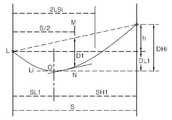
전술한 이도 산출 과정은 전선 지지점의 높이가 동일한 경우로서, 이를 도면으로 간략히 나타내면 도 6과 같다. 도 6에서 S는 제1 철탑 또는 제1 철탑의 전선 지지점(A)과 제2 철탑 또는 제2 철탑의 전선 지지점(B) 사이의 경간을 나타내고, D1은 전선의 이도를 나타낸다. 그리고, T1은 전선의 최대 수평 장력을 나타낸다.The above-described idle calculation process is the case where the height of the wire support points is the same. 6, S represents a span between a wire supporting point A of the first steel tower or the first steel tower and a wire supporting point B of the second steel tower or the second steel tower, and D1 represents a conductor of the wire. T1 represents the maximum horizontal tension of the wire.
한편, 전선 지지점 간의 고저차를 고려한 가공철탑전선의 이도 산출 과정을 나타내면 도 7의 모식도와 같다.7 is a schematic view showing the process of calculating the idle length of a machined steel tower cable in consideration of the difference in level between the support points of the wire.
도 7에 도시한 바와 같이, 전선 지지점의 높이가 상이하면, 전선의 이도가 하기 수학식 4에 의하여 계산되고, 전선의 실장은 하기 수학식 5에 의하여 계산될 수 있다.
As shown in Fig. 7, if the heights of the wire fulcrums are different, the curve of the wire can be calculated by the following equation (4), and the mounting of the wire can be calculated by the following equation (5).


수학식 5에서, L은 전선의 실장, S는 철탑 중심들(H, L) 사이의 거리인 수평경간, D는 초기 가선 이도이다. 그리고, h는 전선 지지점의 고저차로서 자기 지지점에서 상대 지지점이 높으면 포지티브 값을 갖고, 낮으면 네거티브 값을 갖는다.In Equation (5), L is the mounting of the wire, S is the horizontal span, which is the distance between the centers of the steel tower (H, L), and D is the initial curvature. And, h is a height difference of the wire supporting point, and has a positive value when the relative supporting point is high at its own supporting point, and has a negative value when it is low.
또한, 상기 수학식 5에서, DH1,DL1은 최악조건 하에서 지지점 H와 L로부터 최저점 0까지의 각각의 이도를 나타내고, SH1, SL1은 H 또는 L 지지점으로부터 0점까지의 각각의 수평거리를 나타내며, h는 H와 L점의 고저차를 나타내고, D1은 경간 S에서 고저차가 없을 때의 이도를 나타낸다.In Equation (5), DH1 and DL1 represent the respective degrees of support from the supporting points H and L to the lowest point 0 under the worst condition, and SH1 and SL1 represent the horizontal H represents the height difference between the points H and L, and D1 represents the distance when there is no difference in height between the spans S.
본 발명의 실시예에 의하면, 최악조건 온도에서의 이도를 산정하고, 최악조건 이도를 바탕으로 변화된 이도에 맞는 변경 피라미터를 계산하여, 최악 조건에 요구되는 실장을 구할 수 있으며, 최악 조건의 이도에 맞는 최대허용장력을 산출할 수 있다.According to the embodiment of the present invention, it is possible to calculate the deviation at the worst condition temperature, calculate the change pitch meter corresponding to the changed idle condition based on the worst condition condition, obtain the required mounting condition for the worst condition, It is possible to calculate the maximum permissible tension suitable for the above.
도 8은 본 발명에서 사용되는 지상라이다(100)를 도시한 평면도이다. 상기 지상라이다(100)는 초점 조절 모듈(110), 마운트(120) 및 정렬 모듈(130)을 포함하여 이루어질 수 있다. 상기 초점 조절 모듈(110)은 광원에 연결되고, 상기 광원으로부터 조사되는 레이저의 초점을 조절할 수 있는 장치이며, 상기 마운트(120)는 상기 초점 조절 모듈(110)과 연결되고, 상기 광원을 고정하는 역할을 할 수 있다. 상기 정렬 모듈(130)은 상기 광원과 라이더에 포함된 망원 장치(미도시)와의 정렬을 실시할 수 있도록 하는 장치이다. 한편, 본 명세서에서 도시되지 않았지만 상기 지상라이다는 콘트롤러(미도시)와 연결될 수 있다. 상기 콘크롤러는 전류의 세기를 조절함으로써, 광원에서 조사되는 레이저의 세기를 가변적으로 조절할 수 있도록 할 수 있다.FIG. 8 is a plan view showing a
이상과 같이, 본 발명은 비록 한정된 실시예와 도면에 의해 설명되었으나, 본 발명은 이것에 의해 한정되지 않으며, 본 발명이 속하는 기술분야에서 통상의 지식을 가진 자에 의하여 본 발명의 기술사상과 아래에 기재될 특허청구범위의 균등범위 내에서 다양한 수정 및 변형이 가능함은 물론이다.While the present invention has been particularly shown and described with reference to exemplary embodiments thereof, it is to be understood that the invention is not limited to the disclosed exemplary embodiments, It will be understood by those skilled in the art that various changes in form and details may be made therein without departing from the spirit and scope of the invention.
100 : 지상라이다 120 : 마운트
110 : 초점 조절 모듈 130 : 정렬 모듈100: ground Raida 120: mount
110: focus adjustment module 130: alignment module
Claims (6)
Translated fromKorean(a) 지상라이다 측량 시스템으로 스캔데이터를 획득하는 단계(S11);
(b) 상기 단계(S11)에서 획득된 스캔데이터를 얼라인 작업으로 병합하는 단계(S12);
(c) 상기 단계(S12)에서 병합된 스캔데이터를 3차원 이미지의 점군데이터로 변환하는 단계(S13);
(d) 상기 단계(S13)의 점군데이터를 기초로 철탑 모델과 가공철탑전선 모델을 생성하는 단계(S14); 및
(e) 상기 단계(S14)의 철탑 모델과 가공철탑전선의 제1 이도를 산출하는 단계(S15);로 이루어지는 것을 특징으로 하는 지상라이다를 이용한 가공철탑전선의 이도, 실장 관측 및 산출방법.In the method of measuring and measuring the machined steel tower wire,
(a) acquiring scan data with a terrestrial lidar surveying system (S11);
(b) merging the scan data obtained in the step (S11) into an alignment operation (S12);
(c) converting the merged scan data into the point cloud data of the three-dimensional image in the step S12 (S13);
(d) generating (S14) a steel tower model and a working steel tower wire model based on the point cloud data in the step (S13); And
(e) calculating a first idle of the steel tower model and the machining steel tower wire in the step (S14); and (S15) calculating the first islands of the steel tower wire in the step (S14).
상기 (c)단계는, 스캔데이터에서 철탑 및 가공철탑전선을 샘플링(S131)하고, 상기 샘플링된 데이터의 깊이를 나타낸 이미지와 이를 색상으로 나타낸 이미지를 맵핑한 포인트 클라우드를 생성(S132)하며, 상기 포인트 클라우드에서 상기 철탑과 가공철탑전선을 모델링한 3차원 이미지가 추출(S133)되면서 불필요한 영역은 제거(S134)되는 것을 특징으로 하는 지상라이다를 이용한 가공철탑전선의 이도, 실장 관측 및 산출방법.The method according to claim 1,
In step (c), the steel tower and the steel tower wire are sampled from the scan data (S131), and a point cloud in which an image representing the depth of the sampled data is mapped to an image representing the depth of the sampled data is generated (S132) A three-dimensional image modeled by the steel tower and a machining steel tower wire is extracted in a point cloud (S133), and an unnecessary area is removed (S134), and a method of observing and calculating a machining steel tower wire using the ground wire.
상기 (e)단계는, 철탑 모델에서 획득한 철탑의 지반고와 가공철탑전선 모델에서 획득한 복수의 이도 측량 지점을 동일 평면 상에 배열하는 단계;
상기 단계에서 이도 측량 지점의 고저차에 따라 철탑 모델에서 획득한 철탑과 이도 측량 지점을 단일 곡선 형태로 연결하는 제1 피라미터를 부가하는 단계; 및
상기 단계의 철탑과 제1 피라미터를 토대로 현재의 온도에서의 제1 이도를 계산하는 단계;로 이루어지는 것을 특징으로 하는 지상라이다를 이용한 가공철탑전선의 이도, 실장 관측 및 산출방법.The method according to claim 1,
Wherein the step (e) includes the steps of: arranging, on the same plane, a plurality of earing survey points obtained in the steel tower wire model obtained from the steel tower model obtained from the steel tower model;
Adding a first pyrameter connecting the pylon and the earing point obtained in the pylon model according to the elevation difference of the earing survey point in a single curve form; And
And calculating a first angle at a current temperature based on the steel tower and the first pyrameter at the current temperature.
상기 (e)단계 이후에, 제1 이도를 바탕으로 최악조건의 온도에서 변화이도를 구하여 변경 피라미터를 계산하고, 상기 변경 피라미터를 토대로 최악조건에서의 실장을 산출하는 단계(S16);를 더 포함하는 것을 특징으로 하는 지상라이다를 이용한 가공철탑전선의 이도, 실장 관측 및 산출방법.4. The method according to any one of claims 1 to 3,
Calculating a change petrameter by calculating a change map at a temperature of the worst condition on the basis of the first map, calculating a mount under the worst condition based on the change pyrameter (S16); And the method further comprises the steps of: measuring the surface of the wire rod;
상기 (e)단계 이후에, 제1 이도, 전선 지지점의 고저차 및 경간을 이용하여 상기 가공철탑전선의 최악조건 실장을 산출하는 단계;를 더 포함하는 것을 특징으로 하는 지상라이다를 이용한 가공철탑전선의 이도, 실장 관측 및 산출방법.4. The method according to any one of claims 1 to 3,
Further comprising the step of calculating a worse condition mounting of the working steel tower wire by using the first angle, the elevation difference and the span of the wire supporting point after the step (e). And observing and calculating method.
상기 지상라이다 측량시스템은 300nm 내지 535nm 중심파장의 레이저를 발진하고, 접속된 콘트롤러에 의해 작동이 제어되며, 광원에 연결되고 상기 광원으로부터 조사되는 레이저의 초점을 조절하는 초점 조절 모듈(110)과 상기 초점 조절 모듈(110)과 연결되며, 상기 광원을 고정하는 마운트(120)와 상기 광원과 측정거리와의 정렬을 가능케하는 정렬 모듈(130)로 구성되는 것을 특징으로 하는 지상라이다를 이용한 가공철탑전선의 이도, 실장 관측 및 산출방법.
The method according to claim 1,
The terrestrial laser measurement system includes a focus adjustment module 110 for controlling the focus of a laser beam emitted from the light source and oscillating a laser having a center wavelength of 300 to 535 nm, And a alignment module (130) connected to the focus adjustment module (110), the mount (120) fixing the light source and the alignment distance between the light source and the measurement distance. Tracking, mounting observations and calculation methods of steel tower wires.
Priority Applications (2)
| Application Number | Priority Date | Filing Date | Title |
|---|---|---|---|
| KR1020150083087AKR101552589B1 (en) | 2015-06-12 | 2015-06-12 | Method for measuring overhead transmission line and calculating dig and actual tension thereof using ground light detection and ranging |
| PCT/KR2016/006155WO2016200192A1 (en) | 2015-06-12 | 2016-06-10 | Apparatus and method for measuring dipping and mounting of overhead steel tower transmission line using terrestrial lidar |
Applications Claiming Priority (1)
| Application Number | Priority Date | Filing Date | Title |
|---|---|---|---|
| KR1020150083087AKR101552589B1 (en) | 2015-06-12 | 2015-06-12 | Method for measuring overhead transmission line and calculating dig and actual tension thereof using ground light detection and ranging |
Publications (1)
| Publication Number | Publication Date |
|---|---|
| KR101552589B1true KR101552589B1 (en) | 2015-09-14 |
Family
ID=54248106
Family Applications (1)
| Application Number | Title | Priority Date | Filing Date |
|---|---|---|---|
| KR1020150083087AActiveKR101552589B1 (en) | 2015-06-12 | 2015-06-12 | Method for measuring overhead transmission line and calculating dig and actual tension thereof using ground light detection and ranging |
Country Status (2)
| Country | Link |
|---|---|
| KR (1) | KR101552589B1 (en) |
| WO (1) | WO2016200192A1 (en) |
Cited By (13)
| Publication number | Priority date | Publication date | Assignee | Title |
|---|---|---|---|---|
| CN105674895A (en)* | 2016-04-19 | 2016-06-15 | 福州大学 | Non-linear dynamic strain calculation method of non-contact measuring stay cable |
| KR101995898B1 (en)* | 2019-03-20 | 2019-07-04 | (주)선운이앤지 | Method for calculating dip of aerial transmission line using electric wire survey and program |
| WO2019147965A1 (en)* | 2018-01-26 | 2019-08-01 | LineVision, Inc. | System and method for power transmission line monitoring |
| KR102110339B1 (en) | 2020-01-31 | 2020-05-14 | (주)선운이앤지 | Three-dimensional line spacing review method using overhead transmission line |
| KR20200056028A (en)* | 2018-11-14 | 2020-05-22 | 한국전력공사 | Apparatus estimating sag for power transmission line |
| KR102210344B1 (en)* | 2020-07-09 | 2021-02-01 | 주식회사 우리아이씨티 | Method for producing digital topography using 3D precision scanner-based field survey and complementary survey |
| KR20210036806A (en)* | 2019-09-26 | 2021-04-05 | (주)선운이앤지 | System for selecting transmission line status using GIS |
| WO2021079433A1 (en)* | 2019-10-23 | 2021-04-29 | 日本電信電話株式会社 | Computation device, facility management method, and program |
| KR20210144003A (en)* | 2020-05-21 | 2021-11-30 | 한국전력공사 | Apparatus and method for measuring dip of power line using drone |
| WO2023277657A1 (en)* | 2021-07-02 | 2023-01-05 | 김동철 | Transmission line construction method using wire pulling and wire tensioning |
| CN119063648A (en)* | 2024-11-01 | 2024-12-03 | 四川中水成勘院工程物探检测有限公司 | A displacement measurement method and system for concrete arch dam |
| CN119919706A (en)* | 2024-12-05 | 2025-05-02 | 华南理工大学 | A classification monitoring method and electronic equipment for insulator equivalent ice thickness |
| CN119919706B (en)* | 2024-12-05 | 2025-10-10 | 华南理工大学 | Insulator equivalent ice thickness classification monitoring method and electronic equipment |
Families Citing this family (3)
| Publication number | Priority date | Publication date | Assignee | Title |
|---|---|---|---|---|
| CN111583174B (en)* | 2020-03-27 | 2022-09-06 | 武汉地大信息工程股份有限公司 | Method and system for deformation detection and detection of iron tower based on point cloud data |
| CN115841568B (en)* | 2023-02-16 | 2023-04-21 | 北京华科智行科技有限公司 | Method for reconstructing transmission tower insulator based on standing book data |
| CN118463003A (en)* | 2024-07-10 | 2024-08-09 | 广东电网有限责任公司江门供电局 | Laser radar fixing device and laser radar system |
Citations (1)
| Publication number | Priority date | Publication date | Assignee | Title |
|---|---|---|---|---|
| US20140123750A1 (en) | 2011-06-10 | 2014-05-08 | State Grid Information & Telecommunication Branch | Method and system for monitoring power transmission line of power grid |
Family Cites Families (4)
| Publication number | Priority date | Publication date | Assignee | Title |
|---|---|---|---|---|
| KR100694444B1 (en)* | 2005-07-15 | 2007-03-12 | 한국전력공사 | Direct survey method for wire dip |
| KR101007503B1 (en)* | 2008-12-03 | 2011-01-12 | 한전케이피에스 주식회사 | Transmission Line Determination Method |
| KR101403674B1 (en)* | 2012-12-17 | 2014-06-10 | 한전케이피에스 주식회사 | System for Safety distance analysis of transmission lines and method therefor |
| KR101512800B1 (en)* | 2014-11-24 | 2015-04-20 | (주)케이지에스테크 | Indicators through field observations of topography and altitude information based on digital map data verification method applied to the system |
- 2015
- 2015-06-12KRKR1020150083087Apatent/KR101552589B1/enactiveActive
- 2016
- 2016-06-10WOPCT/KR2016/006155patent/WO2016200192A1/ennot_activeCeased
Patent Citations (1)
| Publication number | Priority date | Publication date | Assignee | Title |
|---|---|---|---|---|
| US20140123750A1 (en) | 2011-06-10 | 2014-05-08 | State Grid Information & Telecommunication Branch | Method and system for monitoring power transmission line of power grid |
Cited By (21)
| Publication number | Priority date | Publication date | Assignee | Title |
|---|---|---|---|---|
| CN105674895A (en)* | 2016-04-19 | 2016-06-15 | 福州大学 | Non-linear dynamic strain calculation method of non-contact measuring stay cable |
| WO2019147965A1 (en)* | 2018-01-26 | 2019-08-01 | LineVision, Inc. | System and method for power transmission line monitoring |
| EP3743683B1 (en)* | 2018-01-26 | 2024-10-16 | Linevision, Inc. | System and method for power transmission line monitoring |
| US11835570B2 (en) | 2018-01-26 | 2023-12-05 | LineVision, Inc. | System and method for power transmission line monitoring |
| US10948531B2 (en) | 2018-01-26 | 2021-03-16 | LineVision, Inc. | System and method for power transmission line monitoring |
| KR20200056028A (en)* | 2018-11-14 | 2020-05-22 | 한국전력공사 | Apparatus estimating sag for power transmission line |
| KR102172543B1 (en)* | 2018-11-14 | 2020-11-03 | 한국전력공사 | Apparatus estimating sag for power transmission line |
| KR101995898B1 (en)* | 2019-03-20 | 2019-07-04 | (주)선운이앤지 | Method for calculating dip of aerial transmission line using electric wire survey and program |
| KR20210036806A (en)* | 2019-09-26 | 2021-04-05 | (주)선운이앤지 | System for selecting transmission line status using GIS |
| KR102285667B1 (en)* | 2019-09-26 | 2021-08-04 | (주)선운이앤지 | System for selecting transmission line status using GIS |
| JPWO2021079433A1 (en)* | 2019-10-23 | 2021-04-29 | ||
| WO2021079433A1 (en)* | 2019-10-23 | 2021-04-29 | 日本電信電話株式会社 | Computation device, facility management method, and program |
| JP7184207B2 (en) | 2019-10-23 | 2022-12-06 | 日本電信電話株式会社 | Arithmetic device, facility management method, and program |
| KR102110339B1 (en) | 2020-01-31 | 2020-05-14 | (주)선운이앤지 | Three-dimensional line spacing review method using overhead transmission line |
| KR20210144003A (en)* | 2020-05-21 | 2021-11-30 | 한국전력공사 | Apparatus and method for measuring dip of power line using drone |
| KR102356916B1 (en)* | 2020-05-21 | 2022-02-03 | 한국전력공사 | Apparatus and method for measuring dip of power line using drone |
| KR102210344B1 (en)* | 2020-07-09 | 2021-02-01 | 주식회사 우리아이씨티 | Method for producing digital topography using 3D precision scanner-based field survey and complementary survey |
| WO2023277657A1 (en)* | 2021-07-02 | 2023-01-05 | 김동철 | Transmission line construction method using wire pulling and wire tensioning |
| CN119063648A (en)* | 2024-11-01 | 2024-12-03 | 四川中水成勘院工程物探检测有限公司 | A displacement measurement method and system for concrete arch dam |
| CN119919706A (en)* | 2024-12-05 | 2025-05-02 | 华南理工大学 | A classification monitoring method and electronic equipment for insulator equivalent ice thickness |
| CN119919706B (en)* | 2024-12-05 | 2025-10-10 | 华南理工大学 | Insulator equivalent ice thickness classification monitoring method and electronic equipment |
Also Published As
| Publication number | Publication date |
|---|---|
| WO2016200192A1 (en) | 2016-12-15 |
Similar Documents
| Publication | Publication Date | Title |
|---|---|---|
| KR101552589B1 (en) | Method for measuring overhead transmission line and calculating dig and actual tension thereof using ground light detection and ranging | |
| CN111121645B (en) | High-precision overhead transmission conductor sag detection method | |
| US20140132723A1 (en) | Methods for calibrating a digital photographic image of utility structures | |
| KR101552585B1 (en) | Analysis and calculation of horizontal distance and horizontal distance and structures of overhead transmission lines using lidar | |
| CN105244805A (en) | Laser radar-based intelligent early-warning evaluation method and system for power transmission line | |
| CN110472477B (en) | Method for monitoring icing by carrying infrared camera by RTK unmanned aerial vehicle | |
| CN112115588B (en) | Multi-working-condition simulation analysis method for power transmission line channel | |
| KR102110339B1 (en) | Three-dimensional line spacing review method using overhead transmission line | |
| CN104122560B (en) | Electric transmission line wide area ice condition monitoring method | |
| JP7098349B2 (en) | Wire shape reproduction method, reproduction device, and reproduction program, as well as point cloud accuracy evaluation method, evaluation device, and evaluation program. | |
| CN111047542B (en) | Power line point supplementing method | |
| CN103791894A (en) | Tower positioning method and device for overhead power transmission line | |
| KR101470981B1 (en) | Method for Analysis and Measurement of Displacement of Power Transmission Tower Using Ground Light Detection and Ranging | |
| CN111243083A (en) | Three-dimensional modeling method based on unmanned aerial vehicle oblique photogrammetry technology | |
| Ussyshkin et al. | Advantages of airborne lidar technology in power line asset management | |
| CN103363952A (en) | Vehicle-mounted photoelectric measuring device and method for target sizes and interval between electric transmission line and target | |
| CN116989681A (en) | Wire sag on-line monitoring method for power transmission line | |
| CN118570166B (en) | Method for determining galloping monitoring point of power transmission wire, method for quantitatively analyzing galloping monitoring, and method and device for controlling galloping monitoring | |
| CN112419284A (en) | Sag Measurement Method Based on Partial Image of Transmission Line | |
| CN111402447A (en) | Power grid line inspection method, server, system and storage medium | |
| CN107885229A (en) | A kind of unmanned plane and its electric power line inspection method of achievable power line automatic detecting | |
| KR101995898B1 (en) | Method for calculating dip of aerial transmission line using electric wire survey and program | |
| CN111222236A (en) | A method and analyzer for calculating the cutting length of flexible conductors in substations | |
| JP2002174510A (en) | System for measuring distance of body near transmission lines | |
| CN116886741A (en) | A power cable construction trench environment monitoring and early warning system |
Legal Events
| Date | Code | Title | Description |
|---|---|---|---|
| PA0109 | Patent application | St.27 status event code:A-0-1-A10-A12-nap-PA0109 | |
| PA0201 | Request for examination | St.27 status event code:A-1-2-D10-D11-exm-PA0201 | |
| PA0302 | Request for accelerated examination | St.27 status event code:A-1-2-D10-D17-exm-PA0302 St.27 status event code:A-1-2-D10-D16-exm-PA0302 | |
| E701 | Decision to grant or registration of patent right | ||
| PE0701 | Decision of registration | St.27 status event code:A-1-2-D10-D22-exm-PE0701 | |
| GRNT | Written decision to grant | ||
| PR0701 | Registration of establishment | St.27 status event code:A-2-4-F10-F11-exm-PR0701 | |
| PR1002 | Payment of registration fee | St.27 status event code:A-2-2-U10-U11-oth-PR1002 Fee payment year number:1 | |
| PG1601 | Publication of registration | St.27 status event code:A-4-4-Q10-Q13-nap-PG1601 | |
| P14-X000 | Amendment of ip right document requested | St.27 status event code:A-5-5-P10-P14-nap-X000 | |
| P22-X000 | Classification modified | St.27 status event code:A-4-4-P10-P22-nap-X000 | |
| R18-X000 | Changes to party contact information recorded | St.27 status event code:A-5-5-R10-R18-oth-X000 | |
| P14-X000 | Amendment of ip right document requested | St.27 status event code:A-5-5-P10-P14-nap-X000 | |
| P14-X000 | Amendment of ip right document requested | St.27 status event code:A-5-5-P10-P14-nap-X000 | |
| FPAY | Annual fee payment | Payment date:20181008 Year of fee payment:4 | |
| PR1001 | Payment of annual fee | St.27 status event code:A-4-4-U10-U11-oth-PR1001 Fee payment year number:4 | |
| FPAY | Annual fee payment | Payment date:20191010 Year of fee payment:5 | |
| PR1001 | Payment of annual fee | St.27 status event code:A-4-4-U10-U11-oth-PR1001 Fee payment year number:5 | |
| P14-X000 | Amendment of ip right document requested | St.27 status event code:A-5-5-P10-P14-nap-X000 | |
| P14-X000 | Amendment of ip right document requested | St.27 status event code:A-5-5-P10-P14-nap-X000 | |
| P14-X000 | Amendment of ip right document requested | St.27 status event code:A-5-5-P10-P14-nap-X000 | |
| P14-X000 | Amendment of ip right document requested | St.27 status event code:A-5-5-P10-P14-nap-X000 | |
| PR1001 | Payment of annual fee | St.27 status event code:A-4-4-U10-U11-oth-PR1001 Fee payment year number:6 | |
| P14-X000 | Amendment of ip right document requested | St.27 status event code:A-5-5-P10-P14-nap-X000 | |
| S20-X000 | Security interest recorded | St.27 status event code:A-4-4-S10-S20-lic-X000 | |
| P22-X000 | Classification modified | St.27 status event code:A-4-4-P10-P22-nap-X000 | |
| PR1001 | Payment of annual fee | St.27 status event code:A-4-4-U10-U11-oth-PR1001 Fee payment year number:7 | |
| P14-X000 | Amendment of ip right document requested | St.27 status event code:A-5-5-P10-P14-nap-X000 | |
| PR1001 | Payment of annual fee | St.27 status event code:A-4-4-U10-U11-oth-PR1001 Fee payment year number:8 | |
| P14-X000 | Amendment of ip right document requested | St.27 status event code:A-5-5-P10-P14-nap-X000 | |
| P14-X000 | Amendment of ip right document requested | St.27 status event code:A-5-5-P10-P14-nap-X000 | |
| P14-X000 | Amendment of ip right document requested | St.27 status event code:A-5-5-P10-P14-nap-X000 | |
| P14-X000 | Amendment of ip right document requested | St.27 status event code:A-5-5-P10-P14-nap-X000 | |
| PR1001 | Payment of annual fee | St.27 status event code:A-4-4-U10-U11-oth-PR1001 Fee payment year number:9 | |
| P14-X000 | Amendment of ip right document requested | St.27 status event code:A-5-5-P10-P14-nap-X000 | |
| P14-X000 | Amendment of ip right document requested | St.27 status event code:A-5-5-P10-P14-nap-X000 | |
| P14-X000 | Amendment of ip right document requested | St.27 status event code:A-5-5-P10-P14-nap-X000 | |
| PR1001 | Payment of annual fee | St.27 status event code:A-4-4-U10-U11-oth-PR1001 Fee payment year number:10 | |
| R18-X000 | Changes to party contact information recorded | St.27 status event code:A-5-5-R10-R18-oth-X000 | |
| P14-X000 | Amendment of ip right document requested | St.27 status event code:A-5-5-P10-P14-nap-X000 | |
| P14-X000 | Amendment of ip right document requested | St.27 status event code:A-5-5-P10-P14-nap-X000 | |
| P14-X000 | Amendment of ip right document requested | St.27 status event code:A-5-5-P10-P14-nap-X000 | |
| P14-X000 | Amendment of ip right document requested | St.27 status event code:A-5-5-P10-P14-nap-X000 | |
| P14-X000 | Amendment of ip right document requested | St.27 status event code:A-5-5-P10-P14-nap-X000 | |
| PR1001 | Payment of annual fee | St.27 status event code:A-4-4-U10-U11-oth-PR1001 Fee payment year number:11 |