KR101543272B1 - Deposition device with vaporizer - Google Patents
Deposition device with vaporizerDownload PDFInfo
- Publication number
- KR101543272B1 KR101543272B1KR1020070138779AKR20070138779AKR101543272B1KR 101543272 B1KR101543272 B1KR 101543272B1KR 1020070138779 AKR1020070138779 AKR 1020070138779AKR 20070138779 AKR20070138779 AKR 20070138779AKR 101543272 B1KR101543272 B1KR 101543272B1
- Authority
- KR
- South Korea
- Prior art keywords
- vaporizer
- gas
- source material
- source
- process chamber
- Prior art date
- Legal status (The legal status is an assumption and is not a legal conclusion. Google has not performed a legal analysis and makes no representation as to the accuracy of the status listed.)
- Active
Links
Images


Classifications
- C—CHEMISTRY; METALLURGY
- C23—COATING METALLIC MATERIAL; COATING MATERIAL WITH METALLIC MATERIAL; CHEMICAL SURFACE TREATMENT; DIFFUSION TREATMENT OF METALLIC MATERIAL; COATING BY VACUUM EVAPORATION, BY SPUTTERING, BY ION IMPLANTATION OR BY CHEMICAL VAPOUR DEPOSITION, IN GENERAL; INHIBITING CORROSION OF METALLIC MATERIAL OR INCRUSTATION IN GENERAL
- C23C—COATING METALLIC MATERIAL; COATING MATERIAL WITH METALLIC MATERIAL; SURFACE TREATMENT OF METALLIC MATERIAL BY DIFFUSION INTO THE SURFACE, BY CHEMICAL CONVERSION OR SUBSTITUTION; COATING BY VACUUM EVAPORATION, BY SPUTTERING, BY ION IMPLANTATION OR BY CHEMICAL VAPOUR DEPOSITION, IN GENERAL
- C23C16/00—Chemical coating by decomposition of gaseous compounds, without leaving reaction products of surface material in the coating, i.e. chemical vapour deposition [CVD] processes
- C23C16/44—Chemical coating by decomposition of gaseous compounds, without leaving reaction products of surface material in the coating, i.e. chemical vapour deposition [CVD] processes characterised by the method of coating
- C23C16/448—Chemical coating by decomposition of gaseous compounds, without leaving reaction products of surface material in the coating, i.e. chemical vapour deposition [CVD] processes characterised by the method of coating characterised by the method used for generating reactive gas streams, e.g. by evaporation or sublimation of precursor materials
- C—CHEMISTRY; METALLURGY
- C23—COATING METALLIC MATERIAL; COATING MATERIAL WITH METALLIC MATERIAL; CHEMICAL SURFACE TREATMENT; DIFFUSION TREATMENT OF METALLIC MATERIAL; COATING BY VACUUM EVAPORATION, BY SPUTTERING, BY ION IMPLANTATION OR BY CHEMICAL VAPOUR DEPOSITION, IN GENERAL; INHIBITING CORROSION OF METALLIC MATERIAL OR INCRUSTATION IN GENERAL
- C23C—COATING METALLIC MATERIAL; COATING MATERIAL WITH METALLIC MATERIAL; SURFACE TREATMENT OF METALLIC MATERIAL BY DIFFUSION INTO THE SURFACE, BY CHEMICAL CONVERSION OR SUBSTITUTION; COATING BY VACUUM EVAPORATION, BY SPUTTERING, BY ION IMPLANTATION OR BY CHEMICAL VAPOUR DEPOSITION, IN GENERAL
- C23C16/00—Chemical coating by decomposition of gaseous compounds, without leaving reaction products of surface material in the coating, i.e. chemical vapour deposition [CVD] processes
Landscapes
- Chemical & Material Sciences (AREA)
- General Chemical & Material Sciences (AREA)
- Chemical Kinetics & Catalysis (AREA)
- Engineering & Computer Science (AREA)
- Materials Engineering (AREA)
- Mechanical Engineering (AREA)
- Metallurgy (AREA)
- Organic Chemistry (AREA)
- Chemical Vapour Deposition (AREA)
Abstract
Translated fromKoreanDescription
Translated fromKorean본 발명은 기화기를 가지는 증착장치에 관한 것으로, 보다 구체적으로 기화기에 반응가스 또는 용제를 공급하여, 액체상태의 소오스 물질의 기화효율을 증가시킨 기화기를 가지는 증착장치에 관한 것이다.BACKGROUND OF THE INVENTION 1. Field of the Invention The present invention relates to a vapor deposition apparatus having a vaporizer, and more particularly, to a vapor deposition apparatus having a vaporizer in which a vaporization efficiency of a source material in a liquid state is increased by supplying a reactive gas or a solvent to a vaporizer.
일반적으로 물질을 박막 형태로 형성하는 방법은 물리적 충돌을 이용하는 스퍼터링 방법과, 기상의 원료가스를 공급하는 증착방법으로 구분된다. 반도체 소자의 고집적화에 따라 조성 및 두께의 균일도와 단차 피복성이 우수한, 기상증착방법을 선호한다. 상기와 같은 기상증착방법은 박막을 형성하는 데 필요한 소오스 가스을 기판이 안착된 반응챔버에 공급함으로써 기판 상에 원하는 박막을 증착하는 방식이다. 그러나 박막형성에 사용되는 소오스 물질이 기체상태가 아닌 액체상태로 존재하는 경우에, 액체상태의 소오스 물질을 기화시킨 후에 반응챔버의 내부의 기판의 표면까지 이송하게 된다. 따라서 반응챔버의 소오스 물질 주입구 근처까지는 소오스 물질을 액체상태로 공급하고, 기화기를 통하여 액체상태의 소오스 물질을 기화시켜 소오스 가스로 공급하는 방법을 사용한다.Generally, a method of forming a material into a thin film is classified into a sputtering method using physical impact and a deposition method of supplying a raw material gas in a gaseous phase. A vapor deposition method is preferred, which is superior in uniformity of composition and thickness, and step coverage as a semiconductor device is highly integrated. In the vapor deposition method, a desired thin film is deposited on a substrate by supplying a source gas necessary for forming a thin film to a reaction chamber on which the substrate is placed. However, in the case where the source material used for forming the thin film exists in a liquid state instead of a gaseous state, the liquid source material is vaporized and then transported to the surface of the substrate inside the reaction chamber. Therefore, the source material is supplied in a liquid state to the vicinity of the source material inlet of the reaction chamber, and the source material in a liquid state is vaporized through the vaporizer to supply the source gas to the source gas.
그런데, 종래의 기화기는 액상의 소스물질이 완전하게 기화되지 않고, 액체상태와 기체상태의 소오스 물질이 반응챔버에 유입되어 박막 증착 공정을 진행하게 된다. 반응챔버에 유입된 액체상태의 소오스 물질로 인해, 증착박막의 균일성이 저하되거나, 또는 증착박막에 이물질(particle)이 발생하게 된다.However, in the conventional vaporizer, the liquid source material is not completely vaporized, and the source material in the liquid state and the gaseous state flows into the reaction chamber, and the thin film deposition process proceeds. The uniformity of the deposited thin film may be lowered or particles may be generated in the deposited thin film due to the source material in the liquid state flowing into the reaction chamber.
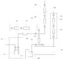
이하에서, 도 1를 참조하여 종래기술의 기화기를 사용하는 증착장치를 설명하면 다음과 같다. 도 1은 종래기술에 따른 기화기를 사용하는 증착장치의 개략도이다.Hereinafter, a vapor deposition apparatus using a conventional vaporizer will be described with reference to FIG. 1 is a schematic view of a vapor deposition apparatus using a vaporizer according to the prior art.
종래기술에서, 기화기가 설치되는 증착장치는, 기판(도시하지 않음) 상에 박막이 증착시키는 공정을 진행하는 공정챔버(10)와, 액체상태의 소오스 물질(12)을 공정챔버(10)에 공급하기 위한 소오스 공급부(14)와, 소오스 물질(12)을 기체 상태로 변환시켜 공정챔버(10)의 내부로 공급하는 기화기(16)와, 공정챔버(10)에 반응가스를 공급하기 위한 반응가스 공급부(52)와, 액체상태의 소오스 물질(12)을 기화기(16)로 이송시키기 위한 캐리어 가스 공급부(42)로 구성된다.In the prior art, a deposition apparatus in which a vaporizer is installed includes a
공정챔버(10)는 박막증착 공정이 진행되도록 진공상태를 유지할 수 있는 밀폐공간이고, 도면에는 도시하지 않았지만 내부공간에는 기판이 안착되는 기판 안치 대와 소오스 가스 및 반응가스를 분배시키는 분배장치가 마련되어 있다. 소오스 공급부(14)는 액체 상태의 소오스 물질(12)이 저장되는 저장탱크(18)와, 소오스 물질(12)을 저장탱크(18)에 공급하는 소오스 물질 공급원(도시되지 않음)과, 저장탱크(18)의 내부에서 소오스 물질(12)을 기화기(16)에 공급될 수 있도록 Ar과 같은 제 1 캐리어 가스를 공급하는 제 1 캐리어 가스 공급원(도시되지 않음)과, 액체 상태의 소오스 물질(12)의 유량을 제어하는 제 1 유량제어기(MFC)(50)로 구성된다.The
기화기(16)와 연결되는 캐리어 가스 공급부(42)는 기화기(16)에서 기체 상태로 변환된 소오스 물질을 공급배관을 따라 공정챔버(10)로 공급하기 위한 Ar과 같은 제 2 캐리어 가스 공급원(도시되지 않음)과, 제 2 캐리어 가스의 유량을 제어하는 제 2 유량제어기(MFC)(20)와, 제 2 캐리어 가스를 가열하는 제 1 가열기(22)를 포함한다. 그리고, 공정챔버(10)에는 공급유량이 안정되지 않은 제 2 캐리어 가스를 공정챔버(10)로 공급하지 않고 펌핑 라인(pumping line)(26)을 통하여 트랩장치(24)로 공급한다. 트랩장치(24)에는 진공펌프(도시하지 않음)가 연결된다.A
공정챔버(10)에 반응가스를 공급하기 위한 반응가스 공급부(52)는 반응가스 공급원(도시하지 않음)과, 반응가스의 유량을 제어하기 위한 제 3 유량제어기(MFC)(54)와, 반응가스를 가열하기 위한 제 2 가열기(56)를 포함한다. 기화기(16)와 펌핑 라인(26) 사이 및 기화기(16)와 가열기(22) 사이 등에는 필요에 따른 밸브를 장착하여 사용한다.A reaction
도 1과 같은 증착장치에서, 액체상태의 소오스 물질로 루테늄(Ru)을 포함한 소오스와 제 1 및 제 2 캐리어 가스로 아르곤(Ar)을 사용하고, 루테늄과 반응하는 반응가스로 산소(O2) 또는 오존(O3)을 사용하여, 루테늄 산화막(RuO2)을 기판 상에 증착한다. 그런데, 루테늄를 포함한 액체상태의 소오스를 기화기(16)에서 100 내지 190℃의 온도에서 기화시켜 공정챔버(10)에 공급하지만 기화효율이 낮아 기판 상에 증착되는 박막에서 헤이즈(Haze) 또는 브리스터(Blister)의 불량이 발생한다.1, argon (Ar) is used as a source including ruthenium (Ru) and first and second carrier gases as a source material in a liquid state, and oxygen (O2) or A ruthenium oxide film (RuO2 ) is deposited on the substrate using ozone (O 3). A liquid source including ruthenium is vaporized in the
상기와 같은 종래기술의 문제를 해결하기 위하여, 본 발명은 기화기에서 소오스 물질과 반응가스의 불완전 반응상태로 기화시키고, 공정챔버에서 소오스 물질과 반응가스의 완전한 반응에 의해 기판 상에 양질의 박막을 증착하는 기화기를 가지는 증착장치를 제공하는 것을 목적으로 한다.In order to solve the problems of the prior art as described above, the present invention provides a method for vaporizing a source material and a reactive gas in an incomplete reaction state in a vaporizer, And to provide a vapor deposition apparatus having a vaporizer for vapor deposition.
본 발명은 기화기에 소오스 물질과 용제를 공급하여, 소오스 물질의 기화효율을 증가시킨 기화기를 가지는 증착장치를 제공하는 것을 다른 목적으로 한다.Another object of the present invention is to provide a vapor deposition apparatus having a vaporizer in which a source material and a solvent are supplied to a vaporizer to increase the vaporization efficiency of the source material.
상기 목적을 달성하기 위한 본 발명에 따른 기화기를 가지는 증착장치는, 액체상태의 소오스 물질과 반응가스가 공급되어 불완전 반응상태의 혼합가스로 기화되는 기화기; 상기 기화기로부터 상기 혼합가스를 공급받아, 상기 소오스 물질과 상기 반응가스의 완전한 반응에 의해 기판 상에 박막을 증착시키는 공정챔버;를 포함하는 것을 특징으로 한다.According to an aspect of the present invention, there is provided a vapor deposition apparatus having a vaporizer, including: a vaporizer that is supplied with a source material in a liquid state and a reaction gas and is vaporized into a mixed gas in an incomplete reaction state; And a process chamber that receives the mixed gas from the vaporizer and deposits a thin film on the substrate by a complete reaction between the source material and the reactive gas.
상기와 같은 기화기를 가지는 증착장치에 있어서, 상기 소오스 물질은 루테늄을 포함한 유기 소오스이고, 상기 반응가스는 산소 또는 오존이고, 상기 박막은 루테늄 또는 루테늄 산화막인 것을 특징으로 한다.In the vapor deposition apparatus having the above-described vaporizer, the source material is an organic source including ruthenium, the reactive gas is oxygen or ozone, and the thin film is ruthenium or ruthenium oxide.
상기와 같은 기화기를 가지는 증착장치에 있어서, 상기 유기 소오스는 Ru[(C2H5)C5H4]2또는 Ru[(C7H11)(C7H9)]인 것을 특징으로 한다.In the vapor deposition apparatus having such a vaporizer, the organic source is characterized by being Ru [(C2 H5 ) C5 H4 ]2 or Ru [(C7 H11 ) (C7 H9 )] .
상기와 같은 기화기를 가지는 증착장치에 있어서, 상기 액체상태의 소오스 물질은 지르코늄(Zr) 또는 티타늄(Ti)를 포함하고, 상기 반응가스는 산소 또는 질소이고, 상기 박막은 지르코늄 산화막(ZrO2) 또는 티타늄 질화막(TiN)인 것을 특징으로 한다.In the deposition apparatus having a carburetor as described above, the source material in the liquid state comprises a zirconium (Zr) or titanium (Ti), and the reaction gas is oxygen or nitrogen, the thin film is zirconium oxide (ZrO2), or And is a titanium nitride film (TiN).
상기와 같은 기화기를 가지는 증착장치에 있어서, 상기 기화기 내부의 온도는 100 내지 200℃ 정도이고, 상기 공정챔버의 온도는 250 내지 500℃ 정도인 것을 특징으로 한다.In the vapor deposition apparatus having the above-described vaporizer, the temperature inside the vaporizer is about 100 to 200 ° C, and the temperature of the process chamber is about 250 to 500 ° C.
상기와 같은 기화기를 가지는 증착장치에 있어서, 상기 기화기에서 상기 혼합가스를 상기 공정챔버로 운반하기 위해 캐리어 가스를 사용하는 것을 특징으로 한다.In the vapor deposition apparatus having the above-described vaporizer, a carrier gas is used to transport the mixed gas from the vaporizer to the process chamber.
상기와 같은 목적을 달성하기 위한 기화기를 가지는 증착장치는 액체상태의 소오스 물질과 용제가 공급되어 상기 소오스 물질을 소오스 가스로 기화시키는 기화기; 반응가스를 공급하는 반응가스 공급부; 상기 기화기로부터 상기 소오스 가스와 상기 반응가스 공급부로부터 상기 반응가스를 공급받아 상기 소오스 가스와 상기 반응가스의 반응에 의해 기판 상에 박막을 증착시키는 공정챔버;를 포함하는 것을 특징으로 한다.According to an aspect of the present invention, there is provided a vapor deposition apparatus having a vaporizer, including: a vaporizer supplied with a liquid source material and a solvent to vaporize the source material into a source gas; A reaction gas supply unit for supplying a reaction gas; And a process chamber that receives the source gas and the reaction gas from the reaction gas supply unit from the vaporizer and deposits a thin film on the substrate by reaction between the source gas and the reaction gas.
상기와 같은 기화기를 가지는 증착장치에 있어서, 상기 소오스 물질은 루테늄을 포함한 유기 소오스이고, 상기 반응가스는 산소 또는 오존이고, 상기 박막은 루테늄 산화막이고, 상기 용제는 THF(TetraHydroFuran)과 같은 Alcohol계열 물질인 것을 특징으로 한다.In the vapor deposition apparatus having the above-described vaporizer, the source material is an organic source including ruthenium, the reactive gas is oxygen or ozone, the thin film is a ruthenium oxide film, and the solvent is an alcohol-based material such as THF (TetraHydroFuran) .
상기와 같은 기화기를 가지는 증착장치에 있어서, 상기 액체상태의 소오스 물질은 지르코늄(Zr) 또는 티타늄(Ti)를 포함하고, 상기 반응가스는 산소 또는 질소이고, 상기 박막은 지르코늄 산화막(ZrO2) 또는 티타늄 질화막(TiN)인 것을 특징으로 한다.In the deposition apparatus having a carburetor as described above, the source material in the liquid state comprises a zirconium (Zr) or titanium (Ti), and the reaction gas is oxygen or nitrogen, the thin film is zirconium oxide (ZrO2), or And is a titanium nitride film (TiN).
본 발명의 실시예에 따른 기화기를 가지는 기판처리장치는 다음과 같은 효과가 있다.The substrate processing apparatus having the vaporizer according to the embodiment of the present invention has the following effects.
본 발명은 기화기에서 소오스 물질과 반응가스의 불완전 반응상태로 기화시키고, 공정챔버에서 소오스 물질과 반응가스의 완전한 반응에 의해 기판 상에 결함이 없는 양질의 박막을 증착한다. 또한 기화기에 소오스 물질과 용제를 공급하여, 소오스 물질의 기화효율을 증가시킨다.The present invention vaporizes an incomplete reaction state of a source material and a reactive gas in a vaporizer, and deposits a defect-free thin film on the substrate by a complete reaction of the source material and the reactive gas in the process chamber. Also, the source material and the solvent are supplied to the vaporizer to increase the vaporization efficiency of the source material.
이하에서는 도면을 참조하여 본 발명의 바람직한 실시예를 상세히 설명하기로 한다.Hereinafter, preferred embodiments of the present invention will be described in detail with reference to the drawings.
도 2는 본 발명의 제 1 실시예에 따른 기화기를 사용하는 증착장치의 개략도 이다. 본 발명의 제 1 실시예에서는 액체상태의 소오스 물질과 캐리어 가스로 각각 루테늄을 포함한 유기 물질과 아르곤을 사용하고, 루테늄과 반응하는 반응가스로 산소 또는 오존을 사용한다. 그리고, 소오스 물질과 반응가스를 기화기에서 불완전 반응상태로 기화시키고, 공정챔버에서 완전한 반응에 의해 기판 상에 양질의 루테늄 산화막을 증착하는 방법을 설명한다.2 is a schematic view of a vapor deposition apparatus using a vaporizer according to the first embodiment of the present invention. In the first embodiment of the present invention, argon is used as an organic material including ruthenium as a source material and carrier gas in a liquid state, and oxygen or ozone is used as a reaction gas reacting with ruthenium. Then, a method of vaporizing a source material and a reaction gas into an incomplete reaction state in a vaporizer, and depositing a high-quality ruthenium oxide film on a substrate by a complete reaction in a process chamber will be described.
본 발명의 제 1 실시예에서, 기화기가 설치되는 증착장치는, 소오스 물질이 공급되어 기판(도시하지 않음) 상에 박막이 증착되는 공정챔버(110)와, 액체상태의 소오스 물질(112)을 기화기(116)에 공급하는 소오스 공급부(114)와, 소오스 물질(112)과 반응가스를 불완전한 반응상태로 기화시켜, 공정챔버(110)의 내부로 공급하는 기화기(116)과, 기화기(116)에 반응가스를 공급하기 위한 반응가스 공급부(152)와, 액체상태의 소오스 물질(112)과 반응가스를 기화기(116)로 이송시키기 위한 캐리어 가스 공급부(142)로 구성된다.In the first embodiment of the present invention, the vapor deposition apparatus in which the vaporizer is installed includes a
공정챔버(110)는 박막증착 공정이 진행되도록 진공상태를 유지할 수 있는 밀폐공간이고, 도면에는 도시하지 않았지만 내부공간에는 기판이 안착되는 기판 안치대와 소오스 가스 및 반응가스를 분배시키는 분배장치가 마련되어 있다. 소오스 공급부(114)는 액체상태의 소오스 물질(112)이 저장되는 저장탱크(118)와, 소오스 물질(112)을 저장탱크(118)에 공급하는 소오스 물질 공급원(도시되지 않음)과, 저장탱크(118)의 내부에서 소오스 물질(112)을 기화기(116)에 공급될 수 있도록 Ar과 같은 제 1 캐리어 가스를 공급하는 제 1 캐리어 가스 공급원(도시되지 않음)과, 액체 상태의 소오스 물질(112)의 유량을 제어하는 제 1 유량제어기(MFC)(150)로 구성된다.The
기화기(116)와 연결되는 캐리어 가스 공급부(142)는 기화기(116)에서 기체 상태로 변환된 소오스 물질을 공급배관을 따라 공정챔버(110)로 공급하기 위한 Ar과 같은 제 2 캐리어 가스 공급원(도시되지 않음)과, 제 2 캐리어 가스의 유량을 제어하는 제 2 유량제어기(MFC)(120)와, 제 2 캐리어 가스를 가열하는 제 1 가열기(122)를 포함한다. 그리고, 공급유량이 안정되지 않은 제 2 캐리어 가스를 공정챔버(110)로 공급하지 않고 펌핑 라인(pumping line)(126)을 통하여 트랩장치(124)로 공급한다. 트랩장치(124)에는 진공펌프(도시하지 않음)가 연결된다. 그리고, 펌핑라인(126) 및 기화기(116)와 공정챔버(110)의 연결배관은 다른 부분에 사용하는 배관과 비교하여 2 배의 직경을 가지는 1/4 인치의 배관을 사용한다. 다른 부분의 배관은 1/8인치의 직경을 가진다.A
기화기(116)에 반응가스를 공급하기 위한 반응가스 공급부(152)는 반응가스 공급원(도시하지 않음)과, 반응가스의 유량을 제어하기 위한 제 3 유량제어기(MFC)(154)와, 반응가스를 가열하기 위한 제 2 가열기(156)를 포함한다. 그리고 기화기(116)는 내부에 잔류하는 캐리어 가스 또는 소오스 물질을 펌핑 라인(126)으로 용이하게 제거하기 위하여 상부에 인입부를 설치하고, 하부에 배출부를 설치 한다. 기화기(116)와 펌핑라인(126) 사이 및 기화기(116)와 제 1 및 제 2 가열기(122, 156) 사이 등에는 필요에 따른 밸브를 장착하여 사용한다.The reaction
도 2와 같은 증착장치에서, 액체상태의 소오스 물질로 Ru[(C2H5)C5H4] 또는 Ru[(C7H11)(C7H9)]와 같은 루테늄 유기 소오스와, 제 1 및 제 2 캐리어 가스로 아르곤(Ar)과, 반응가스로 산소(O2) 또는 오존(O3)을 사용하여, 루테늄 산화막(RuO2)을 기판 상에 증착한다. 플라즈마를 사용하여 공정챔버(110)에서 기판 상에 루테늄을 박막을 증착하는 경우, NH3를 사용한다.In the vapor deposition apparatus as shown in Fig. 2, as a source material in a liquid state Ru [(C2H5) C5H4] orRu [(C 7 H 11) (C 7 H 9)] and the like ruthenium organic source and the first and second carrier A ruthenium oxide film (RuO2 ) is deposited on a substrate by using argon (Ar) as a gas and oxygen (O 2) or ozone (O 3) as a reaction gas. NH3 is used to deposit a thin film of ruthenium on a substrate in a
루테늄 유기 소오스와 반응가스인 산소 또는 오존를 기화기(116)에 공급하면, 기화기(116)의 압력과 온도가 낮아, 루테늄과 산소 또는 오존이 완전하게 반응하지 않고, 불안정하게 반응된 혼합가스(mixed gas) 상태가 된다. 기화기(116)로부터 루테늄과 산소 또는 오존의 혼합가스가, 반응에 충분한 온도와 압력조건을 가진 공정챔버(110)의 내부로 공급되어, 루테늄과 산소 또는 오존이 완전한 반응을 일으켜 기판 상에 양질의 루테늄 산화막을 증착한다. 기화기(116)에 유입되는 루테늄 유기 소오스의 유량은 100 내지 1000sccm 정도이고, 캐리어 가스는 200 내지 500sccm을 사용한다. 그리고, 기화기(116)에 공급되는 반응가스와 제 1 및 제 2 캐리어 가스의 비율은 1 내지 100 %이다.When the ruthenium organic source and oxygen or ozone as a reaction gas are supplied to the
액체상태의 소오스 물질로 지르코늄(Zr) 또는 티타늄(Ti)과, 반응가스로 산소 또는 질소 등을 사용하여, 박막으로 지르코늄 산화막(ZrO2) 또는 티타늄 질화막(TiN) 등을 형성할 수 있다. 공정챔버(110)는 기화기(116)의 내부온도보다 높다. 기화기(116) 내부의 온도는 100 내지 200℃ 정도이고, 바람직하게는 170℃에서 액체상태의 소오스를 기화시킨다. 공정챔버(110)에서 소오스 물질과 반응가스의 반응온도는 250 내지 500℃ 정도이다. 그러나, 기판 상에 선행된 실리콘 산화막 등의 박막이 형성 유무에 따라 반응온도가 다르게 설정할 수 있다. 루테늄 유기 소오스와 산소의 'Ru[(C2H5)C5H4]2 + O2 => Ru + CO2 + H2O + C2H5 + 부산물'과 같은 반응식으로 반응한다.A zirconium oxide film (ZrO2 ), a titanium nitride film (TiN), or the like can be formed as a thin film by using zirconium (Zr) or titanium (Ti) as a source material in a liquid state and oxygen or nitrogen as a reaction gas. The
도 3은 본 발명의 제 2 실시예에 따른 기화기를 사용하는 증착장치의 개략도이다. 본 발명의 제 2 실시예에서는 액체상태의 소오스 물질로 루테늄을 포함한 유기물질과 캐리어 가스로 아르곤을 사용하고, 루테늄과 반응하는 반응가스로 산소 또는 오존을 사용하다. 그리고, 루테늄 유기 소오스와 함께 루테늄 유기 소오스를 희석시킬 수 있는 용제를 기화기에 공급하여 기화효율을 증가시켜, 기판 상에 루테늄 산화막을 증착하는 방법을 설명한다.3 is a schematic view of a vapor deposition apparatus using a vaporizer according to a second embodiment of the present invention. In the second embodiment of the present invention, argon is used as an organic material containing ruthenium and a carrier gas as a source material in a liquid state, and oxygen or ozone is used as a reaction gas reacting with ruthenium. Then, a method of depositing a ruthenium oxide film on a substrate by supplying a solvent capable of diluting the ruthenium organic source together with the ruthenium organic source to the vaporizer to increase the vaporization efficiency will be described.
본 발명의 제 2 실시예에서, 기화기가 설치되는 증착장치는, 소오스 물질이 공급되어 기판(도시하지 않음) 상에 박막이 증착되는 공정챔버(210)와, 액체상태의 소오스 물질(212)을 공정챔버(210)에 공급하기 위한 소오스 공급부(214)와, 소오스 물질(212)과 용제(slvent)를 기화시켜 공정챔버(210)의 내부로 공급하는 기화기(216)와, 기화기(216)에 소오스 물질(212)을 희석시키기 위한 용제(solvent)를 공급하기 위한 용제 공급부(260)과, 공정챔버(210)에 반응가스를 공급하기 위한 반응가스 공급부(252)와, 액체상태의 소오스 물질(212)을 기화기(216)로 이송시키기 위한 캐리어 가스 공급부(242)로 구성된다.In the second embodiment of the present invention, the deposition apparatus in which the vaporizer is installed includes a
공정챔버(210)는 박막증착 공정이 진행되도록 진공상태를 유지할 수 있는 밀폐공간이고, 도면에는 도시하지 않았지만 내부공간에는 기판이 안착되는 기판 안치대와 소오스 가스 및 반응가스를 분배시키는 분배장치가 마련되어 있다. 소오스 공급부(214)는 액체 상태의 소오스 물질(212)이 저장되는 저장탱크(218)와, 소오스 물질(212)을 저장탱크(218)에 공급하는 소오스 물질 공급원(도시되지 않음)과, 저장탱크(218)의 내부에서 소오스 물질(212)을 기화기(216)에 공급될 수 있도록 Ar과 같은 제 1 캐리어 가스를 공급하는 제 1 캐리어 가스 공급원(도시되지 않음)과, 액체 상태의 소오스 물질(212)의 유량을 제어하는 제 1 유량제어기(MFC)(250)로 구성된다.The
기화기(216)와 연결되는 캐리어 가스 공급부(242)는 기화기(216)에서 기체 상태로 변환된 소오스 물질을 공급배관을 따라 공정챔버(210)로 공급하기 위한 Ar과 같은 제 2 캐리어 가스 공급원(도시되지 않음)과, 제 2 캐리어 가스의 유량을 제어하는 제 2 유량제어기(MFC)(220)와, 제 2 캐리어 가스를 가열하는 제 1 가열기(222)를 포함한다. 그리고, 공급유량이 안정되지 않은 제 2 캐리어 가스를 공정챔버(210)로 공급하지 않고 펌핑라인(pumping line)(226)을 통하여 트랩장치(224)로 공급한다. 트랩장치(224)에는 진공펌프(도시하지 않음)가 연결된다.A
공정챔버(210)에 반응가스를 공급하기 위한 반응가스 공급부(252)는 반응가스 공급원(도시하지 않음)과, 반응가스의 유량을 제어하기 위한 제 3 유량제어기(MFC)(254)와, 반응가스를 가열하기 위한 제 2 가열기(256)를 포함한다. 기화기(216)에 액체상태의 소오스 물질을 희석시키기 위한 용제를 공급하는 용제 공급부(260)는, 용제 공급원(도시하지 않음)과, 용제의 유량을 제어하기 위한 제 4 유량제어기(MFC)(262)와, 용제를 가열하기 위한 제 3 가열기(264)를 포함한다. 그리고 기화기(216)는 내부에 잔류하는 캐리어 가스 또는 소오스 물질을 펌핑라인(226)으로 용이하게 제거하기 위하여 상부에 인입부를 설치하고, 하부에 배출부를 설치한다. 기화기(216)와 펌핑라인(226) 사이, 기화기(216)와 제 1 및 제 3 가열기(222, 264) 사이, 및 공정챔버(210)과 제 2 가열기(256) 사이 등에는 필요에 따라 밸브를 장착하여 사용한다.The reaction
도 3과 같은 증착장치에서, 액체상태의 소오스 물질로 루테늄(Ru)을 포함하는 Ru[(C2H5)C5H4] 또는 Ru[(C7H11)(C7H9)]와 같은 루테늄 유기 소오스와, 제 1 및 제 2 캐리어 가스로 아르곤(Ar)과, 반응가스로 산소(O2) 또는 오존(O3)을 사용한다. 그리고 기화기(216)의 내부에서 루테늄 유기 소오스를 희석시키기 위한 용제로 THF와 같은 Alcohol계열 물질을 사용한다. 기화기(216)의 내부에서 용제에 의해 루테늄 유기 소오스가 희석되고, 루테늄 유기 소오스의 입자 간의 거리가 증가하여 기화효율이 증가한다. 기화기(216)에서 사용되는 용제량은 루테늄 유기 소오스의 50 내지 200 % 정도이다. 기화기(216)에 공급되는 용제에 의해서 루테늄 유기 소오스의 기화효율이 증가하여, 공정챔버(210)에서 기화기(216)로부터 공급된 루테늄 유기 소오스와 반응가스 공급부(252)로부터 공급된 산소 또는 오존이 완전하게 반응하여 양질의 루테늄 산화막을 기판 상에 증착할 수 있다. 제 2 실시예에서는 제 1 실시예와 동일하게, 액체상태의 소오스 물질로 지르코늄(Zr) 또는 티타늄(Ti)과, 반응가스로 산소 또는 질소 등을 사용하여, 박막으로 지르코늄 산화막(ZrO2) 또는 티타늄 질화막(TiN) 등을 형성할 수 있다.In the deposition apparatus as shown in FIG. 3, a ruthenium organic source such as Ru [(C2 H5 ) C5 H4 ] or Ru [(C7 H11 ) (C7 H9 )] containing ruthenium (Ru) , Argon (Ar) is used as the first and second carrier gas, and oxygen (O 2) or ozone (O 3) is used as the reaction gas. In addition, an alcohol-based material such as THF is used as a solvent for diluting the ruthenium organic source in the
도 1은 종래기술에 따른 기화기를 사용하는 증착장치의 개략도1 is a schematic view of a vapor deposition apparatus using a vaporizer according to the prior art;
도 2는 본 발명의 제 1 실시예에 따른 기화기를 사용하는 증착장치의 개략도2 is a schematic view of a vapor deposition apparatus using a vaporizer according to a first embodiment of the present invention;
도 3은 본 발명의 제 2 실시예에 따른 기화기를 사용하는 증착장치의 개략도3 is a schematic view of a vapor deposition apparatus using a vaporizer according to a second embodiment of the present invention
Claims (10)
Translated fromKoreanPriority Applications (1)
| Application Number | Priority Date | Filing Date | Title |
|---|---|---|---|
| KR1020070138779AKR101543272B1 (en) | 2007-12-27 | 2007-12-27 | Deposition device with vaporizer |
Applications Claiming Priority (1)
| Application Number | Priority Date | Filing Date | Title |
|---|---|---|---|
| KR1020070138779AKR101543272B1 (en) | 2007-12-27 | 2007-12-27 | Deposition device with vaporizer |
Publications (2)
| Publication Number | Publication Date |
|---|---|
| KR20090070678A KR20090070678A (en) | 2009-07-01 |
| KR101543272B1true KR101543272B1 (en) | 2015-08-12 |
Family
ID=41322191
Family Applications (1)
| Application Number | Title | Priority Date | Filing Date |
|---|---|---|---|
| KR1020070138779AActiveKR101543272B1 (en) | 2007-12-27 | 2007-12-27 | Deposition device with vaporizer |
Country Status (1)
| Country | Link |
|---|---|
| KR (1) | KR101543272B1 (en) |
Families Citing this family (3)
| Publication number | Priority date | Publication date | Assignee | Title |
|---|---|---|---|---|
| KR102215755B1 (en)* | 2013-11-18 | 2021-02-17 | 주성엔지니어링(주) | Device for depositing thin film and method for depositing thin film using the same |
| KR102556277B1 (en)* | 2018-04-23 | 2023-07-17 | 삼성디스플레이 주식회사 | Deposition apparatus and deposition method |
| KR102645256B1 (en)* | 2022-10-20 | 2024-03-08 | 주성엔지니어링(주) | Apparatus and Method for Processing Substrate |
Citations (3)
| Publication number | Priority date | Publication date | Assignee | Title |
|---|---|---|---|---|
| JP2000058529A (en) | 1998-08-12 | 2000-02-25 | Hitachi Electron Eng Co Ltd | Chemical vapor deposition apparatus and semiconductor device manufacturing method |
| JP2000119857A (en) | 1998-10-09 | 2000-04-25 | Mitsubishi Materials Corp | Cvd device |
| JP4019429B2 (en)* | 2003-12-26 | 2007-12-12 | 株式会社ユーテック | Vaporizer for CVD and solution vaporization type CVD apparatus |
- 2007
- 2007-12-27KRKR1020070138779Apatent/KR101543272B1/enactiveActive
Patent Citations (3)
| Publication number | Priority date | Publication date | Assignee | Title |
|---|---|---|---|---|
| JP2000058529A (en) | 1998-08-12 | 2000-02-25 | Hitachi Electron Eng Co Ltd | Chemical vapor deposition apparatus and semiconductor device manufacturing method |
| JP2000119857A (en) | 1998-10-09 | 2000-04-25 | Mitsubishi Materials Corp | Cvd device |
| JP4019429B2 (en)* | 2003-12-26 | 2007-12-12 | 株式会社ユーテック | Vaporizer for CVD and solution vaporization type CVD apparatus |
Also Published As
| Publication number | Publication date |
|---|---|
| KR20090070678A (en) | 2009-07-01 |
Similar Documents
| Publication | Publication Date | Title |
|---|---|---|
| US10777407B2 (en) | Selective deposition of silicon nitride on silicon oxide using catalytic control | |
| US9691771B2 (en) | Vanadium-containing film forming compositions and vapor deposition of vanadium-containing films | |
| US8382903B2 (en) | Vaporizer and semiconductor processing system | |
| US7547003B2 (en) | Vaporizing apparatus and semiconductor processing system | |
| US9328416B2 (en) | Method for the reduction of defectivity in vapor deposited films | |
| CN101063196B (en) | Atomic layer deposition method and apparatus using solution-based precursors | |
| WO2008024566A2 (en) | Overall defect reduction for pecvd films | |
| US9786671B2 (en) | Niobium-containing film forming compositions and vapor deposition of niobium-containing films | |
| WO2004007795A1 (en) | Film formation method for semiconductor processing | |
| US20030021595A1 (en) | Apparatus and method for vaporizing a liquid chemical | |
| TWI427182B (en) | Methods and apparatus for the vaporization and delivery of solution precursors for atomic layer deposition | |
| US20140072479A1 (en) | Delivery Equipment for the Solid Precursor Particles | |
| KR100474565B1 (en) | Method and apparatus for supplying a source gas | |
| JP6773711B2 (en) | Semiconductor device manufacturing methods, substrate processing devices and programs | |
| KR101543272B1 (en) | Deposition device with vaporizer | |
| US20060070575A1 (en) | Solution-vaporization type CVD apparatus | |
| TW202146701A (en) | Vapor deposition system, method of forming vanadium nitride layer on substrate, and direct liquid injection system | |
| TW202113133A (en) | Oxide film forming device | |
| KR101490438B1 (en) | Vaporizer in depositing apparatus | |
| TWI894664B (en) | Gas delivery device and semiconductor processing device | |
| US20120071001A1 (en) | Vaporizing and feed apparatus and vaporizing and feed method | |
| CN221588681U (en) | Gas circuit system, gas conveying device and process equipment system | |
| KR101066138B1 (en) | Manufacturing Method of Substrate Processing Apparatus and Semiconductor Device | |
| JP2001308087A (en) | Film-forming method and film-forming apparatus | |
| TW202419679A (en) | Gas delivery apparatus and semiconductor processing apparatus which improve precursor utilization efficiency, reduce the temperature requirements for the precursor delivery pipelines and their components, and lower safety risks |
Legal Events
| Date | Code | Title | Description |
|---|---|---|---|
| PA0109 | Patent application | Patent event code:PA01091R01D Comment text:Patent Application Patent event date:20071227 | |
| PG1501 | Laying open of application | ||
| A201 | Request for examination | ||
| PA0201 | Request for examination | Patent event code:PA02012R01D Patent event date:20120927 Comment text:Request for Examination of Application Patent event code:PA02011R01I Patent event date:20071227 Comment text:Patent Application | |
| E902 | Notification of reason for refusal | ||
| PE0902 | Notice of grounds for rejection | Comment text:Notification of reason for refusal Patent event date:20140429 Patent event code:PE09021S01D | |
| E902 | Notification of reason for refusal | ||
| PE0902 | Notice of grounds for rejection | Comment text:Notification of reason for refusal Patent event date:20141028 Patent event code:PE09021S01D | |
| E701 | Decision to grant or registration of patent right | ||
| PE0701 | Decision of registration | Patent event code:PE07011S01D Comment text:Decision to Grant Registration Patent event date:20150527 | |
| GRNT | Written decision to grant | ||
| PR0701 | Registration of establishment | Comment text:Registration of Establishment Patent event date:20150804 Patent event code:PR07011E01D | |
| PR1002 | Payment of registration fee | Payment date:20150805 End annual number:3 Start annual number:1 | |
| PG1601 | Publication of registration | ||
| FPAY | Annual fee payment | Payment date:20180518 Year of fee payment:4 | |
| PR1001 | Payment of annual fee | Payment date:20180518 Start annual number:4 End annual number:4 | |
| PR1001 | Payment of annual fee | Payment date:20230522 Start annual number:9 End annual number:9 | |
| PR1001 | Payment of annual fee | Payment date:20240704 Start annual number:10 End annual number:10 | |
| PR1001 | Payment of annual fee | Payment date:20250703 Start annual number:11 End annual number:11 |