KR101542799B1 - Touch screen controller and method for controlling thereof - Google Patents
Touch screen controller and method for controlling thereofDownload PDFInfo
- Publication number
- KR101542799B1 KR101542799B1KR1020130153168AKR20130153168AKR101542799B1KR 101542799 B1KR101542799 B1KR 101542799B1KR 1020130153168 AKR1020130153168 AKR 1020130153168AKR 20130153168 AKR20130153168 AKR 20130153168AKR 101542799 B1KR101542799 B1KR 101542799B1
- Authority
- KR
- South Korea
- Prior art keywords
- touch
- operation mode
- line
- touch operation
- displayed
- Prior art date
- Legal status (The legal status is an assumption and is not a legal conclusion. Google has not performed a legal analysis and makes no representation as to the accuracy of the status listed.)
- Active
Links
Images


Classifications
- G—PHYSICS
- G06—COMPUTING OR CALCULATING; COUNTING
- G06F—ELECTRIC DIGITAL DATA PROCESSING
- G06F3/00—Input arrangements for transferring data to be processed into a form capable of being handled by the computer; Output arrangements for transferring data from processing unit to output unit, e.g. interface arrangements
- G06F3/01—Input arrangements or combined input and output arrangements for interaction between user and computer
- G06F3/048—Interaction techniques based on graphical user interfaces [GUI]
- G06F3/0487—Interaction techniques based on graphical user interfaces [GUI] using specific features provided by the input device, e.g. functions controlled by the rotation of a mouse with dual sensing arrangements, or of the nature of the input device, e.g. tap gestures based on pressure sensed by a digitiser
- G06F3/0488—Interaction techniques based on graphical user interfaces [GUI] using specific features provided by the input device, e.g. functions controlled by the rotation of a mouse with dual sensing arrangements, or of the nature of the input device, e.g. tap gestures based on pressure sensed by a digitiser using a touch-screen or digitiser, e.g. input of commands through traced gestures
- G06F3/04883—Interaction techniques based on graphical user interfaces [GUI] using specific features provided by the input device, e.g. functions controlled by the rotation of a mouse with dual sensing arrangements, or of the nature of the input device, e.g. tap gestures based on pressure sensed by a digitiser using a touch-screen or digitiser, e.g. input of commands through traced gestures for inputting data by handwriting, e.g. gesture or text
- G—PHYSICS
- G06—COMPUTING OR CALCULATING; COUNTING
- G06F—ELECTRIC DIGITAL DATA PROCESSING
- G06F3/00—Input arrangements for transferring data to be processed into a form capable of being handled by the computer; Output arrangements for transferring data from processing unit to output unit, e.g. interface arrangements
- G06F3/01—Input arrangements or combined input and output arrangements for interaction between user and computer
- G06F3/03—Arrangements for converting the position or the displacement of a member into a coded form
- G06F3/041—Digitisers, e.g. for touch screens or touch pads, characterised by the transducing means
- G06F3/0416—Control or interface arrangements specially adapted for digitisers
- G06F3/04166—Details of scanning methods, e.g. sampling time, grouping of sub areas or time sharing with display driving
- G—PHYSICS
- G06—COMPUTING OR CALCULATING; COUNTING
- G06F—ELECTRIC DIGITAL DATA PROCESSING
- G06F3/00—Input arrangements for transferring data to be processed into a form capable of being handled by the computer; Output arrangements for transferring data from processing unit to output unit, e.g. interface arrangements
- G06F3/01—Input arrangements or combined input and output arrangements for interaction between user and computer
- G06F3/03—Arrangements for converting the position or the displacement of a member into a coded form
- G06F3/041—Digitisers, e.g. for touch screens or touch pads, characterised by the transducing means
- G06F3/0416—Control or interface arrangements specially adapted for digitisers
- G—PHYSICS
- G06—COMPUTING OR CALCULATING; COUNTING
- G06F—ELECTRIC DIGITAL DATA PROCESSING
- G06F3/00—Input arrangements for transferring data to be processed into a form capable of being handled by the computer; Output arrangements for transferring data from processing unit to output unit, e.g. interface arrangements
- G06F3/01—Input arrangements or combined input and output arrangements for interaction between user and computer
- G06F3/03—Arrangements for converting the position or the displacement of a member into a coded form
- G06F3/041—Digitisers, e.g. for touch screens or touch pads, characterised by the transducing means
- G06F3/044—Digitisers, e.g. for touch screens or touch pads, characterised by the transducing means by capacitive means
- G06F3/0445—Digitisers, e.g. for touch screens or touch pads, characterised by the transducing means by capacitive means using two or more layers of sensing electrodes, e.g. using two layers of electrodes separated by a dielectric layer
- G—PHYSICS
- G06—COMPUTING OR CALCULATING; COUNTING
- G06F—ELECTRIC DIGITAL DATA PROCESSING
- G06F3/00—Input arrangements for transferring data to be processed into a form capable of being handled by the computer; Output arrangements for transferring data from processing unit to output unit, e.g. interface arrangements
- G06F3/01—Input arrangements or combined input and output arrangements for interaction between user and computer
- G06F3/03—Arrangements for converting the position or the displacement of a member into a coded form
- G06F3/041—Digitisers, e.g. for touch screens or touch pads, characterised by the transducing means
- G06F3/044—Digitisers, e.g. for touch screens or touch pads, characterised by the transducing means by capacitive means
- G06F3/0446—Digitisers, e.g. for touch screens or touch pads, characterised by the transducing means by capacitive means using a grid-like structure of electrodes in at least two directions, e.g. using row and column electrodes
- G—PHYSICS
- G06—COMPUTING OR CALCULATING; COUNTING
- G06F—ELECTRIC DIGITAL DATA PROCESSING
- G06F3/00—Input arrangements for transferring data to be processed into a form capable of being handled by the computer; Output arrangements for transferring data from processing unit to output unit, e.g. interface arrangements
- G06F3/01—Input arrangements or combined input and output arrangements for interaction between user and computer
- G06F3/03—Arrangements for converting the position or the displacement of a member into a coded form
- G06F3/041—Digitisers, e.g. for touch screens or touch pads, characterised by the transducing means
- G06F3/045—Digitisers, e.g. for touch screens or touch pads, characterised by the transducing means using resistive elements, e.g. a single continuous surface or two parallel surfaces put in contact
- G—PHYSICS
- G06—COMPUTING OR CALCULATING; COUNTING
- G06F—ELECTRIC DIGITAL DATA PROCESSING
- G06F3/00—Input arrangements for transferring data to be processed into a form capable of being handled by the computer; Output arrangements for transferring data from processing unit to output unit, e.g. interface arrangements
- G06F3/01—Input arrangements or combined input and output arrangements for interaction between user and computer
- G06F3/048—Interaction techniques based on graphical user interfaces [GUI]
- G06F3/0481—Interaction techniques based on graphical user interfaces [GUI] based on specific properties of the displayed interaction object or a metaphor-based environment, e.g. interaction with desktop elements like windows or icons, or assisted by a cursor's changing behaviour or appearance
- G06F3/0482—Interaction with lists of selectable items, e.g. menus
- G—PHYSICS
- G06—COMPUTING OR CALCULATING; COUNTING
- G06F—ELECTRIC DIGITAL DATA PROCESSING
- G06F2203/00—Indexing scheme relating to G06F3/00 - G06F3/048
- G06F2203/041—Indexing scheme relating to G06F3/041 - G06F3/045
- G06F2203/04104—Multi-touch detection in digitiser, i.e. details about the simultaneous detection of a plurality of touching locations, e.g. multiple fingers or pen and finger
- G—PHYSICS
- G06—COMPUTING OR CALCULATING; COUNTING
- G06F—ELECTRIC DIGITAL DATA PROCESSING
- G06F2203/00—Indexing scheme relating to G06F3/00 - G06F3/048
- G06F2203/041—Indexing scheme relating to G06F3/041 - G06F3/045
- G06F2203/04105—Pressure sensors for measuring the pressure or force exerted on the touch surface without providing the touch position
- G—PHYSICS
- G06—COMPUTING OR CALCULATING; COUNTING
- G06F—ELECTRIC DIGITAL DATA PROCESSING
- G06F2203/00—Indexing scheme relating to G06F3/00 - G06F3/048
- G06F2203/041—Indexing scheme relating to G06F3/041 - G06F3/045
- G06F2203/04108—Touchless 2D- digitiser, i.e. digitiser detecting the X/Y position of the input means, finger or stylus, also when it does not touch, but is proximate to the digitiser's interaction surface without distance measurement in the Z direction
Landscapes
- Engineering & Computer Science (AREA)
- General Engineering & Computer Science (AREA)
- Theoretical Computer Science (AREA)
- Human Computer Interaction (AREA)
- Physics & Mathematics (AREA)
- General Physics & Mathematics (AREA)
- Position Input By Displaying (AREA)
- User Interface Of Digital Computer (AREA)
Abstract
Translated fromKoreanDescription
Translated fromKorean본 발명은 터치패널 제어장치 및 그의 제어 방법에 관한 것이다.
The present invention relates to a touch panel control apparatus and a control method thereof.
터치패널은, 키보드나 마우스와 같은 입력장치를 사용하지 않고, 표시화면에 나타난 문자나 특정 위치에 사용자의 핑거(Finger), 스타일러스펜(Stylus Pen) 등에 의해 터치 조작(이하, 터치라고 함)하여 정보를 입력하는 장치이다. 터치패널은 PDA, 휴대단말 등의 모바일용 전자기기, 각종 가전제품, 현금자동입출금기 등에 사용된다.The touch panel performs a touch operation (hereinafter referred to as touch) by a user's finger, a stylus pen, or the like on a character or a specific position displayed on a display screen without using an input device such as a keyboard or a mouse It is a device for inputting information. The touch panel is used for mobile electronic devices such as PDA, portable terminal, various home appliances, automatic cash dispenser and the like.
터치패널은 핑거, 스타일러스펜에 의해 다중 오브젝트들(multiple objects)이 터치패널에 접근하거나 접촉할 때 그 다중 오브젝트들을 동시에 검출하고, 오브젝트 형상들을 훨씬 더 상세히 검출하는 것이 가능하다. 이 능력을 이용하기 위해서는, 그러한 터치패널에 동시에 접근하거나 접촉할 수 있는 많은 종류의 오브젝트들 간에 측정, 식별 및 구별하는 것이 필요하다. 그러나 종래의 터치패널이 구비된 장치들(그들의 지원 소프트웨어 및/또는 회로를 포함함)은 이것을 안정되게 행하지 못한다는 문제점이 있다. 예컨대, 두 개의 터치패널을 구비하는 것이 있지만 이는 공간의 효율성이 크게 떨어진다. 그 밖에, 단일 터치패널을 구비하는 장치에 있어서, 별도의 입력모드 변환 버튼이나 변환 메뉴를 구비하여 사용자가 핑거모드 또는 스타일러스모드를 스위칭하도록 구현할 수도 있다. 하지만, 별도의 입력모드 변환 버튼을 구비하는 것은 많은 비용뿐만 아니라 해당 장치가 복잡하고, 그 부피가 커지게 되며, 별도의 변환메뉴를 구비할 경우에는 해당 메뉴를 매번 찾아 들어가서 입력모드를 변경해주어야 하므로 무척 번거롭다.
The touch panel is capable of detecting multiple objects simultaneously when multiple objects approach or touch the touch panel by finger or stylus pen, and to detect object shapes in much more detail. To take advantage of this capability, it is necessary to measure, identify and distinguish among many kinds of objects that can simultaneously access or touch such touch panels. However, the conventional devices (including their supporting software and / or circuits) equipped with the touch panel have a problem in that they can not stably do this. For example, although there are two touch panels, space efficiency is greatly reduced. In addition, in an apparatus having a single touch panel, a separate input mode conversion button or a conversion menu may be provided so that the user switches the finger mode or the stylus mode. However, if a separate input mode conversion button is provided, it is not only costly but also complicated and bulky, and if a separate conversion menu is provided, the input mode must be changed every time the corresponding menu is accessed It is very troublesome.
본 발명은, 단일 터치패널을 구비하는 장치에 있어서, 사용자가 일일이 입력모드를 조작할 필요 없이 스타일러스펜에 의한 터치신호와 핑거에 의한 터치신호를 각각 독립적으로 처리할 수 있는 터치패널 제어장치 및 그의 제어 방법을 제공하는 것을 목적으로 한다.
The present invention relates to a touch panel control device capable of independently processing a touch signal by a stylus pen and a touch by a finger without requiring a user to operate the input mode one by one in an apparatus having a single touch panel, And to provide a control method.
본 발명의 제1측면은, 객체의 터치에 대응하여 적어도 하나의 터치신호를 생성하는 터치패널, 표시부, 및 터치패널을 터치한 객체에 대응하여 표시부에 객체의 터치 위치의 변화를 선으로 표시하는 제1터치동작모드와 표시부에 표시된 선의 위치에 대응하는 객체의 위치변화에 대응하여 표시부에 표시된 선의 적어도 일부의 제거 및 선의 색좌표변경 중 적어도 하나를 실행하는 제2터치동작모드를 수행하는 제어부를 포함하는 터치패널 제어장치를 제공하는 것이다.According to a first aspect of the present invention, there is provided a touch panel for generating at least one touch signal corresponding to a touch of an object, a display unit, and a display unit, And a second touch operation mode for performing at least one of removal of at least a part of the line displayed on the display unit and change of the color coordinates of the line corresponding to the positional change of the object corresponding to the position of the line displayed on the display unit And to provide a touch panel control device.
부가적으로, 제어부는 터치신호에 대응하여 객체가 터치패널에 접촉하는 터치면적에 대응되는 유효터치영역의 정전용량 변화량에 대응하여 터치신호에 제1터치동작모드 또는 제2터치동작모드를 각각 독립적으로 설정하는 터치 패널 제어장치를 제공하는 것이다.In addition, the control unit controls the first touch operation mode or the second touch operation mode to be independent of the touch signal corresponding to the capacitance change amount of the valid touch region corresponding to the touch area where the object contacts the touch panel, The touch panel control device according to the present invention.
부가적으로, 제어부는 제1터치동작모드가 설정된 터치신호에 의해 제1터치동작모드를 수행하고 제2터치동작모드가 설정된 터치신호에 의해 제2터치동작모드를 수행하는 터치패널 제어장치를 제공하는 것이다.In addition, the control unit may provide a touch panel control device that performs the first touch operation mode by the touch signal in which the first touch operation mode is set and performs the second touch operation mode by the touch signal in which the second touch operation mode is set .
부가적으로, 제어부는 터치프로세서와 응용프로세서를 포함하고, 터치프로세서는 터치신호에 대응하여 객체가 터치패널에 접촉하는 터치면적에 대응되는 유효터치영역의 정전용량 변화량에 대응하여 터치신호에 제1터치동작모드 또는 제2터치동작모드를 각각 독립적으로 설정하고, 응용프로세서는 제1터치동작모드가 설정된 터치신호에 의해 제1터치동작모드를 수행하고 제2터치동작모드가 설정된 터치신호에 의해 제2터치동작모드를 수행하는 터치패널 제어장치를 제공하는 것이다.In addition, the control unit includes a touch processor and an application processor. The touch processor responds to the touch signal by inputting a first signal to the touch signal corresponding to the capacitance change amount of the effective touch region corresponding to the touch area, The application processor sets the touch operation mode or the second touch operation mode independently, and the application processor performs the first touch operation mode by the touch signal in which the first touch operation mode is set, 2 touch operation mode.
부가적으로, 제어부는 터치프로세서와 응용프로세서를 포함하고, 터치프로세서는 터치신호에 대응하여 객체가 터치패널에 인가하는 압력분포에 대응되는 유효터치영역의 정전용량 변화량에 대응하여 터치신호에 제1터치동작모드 또는 제2터치동작모드를 각각 독립적으로 설정하고, 응용프로세서는 제1터치동작모드가 설정된 터치신호에 의해 제1터치동작모드를 수행하고 제2터치동작모드가 설정된 터치신호에 의해 제2터치동작모드를 수행하는 터치패널 제어장치를 제공하는 것이다.In addition, the control unit includes a touch processor and an application processor. The touch processor responds to the touch signal by inputting the first signal to the touch signal corresponding to the capacitance change amount of the effective touch region corresponding to the pressure distribution applied by the object to the touch panel. The application processor sets the touch operation mode or the second touch operation mode independently, and the application processor performs the first touch operation mode by the touch signal in which the first touch operation mode is set, 2 touch operation mode.
부가적으로, 제어부는 메모리부를 더 포함하고, 메모리부에는 적어도 제1터치동작모드, 제2터치동작모드를 구분하기 위한 객체의 유효터치영역의 면적정보가 저장되는 터치패널 제어장치를 제공하는 것이다.In addition, the control unit may further include a memory unit, and the memory unit may store at least the area information of the effective touch area of the object for distinguishing the first touch operation mode and the second touch operation mode .
부가적으로, 메모리부에는 복수의 유효터치영역의 형태에 대한 형태정보를 저장하고, 제어부는 형태정보를 이용하여 유효터치여부를 파악하는 터치패널 제어장치를 제공하는 것이다.In addition, the memory unit stores shape information of a plurality of valid touch regions, and the control unit provides a touch panel control apparatus that uses the shape information to determine whether or not the touch is effective.
부가적으로, 선의 적어도 일부가 제거되면 표시부에 표시되는 선의 폭이 얇아지거나 선의 길이가 짧아지게 되는 터치패널 제어장치를 제공하는 것이다.In addition, the present invention provides a touch panel control apparatus in which at least a part of a line is removed, a width of a line displayed on the display unit becomes thin or a length of a line becomes short.
부가적으로, 제어부는 제1터치동작모드에 의해 표시부에 표시하는 선의 두깨를 객체가 터치패널에 닿는 면적에 대응하여 결정하는 터치패널 제어장치를 제공하는 것이다.In addition, the control unit determines the shoulder of the line displayed on the display unit in the first touch operation mode in accordance with the area of the object touching the touch panel.
부가적으로, 제어부는 제2터치동작모드에 의해 표시부에 표시된 선의 폭을 제거하는 비율 또는 선의 색좌표를 다르게 설정하는 비율을 객체가 터치패널에 닿는 면적에 대응하여 결정하는 터치패널 제어장치를 제공하는 것이다.In addition, the control unit may provide a touch panel control device that determines the ratio by which the line width displayed on the display unit is removed or the ratio by which the line color coordinate is set differently by the second touch operation mode in accordance with the area of the object touching the touch panel will be.
부가적으로, 장치는 객체에 의해 터치패널에 가해지는 압력을 인식하고 압력신호를 출력하는 압력센서를 더 포함하며, 제어부는 압력신호에 대응하여 제1터치동작모드에서 표시되는 선의 두께 또는 선의 색좌표를 결정하고, 제2터치동작모드에서 지워지는 선의 두께 또는 선의 색좌표를 결정하는 터치패널 제어장치를 제공하는 것이다.In addition, the apparatus further includes a pressure sensor for recognizing a pressure applied to the touch panel by the object and outputting a pressure signal, wherein the control unit displays the thickness of the line displayed in the first touch operation mode corresponding to the pressure signal, And determines a thickness of a line or a color coordinate of a line to be erased in the second touch operation mode.
부가적으로, 제어부는 압력신호를 처리하는 압력신호감지부를 더 포함하는 터치패널 제어장치를 제공하는 것이다.In addition, the control unit may further include a pressure signal sensing unit for processing the pressure signal.
부가적으로, 제어부는 표시부에 압력신호에 대응하는 압력정보를 더 표시하는 터치패널 제어장치를 제공하는 것이다.In addition, the control unit provides the touch panel control apparatus further displaying pressure information corresponding to the pressure signal on the display unit.
부가적으로, 메모리부는 제어부에 의해 표시부에 표시되는 선의 좌표값에 대한 정보와 적어도 일부가 제거되거나 색좌표가 변경되는 선의 좌표값에 대한 정보를 각각 저장하는 터치패널 제어장치를 제공하는 것이다.In addition, the memory unit stores the information on the coordinates of the line displayed on the display unit by the control unit, and information on the coordinates of the line at least partially removed or the color coordinate changed, respectively.
부가적으로, 제어부는 유효터치영역내의 각각의 감지셀의 정전용량 변화량의 합, 터치 영역 내에서 소정의 정전용량변화량을 넘는 감지셀의 개수, 터치 영역 내에서 최대 정전용량 변화량 또는 최소 정전용량 변화량의 소정 비율을 넘는 감지셀의 개수, 터치 영역 내의 정전용량 변화량 상위 및 하위 소정 개수의 정전용량 변화량의 합의 비율 중 어느 하나 이상을 소정의 임계치와 비교하여 제1터치동작모드와 제2터치동작모드 중 어느 하나에 해당하는지를 판단하는 터치패널 제어장치를 제공하는 것이다.In addition, the control unit may determine the sum of the capacitance change amounts of the respective sense cells in the effective touch region, the number of sense cells over the predetermined capacitance change amount in the touch region, the maximum capacitance change amount or the minimum capacitance change amount And a ratio of a sum of a capacitance change amount higher than a predetermined capacitance ratio in the touch area and a capacitance ratio variation amount in a lower touch area to a predetermined threshold value to determine a first touch operation mode and a second touch operation mode And a touch panel control device for controlling the touch panel device.
본 발명의 제2측면은, 터치패널을 터치한 발생된 복수의 터치신호들을 표시하는 터치패널 제어방법으로, 복수의 터치신호들 중 터치패널을 터치하는 객체의 터치위치 변화를 선을 표시하는 제1터치동작모드가 설정된 터치신호들을 이용하여 적어도 하나의 선을 표시하는 단계, 및 복수의 터치신호들 중 제1터치동작모드에 의해 표시된 선을 제거하거나 표시된 선의 색좌표를 변경하는 제2터치동작모드가 설정된 터치신호들을 이용하여 제2터치동작모드를 수행하여 제1터치동작모드에 의해 표시된 선 중 적어도 일부의 제거 또는 선의 색좌표 변경 중 적어도 하나를 수행하는 단계를 포함하는 터치패널 제어 방법을 제공하는 것이다.According to a second aspect of the present invention, there is provided a touch panel control method for displaying a plurality of touch signals generated by touching a touch panel, the touch panel control method comprising: The method includes the steps of: displaying at least one line using touch signals having a touch operation mode set therein; and displaying a second touch operation mode for changing a color coordinate of a displayed line or removing a line indicated by the first touch operation mode among the plurality of touch signals Performing at least one of removing at least a part of lines displayed by the first touch operation mode or changing a color coordinate of a line by performing a second touch operation mode using the set touch signals, will be.
부가적으로, 제2터치동작모드는 객체가 일정시간 동안 제1터치동작모드에 의해 표시된 복수의 선들이 교차되는 지점을 터치할 때, 제1터치동작모드에서 표시된 역순으로 제거하는 터치패널 제어방법을 제공하는 것이다.In addition, the second touch operation mode is a touch panel control method in which when an object touches a point at which a plurality of lines displayed by the first touch operation mode intersect for a predetermined time, .
부가적으로, 제2터치동작모드 수행 후 선의 적어도 일부가 제거된 부분의 시작점과 끝점이 표시되고 시작점과 끝점을 잇는 구간이 터치되면, 상기 제2터치동작모드에서 제거된 선이 다시 표시되는 단계를 더 포함하는 터치패널 제어방법을 제공하는 것이다.In addition, when a start point and an end point of a portion where at least a part of a line is removed after the execution of the second touch operation mode is displayed and a section between a start point and an end point is touched, a line removed in the second touch operation mode is displayed again The present invention also provides a method of controlling a touch panel.
부가적으로, 선을 표시하는 동작을 수행할 때, 제1터치동작모드에 의해 표시된 선이 교차하는 경우 교차된 지점의 선의 두께 또는 선의 색좌표는 교차하지 않은 지점보다 더 굵게 표시되는 터치패널 제어방법을 제공하는 것이다.In addition, when performing a line display operation, when the line indicated by the first touch operation mode intersects, the thickness of the line at the intersected point or the color coordinate of the line is displayed in a thicker manner than the point at which the line is not intersected .
부가적으로, 제1터치동작모드와 제2터치동작모드는 압력신호를 이용하여 표시되는 선의 두께 및 선의 색좌표가 결정되는 터치패널 제어방법을 제공하는 것이다.Additionally, in the first touch operation mode and the second touch operation mode, a thickness of a line and a color coordinate of a line to be displayed are determined using a pressure signal.
본 발명의 제3측면은, 터치패널을 터치하는 객체에 대응하여 객체의 터치위치 변화를 선으로 표시하는 제1터치동작모드를 수행하거나 제1터치동작모드에 의해 표시되는 선의 적어도 일부를 제거하는 제2터치동작모드를 수행하는 터치패널 제어방법으로, 서로 다른 객체에 대응하여 제1터치동작모드와 제2터치동작모드를 각각 독립적으로 처리하되, 객체에 의해 발생된 터치신호가 객체의 터치위치의 변화를 선으로 표현하는 제1터치동작모드 입력조건 해당 여부를 판단하는 단계, 터치신호가 제1터치동작모드 입력조건의 해당 여부에 따라 터치신호에 제1터치동작모드 플래그 및 제2터치동작모드 플래그 중 어느 하나를 설정하는 단계, 플래그가 부여된 터치신호 중 연속된 터치신호에 동일한 인덱스를 부여하고, 인덱스에 따라 터치 스크린에의 다중의 동시적인 터치들을 검출 및 구별하는 단계, 및 플래그와 인덱스에 따라 터치신호를 처리하여 제1터치동작모드를 수행하도록 설정하거나, 제2터치동작모드를 수행하여 제1터치동작모드에서 표시된 선의 적어도 일부를 제거하거나 선의 색좌표를 변경하도록 설정하는 단계를 포함하는 터치 패널 제어방법을 제공하는 것이다.A third aspect of the present invention is to provide a touch screen display device capable of performing a first touch operation mode in which a touch position change of an object is displayed in a line corresponding to an object touching the touch panel or at least a part of a line displayed in the first touch operation mode is removed The touch panel control method according to
부가적으로, 터치신호의 제1터치동작모드 입력조건 해당 여부는 터치 영역내의 각각의 감지셀의 정전용량 변화량의 합, 터치 영역 내에서 소정의 정전용량변화량을 넘는 감지셀의 개수, 터치 영역 내에서 최대 정전용량 변화량 또는 최소 정전용량 변화량의 소정 비율을 넘는 감지셀의 개수, 터치 영역 내의 정전용량 변화량 상위 및 하위 소정 개수의 정전용량 변화량의 합의 비율 중 어느 하나 이상을 비교하여 판단하는 것을 특징으로 하는 터치패널 제어 방법을 제공하는 것이다.In addition, whether or not the first touch operation mode input condition of the touch signal corresponds to the sum of the capacitance variation amounts of the respective sensing cells in the touch region, the number of sensing cells exceeding the predetermined capacitance variation in the touch region, The ratio of the sum of the maximum capacitance change amount or the minimum capacitance change amount exceeding a predetermined ratio, the ratio of the capacitance change amount in the touch region to the capacitance change amount in the predetermined lower number, And to provide a method of controlling the touch panel.
부가적으로, 제2터치동작모드는 터치패널에 근접한 경우에 설정되는 터치패널 제어방법을 제공하는 것이다.In addition, the second touch operation mode provides a touch panel control method that is set when the second touch operation mode is close to the touch panel.
부가적으로, 제2터치동작모드는 객체가 일정시간 동안 제1터치동작모드에 의해 표시된 복수의 선들이 교차되는 지점을 터치할 때, 제1터치동작모드에서 표시된 역순으로 제거되도록 설정되는 터치패널 제어방법을 제공하는 것이다.In addition, the second touch operation mode is a mode in which, when the object touches a point where a plurality of lines displayed by the first touch operation mode are crossed for a predetermined time, And to provide a control method.
부가적으로, 제2터치동작모드 수행 후 선의 적어도 일부가 제거된 부분의 시작점과 끝점이 표시되고 시작점과 끝점을 잇는 구간이 터치되면, 제2터치동작모드에서 제거된 선이 다시 표시되도록 설정하는 단계를 더 포함하는 터치패널 제어방법을 제공하는 것이다.In addition, when the start point and the end point of the portion where at least a part of the line is removed after the execution of the second touch operation mode is displayed and the interval between the start point and the end point is touched, the line removed in the second touch operation mode is set to be displayed again The method comprising the steps of:
부가적으로, 선을 표시하는 동작을 수행할 때, 제1터치동작모드에 의해 표시된 선이 교차하는 경우 교차된 지점의 선의 두께 또는 선의 색좌표는 교차하지 않은 지점보다 더 굵게 표시되게 설정되는 터치패널 제어방법을 제공하는 것이다.In addition, when performing the operation of displaying a line, when the line indicated by the first touch operation mode intersects, the thickness of the line at the intersected point or the color coordinate of the line is set to be thicker than the non- And to provide a control method.
부가적으로, 제1터치동작모드와 제2터치동작모드는 압력신호를 이용하여 표시되는 선의 두께 및 선의 색좌표가 결정되는 터치패널 제어방법을 제공하는 것이다.
Additionally, in the first touch operation mode and the second touch operation mode, a thickness of a line and a color coordinate of a line to be displayed are determined using a pressure signal.
본 발명에 따른 터치 패널 제어장치 및 그의 제어방법에 의하면, 서로 다른 객체를 이용한 터치를 인식하여, 모드 전환 등의 별도의 동작 없이 객체의 종류를 인식할 수 있어 객체 별로 표시하기, 지우기 등의 다른 동작을 수행할 수 있도록 할 수 있어, 사용자가 매우 편하게 사용할 수 있다.
According to the touch panel control apparatus and the control method therefor of the present invention, it is possible to recognize a touch using different objects and to recognize the type of object without performing a separate operation such as a mode change, It is possible to perform the operation, and the user can use it very easily.
도 1a는 본 발명의 실시 예에 따른 터치패널 제어장치를 도시하는 블록도이다.
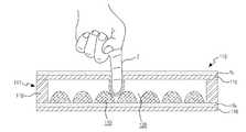
도 1b는 본 발명에 따른 압력을 감지하는 터치패널을 나타내는 단면도이다.
도 1c는 도 1a에 도시되어 있는 터치패널의 다른 일 실시예를 나타내는 개략도이다.
도 2는 도 1a에 도시된 제어부의 일 실시예를 나타내는 블록도이다.
도 3은 도 2에 도시된 터치프로세서의 일 실시예를 나타내는 블록도이다.
도 4a와 도 4b는 본 발명의 실시 예의 터치패널을 스타일러스펜으로 터치했을 때의 터치 영역내의 각각의 감지셀(A,B)의 정전용량 변화량 값을 나타낸 도면이다.
도 5a와 도 5b는 본 발명의 실시 예의 터치패널을 핑거로 터치했을 때의 터치 영역내의 각각의 감지셀(B)의 정전용량 변화량 값을 나타낸 도면이다.
도 6는 본 발명의 실시 예에 따른 터치패널 제어장치의 터치패널 제어 방법의 일 실시예를 도시하는 순서도이다.
도 7은 터치신호의 데이터 형식을 나타낸 개략도이다.
도 8은 도 1a에 도시된 제어부에서 제1터치동작모드와 제2터치동작모드를 처리하는 과정을 나타내는 순서도이다.
도 9a 내지 도 9c는 도 1a에 도시된 제어부에서 선을 표시부에 표시하는 방법에 대한 제1실시예를 나타내는 개념도이다.
도 10a 내지 도 10d는 도 1a에 도시된 제어부에서 선을 표시부에 표시하는 방법에 대한 제2실시예를 나타내는 개념도이다.
도 11은 도 1a에 도시된 제어부에서 선을 표시부에 표시하는 방법에 대한 제3실시예를 나타내는 개념도이다.
도 12는 호버링을 이용하여 지우개의 크기를 선정하는 방법을 나타내는 개념도이다.
도 13은 도 1a에 도시된 터치패널이 터치된 터치형태를 나타내는 개념도이다.
도 14는 본 발명의 실시 예에 따른 터치패널 제어장치를 구비한 전자 장치를 도시한 사시도이다.1A is a block diagram illustrating a touch panel control apparatus according to an embodiment of the present invention.
1B is a cross-sectional view illustrating a touch panel for sensing a pressure according to the present invention.
Fig. 1C is a schematic view showing another embodiment of the touch panel shown in Fig. 1A.
2 is a block diagram showing an embodiment of the control unit shown in FIG.
3 is a block diagram illustrating an embodiment of the touch processor shown in FIG.
FIGS. 4A and 4B are diagrams showing capacitance variation values of the sensing cells A and B in the touch region when the touch panel of the embodiment of the present invention is touched with a stylus pen. FIG.
FIGS. 5A and 5B are diagrams showing capacitance variation values of respective sensing cells B in a touch region when the touch panel of the embodiment of the present invention is touched with a finger. FIG.
6 is a flowchart showing an embodiment of a touch panel control method of a touch panel control apparatus according to an embodiment of the present invention.
7 is a schematic diagram showing the data format of the touch signal.
FIG. 8 is a flowchart illustrating a process of processing a first touch operation mode and a second touch operation mode in the control unit shown in FIG. 1A.
9A to 9C are conceptual diagrams showing a first embodiment of a method of displaying a line on a display unit in the control unit shown in FIG. 1A.
10A to 10D are conceptual diagrams showing a second embodiment of a method of displaying a line on a display unit in the control unit shown in FIG. 1A.
FIG. 11 is a conceptual diagram showing a third embodiment of a method of displaying a line on a display unit in the control unit shown in FIG. 1A.
12 is a conceptual diagram showing a method of selecting the size of the eraser using hovering.
FIG. 13 is a conceptual diagram illustrating a touch mode in which the touch panel shown in FIG. 1A is touched.
FIG. 14 is a perspective view illustrating an electronic device including a touch panel control device according to an embodiment of the present invention.
후술하는 본 발명에 대한 상세한 설명은, 본 발명이 실시될 수 있는 특정 실시 예를 예시로서 도시하는 첨부 도면을 참조한다. 이들 실시 예는 당업자가 본 발명을 실시할 수 있기에 충분하도록 상세히 설명된다. 본 발명의 다양한 실시 예는 서로 다르지만 상호 배타적일 필요는 없음이 이해되어야 한다. 예를 들어, 여기에 기재되어 있는 특정 형상, 구조 및 특성은 일 실시 예에 관련하여 본 발명의 정신 및 범위를 벗어나지 않으면서 다른 실시 예로 구현될 수 있다. 또한, 각각의 개시된 실시 예 내의 개별 구성요소의 위치 또는 배치는 본 발명의 정신 및 범위를 벗어나지 않으면서 변경될 수 있음이 이해되어야 한다. 따라서, 후술하는 상세한 설명은 한정적인 의미로서 취하려는 것이 아니며, 본 발명의 범위는, 적절하게 설명된다면, 그 청구항들이 주장하는 것과 균등한 모든 범위와 더불어 첨부된 청구항에 의해서만 한정된다. 도면에서 유사한 참조부호는 여러 측면에 걸쳐서 동일하거나 유사한 기능을 지칭한다.The following detailed description of the invention refers to the accompanying drawings, which illustrate, by way of illustration, specific embodiments in which the invention may be practiced. These embodiments are described in sufficient detail to enable those skilled in the art to practice the invention. It should be understood that the various embodiments of the present invention are different, but need not be mutually exclusive. For example, certain features, structures, and characteristics described herein may be implemented in other embodiments without departing from the spirit and scope of the invention in connection with one embodiment. It is also to be understood that the position or arrangement of the individual components within each disclosed embodiment may be varied without departing from the spirit and scope of the invention. The following detailed description is, therefore, not to be taken in a limiting sense, and the scope of the present invention is to be limited only by the appended claims, along with the full scope of equivalents to which such claims are entitled, if properly explained. In the drawings, like reference numerals refer to the same or similar functions throughout the several views.
이하, 첨부되는 도면을 참조하여 본 발명의 실시 예를 상세히 설명하도록 한다.Hereinafter, embodiments of the present invention will be described in detail with reference to the accompanying drawings.
도 1a는 본 발명의 실시 예에 따른 터치패널 제어장치를 도시하는 블록도이다.1A is a block diagram illustrating a touch panel control apparatus according to an embodiment of the present invention.
도 1a을 참조하면, 본 발명의 실시예에 따른 터치패널 제어장치(10)는 객체의 터치에 대응하여 적어도 하나의 터치신호를 생성하는 터치패널(110)과, 객체의 터치로 인해 생성되는 선을 표시하는 표시부(130), 터치패널을 터치한 객체에 대응하여 표시부(130)에 객체의 터치 위치의 변화를 선으로 표시하는 제1터치동작모드와 표시부(130)에 표시된 선의 위치에 대응하는 객체의 위치변화에 대응하여 표시부(130)에 표시된 선의 적어도 일부의 제거 및 선의 색좌표변경 중 적어도 하나를 실행하는 제2터치동작모드를 수행하는 제어부(100)를 포함할 수 있다.1A, a touch
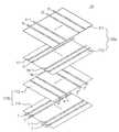
터치패널(110)은 제1방향으로 배열된 복수의 구동 라인들(X1,X2,X3…Xn-1,Xn), 구동 라인들(X1,X2,X3…Xn-1,Xn)과 교차되는 방향으로 배열된 복수의 감지 라인들(Y1,Y2,Y3,…Ym-1,Ym) 및 상기 구동라인들(X1,X2,X3…Xn-1,Xn) 및 감지 라인들(Y1,Y2,Y3,…Ym-1,Ym)의 교차점에 형성되는 복수의 감지셀(A,B)들을 포함하여 구성될 수 있다. 여기서, 복수의 구동라인들(X1,X2,X3…Xn-1,Xn)과 복수의 감지 라인들(Y1,Y2,Y3,…Ym-1,Ym)은 서로 교차하는 것으로 도시되어 있으나 이는 하나의 실시 예로서 그 외에도 다른 기하학적 구성의 교차형태(극좌표 배열의 동심 라인 및 방사상 라인) 등으로 구현될 수도 있다. 또한, 복수의 구동라인들(X1,X2,X3…Xn-1,Xn)과 복수의 감지 라인들(Y1,Y2,Y3,…Ym-1,Ym)은 동일 평면 상에 배치되는 것도 가능할 수 있다.The
복수의 구동 라인들(X1,X2,X3…Xn-1,Xn) 및 복수의 감지 라인들(Y1,Y2,Y3,…Ym-1,Ym)은 투명 기판(미도시) 상에서 투명 도전성 물질로 구현됨이 바람직하다. 이때, 투명 도전성 물질은 ITO(Indium-Tin-Oxide), IZO(Indium-Zinc-Oxide) 또는 CNT(Carbon Nano Tube)로 형성될 수 있다.The plurality of drive lines X1, X2, X3 ... Xn-1, Xn and the plurality of sense lines Y1, Y2, Y3, ... Ym-1, Ym are formed on a transparent substrate Preferably implemented. At this time, the transparent conductive material may be formed of ITO (Indium-Tin-Oxide), IZO (Indium-Zinc-Oxide) or CNT (Carbon Nano Tube).
또한, 복수의 구동 라인들(X1,X2,X3…Xn-1,Xn) 및 감지 라인들(Y1,Y2,Y3,…Ym-1,Ym) 사이에는 유전체로서의 역할을 수행하는 절연층(미도시)이 형성될 수 있다.An insulating layer (not shown) is formed between the plurality of driving lines X1, X2, X3 ... Xn-1, Xn and the sensing lines Y1, Y2, Can be formed.
상기와 같이 구성된 터치패널(110)을 객체가 터치하면, 터치패널(110)의 터치된 부분에 위치하는 복수의 감지셀(A,B)들의 정전용량에 변화가 생김으로써, 터치패널(110)은 정전용량의 변화에 대응하는 터치신호를 생성할 수 있다. 터치패널(110)을 터치하는 객체는 제1객체(1)와 제2객체(2)로 구분할 수 있고, 제1객체(1)는 스타일러스펜일 수 있고, 제2객체(2)는 사용자의 손가락(이하, 핑거)일 수 있다.When the object touches the
일 실시예에 있어서, 터치패널(110)은 복수의 구동라인들(X1,X2,X3…Xn-1,Xn)과 복수의 감지 라인들(Y1,Y2,Y3,…Ym-1,Ym) 사이의 정전용량 변화에 대응하여 터치패널(110)을 제1객체(1) 및/또는 제2객체(2)로 터치한 압력의 크기를 측정할 수 있다. 터치에 의해 가해지는 압력을 검출하는 터치패널(110)의 구조는 하기의 도 1b에 도시되어 있는 것과 같이 구현될 수도 있다.In one embodiment, the
터치패널(110)이 압력의 크기를 감지하는 경우, 제1객체(1)가 터치패널(110)을 터치하는 경우 터치패널(110)에 닿는 면적이 좁고 제2객체(2)가 터치패널(110)을 터치하는 경우 터치패널(110)에 닿는 면적이 제1객체(1)이 닿는 면적보다 더 넓을 수 있다. 따라서, 제1객체(1)가 터치패널(110)에 닿는 면적에 의한 압력분포 변화와 제2객체(1)가 터치패널(110)에 닿는 면적에 의해 발생하는 압력분포변화가 다를 수 있다. 압력분포 변화의 차이가 객체가 제1객체(1)인지 제2객체(2) 인지의 여부를 판단하는데에 사용될 수 있다.When the
일 실시예에 있어서, 터치패널(110)은 도 1c에 도시되어 있는 것과 같이 두 개의 터치패널(110a,110b)을 포함할 수 있으며, 하나의 터치패널(110a)에서 터치의 2차원 위치를 파악하고 나머지 다른 하나의 터치패널(110b)에서 터치 압력의 크기를 파악할 수 있다. 그리고, 두 개의 터치패널(110a,110b)이 동일 평면 상에 겹쳐져 있을 때 하나의 터치패널(110a) 과 다른 하나의 터치패널(110b) 사이에는 절연막(미도시)에 의해 전기적으로 구분될 수도 있다. 그리고, 두 개의 터치패널(110a,110b)이 겹쳐지는 순서 또한 설계자가 임으로 정할 수 있다. 또한, 두 개의 터치 패널(110a,110b)의 크기가 동일한 것으로 도시되어 있지만 이에 한정하는 것은 아니며 두 개의 터치패널의 크기는 서로 다를 수 있다.In one embodiment, the
표시부(130)는 객체의 터치로 인해 생성되는 선이 표시되도록 한다. 여기서, 선은 직선, 곡선, 뿐만 아니라 선들로 이루어진 도형을 의미할 수 있다. 표시부(130)는 터치패널(110)의 하부에 배치될 수 있다. 하지만, 배치되는 위치는 이에 한정되는 것은 아니며 표시부(130) 터치패널(110)과 물리적으로 떨어진 부분에 위치할 수도 있다. 그리고, 표시부(130) 내에 터치패널(130)이 배치될 수도 있다. 표시부(130)는 액정표시장치, 유기발광표시장치일 수 있다.The
제어부(100)는 터치신호에 대응하여 객체가 터치패널(110)에 접촉하는 터치면적에 대응되는 유효터치영역의 정전용량 변화량에 대응하여 터치신호에 제1터치동작모드 또는 제2터치동작모드를 설정하고 각각 독립적으로 수행 수 있다. 또한, 제어부(100)는 제어부(100)는 객체의 터치에 의해 정전용량 변화량에 대응하여 터치패널(110)을 터치한 객체가 가하는 압력을 판단할 수 있고, 객체가 가하는 압력에 대응하는 터치신호에 의해 발생되는 유효터치영역의 정전용량 변화량을 이용하여 터치신호에 제1터치동작모드 또는 제2터치동작모드를 설정하고 각각 독립적으로 수행 수 있다.The
제1터치동작모드는 표시부(130)에 선을 표시할 수 있고, 제2터치동작모드는 표시부(130)에 표시된 선의 적어도 일부를 제거하거나 표시된 선의 색좌표변경을 수행할 수 있다. 제2터치동작모드에 의해 선의 적어도 일부를 제거하게 되면 선의 길이가 짧아지거나 선의 폭이 짧아질 수 있다. 또한, 선 전부가 삭제될 수 있다. 즉, 제2터치동작모드는 지우개 역할을 수행할 수 있다. 또한, 제2터치동작모드에 의해 선의 일부를 삭제하여 폭이 얇아지는 경우 시각적으로 선이 옅어지는 효과가 나타날 수 있다. 그리고, 제2터치동작모드에 의해 선의 색좌표가 낮아지도록 하는 경우도 시각적으로 선이 옅어지는 효과가 나타날 수 있다. 색좌표가 낮아진다는 것은 선의 채도 및/또는 명도가 변경된다는 것을 의미할 수 있다. 유효터치영역은 터치패널(110) 내에서 객체의 터치로 인해 정전용량의 변화 및/또는 압력분포 변화가 발생된 감지셀(A,B)들 중 임의로 정한 범위 내에 속하는 감지셀들로 이루어진 영역을 의미할 수 있다. 감지셀(A,B)의 정전용량 변화 및/또는 압력분포 변화는 유효터치영역의 크기는 객체가 터치패널(100)에 접촉한 면적의 크기의 변화에 대응하여 변할 수 있고 최대로 정전용량이 변화된 감지셀을 중심으로 기설정된 거리내의 감지셀들로 이루어지도록 설정하여 크기가 변하지 않도록 할 수도 있다.The first touch operation mode may display a line on the
제어부(100)는 제1터치동작모드에 의해 표시부(130)에 표시하는 선의 두깨를 객체가 터치패널(110)에 닿는 면적에 대응하여 결정할 수 있다. 또한, 제어부(100)는 제1터치동작모드에 의해 표시부(130)에 표시하는 선의 두깨를 객체가 터치패널(110)에 가하는 압력에 대응하여 결정할 수 있다. 그리고, 제어부(100)는 제2터치동작모드에 의해 표시부(130)에서 지워지는 선의 두께 또는 변경되는 선의 색좌표를 객체가 터치패널(110)에 닿는 면적에 대응하여 결정할 수 있다. 또한, 제어부(100)는 제2터치동작모드에 의해 표시부(130)에서 지워지는 선의 두께 또는 변경되는 선의 색좌표를 객체가 터치패널(110)에 가하는 압력에 대응하여 결정할 수 있다. 객체가 터치패널에 닿는 면적은 유효터치영역의 크기에 대응하여 결정될 수도 있고 기설정된 면적으로 결정될 수도 있다.The
제어부(100)는 터치패널(110)을 터치한 객체가 제1객체(1)인 경우, 제1터치동작모드를 실행하고 터치패널(110)을 터치한 객체가 제2객체(2)인 경우 제2터치동작모드를 실행할 수 있다. 제어부(100)에서 제1터치동작모드 및/또는 제2터치동작모드가 실행되는 경우, 제1객체(1)를 스타일러스펜으로 가정하고 제2객체(2)를 핑거로 가정하면, 제1객체(1)가 터치패널(110)에 접촉하는 면적은 제2객체(2)가 터치패널(110)에 접촉하는 면적보다 더 작을 수 있다. 그리고, 제1객체(1)가 접촉한 복수의 감지셀(A)의 정전용량의 변화는 제2객체(2)가 터치패널(110)에 접촉하여 발생되는 복수의 감지셀(B)의 정전용량의 변화와 다른 분포를 나타낼 수 있다. 또한, 제1객체(1)가 압력을 가한 복수의 감지셀(A)의 압력분포변화와 제2객체(2)가 압력을 가한 복수의 감지셀(B)의 압력분포 변화는 다르게 나타낼 수 있다.The
이러한 차이점을 이용하여 제어부(100)는 제1객체(1)와 제2객체(2)를 구분하여 제1터치동작모드와 제2터치동작모드를 구분하여 실행할 수 있다. 즉, 제어부(100)는 객체가 접촉하여 정전용량의 변화 및/또는 압력분포변화가 발생된 복수의 감지셀들로 이루어진 면적의 크기를 이용하여 터치패널(110)을 터치한 객체의 종류를 구분할 수 있다. 또한, 제어부(100)는 터치패널(110)에 객체가 터치한 부분 중 일부분을 유효터치영역으로 설정하고, 설정된 유효터치영역의 정전용량 변화량 및/또는 압력분포변화량을 이용하여 터치패널(110)을 터치한 객체의 종류를 구분할 수 있다. 제어부(100)에서 객체의 종류를 구분하는 것은 하기의 도 4a, 도 4b, 도 5a, 도 5b에서 보다 자세히 설명한다.Using the difference, the
제어부(100)는 객체에 대응하여 선을 표시하는 제1터치동작모드를 수행할 수 있는데, 여기서, 선은 복수의 점으로 표현되는 선, 그림 등으로 표현될 수 있다. 만약, 객체가 소정 시간 동안 한 지점만 터치하게 되면 제어부(100)는 선을 점으로 표현될 수 있다.The
제어부(100)는 터치패널(110)의 복수의 구동 라인들(X1,X2,X3…Xn-1,Xn)과 복수의 감지 라인들(Y1,Y2,Y3,…Ym-1,Ym)에 각각 구동신호와 감지신호들을 전달할 수 있고, 감지신호를 통해 터치패널을 터치한 2차원좌표를 인식할 수 있다. 또한, 제어부(100)는 터치패널(110)의 복수의 구동 라인들(X1,X2,X3…Xn-1,Xn)과 복수의 감지 라인들(Y1,Y2,Y3,…Ym-1,Ym)에 각각 구동신호와 감지신호들을 전달할 수 있고, 감지신호를 통해 터치패널을 누른 압력을 감지할 수도 있다.The
그리고, 제어부(100)는 압력센서(120)로부터 압력신호를 전달받아 압력신호에 대응하여 제1터치동작모드에서 표시되는 선의 두께 또는 선의 색좌표를 결정하고, 제2터치동작모드에서 선을 지우는 두께 또는 제1터치동작모드에 의해 표시된 선의 색좌표를 변경할 수 있다. 선의 두께가 굵어지면 선의 선명도가 높아 질 수 있고 선의 두께가 얇아지면 선의 선명도가 떨어질 수 있다. 또한, 선의 색좌표에 따라 선의 선명도가 높아질 수도 있고 떨어질 수도 있다. 따라서, 압력신호에 따라 표시되는 선의 두께 및/또는 짙음를 결정할 수 있고 지워져 남는 선의 두께 또는 옅음을 결정할 수 있다. 즉, 제어부(100)는 객체가 터치패널(110)을 누르는 압력에 따라 제1터치동작모드에 의해 표시되는 선의 짙어지는 정도와 제2터치동작모드에 의해 지워져 남는 선의 옅어지는 정도를 결정할 수 있다. 터치패널 제어장치(10)에서 압력센서(120)를 더 포함하게 되면, 제어부(100)는 압력센서에서 출력되는 압력신호를 처리하는 압력감지부(미도시)를 더 포함할 수 있다. 또한, 제어부(100)는 제1객체(1) 및/또는 제2객체(2)에 의해 터치패널(110)에 가해지는 압력이 표시부(130)에 표시되도록 할 수 있다.The
도 1b는 본 발명에 따른 압력을 감지하는 터치패널을 나타내는 단면도이다.1B is a cross-sectional view illustrating a touch panel for sensing a pressure according to the present invention.
도 1b를 참조하면, 터치패널(110)은 터치의 압력의 크기를 보다 효율적으로 검출할 수 있도록 감지 라인(Yk)과 제3절연막(210) 사이를 이격시키는 스페이서층(117: spacer layer)을 포함할 수 있다. 스페이서층(117)은 복수의 도트 스페이서(119: dot spacer)가 포함할 수 있다. 예컨대, 복수의 도트 스페이서(119)는 감지 라인(Yk) 상에 형성될 수 있고, 비전도성 폴리에스테르(nonconductive polyester)와 같은 물질로 구성될 수 있다.Referring to FIG. 1B, the
도 1b에 도시된 바와 같이, 스페이서층(117)은 감지 라인(Yk)과 제3절연막(115)의 각각에 일면이 합착된 양면 접착 테이프(118: DAT: Double Adhesive Tape)를 통해 형성될 수 있다. 즉, 감지 라인(Yk)과 제3절연막(115)은 각각의 면적이 포개어진 형태이고, 이때 감지 라인(Yk)과 제3절연막(115) 각각의 가장자리 영역에서 양면 접착 테이프(118)를 통해서 두 개의 층이 접착되되 나머지 영역에서 감지 라인(Yk)과 제3절연막(115)이 소정 거리로 이격될 수 있다. 제2객체(2)가 터치 패널(110)을 터치할 때, 복수의 구동전극들(Xk) 및 제3절연막(115)은 객체(2)가 가하는 압력에 대응하여 감지 라인들(Yk) 측으로 오목하게 휘어진다. 이때, 구동라인(Xk)과 감지 라인들(Yk) 사이에는 상호 정전 용량을 발생시키도록 서로 단락(short) 되는 것이 방지되어야 한다. 이때, 본 발명의 실시예에서는 제3절연막(115)을 통해 이 둘이 단락되는 현상이 방지될 수 있다.1B, the
이때, 구동라인(Xk)과 감지 라인(Yk) 사이의 상호 정전용량은 구동라인(Xk)과 감지 라인(Yk) 사이의 거리의 변화에 따라 달라질 수 있다. 본 발명의 실시예에서는 구동라인(Xk)과 감지 라인(Yk) 사이의 상호 정전용량의 변화에 따라 외부 압력(600)의 압력의 크기를 감지할 수 있다. 즉, 객체(2)가 가하는 압력이 클수록 구동라인(Xk)과 감지 라인(Yk) 사이의 거리가 짧아지고 이에 따라 상호 정전용량의 변화량이 커질 수 있다. 마찬가지로, 객체(2)가 가하는 압력이 작을수록 구동라인(Xk)과 감지 라인(Yk) 사이의 거리가 줄어드는 폭이 작아지고 이에 따라 정전용량의 변화량이 작을 수 있다. 이때, 객체(2)가 가하는 압력의 크기는 도 1b에서 하측 방향, 즉 수평면에 대해서 수직 및 직교하는 방향의 압력의 크기를 나타낼 수 있다. 도 1b에서 터치패널(110)을 터치하는 객체(2)는 핑거로 도시되어 있으나 이에 한정되는 것은 아니다.At this time, the mutual electrostatic capacitance between the driving line Xk and the sensing line Yk may vary according to the change in the distance between the driving line Xk and the sensing line Yk. In the embodiment of the present invention, the magnitude of the pressure of the external pressure 600 can be sensed according to the change of mutual capacitance between the driving line Xk and the sensing line Yk. That is, the larger the pressure applied by the
도 2는 도 1a에 도시된 제어부의 일 실시예를 나타내는 블록도이다.2 is a block diagram showing an embodiment of the control unit shown in FIG.
도 2를 참조하면, 제어부(100)는 터치프로세서(210) 및 응용프로세서(220)를 포함할 수 있다.Referring to FIG. 2, the
터치프로세서(210)는 터치패널(110)에서 생성된 터치신호를 전달받아 터치패널(110)을 터치한 객체가 제1객체(1) 및 제2객체(2) 중 어느 하나인지를 파악할 수 있다. 제1객체(1)가 스타일러스펜이고 제2객체(2)가 핑거이면, 제1객체(1)가 터치패널(110)에 접촉하여 정전용량의 변화가 발생된 감지셀(A)들로 이루어진 터치면적이 제2객체(2)가 터치패널(110)에 접촉하여 정전용량의 변화가 발생된 감지셀(B)들로 이루어진 터치면적보다 더 작을 수 있다. 이러한 터치면적의 크기 차이를 이용하여, 터치프로세서(210)는 터치패널(110)에 제1객체(1) 및/또는 제2객체(2)의 접촉여부를 구별할 수 있다. 또한, 터치패널(110)에 객체가 터치한 부분 중 적어도 일부분을 유효터치영역으로 설정하고, 터치프로세서(210)는 설정된 유효터치영역의 정전용량 변화량을 이용하여 터치패널(110)을 터치한 객체가 제1객체(1) 및/또는 제2객체(2) 여부 인지를 구별할 수 있다. 유효터치 영역의 정전용량 변화량은 객체에 따라 터치패널(110)에 가하는 압력에 의해 달라질 수 있다.The
또한, 터치프로세서(210)는 터치패널(110)을 터치한 객체가 제1객체(1)인 경우 터치신호에 제1터치동작모드를 설정하고 터치패널(110)을 터치한 객체가 제2객체(2)인 경우 터치신호에 제2터치동작모드를 설정할 수 있다. 제1터치동작모드는 터치프로세서(210)에서 선을 표시하도록 하는 모드이고, 제2터치동작모드는 터치프로세서(210)에서 선을 지우도록 하는 모드일 수 있다. 터치프로세서(210)는 객체에 대응하여 터치신호에 각각 제1터치동작모드 및/또는 제2터치동작모드를 설정하는 방법으로, 터치신호에 각각 다른 플래그를 부여할 수 있다. 즉, 터치프로세서(210)는 구별된 객체에 대응한 두 개 이상의 터치신호에 각각 독립적으로 플래그를 부여할 수 있다. 제1객체(1)에 의해 발생된 터치신호에 부여되는 플래그를 제1터치동작모드플래그라고 칭하고 제2객체(2)에 의해 발생된 터치신호에 부여되는 플래그를 제2터치동작모드플래그라고 칭할 수 있다.If the object touching the
또한, 터치프로세서(210)는 플래그가 부여된 터치신호들 중에서 인덱스 매칭 조건을 만족하는 터치신호에는 동일한 인덱스를 부여하고, 인덱스 매칭 조건을 만족하지 않는 터치신호에는 다른 인덱스를 부여한다. 이로 인해, 터치프로세서(210)는 부여된 인덱스를 이용함으로써, 터치패널(110)을 터치한 복수의 터치들을 검출하여 단일 터치와 이중 터치를 구별할 수 있다. 즉, 하나의 터치와 다른 터치가 동일한 인덱스를 부여받은 경우 터치프로세서(210)는 단일터치로 인식하여 제1터치동작모드이면 하나의 터치와 다른 터치가 발생된 지점을 하나의 선으로 표시할 수 있고 제2터치동작모드이면 하나의 터치와 다른 터치가 이루어진 지점 사이의 선을 지울 수 있도록 할 수 있다. 여기서, 인덱스 매칭 조건은 예컨대, 터치 입력 시간 차이 및/또는 터치 간의 거리 등을 이용하여 만들 수 있다.Also, the
또한, 터치프로세서(210)은 압력센서(120)로부터 압력신호를 전달받아 압력에 따라 터치신호에 압력정보를 부가하여 제1터치동작모드에서 표시되는 선이 압력정보에 의해 선의 두께 및/또는 색좌표가 결정될 수 있도록 할 수 있다. 또한, 제2터치동작모드에서 지워져 남는 선의 두께 및/또는 색좌표가 결정될 수 있도록 할 수 있다. 선의 두께는 선의 폭에 의해 결정될 수도 있고 선의 짙음과 옅음에 의해 결정될 수도 있다.In addition, the
응용프로세서(220)는 터치프로세서(210)로부터 전달받은 제1터치동작모드와 제2터치동작모드에 대응하는 표시신호를 표시부(130)에 전달할 수 있다. 표시부(130)는 표시신호에 의해 선을 표시하거나 선을 지울 수 있다. 즉, 응용프로세서(220)는 터치프로세서(210)에 의해 제1터치동작모드가 설정된 터치신호에 의해 객체의 터치위치의 변화에 대응하는 선을 표시하는 제1터치동작모드를 수행하여 표시부(130)에 선을 표시할 수 있다. 응용프로세서(220)는 제1터치동작모드를 통해 표시하는 선은 복수의 점으로 구성되는 선, 그림 등으로 표현될 수 있으며, 만약, 객체가 소정 시간 동안 한 지점만 터치하게 되면 제1터치동작모드는 선을 점으로 표현될 수 있다. 또한, 응용프로세서(220)는 제2터치동작모드가 설정된 터치신호에 의해 객체의 터치위치 변화에 대응하여 표시부(130)에 표시된 선 등을 지우는 제2터치동작모드를 수행하여 표시부(130)에 표시된 선의 적어도 일부를 지울 수 있다. 응용프로세서(220)는 터치프로세서(210)에서 터치신호에 부여한 플래그를 이용하여 제1터치동작모드를 수행할 터치신호와 제2터치동작모드를 수행할 터치신호를 구별하여 수행할 수 있다. 또한, 응용프로세서(220)는 터치프로세서(210)에서 터치신호에 부여한 인덱스를 이용하여 단일 터치와 이중 터치를 구별하여 선이 표시되거나 지워질 수 있도록 할 수 있다.The
도 3은 도 2에 도시된 터치프로세서의 일실시예를 나타내는 블록도이다.3 is a block diagram illustrating an embodiment of the touch processor shown in FIG.
도 3을 참조하면, 터치프로세서(210)는 터치제어부(310), 구동부(320), 터치신호감지부(330)를 포함할 수 있다.Referring to FIG. 3, the
터치제어부(310)는 구동부(320), 터치신호감지부(330) 등을 제어하고 터치패널(130)을 터치한 터치 동작에 대응하여 발생된 터치 신호를 이용하여 제1터치동작모드 또는 제2터치동작모드를 각각 독립적으로 설정할 수 있다.The
구동부(320)는 터치패널(110)의 복수의 구동 라인들(X1,X2,X3…Xn-1,Xn)과 연결되고 터치신호감지부(330)는 복수의 감지 라인들(Y1,Y2,Y3,…Ym-1,Ym)과 연결되어 각각 구동신호과 감지신호들을 전달할 수 있다. 구동부(320)는 터치제어부(100)의 제어에 의해 복수의 구동 라인들(X1,X2,X3…Xn-1,Xn)에 순차적으로 구동신호를 인가할 수 있다. 터치신호감지부(330)는, 터치제어부(100)의 제어에 의해 감지 라인들(Y1,Y2,Y3…Ym-1,Ym)로 감지신호를 전달하여 각 감지셀(A,B)들로부터 감지된 정전용량 변화에 대응한 터치신호를 전달받을 수 있다. 터치신호감지부(330)는 터치신호를 호버, 노이즈 등과 같은 터치 오류로부터 명확히 구별하기 위해서, 터치패널(110)으로부터 입력된 신호를 미리 설정된 임계치에 의해 분석할 수 있다.The driving
일 실시예에 있어서, 터치프로세서(210)는 메모리부(340)를 더 포함할 수 있다. 또한, 메모리부(340)는 터치제어부(310)에 연결될 수도 있다. 메모리부(340)는 터치프로세서(210)를 구동하는 프로그램이 저장될 수 있고, 플래그 및/또는 인덱스가 저장될 수 있다. 또한, 펌웨어 등이 저장될 수도 있다. 또한, 메모리부(340)에는 적어도 제1터치동작모드, 제2터치동작모드를 구분하기 위한 객체의 유효터치영역의 면적정보가 저장될 수 있다. 유효터치영역의 면적정보는 터치로 인해 정전용량의 변화가 발생되는 감지셀의 수 일 수 있다. 또한, 면적정보는 유효터치영역의 크기와 유효터치 영역 내의 복수의 감지셀들의 정전용량 변화의 형태 등일 수 있다. 또한, 메모리부(340)에는 복수의 유효터치영역의 형태에 대한 형태정보를 저장할 수 있다. 터치프로세서(210)는 메모리부(340)에 저장되어 있는 형태정보를 이용하여 유효터치여부를 파악할 수 있다. 형태 정보는 복수의 유효터치들로 이루어진 형태를 이용하여 유효터치의 형태가 사용자의 손바닥과 같은 형태이면 그 유효터치의 형태에 포함된 터치는 유효한 터치로 인식하지 않도록 할 수 있다. 여기서, 메모리부(340)은 터치프로세서(210) 내에 포함되어 있는 것으로 도시되어 있으나 이에 한정되는 것은 아니며, 응용프로세서(220) 내에 포함되는 것도 가능하다. 즉, 제어부(100)의 내에 위치할 수 있다.In one embodiment, the
일 실시예에 있어서, 터치프로세서(210)는 압력신호감지부(350)를 더 포함할 수 있다. 압력신호감지부(350)는 압력센서(120)로부터 압력신호를 전달받아 압력신호에 대응하여 제1터치동작모드에 의해 표시되는 선의 두께 및/또는 선의 색좌표를 결정할 수 있다. 또한, 압력신호감지부(350)는 압력센서(120)로부터 압력신호를 전달받아 압력신호에 대응하여 제2터치동작모드에 의해 지워지는 선의 두께 및/또는 남는 선의 색좌표를 결정할 수 있다. 또한, 압력신호감지부(350)는 표시부(130)에 객체가 터치패널을 누르는 압력이 표시될 수 있도록 할 수 있다. 또한, 메모리부(340)에는 압력센서(120)에서 발생된 압력신호에 대응하는 선의 두께 및/또는 선의 색좌표 정보를 더 포함할 수 있다.In one embodiment, the
도 4a와 도 4b는 본 발명의 실시 예의 터치패널을 스타일러스펜으로 터치했을 때의 터치 영역내의 각각의 감지셀(A,B)의 정전용량 변화량 값을 나타낸 도면이다. 또한, 도 5a와 도 5b는 본 발명의 실시 예의 터치패널을 핑거로 터치했을 때의 터치 영역내의 각각의 감지셀(B)의 정전용량 변화량 값을 나타낸 도면이다.FIGS. 4A and 4B are diagrams showing capacitance variation values of the sensing cells A and B in the touch region when the touch panel of the embodiment of the present invention is touched with a stylus pen. FIG. 5A and 5B are diagrams showing capacitance variation values of respective sensing cells B in a touch region when the touch panel of the embodiment of the present invention is touched with a finger.
여기서, 도 4a와 도 5a는 각각 터치영역 내 최대 정전용량 변화량을 갖는 감지셀이 하나인 경우를 나타낸 도면이고, 도 4b와 도 5b는 각각 상기 터치영역 내 최대 정전용량 변화량을 갖는 감지셀이 하나 이상인 경우를 나타낸 도면이다. FIGS. 4A and 5A are diagrams illustrating a case where one sense cell having a maximum capacitance change amount in the touch region is one, FIG. 4B and FIG. 5B are diagrams illustrating a case where one sense cell having the maximum capacitance change amount in the touch region is one Or more.
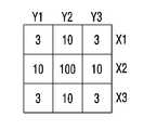
그리고 하기 표 1은 제어부(100)에서 객체의 종류를 구분하기 위한 설명을 나타내는 표이다.Table 1 below shows a table for identifying the types of objects in the
도 4a와 도 4b 및 도 5a와 도 5b의 도면과 표 1을 참조하여 설명한다.Will be described with reference to Figs. 4A and 4B and Figs. 5A and 5B and Table 1.
제어부(100)는 정전용량 변화량의 합을 비교하여 터치한 객체의 종류를 구분할 수 있고, 터치 영역 내에서 소정의 정전용량 변화량을 넘는 감지셀(A,B)의 개수를 비교하여 터치한 객체의 종류를 구분할 수 있고, 터치 영역 내에서 최대 정전용량 변화량 또는 최소 정전용량 변화량의 소정 비율을 넘는 감지셀(A,B)의 수를 비교하여 터치한 객체의 종류를 구분할 수 있다. 또한, 터치 영역 내의 정전용량 변화량 상위 및 하위 소정 개수의 정전용량 변화량의 합의 비율을 비교하여 터치한 객체를 구분할 수 있다.The
먼저, 제어부(100)가 상기 터치 영역내의 각각의 감지셀(A,B)의 정전용량 변화량의 합을 비교하여 객체의 종류를 구분하는 방법을 설명한다. 제어부(100)는 터치 영역내의 감지셀(A,B)의 정전용량 변화량의 합을 파악하고, 정전용량 변화량의 합이 임계치보다 작은 값인 경우에 터치한 객체의 종류는 제1객체(1)인 스타일러스펜으로 판정하고 임계치보다 큰 경우 터치한 객체의 종류른 제2객체(2)인 핑거로 판정할 수 있다. 임계치는 180으로 가정할 수 있다. 예컨대, 도 4a에 도시된 바와 같이, 152(100+10+10+10+10+3+3+3+3)이거나 도 4b에 도시된 바와 같이, 141(50+50+8+8+8+8+5+2+2)인 경우이면 제1객체(1)가 터치한 것으로 도 5a에 도시된 바와 같이, 260(100+30+30+30+30+10+10+10+10)이거나 도 5b에 도시된 바와 같이, 226(50+50+25+25+25+25+10+8+8)인 경우이면 제2객체(2)가 터치한 것으로 판정할 수 있다.First, a description will be given of a method for the
그리고, 제어부(100)가 터치 영역 내에서 소정의 정전용량 변화량을 넘는 감지셀(A,B)의 개수를 비교하여 객체의 종류를 구분하는 방법을 설명한다. 제어부(100)는 소정의 정전용량 변화량을 20으로 정하고 20보다 큰 변화량을 갖는 감지셀 수의 임계치를 3개로 가정할 수 있다. 제어부(100)는 터치 영역 내에서 20보다 큰 정전용량변화량을 갖는 감지셀(A,B)의 개수가, 3개 보다 작은 경우에, 제어부(100)는 터치된 객체를 제1객체(1)인 스타일러스펜으로 판정할 수 있고 터치 영역 내에서 20보다 큰 정전용량변화량을 갖는 감지셀(B)의 개수가, 3개 보다 큰 경우에 핑거로 판정할 수 있다. 예컨대, 제어부(100)는 20보다 큰 정전용량변화량을 갖는 감지셀(A,B)의 개수가 임계치인 3개 보다 작은 도 4a에 도시된 바와 같이 1개(100)이거나 도 4b에 도시된 바와 같이, 2개(50,50)인 경우이면 제1객체(1)가 터치한 것으로, 터치 영역 내에서 20보다 큰 정전용량 변화량을 갖는 감지셀(A,B)의 개수가, 임계치인 3개 보다 보다 큰 도 5a에 도시된 바와 같이, 5개(30,30,30,30,100)이거나 도 5b에 도시된 바와 같이, 6개(25,25,25,25,50,50)인 경우이면 제2객체(2)가 터치한 것으로 판단할 수 있다.A method of dividing the types of objects by comparing the number of the sensing cells A and B exceeding a predetermined capacitance change amount in the touch region by the
또한, 제어부(100)가 터치 영역 내에서 최대 정전용량 변화량 또는 최소 정전용량 변화량의 소정 비율을 넘는 감지셀(A,B)의 수를 비교하여 객체의 종류를 구분하는 방법을 설명한다. 제어부(100)는 소정비율을 25%로 정하고 터치 영역 내에서 최대 정전용량 변화량의 25%를 넘는 정전용량변화량을 갖는 감지셀(A,B)의 수의 임계치를 3개로 가정할 수 있다. 제어부(100)는 터치 영역 내에서 임계치보다 작은 경우에 제1객체(1)인 스타일러스펜으로 판정할 수 있고 임계치보다 큰 경우에 제2객체(2)인 핑거로 판정할 수 있다. 예컨대, 도 4a에 도시된 바와 같이, 0개이거나 도 4b에 도시된 바와 같이, 1개(50)인 경우이면, 제1객체(1)가 터치한 것으로, 터치 영역 내에서 최대 정전용량 변화량의 25%를 넘는 정전용량 변화량을 갖는 감지셀(A,B)의 개수가, 도 5a에 도시된 바와 같이, 4개이거나 도 5b에 도시된 바와 같이, 5개인 경우이다.A method of dividing the types of objects by comparing the number of sensing cells A and B in the touch region with the maximum capacitance change amount or the minimum capacitance change amount is described below. The
또한, 제어부(100)가 터치 영역 내의 정전용량 변화량 상위 및 하위 소정 개수의 정전용량 변화량의 합의 비율을 비교하여 객체의 종류를 구분하는 방법을 설명한다. 제어부(100)는 소정 개수가 4개로 정해진 경우에 터치 영역 내의 정전용량 변화량 상위 4개의 정전용량 변화량의 합과 터치 영역 내의 정전용량 변화량 하위 4개의 정전용량 변화량의 합의 비율이, 6인 임계치보다 큰 경우에 터치된 객체는 제1객체(1)인 스타일러스펜으로 판정할 수 있고 임계치보다 작은 경우에 터치된 객체는 제2객체(2)인 핑거로 판정할 수 있다. 예컨대, 도 4a에 도시된 바와 같이, 10.8(130÷12)이거나 도 4b에 도시된 바와 같이, 6.8(116÷17)인 경우이면 제1객체(1)로 판정하고, 도 5a에 도시된 바와 같이, 4.75(190÷40)이거나 도 5b에 도시된 바와 같이, 2.9(150÷51)인 경우이면 제2객체(2)로 판정할 수 있다.A method of dividing the types of objects by comparing the ratios of the sum of the upper and lower predetermined capacitance change amounts in the touch region by the
상기 각 방법들의 임계치는 객체를 구별할 수 있도록 조정될 수 있다. 또한, 도 4a 내지 도 5b에서 유효터치영역의 크기가 3 의 크기를 갖는 것으로 도시되어 있으나 이는 예시적인 것이며 유효터치영역의 크기는 3 보다 더 큰 크기를 가질 수도 있고 터치패널(110)을 터치하는 객체의 종류에 따라 유효터치영역의 크기가 다르게 설정될 수도 있다. 또한, 객체가 터치패널(110)에 접촉하는 면적에 따라 다르게 설정될 수도 있다. 터치패널(110)에 접촉하는 면적은 정전용량변화량의 차이를 이용하여 구별할 수 있다.The threshold of each of the above methods may be adjusted to distinguish the objects. 4A and FIG. 5B, the size of the effective touch area is shown to have a size of 3, but this is an exemplary one, and the size of the effective touch area may have a size larger than 3, The size of the effective touch area may be set differently depending on the object type. In addition, the object may be set differently depending on the area in which the object contacts the
도 6는 본 발명의 실시 예에 따른 터치패널 제어장치의 터치패널 제어 방법의 일 실시예를 도시하는 순서도이다. 본 발명의 실시 예에 따른 터치패널 제어장치의 터치패널 제어 방법은 제어부(100)의 동작에 의해 실행될 수 있다.6 is a flowchart showing an embodiment of a touch panel control method of a touch panel control apparatus according to an embodiment of the present invention. The touch panel control method of the touch panel control apparatus according to the embodiment of the present invention can be executed by the operation of the
도 6에 도시된 바와 같이, 터치패널(110)을 제어하는 방법은 터치패널(110)에 터치신호의 입력이 발생하였는지를 스캔한다.(S600) 스캔은 복수의 구동라인과 복수의 감지라인을 통해 형성된 감지셀(A,B)의 상호 정전용량 변화를 감지하고 감지된 변화량과 임계치 등을 이용하여 호버링, 노이즈 등과 터치 입력을 구별할 수 있다. 스캔을 통해 터치 신호가 입력된 것으로 판단되면, 입력된 터치신호가 제1터치동작모드 입력조건 해당하는지의 여부를 판단한다.(S610) 그리고, 터치신호를 분석하여 터치신호에 제1터치동작모드 플래그 또는 제2터치동작모드 플래그를 부여 한다.(S620) 즉, 터치신호가 제1터치동작모드 입력조건에 해당하면 터치신호에 제1터치동작모드 플래그를 부여하고, 터치신호가 제1터치동작모드 입력조건에 해당하지 않으면 제2터치동작모드 플래그를 부여한다. 부여된 플래그에 대응하여 터치신호를 제1터치동작모드 또는 제2터치 동작모드로 설정될 수 있다.6, the method of controlling the
그리고, 제1터치동작모드와 제2터치 동작모드는 각각 동일한 플래그가 부여된 터치신호 중 연속된 터치신호에 동일한 인덱스를 부여하고(S630), 인덱스에 따라 터치패널(110)에 입력된 복수의 터치들을 하나의 연속된 입력 또는 별개의 입력으로 구별할 수 있다.(S640) 즉, 동일한 인덱스가 부여된 복수의 터치 입력은 단일 터치로 인식하고 서로 이어져 있는 것으로 표시되게 할 수 있다.In the first touch operation mode and the second touch operation mode, the same index is given to the continuous touch signals among the touch signals having the same flag, respectively (S630), and a plurality of It is possible to distinguish the touches as one continuous input or a separate input (S640). That is, a plurality of touch inputs having the same index can be recognized as a single touch and displayed as being connected to each other.
또한, 플래그와 인덱스에 따라 터치신호를 처리하여 제1터치동작모드를 수행하여 선을 표시하거나, 제2터치동작모드를 수행하여 제1터치동작모드에서 표시된 선의 적어도 일부를 제거하거나 선의 색좌표를 변경할 수 있다.(S650)In addition, a touch signal may be processed according to a flag and an index to perform a first touch operation mode to display a line, or a second touch operation mode to remove at least a part of a line displayed in the first touch operation mode, (S650)
본 실시예에 있어서, 플래그를 부여하는 동작과 관련된 프로세스(S610 내지 S620)과 인덱스를 부여하는 동작과 관련된 프로세스(S630)는 순차적으로 설명하였지만, 프로세스의 전후 관계가 상술한 것과 반대의 경우도 있을 수 있다. 따라서, 본 발명의 개념은 플래그를 부여하는 동작과 관련된 프로세스(S610 내지 S620)과 인덱스를 부여하는 동작과 관련된 프로세스(S630)의 전후 관계에 직접적으로 제한되는 것은 아니다.In the present embodiment, the process (S610 to S620) related to the operation of assigning flags and the process (S630) related to the operation of assigning indexes have been described in sequence, but there are cases where the context relationship of the process is opposite to that described above . Therefore, the concept of the present invention is not limited directly to the context of the process (S610 to S620) related to the operation of assigning flags and the process (S630) related to the operation of assigning indexes.
따라서, 이러한 터치된 객체에 따른 정전용량 변화량의 특징을 이용하여 상기 터치 영역내의 각각의 감지셀(A,B)의 정전용량 변화량의 합, 터치 영역 내에서 소정의 정전용량 변화량을 넘는 감지셀(A,B)의 개수, 터치 영역 내에서 최대 정전용량 변화량 또는 최소 정전용량 변화량의 소정 비율을 넘는 감지셀(A,B)의 개수, 터치 영역 내의 정전용량 변화량 상위 및 하위 소정 개수의 정전용량 변화량의 합의 비율 등과 같은 하나 이상의 터치신호 파라미터를 비교함으로써 유효터치가 어떠한 객체의 터치 입력조건들을 만족하는지를 판단할 수 있다.Therefore, by using the feature of the capacitance variation according to the touched object, the sum of the capacitance change amounts of the sensing cells A and B in the touch area, and the sum of the capacitance variation amounts of the sensing cells (A and B) The number of sensing cells A and B exceeding a predetermined ratio of the maximum capacitance change amount or the minimum capacitance change amount in the touch region, the capacitance change amount of the upper and lower predetermined number of capacitance change amounts in the touch region, Such as the ratio of the number of touches to the number of touches, the ratio of the sum of the touches, and the like.
도 7은 터치신호의 데이터 형식을 나타낸 개략도이다.7 is a schematic diagram showing the data format of the touch signal.
도 7을 참조하면, 플래그가 부여된 터치 신호의 데이터 형식은 플래그, 좌표값의 필드를 가질 수 있다. 또한, 인덱스가 부여된 터치 신호의 데이터 형식은 플래그, 인덱스, 좌표값의 필드를 가질 수 있다. 또한, 압력정보가 부여된 터치신호의 데이터형식은 플래그, 인덱스, 압력정보, 좌표값의 필드를 가질 수 있다.Referring to FIG. 7, the data format of the flagged touch signal may have a field of a flag and a coordinate value. The data format of the touch signal to which the index is assigned may have fields of flags, indexes, and coordinate values. The data format of the touch signal to which the pressure information is given may have fields of flags, indices, pressure information, and coordinate values.
도 8은 도 1a에 도시된 제어부에서 제1터치동작모드와 제2터치동작모드를 처리하는 과정을 나타내는 순서도이다.FIG. 8 is a flowchart illustrating a process of processing a first touch operation mode and a second touch operation mode in the control unit shown in FIG. 1A.
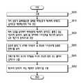
도 8을 참조하면, 제어부(100)는 제1터치동작모드와 제2터치동작모드를 처리하기 위한 방법은 복수의 터치신호들 중 선을 표시하는 제1터치동작모드가 설정된 터치신호들을 이용하여 적어도 하나의 선을 표시할 수 있다.(S801)Referring to FIG. 8, the method for processing the first touch operation mode and the second touch operation mode may be performed by using the touch signals set in the first touch operation mode indicating a line among the plurality of touch signals At least one line can be displayed (S801)
일 실시예에 있어서, 제어부(100)는 선을 표시하는 동작을 수행할 때, 제1터치동작모드에 의해 표시된 선이 교차되는 경우 교차된 지점의 선의 두께 또는 선의 색좌표는 교차되지 않은 지점보다 더 굵게 표시될 수 있도록 할 수 있다. 즉, 제어부(100)는 표시부(130)에 표시된 선의 좌표값을 저장하고 저장된 선의 좌표값 중 적어도 일부의 좌표값이 동일한 좌표값을 갖는 선에 대한 터치 신호가 입력되면, 동일한 좌표값을 갖는 부분은 서로 다른 선이 교차된 것으로 판단할 수 있다. 그리고, 제어부(100)는 교차된 지점의 두께를 교차되지 않은 부분 보다 더 두껍게 하도록 할 수 있다. 표시부(130)에 표시된 선의 좌표값은 메모리부(340)에 저장될 수 있다.In one embodiment, when performing a line display operation, when the line indicated by the first touch operation mode is crossed, the thickness of the line at the intersected point or the color coordinate of the line is longer than the non- It can be displayed in bold. That is, the
그리고, 제어부(100)는 복수의 터치신호들 중 제1터치동작모드에 의해 표시된 선을 제거하거나 상기 표시된 선의 색좌표를 변경하는 제2터치동작모드가 설정된 터치신호들을 이용하여 제2터치동작모드를 수행하여 상기 제1터치동작모드에 의해 표시된 선 중 적어도 일부를 제거 또는 상기 선의 색좌표를 변경 중 적어도 하나를 수행할 수 있다.(S802)Then, the
일 실시예에 있어서, 상기 제2터치동작모드가 수행되는 과정에서 제1터치동작모드에 의해 표시된 복수의 선들을 표시된 역순으로 제거할 수 있다. 이를 위해, 제어부(100)는 복수의 선들의 생성순서에 대한 순서정보를 저장하고 제어부(100)는 순서정보를 이용하여 표시된 복수의 선들을 역순으로 제거할 수 있다.In one embodiment, in the course of performing the second touch operation mode, a plurality of lines displayed by the first touch operation mode may be removed in the reverse order of display. For this, the
일 실시예에 있어서, 제2터치동작모드 수행 후 선의 적어도 일부가 제거된 부분의 시작점과 끝점이 표시될 수 있다.(S803) 제어부(100)는 제2터치동작모드 수행 후 선의 적어도 일부가 제거된 부분의 좌표값을 저장하고 제거된 선의 시작점과 끝점에 대응되는 좌표값을 이용하여 시작점과 끝점이 표시될 수 있도록 할 수 있다.In one embodiment, the start point and the end point of a portion where at least a portion of the line is removed after the second touch operation mode is performed may be displayed. (S803) After performing the second touch operation mode, And the start point and the end point can be displayed by using coordinate values corresponding to the start and end points of the removed line.
일 실시예에 있어서, 시작점과 끝점을 잇는 가상의 직선이 터치되도록 하는 단계와(S804), 가상의 직선이 터치되면 제2터치동작모드에서 제거된 상기 선이 다시 표시되도록 하는 단계를 더 포함할 수 있다.(S805) 제어부(100)는 제거된 선의 시작점과 끝점을 잇는 터치가 발생하게 되면, 저장되어 있는 제거된 선의 좌표값 정보를 이용하여 제거된 선을 다시 표시할 수 있도록 할 수 있다.In one embodiment, the method may further include a step of causing a virtual straight line connecting the start point and the end point to be touched (S804), and causing the line removed in the second touch operation mode to be displayed again when a virtual straight line is touched (S805) When a touch connecting the start point and the end point of the removed line occurs, the
상기의 과정을 제2터치동작모드에서 선의 색좌표가 변경된 부분에도 적용하여 제어부(100)는 색좌표가 변경된 부분의 좌표값 정보를 저장하고 좌표값을 이용하여 색좌표가 변경된 선의 시작점과 끝점이 표시되도록 할 수 있다. 또한, 제어부(100)는 색좌표가 변경된 선의 좌표값을 저장하고 좌표값 정보를 이용하여 색좌표가 변경된 선의 시작점과 끝점을 잇는 터치가 발생하게 되면, 색좌표가 변경된 선의 색좌표를 다시 복원할 수 있다.The
일 실시예에 있어서, 제1터치동작모드와 제2터치동작모드는 제어부(100)의 터치프로세서(210)에서 처리되어 표시부(130)에 표시되도록 할 수 있다.In one embodiment, the first touch operation mode and the second touch operation mode may be processed by the
도 9a 내지 도 9c는 도 1a에 도시된 터치처리부에서 선을 표시부에 표시하는 방법에 대한 제1실시예를 나타내는 개념도이다.Figs. 9A to 9C are conceptual diagrams showing a first embodiment of a method of displaying a line on a display unit in the touch processing unit shown in Fig. 1A.
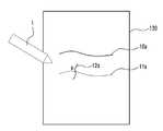
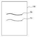
도 9a 내지 도 9c를 참조하면, 제어부(100)는 표시부(130)에서 도 9a에 도시되어 있는 것과 같이 제1터치동작모드에 의해 일정한 선(10a,11a,12a)을 표시할 수 있도록 할 수 있다. 제어부(100)에서 표시부(130)에 표시하는 선의 두께는 조절될 수 있다. 선의 두께는 터치패널(110)에 가해지는 압력을 감지하여 결정할 수 있다. 즉, 객체가 터치패널(110)에 가하는 압력이 높으면 선(10a)와 같이 굵게 표시되고 압력이 낮으면 선(11a)와 같이 얇게 표시될 수 있다. 그리고, 선(11a) 및 선(12a)과 같이 표시부(130)에 표시되는 선들이 교차할 수 있다. 선(11a,12a)이 교차하는 경우 교차점(P1)은 교차하지 않은 부분보다 더 굵게 표시할 수 있다. 또한, 교차점(P1)의 두께는 하나의 선(11a)와 그 선과 교차하는 다른 선(12a)의 두께의 합으로 결정될 수 있다. 즉, 선(11a)이 그려질 때 터치패널에 가해지는 압력과 선(12a)이 그려질 때 터치패널에 가해지는 압력의 합을 이용하여 교차점(P1)의 두께의 합을 결정할 수 있다. 그리고, 제어부(100)는 도 9b에 도시되어 있는 것과 같이 제2터치동작모드에 의해 선 폭(w1)의 변화없이 일부를 제거하여 선(10b)의 길이가 짧아지도록 할 수 있도록 할 수 있다.(지워진 부분은 점선으로 표시함) 또한, 선의 일부를 제거하여 선(11b)와 같이 폭이 얇아지도록 하는 것도 가능하다. 선(11b)의 폭이 얇아지도록 하는 것은 선(11b)가 너무 두껍게 그려진 경우 제2객체(2)인 핑거를 이용하여 선을 지울 때 터치패널에 가해지는 압력을 감지하여 압력이 높으면 약하게 가하면 선(11b)의 두께를 제1두께(w2)에서 제2두께(w3)로 얇아지게 할 수 있다. 선이 얇아지면 시각적으로 선이 흐릿하게 보일 수도 있다. 또한, 도 9c에 도시되어 있는 것과 같이 제2터치동작모드에 의해 선이 옅게 표시되도록 할 수 있다. 제2터치동작모드는 선을 제거하는데, 터치하는 객체의 압력을 감지하여 압력이 높으면 표시부(130)에 표시된 선을 전부 제거할 수 있다. 하지만, 제2터치동작모드가 수행되도록 하는 객체가 터치패널(110)에 가하는 압력이 낮으면 표시부(130)에 표시된 선을 옅게 할 수 있다. 즉, 제1터치동작모드에서 표시된 표시부(130)의 상부에 표시된 선(10c)을 옅게 하면 표시부(130)의 하부에 표시된 선(11c)과 같이 색이 옅어질 수 있다. 터치패널(110)에 가해지는 객체의 압력이 낮은 것은 제1터치동작모드가 수행될 때 터치패널(110)에 가해지는 압력보다 제2터치동작모드가 수행될 때 터치패널(110)에 가해지는 압력이 낮은 것을 의미할 수 있다. 선이 옅어지는 것은 선의 색좌표를 조절하는 것으로 가능할 수 있다.9A to 9C, the
또한, 제어부(100)는 제2터치동작모드를 수행할 때, 제2객체로 복수의 선들이 교차된 지점을 일정시간 동안 터치를 하면 제1터치동작모드에 의해 표시된 복수의 선들을 표시된 역순으로 제거할 수 있다. 따라서, 특정한 위치를 터치를 하지 않더라도 손쉽게 표시된 선들을 제거할 수 있다.In addition, when performing the second touch operation mode, the
도 10a 내지 도 10d는 도 1a에 도시된 터치처리부에서 선을 표시부에 표시하는 방법에 대한 제2실시예를 나타내는 개념도이다.Figs. 10A to 10D are conceptual diagrams showing a second embodiment of a method of displaying a line on a display unit in the touch processing unit shown in Fig. 1A.
제어부(100)는 도 10a 및 도 10b에 도시되어 있는 것과 같이 압력센서(120)의 압력신호에 대응되는 터치신호의 압력정보 필드를 이용하여 표시부(130)의 일측에 압력게이지(21)가 나타나도록 할 수 있다. 일 실시예에 있어서, 제어부(100)에 포함되어 있는 응용프로세서(220)에서 표시부(130)의 일측에 압력게이지(21)가 나타나도록 할 수 있다. 압력게이지(21)를 이용하여 사용자는 객체가 터치패널에 가하는 압력을 알 수 있다. 압력게이지(21)는 눈금으로 표시되어 있으나 이에 한정되는 것은 아니며 바 타입으로 표시되고 바의 길이에 대응하여 압력이 표시되도록 하는 것도 가능하다. 또한, 제어부(100)는 도 10c 및 도 10c에 도시되어 있는 것과 같이 표시부(130)의 일측에 압력게이지(21)가 아닌 압력신호에 대응되는 표시될 선의 두께 또는 지워질 선을 지우는 지우개의 크기가 표시되는 창(22,23)이 표시되도록 할 수 있다. 창(22,23)에는 두께가 다른 복수의 선 또는 크기가 다른 복수의 지우개가 표시되고 압력신호에 대응하여 복수의 선 중 하나가 선택되는 것이 표시되도록 하거나 또는 복수의 지우개 중 하나가 선택되는 것이 표시되도록 할 수 있다. 하지만, 이에 한정되는 것은 아니며 창(22,23)에는 하나의 선 또는 하나의 지우개가 표시될 수 있고 압력신호에 대응하여 선의 두께가 조절되거나 지우개의 크기가 조절되도록 할 수 있다. 즉, 창(22,23)에 압력이 가해지고 압력수치에 따라 그려질 선의 두께가 변경되어 표시되거나 지우개의 크기가 변경되어 표시될 수 있다. 압력신호는 터치신호의 압력정보 필드를 이용하여 파악할 수 있다. 도 10a와 도 10b는 표시부(130)에 압력게이지(21)가 표시되어 선의 두께 또는 지우개의 크기를 사용자가 압력게이지를 추측하여 선을 그리거나 지울 수 있도록 할 수 있는 것을 나타내고 도 10c와 도 10d는 표시부(130)에 선의 두께 또는 지우개의 크기가 표시되는 창(22,23)이 일측에 표시되어 창을 이용하여 사용자가 표시된 선 또는 표시된 지우개를 보고 선을 그리거나 지울 수 있도록 할 수 있다. 또한, 상기의 설명에서 압력신호에 대응하여 선의 두께가 조절되는 것으로 설명하고 있으나 이에 한정되는 것은 아니며 압력신호에 대응하여 선의 색좌표가 변경되게 하여 선의 짙음과 옅음을 조절할 수 있다.The
도 11은 도 1a에 도시된 제어부에서 선을 표시부에 표시하는 방법에 대한 제3실시예를 나타내는 개념도이다.FIG. 11 is a conceptual diagram showing a third embodiment of a method of displaying a line on a display unit in the control unit shown in FIG. 1A.
도 11을 참조하면, 표시부(130)에 제1터치동작모드를 통해 하나의 선(10c)이 표시된 후 제2터치동작모드를 통해 선(10d)의 적어도 일부가 제거되면 제어부(100)는 제거된 부분이 점선으로 표시되도록 할 수 있고 사용자는 지워진 선의 시작점(P21)과 끝점(P31)의 최단거리를 터치하면 제거된 부분이 다시 복원되도록 할 수 있다. 제거된 부분의 복원은 터치신호에 포함되어 있는 인덱스필드를 이용하여 동일한 인덱스를 갖는 신호가 전부 표시되도록 함으로써 선이 복원되도록 할 수 있다. 또한, 메모리부(340)에 제거된 부분의 좌표값에 대한 정보를 저장하고 제어부(100)에서 복원하는 신호를 생성하면 메모리부(340)에 저장되어 있는 제거된 부분의 좌표값에 대한 정보를 이용하여 선을 복원할 수 있다. 또한, 표시부(130)에 제1터치동작모드를 통해 하나의 선(11d)이 표시된 후 제2터치동작모드를 통해 선(11d)의 적어도 일부분을 제거한 경우 남은 선(11d)의 제거된 부분은 표시되지 않지만 제거된 부분의 시작점(P22)와 끝점(P31)에 대응되는 부분은 굵게 표시되거나 깜빡이게 되도록 하고 사용자가 선(11d)의 시작점(P22)와 끝점(P31)의 최단거리를 터치하면 제거된 부분이 다시 복원되도록 할 수 있다.11, when one
시작점(P21)과 끝점(P31)의 최단거리를 터치하는 것은, 시작점(P21)에서부터 끝점(P31) 까지를 전부 또는 일부 터치하면서 이동하는 것을 의미할 수도 있고 시작점(P21)과 끝점(P31)만을 터치하는 것을 의미할 수 있다.Touching the shortest distance between the start point P21 and the end point P31 may mean moving from the start point P21 to the end point P31 while touching all or part of the touch point and only touching the start point P21 and the end point P31 It can mean touching.
그리고, 복원을 하기 위해 터치 패널을 터치할 때 제1객체(1)와 제2객체(2)를 구분하지 않을 수 있다.In addition, when touching the touch panel for restoration, the first object (1) and the second object (2) may not be distinguished.
도 12는 호버링을 이용하여 지우개의 크기를 선정하는 방법을 나타내는 개념도이다.12 is a conceptual diagram showing a method of selecting the size of the eraser using hovering.
도 12를 참조하면, 객체가 터치패널(110)에 직접 접촉하지 않고 일지점(P4) 상에 일정한 거리 내에 위치하면 일지점(P4)에 대응되는 감지셀(A,B)들로 이루어진 부분은 정전용량이 변화될 수 있다. 이러한 현상을 호버링이라고 한다. 제어부(100)은 감지셀(A,B)의 정전용량 변화량을 이용하여 호버링이 이루어지는 지를 판단할 수 있다. 따라서, 사용자가 일정한 시간 동안 제2객체(2)인 핑거를 이용하여 터치패널(110)에 호버링을 하면, 제어부(100)는 호버링을 인식하고 표시부(130)의 일측에 크기가 다른 복수의 지우개들이 표시되는 창(23)이 나타도록 할 수 있다. 사용자는 표시부(130)의 일측에 표시된 창(23)에서 복수의 지우개들 중 하나를 손가락을 이용하여 터치하면 지우개의 크기를 선택할 수 있다. 그리고, 제어부(100)는 선택된 지우개의 크기를 이용하여 제2터치동작모드 수행 시에 지워지는 선의 폭을 결정할 수 있다. 그리고, 제2객체(2)를 이용하여 터치패널(110)을 터치하면 제어부(100)는 제2터치동작모드를 수행하여 표시부(130)에 표시된 선들이 지우개의 크기에 대응하여 지워질 수 있도록 할 수 있다. 이때, 호버링에 의해 지우개가 선택된 후 제2객체(2)가 아닌 제1객체(1)인 스타일러스펜을 이용하여 터치패널(110)을 터치하면, 제어부(100)는 정전용량 변화량에 대한 정보를 통해 제2객체(2)가 아닌 제1객체(1)이 터치된 것을 인식함으로써 제1터치동작모드가 수행되도록 하여 표시부(130)에 선이 지워지지 않고 선이 표시될 수 있도록 할 수 있다.12, when the object is not in direct contact with the
도 13은 도 1a에 도시된 터치패널이 터치된 터치형태를 나타내는 개념도이다.FIG. 13 is a conceptual diagram illustrating a touch mode in which the touch panel shown in FIG. 1A is touched.
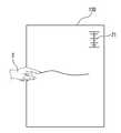
도 13을 참조하면, 터치패널(110)을 사용자가 제1객체(1)인 스타일러스펜이나 제2객체(2)인 핑거를 이용하여 터치하는데, 터치할 때 사용자가 터치패널(110)이 장착된 장치를 손으로 잡고 사용할 수 있다. 이때, 손바닥 등이 터치패널에 접촉하게 될 수 있는데, 손바닥이 터치패널(110)에 접촉한 부분(30)은 넓은 면적에 분포될 수 있다. 그리고, 제1객체(1) 또는 제2객체(2)를 이용하여 입력을 하고자 하는 부분은 작은 점(31,32,33,34) 형태로 배열될 수 있다. 즉, 손바닥이 터치패널(110)에 접촉되는 부분의 형태는 제1객체(1)나 제2객체(2)가 터치패널(110)에 접촉한 부분의 형태와 달리 넓게 퍼져있을 수 있다. 이러한 형태상의 차이를 이용하여 제어부(100)는 사용자가 손바닥 등으로 터치패널(110)을 잘못 터치한 부분을 배제할 수 있다. 또한, 사용자는 제1객체(1)을 사용하지 않는 경우 터치패널(110) 위에 놓을 수 있다. 이러한 경우도 터치된 형태가 선의 형태로 나타날 수 있고 이러한 형태 정보를 제어부(100)가 저장하고 있으면, 제어부(100)는 불필요한 터치를 인식하지 않을 수 있다. 제어부(100)는 형태 정보를 메모리부(340)에 저장할 수 있다.13, when the user touches the
도 14는 본 발명의 실시 예에 따른 터치패널 제어장치를 구비한 전자 장치를 도시한 사시도이다.FIG. 14 is a perspective view illustrating an electronic device including a touch panel control device according to an embodiment of the present invention.
도 14에 도시된 바와 같이, 본 발명의 실시 예에 따른 터치패널 제어장치는 터치패널(110)을 포함하는 휴대폰과 같은 전자 장치(1000)에 응용될 수 있다. 본 실시 예의 터치패널 제어장치는 터치패널(110)에 터치된 객체에 따라서 적어도 두 개의 터치동작모드를 각각 독립적으로 처리하므로, 다양한 기능을 동시에 구현하는 전자 장치(1000)의 효율성을 향상시키는 것에 유리하다.As shown in FIG. 14, the touch panel control apparatus according to the embodiment of the present invention can be applied to an
여기서, 상기 전자 장치(1000)는 도 14에 도시된 휴대폰에 한정되는 것이 아니며 예컨대, 모바일 전자 기기, 랩톱(laptop) 컴퓨터, 휴대용 컴퓨터, 포터블 멀티미디어 플레이어(PMP), 캠코더, 웹 태블릿(web tablet), 네비게이션, 개인 휴대용 정보 단말기(PDA; Personal Digital Assistant) 등 다양한 전자 기기를 포함할 수 있다.Here, the
이상에서 실시 예들에 설명된 특징, 구조, 효과 등은 본 발명의 적어도 하나의 실시 예에 포함되며, 반드시 하나의 실시 예에만 한정되는 것은 아니다. 나아가, 각 실시 예에서 예시된 특징, 구조, 효과 등은 실시 예들이 속하는 분야의 통상의 지식을 가지는 자에 의해 다른 실시 예들에 대해서도 조합 또는 변형되어 실시 가능하다. 따라서 이러한 조합과 변형에 관계된 내용들은 본 발명의 범위에 포함되는 것으로 해석되어야 할 것이다.The features, structures, effects and the like described in the embodiments are included in at least one embodiment of the present invention and are not necessarily limited to one embodiment. Further, the features, structures, effects, and the like illustrated in the embodiments can be combined and modified by other persons having ordinary skill in the art to which the embodiments belong. Therefore, it should be understood that the present invention is not limited to these combinations and modifications.
또한, 이상에서 실시 예를 중심으로 설명하였으나 이는 단지 예시일 뿐 본 발명을 한정하는 것이 아니며, 본 발명이 속하는 분야의 통상의 지식을 가진 자라면 본 실시예의 본질적인 특성을 벗어나지 않는 범위에서 이상에 예시되지 않은 여러 가지의 변형과 응용이 가능함을 알 수 있을 것이다. 예를 들어, 실시 예에 구체적으로 나타난 각 구성 요소는 변형하여 실시할 수 있는 것이다. 그리고 이러한 변형과 응용에 관계된 차이점들은 첨부된 청구 범위에서 규정하는 본 발명의 범위에 포함되는 것으로 해석되어야 할 것이다.
While the present invention has been particularly shown and described with reference to exemplary embodiments thereof, it is clearly understood that the same is by way of illustration and example only and is not to be taken by way of illustration, It can be seen that various modifications and applications are possible. For example, each component specifically shown in the embodiments can be modified and implemented. It is to be understood that all changes and modifications that come within the meaning and range of equivalency of the claims are therefore intended to be embraced therein.
10: 터치 패널 제어장치100: 제어부
110: 터치패널120: 압력센서
130: 표시부210: 터치프로세서
220: 응용프로세서310: 터치제어부
320: 구동부330: 터치신호감지부
340: 메모리부350: 압력신호감지부10: touch panel control device 100:
110: touch panel 120: pressure sensor
130: display unit 210: touch processor
220: application processor 310: touch controller
320: driving unit 330: touch signal sensing unit
340: memory unit 350: pressure signal sensing unit
Claims (27)
Translated fromKorean표시부; 및
상기 터치패널을 터치한 객체에 대응하여 상기 표시부에 객체의 터치 위치의 변화를 선으로 표시하는 제1터치동작모드와 상기 표시부에 표시된 선의 위치에 대응하는 객체의 위치변화에 대응하여 상기 표시부에 표시된 선의 적어도 일부의 제거 및 선의 색좌표변경 중 적어도 하나를 실행하는 제2터치동작모드를 수행하는 제어부를 포함하며,
상기 제어부는 상기 터치신호에 대응하여 객체가 상기 터치패널에 접촉하는 터치면적에 대응되는 유효터치영역의 정전용량 변화량에 대응하여 터치신호에 상기 제1터치동작모드 또는 상기 제2터치동작모드를 각각 독립적으로 설정하는 터치패널 제어장치.
A touch panel for generating at least one touch signal corresponding to a touch of an object;
A display section; And
A first touch operation mode for displaying a change in the touch position of the object on the display unit in a line corresponding to an object touched by the touch panel and a second touch operation mode for displaying a change in the position of the object corresponding to the position of the line displayed on the display unit And a second touch operation mode for performing at least one of removal of at least a portion of the line and change of the color coordinates of the line,
The control unit sets the first touch operation mode or the second touch operation mode to a touch signal corresponding to the capacitance change amount of the effective touch region corresponding to the touch area where the object touches the touch panel corresponding to the touch signal The touch panel control device is set independently.
상기 제어부는 상기 제1터치동작모드가 설정된 터치신호에 의해 제1터치동작모드를 수행하고 상기 제2터치동작모드가 설정된 터치신호에 의해 상기 제2터치동작모드를 수행하는 터치패널 제어장치.
The method according to claim 1,
Wherein the controller performs the first touch operation mode by the touch signal set in the first touch operation mode and performs the second touch operation mode according to the touch signal set in the second touch operation mode.
표시부; 및
상기 터치패널을 터치한 객체에 대응하여 상기 표시부에 객체의 터치 위치의 변화를 선으로 표시하는 제1터치동작모드와 상기 표시부에 표시된 선의 위치에 대응하는 객체의 위치변화에 대응하여 상기 표시부에 표시된 선의 적어도 일부의 제거 및 선의 색좌표변경 중 적어도 하나를 실행하는 제2터치동작모드를 수행하는 제어부를 포함하며,
상기 제어부는 터치프로세서와 응용프로세서를 포함하고,
상기 터치프로세서는 상기 터치신호에 대응하여 객체가 상기 터치패널에 접촉하는 터치면적에 대응되는 유효터치영역의 정전용량 변화량에 대응하여 터치신호에 상기 제1터치동작모드 또는 상기 제2터치동작모드를 각각 독립적으로 설정하고,
상기 응용프로세서는 상기 제1터치동작모드가 설정된 터치신호에 의해 제1터치동작모드를 수행하고 상기 제2터치동작모드가 설정된 터치신호에 의해 상기 제2터치동작모드를 수행하는 터치패널 제어장치.
A touch panel for generating at least one touch signal corresponding to a touch of an object;
A display section; And
A first touch operation mode for displaying a change in the touch position of the object on the display unit in a line corresponding to an object touched by the touch panel and a second touch operation mode for displaying a change in the position of the object corresponding to the position of the line displayed on the display unit And a second touch operation mode for performing at least one of removal of at least a portion of the line and change of the color coordinates of the line,
Wherein the control unit includes a touch processor and an application processor,
Wherein the touch processor outputs the first touch operation mode or the second touch operation mode to the touch signal corresponding to the capacitance change amount of the valid touch region corresponding to the touch area where the object touches the touch panel in response to the touch signal Respectively,
Wherein the application processor performs the first touch operation mode by the touch signal in which the first touch operation mode is set and performs the second touch operation mode by the touch signal in which the second touch operation mode is set.
표시부; 및
상기 터치패널을 터치한 객체에 대응하여 상기 표시부에 객체의 터치 위치의 변화를 선으로 표시하는 제1터치동작모드와 상기 표시부에 표시된 선의 위치에 대응하는 객체의 위치변화에 대응하여 상기 표시부에 표시된 선의 적어도 일부의 제거 및 선의 색좌표변경 중 적어도 하나를 실행하는 제2터치동작모드를 수행하는 제어부를 포함하며,
상기 제어부는 터치프로세서와 응용프로세서를 포함하고,
상기 터치프로세서는 상기 터치신호에 대응하여 객체가 상기 터치패널에 인가하는 압력분포에 대응되는 유효터치영역의 정전용량 변화량에 대응하여 터치신호에 상기 제1터치동작모드 또는 상기 제2터치동작모드를 각각 독립적으로 설정하고,
상기 응용프로세서는 상기 제1터치동작모드가 설정된 터치신호에 의해 제1터치동작모드를 수행하고 상기 제2터치동작모드가 설정된 터치신호에 의해 상기 제2터치동작모드를 수행하는 터치패널 제어장치.
A touch panel for generating at least one touch signal corresponding to a touch of an object;
A display section; And
A first touch operation mode for displaying a change in the touch position of the object on the display unit in a line corresponding to an object touched by the touch panel and a second touch operation mode for displaying a change in the position of the object corresponding to the position of the line displayed on the display unit And a second touch operation mode for performing at least one of removal of at least a portion of the line and change of the color coordinates of the line,
Wherein the control unit includes a touch processor and an application processor,
The touch processor may change the first touch operation mode or the second touch operation mode to a touch signal corresponding to the capacitance change amount of the valid touch region corresponding to the pressure distribution applied by the object to the touch panel in response to the touch signal Respectively,
Wherein the application processor performs the first touch operation mode by the touch signal in which the first touch operation mode is set and performs the second touch operation mode by the touch signal in which the second touch operation mode is set.
상기 제어부는 메모리부를 더 포함하고, 상기 메모리부에는 적어도 상기 제1터치동작모드, 상기 제2터치동작모드를 구분하기 위한 객체의 유효터치영역의 면적정보가 저장되는 터치패널 제어장치.
The method according to claim 1,
Wherein the control unit further includes a memory unit, and the memory unit stores the area information of the effective touch area of the object for distinguishing at least the first touch operation mode and the second touch operation mode.
상기 메모리부에는 복수의 상기 유효터치영역의 형태에 대한 형태정보를 저장하고, 상기 제어부는 상기 형태정보를 이용하여 유효터치여부를 파악하는 터치패널 제어장치.
The method according to claim 6,
Wherein the memory unit stores shape information of a plurality of the valid touch regions, and the controller determines whether the touch region is valid by using the shape information.
선의 적어도 일부가 제거되면 상기 표시부에 표시되는 선의 폭이 얇아지거나 선의 길이가 짧아지게 되는 터치패널 제어장치.
The method according to claim 1,
The width of the line displayed on the display unit becomes thin or the length of the line becomes short when at least a part of the line is removed.
상기 제어부는 상기 제1터치동작모드에 의해 상기 표시부에 표시하는 선의 두께를 객체가 상기 터치패널에 닿는 면적에 대응하여 결정하는 터치패널 제어장치.
The method according to claim 1,
Wherein the control unit determines the thickness of a line displayed on the display unit by the first touch operation mode in accordance with an area of an object touching the touch panel.
상기 제어부는 상기 제2터치동작모드에 의해 상기 표시부에 표시된 선의 폭을 제거하는 비율 또는 선의 색좌표를 다르게 설정하는 비율을 객체가 상기 터치패널에 닿는 면적에 대응하여 결정하는 터치패널 제어장치.
The method according to claim 1,
Wherein the control unit determines a ratio of removing a line width displayed on the display unit or a ratio of setting a color coordinate of a line differently according to an area of the object touching the touch panel by the second touch operation mode.
상기 장치는 상기 객체에 의해 상기 터치패널에 가해지는 압력을 인식하고 압력신호를 출력하는 압력센서를 더 포함하며, 상기 제어부는 상기 압력신호에 대응하여 상기 제1터치동작모드에서 표시되는 선의 두께 또는 선의 색좌표를 결정하고, 상기 제2터치동작모드에서 지워지는 선의 두께 또는 선의 색좌표를 결정하는 터치패널 제어장치.
The method according to claim 1,
The apparatus further includes a pressure sensor for recognizing a pressure applied to the touch panel by the object and outputting a pressure signal, wherein the controller is configured to control the touch panel in response to the pressure signal, Determines a color coordinate of a line, and determines a thickness of a line or a color coordinate of a line to be erased in the second touch operation mode.
상기 제어부는 상기 압력신호를 처리하는 압력신호감지부를 더 포함하는 터치패널 제어장치.
12. The method of claim 11,
Wherein the control unit further comprises a pressure signal sensing unit for processing the pressure signal.
상기 제어부는 상기 표시부에 상기 압력신호에 대응하는 압력정보를 더 표시하는 터치패널 제어장치.
12. The method of claim 11,
Wherein the control unit further displays pressure information corresponding to the pressure signal on the display unit.
상기 메모리부는 상기 제어부에 의해 상기 표시부에 표시되는 선의 좌표값에 대한 정보와 적어도 일부가 제거되거나 색좌표가 변경되는 선의 좌표값에 대한 정보를 각각 저장하는 터치패널 제어장치.
The method according to claim 6,
Wherein the memory unit stores information on coordinates of a line displayed on the display unit and information on coordinates of a line at least partially removed or changed in color coordinates by the control unit.
상기 제어부는 상기 유효터치영역내의 각각의 감지셀의 정전용량 변화량의 합, 상기 터치 영역 내에서 소정의 정전용량변화량을 넘는 감지셀의 개수, 상기 터치 영역 내에서 최대 정전용량 변화량 또는 최소 정전용량 변화량의 소정 비율을 넘는 감지셀의 개수, 상기 터치 영역 내의 정전용량 변화량 상위 및 하위 소정 개수의 정전용량 변화량의 합의 비율 중 어느 하나 이상을 소정의 임계치와 비교하여 상기 제1터치동작모드와 상기 제2터치동작모드 중 어느 하나에 해당하는지를 판단하는 터치패널 제어장치.
The method according to claim 1,
Wherein the control unit is configured to calculate the maximum capacitance change amount or the minimum capacitance change amount in the touch region, the sum of the capacitance change amounts of the respective sense cells in the valid touch region, the number of sense cells exceeding the predetermined capacitance change amount in the touch region, And a ratio of a sum of a capacitance change amount higher than a predetermined capacitance change amount in the touch region and a capacitance change amount in a lower predetermined number to a predetermined threshold value to determine whether the first touch operation mode and the second Touch operation mode of the touch panel.
상기 복수의 터치신호들 중 터치패널을 터치하는 객체의 터치위치 변화를 선을 표시하는 제1터치동작모드가 설정된 터치신호들을 이용하여 적어도 하나의 선을 표시하는 단계; 및
상기 복수의 터치신호들 중 상기 제1터치동작모드에 의해 표시된 선을 제거하거나 상기 표시된 선의 색좌표를 변경하는 제2터치동작모드가 설정된 터치신호들을 이용하여 제2터치동작모드를 수행하여 상기 제1터치동작모드에 의해 표시된 선 중 적어도 일부의 제거 또는 선의 색좌표 변경 중 적어도 하나를 수행하는 단계를 포함하며,
상기 제2터치동작모드는 객체가 일정시간 동안 상기 제1터치동작모드에 의해 표시된 복수의 선들이 교차되는 지점을 터치할 때, 상기 제1터치동작모드에서 표시된 역순으로 제거하는 터치패널 제어방법.
A touch panel control method for displaying a plurality of touch signals generated by touching a touch panel,
Displaying at least one line using touch signals having a first touch operation mode in which a line of a touch position change of an object touching the touch panel among the plurality of touch signals is set; And
A second touch operation mode is performed using touch signals having a second touch operation mode in which a line indicated by the first touch operation mode is removed or a color coordinate of the displayed line is changed among the plurality of touch signals, Performing at least one of removal of at least part of the lines displayed by the touch operation mode or changing of the color coordinates of the lines,
Wherein the second touch operation mode removes the object in a reverse order displayed in the first touch operation mode when touching a point where a plurality of lines displayed by the first touch operation mode intersect for a predetermined time.
상기 복수의 터치신호들 중 터치패널을 터치하는 객체의 터치위치 변화를 선을 표시하는 제1터치동작모드가 설정된 터치신호들을 이용하여 적어도 하나의 선을 표시하는 단계; 및
상기 복수의 터치신호들 중 상기 제1터치동작모드에 의해 표시된 선을 제거하거나 상기 표시된 선의 색좌표를 변경하는 제2터치동작모드가 설정된 터치신호들을 이용하여 제2터치동작모드를 수행하여 상기 제1터치동작모드에 의해 표시된 선 중 적어도 일부의 제거 또는 선의 색좌표 변경 중 적어도 하나를 수행하는 단계를 포함하며,
상기 제2터치동작모드 수행 후 선의 적어도 일부가 제거된 부분의 시작점과 끝점이 표시되고 상기 시작점과 상기 끝점을 잇는 구간이 터치되면, 상기 제2터치동작모드에서 제거된 선이 다시 표시되는 단계를 더 포함하는 터치패널 제어방법.
A touch panel control method for displaying a plurality of touch signals generated by touching a touch panel,
Displaying at least one line using touch signals having a first touch operation mode in which a line of a touch position change of an object touching the touch panel among the plurality of touch signals is set; And
A second touch operation mode is performed using touch signals having a second touch operation mode in which a line indicated by the first touch operation mode is removed or a color coordinate of the displayed line is changed among the plurality of touch signals, Performing at least one of removal of at least part of the lines displayed by the touch operation mode or changing of the color coordinates of the lines,
When a start point and an end point of a portion where at least a part of a line is removed after the execution of the second touch operation mode is displayed and a section between the start point and the end point is touched, a line removed in the second touch operation mode is displayed again Further comprising the steps of:
상기 복수의 터치신호들 중 터치패널을 터치하는 객체의 터치위치 변화를 선을 표시하는 제1터치동작모드가 설정된 터치신호들을 이용하여 적어도 하나의 선을 표시하는 단계; 및
상기 복수의 터치신호들 중 상기 제1터치동작모드에 의해 표시된 선을 제거하거나 상기 표시된 선의 색좌표를 변경하는 제2터치동작모드가 설정된 터치신호들을 이용하여 제2터치동작모드를 수행하여 상기 제1터치동작모드에 의해 표시된 선 중 적어도 일부의 제거 또는 선의 색좌표 변경 중 적어도 하나를 수행하는 단계를 포함하며,
선을 표시하는 동작을 수행할 때, 상기 제1터치동작모드에 의해 표시된 선이 교차하는 경우 교차된 지점의 선의 두께 또는 선의 색좌표는 교차하지 않은 지점보다 더 굵게 표시되는 터치패널 제어방법.
A touch panel control method for displaying a plurality of touch signals generated by touching a touch panel,
Displaying at least one line using touch signals having a first touch operation mode in which a line of a touch position change of an object touching the touch panel among the plurality of touch signals is set; And
A second touch operation mode is performed using touch signals having a second touch operation mode in which a line indicated by the first touch operation mode is removed or a color coordinate of the displayed line is changed among the plurality of touch signals, Performing at least one of removal of at least part of the lines displayed by the touch operation mode or changing of the color coordinates of the lines,
Wherein when the lines displayed by the first touch operation mode intersect, a thickness of a line at an intersecting point or a color coordinate of a line is displayed in a thicker manner than a point at which the intersection does not intersect.
상기 복수의 터치신호들 중 터치패널을 터치하는 객체의 터치위치 변화를 선을 표시하는 제1터치동작모드가 설정된 터치신호들을 이용하여 적어도 하나의 선을 표시하는 단계; 및
상기 복수의 터치신호들 중 상기 제1터치동작모드에 의해 표시된 선을 제거하거나 상기 표시된 선의 색좌표를 변경하는 제2터치동작모드가 설정된 터치신호들을 이용하여 제2터치동작모드를 수행하여 상기 제1터치동작모드에 의해 표시된 선 중 적어도 일부의 제거 또는 선의 색좌표 변경 중 적어도 하나를 수행하는 단계를 포함하며,
상기 제1터치동작모드와 상기 제2터치동작모드는 압력신호를 이용하여 표시되는 선의 두께 및 선의 색좌표가 결정되는 터치패널 제어방법.
A touch panel control method for displaying a plurality of touch signals generated by touching a touch panel,
Displaying at least one line using touch signals having a first touch operation mode in which a line of a touch position change of an object touching the touch panel among the plurality of touch signals is set; And
A second touch operation mode is performed using touch signals having a second touch operation mode in which a line indicated by the first touch operation mode is removed or a color coordinate of the displayed line is changed among the plurality of touch signals, Performing at least one of removal of at least part of the lines displayed by the touch operation mode or changing of the color coordinates of the lines,
Wherein the first touch operation mode and the second touch operation mode determine a line thickness and a line color coordinate using a pressure signal.
서로 다른 객체에 대응하여 상기 제1터치동작모드와 상기 제2터치동작모드를 각각 독립적으로 처리하되, 객체에 의해 발생된 터치신호가 객체의 터치위치의 변화를 선으로 표현하는 제1터치동작모드 입력조건 해당 여부를 판단하는 단계;
상기 터치신호가 상기 제1터치동작모드 입력조건의 해당 여부에 따라 상기 터치신호에 제1터치동작모드 플래그 및 제2터치동작모드 플래그 중 어느 하나를 설정하는 단계;
상기 플래그가 부여된 터치신호 중 연속된 터치신호에 동일한 인덱스를 부여하고, 상기 인덱스에 따라 상기 터치 스크린에의 다중의 동시적인 터치들을 검출 및 구별하는 단계; 및
상기 플래그와 상기 인덱스에 따라 터치신호를 처리하여 제1터치동작모드를 수행하도록 설정하거나, 상기 제2터치동작모드를 수행하여 상기 제1터치동작모드에서 표시된 선의 적어도 일부를 제거하거나 선의 색좌표를 변경하도록 설정하는 단계를 포함하며,
상기 터치신호의 제1터치동작모드 입력조건 해당 여부는 터치 영역내의 각각의 감지셀의 정전용량 변화량의 합, 상기 터치 영역 내에서 소정의 정전용량변화량을 넘는 감지셀의 개수, 상기 터치 영역 내에서 최대 정전용량 변화량 또는 최소 정전용량 변화량의 소정 비율을 넘는 감지셀의 개수, 상기 터치 영역 내의 정전용량 변화량 상위 및 하위 소정 개수의 정전용량 변화량의 합의 비율 중 어느 하나 이상을 비교하여 판단하는 터치 패널 제어방법.
Performing a first touch operation mode for displaying a change in touch position of an object in a line corresponding to an object touching the touch panel or performing a second touch operation mode for removing at least a part of a line displayed in the first touch operation mode In the touch panel control method,
A first touch operation mode in which the first touch operation mode and the second touch operation mode are independently performed in correspondence with different objects, Determining whether an input condition is satisfied;
Setting one of a first touch operation mode flag and a second touch operation mode flag in the touch signal according to whether the touch signal corresponds to the first touch operation mode input condition;
Assigning the same index to a continuous touch signal among the flagged touch signals and detecting and distinguishing multiple simultaneous touches to the touch screen according to the index; And
A touch operation is performed according to the flag and the index to perform a first touch operation mode or a second touch operation mode is performed to remove at least a part of a line displayed in the first touch operation mode, And,
Wherein the first touch operation mode input condition of the touch signal includes at least one of a sum of capacitance change amounts of the respective sense cells in the touch region, a number of sense cells exceeding a predetermined capacitance change amount in the touch region, A touch panel control for comparing and determining one or more of the number of sensing cells exceeding a predetermined ratio of the maximum capacitance change amount or the minimum capacitance change amount and the ratio of the sum of the capacitance change amount higher than the capacitance change amount in the touch region Way.
상기 제2터치동작모드는 상기 터치패널에 근접한 경우에 설정되는 터치패널 제어방법.
22. The method of claim 21,
Wherein the second touch operation mode is set when the second touch operation mode is close to the touch panel.
상기 제2터치동작모드는 객체가 일정시간 동안 상기 제1터치동작모드에 의해 표시된 복수의 선들이 교차되는 지점을 터치할 때, 상기 제1터치동작모드에서 표시된 역순으로 제거되도록 설정되는 터치패널 제어방법.
22. The method of claim 21,
Wherein the second touch operation mode is a touch panel control mode in which when an object touches a point where a plurality of lines displayed by the first touch operation mode intersect for a predetermined time, Way.
상기 제2터치동작모드 수행 후 상기 선의 적어도 일부가 제거된 부분의 시작점과 끝점이 표시되고 상기 시작점과 상기 끝점을 잇는 구간이 터치되면, 상기 제2터치동작모드에서 제거된 선이 다시 표시되도록 설정하는 단계를 더 포함하는 터치패널 제어방법.
22. The method of claim 21,
When a start point and an end point of a portion where at least a part of the line is removed after the execution of the second touch operation mode is displayed and an interval between the start point and the end point is touched, The method comprising the steps of:
상기 선을 표시하는 동작을 수행할 때, 상기 제1터치동작모드에 의해 표시된 선이 교차하는 경우 교차된 지점의 선의 두께 또는 선의 색좌표는 교차하지 않은 지점보다 더 굵게 표시되게 설정되는 터치패널 제어방법.
22. The method of claim 21,
Wherein when the line displayed by the first touch operation mode intersects, the thickness of the intersecting point or the color coordinate of the line is set to be thicker than the point where the intersection does not intersect when performing the operation of displaying the line .
상기 제1터치동작모드와 상기 제2터치동작모드는 압력신호를 이용하여 표시되는 선의 두께 및 선의 색좌표가 결정되는 터치패널 제어방법.
22. The method of claim 21,
Wherein the first touch operation mode and the second touch operation mode determine a line thickness and a line color coordinate using a pressure signal.
Priority Applications (2)
| Application Number | Priority Date | Filing Date | Title |
|---|---|---|---|
| KR1020130153168AKR101542799B1 (en) | 2013-12-10 | 2013-12-10 | Touch screen controller and method for controlling thereof |
| US14/565,746US9552095B2 (en) | 2013-12-10 | 2014-12-10 | Touch screen controller and method for controlling thereof |
Applications Claiming Priority (1)
| Application Number | Priority Date | Filing Date | Title |
|---|---|---|---|
| KR1020130153168AKR101542799B1 (en) | 2013-12-10 | 2013-12-10 | Touch screen controller and method for controlling thereof |
Publications (2)
| Publication Number | Publication Date |
|---|---|
| KR20150067569A KR20150067569A (en) | 2015-06-18 |
| KR101542799B1true KR101542799B1 (en) | 2015-08-07 |
Family
ID=53271152
Family Applications (1)
| Application Number | Title | Priority Date | Filing Date |
|---|---|---|---|
| KR1020130153168AActiveKR101542799B1 (en) | 2013-12-10 | 2013-12-10 | Touch screen controller and method for controlling thereof |
Country Status (2)
| Country | Link |
|---|---|
| US (1) | US9552095B2 (en) |
| KR (1) | KR101542799B1 (en) |
Cited By (1)
| Publication number | Priority date | Publication date | Assignee | Title |
|---|---|---|---|---|
| US11392253B2 (en) | 2020-02-14 | 2022-07-19 | Silicon Works Co., Ltd. | Touch sensing device for sensing active pen and touch sensing system including the same |
Families Citing this family (25)
| Publication number | Priority date | Publication date | Assignee | Title |
|---|---|---|---|---|
| US9459160B2 (en) | 2012-06-13 | 2016-10-04 | Microsoft Technology Licensing, Llc | Input device sensor configuration |
| US9684382B2 (en) | 2012-06-13 | 2017-06-20 | Microsoft Technology Licensing, Llc | Input device configuration having capacitive and pressure sensors |
| US10578499B2 (en) | 2013-02-17 | 2020-03-03 | Microsoft Technology Licensing, Llc | Piezo-actuated virtual buttons for touch surfaces |
| US9411436B2 (en) | 2013-09-20 | 2016-08-09 | Microsoft Technology Licensing, Llc | Input device backlighting |
| US9244579B2 (en)* | 2013-12-18 | 2016-01-26 | Himax Technologies Limited | Touch display apparatus and touch mode switching method thereof |
| US9448631B2 (en) | 2013-12-31 | 2016-09-20 | Microsoft Technology Licensing, Llc | Input device haptics and pressure sensing |
| JPWO2015174110A1 (en)* | 2014-05-14 | 2017-04-20 | ソニー株式会社 | Information processing apparatus, information processing method, and program |
| US10719132B2 (en)* | 2014-06-19 | 2020-07-21 | Samsung Electronics Co., Ltd. | Device and method of controlling device |
| KR101598412B1 (en) | 2015-02-11 | 2016-02-29 | 주식회사 하이딥 | Electrode sheet and touch input device |
| KR101739791B1 (en)* | 2015-05-11 | 2017-05-26 | 주식회사 하이딥 | Pressure sensor, pressure detector and touch input device including the same |
| US10222889B2 (en) | 2015-06-03 | 2019-03-05 | Microsoft Technology Licensing, Llc | Force inputs and cursor control |
| US10416799B2 (en) | 2015-06-03 | 2019-09-17 | Microsoft Technology Licensing, Llc | Force sensing and inadvertent input control of an input device |
| KR101765650B1 (en)* | 2015-08-03 | 2017-08-08 | 주식회사 하이딥 | Touch detector, touch detection chip and touch input device |
| KR20170022192A (en)* | 2015-08-19 | 2017-03-02 | 삼성전자주식회사 | Electronic device having the touch sensor |
| US10175807B2 (en)* | 2015-12-18 | 2019-01-08 | Stmicroelectronics Asia Pacific Pte Ltd | Support of narrow tip styluses on touch screen devices |
| CN110058782B (en)* | 2016-02-22 | 2020-11-24 | 广州视睿电子科技有限公司 | Touch operation method and system based on interactive electronic whiteboard |
| KR101964934B1 (en) | 2016-07-29 | 2019-04-04 | 삼성디스플레이 주식회사 | Display device and method for fabricating the same |
| EP3510476B1 (en)* | 2016-09-09 | 2021-08-25 | Sensel Inc. | System for detecting and characterizing inputs on a touch sensor |
| CN106168868B (en)* | 2016-09-30 | 2023-08-01 | 合肥鑫晟光电科技有限公司 | Shadow eliminating detection method and manufacturing method of touch substrate, touch substrate and touch device |
| CN106775090B (en)* | 2016-12-21 | 2022-03-11 | 北京汇冠触摸技术有限公司 | Infrared touch screen and gain adjustment method thereof |
| CN109144302B (en)* | 2017-06-28 | 2020-03-13 | 京东方科技集团股份有限公司 | Touch panel, touch method thereof and touch device |
| CN109753174A (en)* | 2017-11-06 | 2019-05-14 | 中华映管股份有限公司 | Touch device and touch signal processing method thereof |
| DE112018006732B4 (en)* | 2018-01-31 | 2022-03-10 | Mitsubishi Electric Corporation | TOUCH SCREEN DEVICE |
| US11886656B2 (en)* | 2019-04-10 | 2024-01-30 | Hideep Inc. | Electronic device and control method therefor |
| KR102714378B1 (en)* | 2020-03-18 | 2024-10-10 | 주식회사 엘엑스세미콘 | Touch sensing device and method thereof |
Family Cites Families (10)
| Publication number | Priority date | Publication date | Assignee | Title |
|---|---|---|---|---|
| JPH09190268A (en)* | 1996-01-11 | 1997-07-22 | Canon Inc | Information processing apparatus and method |
| US8134536B2 (en)* | 2007-05-15 | 2012-03-13 | Htc Corporation | Electronic device with no-hindrance touch operation |
| KR20100020389A (en) | 2008-08-12 | 2010-02-22 | 주식회사 케이티테크 | Input method using size of touching spot and device thereof |
| JP5516535B2 (en)* | 2011-08-25 | 2014-06-11 | コニカミノルタ株式会社 | Electronic information terminal and area setting control program |
| TW201316211A (en)* | 2011-10-13 | 2013-04-16 | Novatek Microelectronics Corp | Gesture detecting method capable of filtering panel mistouch |
| JP5810923B2 (en)* | 2012-01-06 | 2015-11-11 | 富士通株式会社 | Input device and touch position calculation method |
| US20140267078A1 (en)* | 2013-03-15 | 2014-09-18 | Adobe Systems Incorporated | Input Differentiation for Touch Computing Devices |
| US9377943B2 (en)* | 2013-05-30 | 2016-06-28 | Sony Corporation | Method and apparatus for outputting display data based on a touch operation on a touch panel |
| US9213424B1 (en)* | 2013-09-23 | 2015-12-15 | Amazon Technologies, Inc. | Stylus devices with eraser |
| JP2015114836A (en)* | 2013-12-11 | 2015-06-22 | キヤノン株式会社 | Image processing apparatus, tactile sensation control method, and program |
- 2013
- 2013-12-10KRKR1020130153168Apatent/KR101542799B1/enactiveActive
- 2014
- 2014-12-10USUS14/565,746patent/US9552095B2/enactiveActive
Cited By (1)
| Publication number | Priority date | Publication date | Assignee | Title |
|---|---|---|---|---|
| US11392253B2 (en) | 2020-02-14 | 2022-07-19 | Silicon Works Co., Ltd. | Touch sensing device for sensing active pen and touch sensing system including the same |
Also Published As
| Publication number | Publication date |
|---|---|
| US20150160778A1 (en) | 2015-06-11 |
| KR20150067569A (en) | 2015-06-18 |
| US9552095B2 (en) | 2017-01-24 |
Similar Documents
| Publication | Publication Date | Title |
|---|---|---|
| KR101542799B1 (en) | Touch screen controller and method for controlling thereof | |
| US10671280B2 (en) | User input apparatus, computer connected to user input apparatus, and control method for computer connected to user input apparatus, and storage medium | |
| US9846499B2 (en) | Touch panel and touch detection circuit | |
| KR101439855B1 (en) | Touch screen controller and method for controlling thereof | |
| KR101470903B1 (en) | Touch screen controller and method for controlling thereof | |
| CN107741824B (en) | Detection of gesture orientation on repositionable touch surface | |
| JP5106268B2 (en) | Touch panel | |
| CN102135829B (en) | Method for driving touch panel system | |
| JP2001222378A (en) | Touch panel input device | |
| US20100141591A1 (en) | Composite touch panel and method for operating the same | |
| JP2008217784A (en) | Touch panel | |
| CN101738765A (en) | Liquid crystal display panel with integrated touch screen, device and touch detection method | |
| US20110012864A1 (en) | Resistive touch panel and method for detecting touch point type | |
| US8947378B2 (en) | Portable electronic apparatus and touch sensing method | |
| CN103576997A (en) | Touch identification method of surface capacitive touch panel | |
| KR101438231B1 (en) | Terminal device having a hybrid touch screen and control method thereof | |
| KR101278283B1 (en) | Touch screen device | |
| US9996181B2 (en) | Information processing apparatus, information processing method, and program | |
| TWI460646B (en) | Resistive touch panel | |
| US20100033440A1 (en) | Sensing system | |
| US8860692B2 (en) | Touch pad and method for detecting multi-touch using the same | |
| JP5401295B2 (en) | Touch panel and coordinate position detection method |
Legal Events
| Date | Code | Title | Description |
|---|---|---|---|
| A201 | Request for examination | ||
| PA0109 | Patent application | Patent event code:PA01091R01D Comment text:Patent Application Patent event date:20131210 | |
| PA0201 | Request for examination | ||
| E902 | Notification of reason for refusal | ||
| PE0902 | Notice of grounds for rejection | Comment text:Notification of reason for refusal Patent event date:20141231 Patent event code:PE09021S01D | |
| PG1501 | Laying open of application | ||
| PE0701 | Decision of registration | Patent event code:PE07011S01D Comment text:Decision to Grant Registration Patent event date:20150731 | |
| GRNT | Written decision to grant | ||
| PR0701 | Registration of establishment | Comment text:Registration of Establishment Patent event date:20150803 Patent event code:PR07011E01D | |
| PR1002 | Payment of registration fee | Payment date:20150804 End annual number:3 Start annual number:1 | |
| PG1601 | Publication of registration | ||
| FPAY | Annual fee payment | Payment date:20180803 Year of fee payment:4 | |
| PR1001 | Payment of annual fee | Payment date:20180803 Start annual number:4 End annual number:4 | |
| PR1001 | Payment of annual fee | Payment date:20190801 Start annual number:5 End annual number:5 | |
| PR1001 | Payment of annual fee | Payment date:20200803 Start annual number:6 End annual number:6 | |
| PR1001 | Payment of annual fee | Payment date:20210802 Start annual number:7 End annual number:7 | |
| PR1001 | Payment of annual fee | Payment date:20220801 Start annual number:8 End annual number:8 | |
| PR1001 | Payment of annual fee | Payment date:20230801 Start annual number:9 End annual number:9 |