KR101541605B1 - Automatic fat suction apparatus - Google Patents
Automatic fat suction apparatusDownload PDFInfo
- Publication number
- KR101541605B1 KR101541605B1KR1020130136694AKR20130136694AKR101541605B1KR 101541605 B1KR101541605 B1KR 101541605B1KR 1020130136694 AKR1020130136694 AKR 1020130136694AKR 20130136694 AKR20130136694 AKR 20130136694AKR 101541605 B1KR101541605 B1KR 101541605B1
- Authority
- KR
- South Korea
- Prior art keywords
- tube
- vacuum
- cannula
- inner tube
- air
- Prior art date
- Legal status (The legal status is an assumption and is not a legal conclusion. Google has not performed a legal analysis and makes no representation as to the accuracy of the status listed.)
- Expired - Fee Related
Links
Images


Landscapes
- External Artificial Organs (AREA)
- Surgical Instruments (AREA)
Abstract
Translated fromKoreanDescription
Translated fromKorean본 발명은 지방을 흡입하여 제거하는 장치에 관한 것으로, 보다 상세하게는 지방 흡입 시술시 인체의 지방층에 삽입한 후 이를 진퇴시켜 왕복 운동하여 지방을 분리 및 파괴하고 이를 흡입하여 제거하는 자동 지방흡입장치에 관한 것이다.
The present invention relates to a device for sucking and removing fat, and more particularly, to an automatic liposuction device for inserting and removing fat, separating and destroying fat by reciprocating after being inserted into a fat layer of a human body during liposuction, .
일반적으로 지방흡입술(Liposuction)이란 우리 몸에 불만족스러운 비율이나 병적으로 비정상적인 비율로 많이 축적된 피하 지방을 흡입 제거하여 교정하는 수술 방법이다.In general, liposuction is an operation method that removes and removes subcutaneous fat accumulated in the body at an unsatisfactory rate or pathologically abnormal ratio.
이러한 지방흡입술을 이용하게 되면 장시간 동안 주기적으로 운동을 하거나 무리한 다이어트를 하지 않아도 우리 몸에 과도하게 축적된 지방을 보다 손쉽게 제거할 수 있고, 체내 지방과 체중이 감소되어 건강 증진 효과는 물론이고 몸매 개선의 효과도 얻을 수 있다.By using such liposuction, it is possible to easily remove excessively accumulated fat in the body without exercising periodically for a long period of time or without excessive diet, and it is possible to reduce the body fat and body weight, Can be obtained.
예컨대 도 1은 종래의 지방흡입장치를 도시한 도면인데, 내부에 흡입펌프(미도시)가 내장된 본체(1)가 구비되고, 본체(1)의 후방에는 지방저장통(2)이 설치되며, 지방저장통(2)은 흡입호스(3)를 통하여 캐뉼라(4b)의 배출관(4c)과 연결되고, 펌프호스(5)를 통하여 흡입펌프와 연결된다.For example, FIG. 1 shows a conventional liposuction device, which includes a main body 1 having a suction pump (not shown) built therein, an
또한, 본체(1)에는 흡입펌프의 세기 등을 설정할 수 있는 컨트롤판넬(6)이 구비되고, 지방 흡인력을 발생시키는 지방흡입기(7)도 설치되며, 본체(1)와는 별도로 지방흡입술 시술시 인체에 마취액을 주입하기 위한 인퓨전펌프(8)가 구비될 수 있다.The main body 1 is provided with a
더불어, 상기 흡입호스(3)는 핸드피스(4a)와 연결되고, 핸드피스(4a)의 선단에는 캐뉼라(4b)가 결합되며, 캐뉼라(4b)는 내부가 중공된 파이프 형상으로 이루어지고 선단에 다수의 흡입구가 형성된다.In addition, the
이때, 상기 핸드피스(4a)의 내부에는 캐뉼라(4b)를 진동시키기 위한 진동모터가 설치될 수도 있다.At this time, a vibration motor for vibrating the
이로써, 발판(9)을 눌러 장치를 작동시키면 흡입호스(3)를 통해 흡입력이 발생하고, 시술자가 핸드피스(4a)를 잡고 시술 부위에 캐뉼라(4b)를 찔러 삽입한 후 시술자가 지방흡입기(4)를 반복하여 전후진 시키거나 캐뉼라(4b)가 진동됨으로써, 지방이 분리되어 흡입구를 통해 흡입되고, 흡입된 지방은 캐뉼라(4b)의 내부에서 유동되어, 배출관(4c)을 거쳐 흡입호스(3)를 통해 배출되어 지방저장통(2)에 저장되는 것이다.Thus, when the device is operated by pressing the foot plate 9, a suction force is generated through the
그러나, 상술한 종래의 지방흡입장치는 시술자가 직접 핸드피스(4a)를 잡고 캐뉼라(4b)를 전후진 운동하여 지방을 분리해 내어 흡입 시술을 해야 하므로, 시술자의 시술경험이나 시술능력에 따라 시술 결과가 달라질 수 있고, 시술자의 피로도가 증가할 뿐만 아니라, 핸드피스(4a)가 신체의 피부면에 마찰되거나, 가늘고 긴 형태를 갖는 캐뉼라(4b)의 삽입부에 떨림 현상이 발생하여 정상 조직에 손상을 야기하거나 신경을 손상시킬 수 있는 문제가 있다.However, in the above-described conventional liposuction device, the practitioner directly grasps the handpiece 4a and moves the
또한, 시술 부위의 지방층 상태에 따라 일정한 양으로 지방을 흡입하기가 곤란하여 불규칙적으로 지방을 흡입하게 되는 문제가 있다.In addition, there is a problem that it is difficult to inhale the fat in a certain amount depending on the fat layer state of the treatment site, and the fat is irregularly inhaled.
그리고, 핸드피스(4a)에 내장된 진동모터를 이용하여 캐뉼라(4b)를 진동시켜 진동방식으로 지방을 흡입하게 되면, 시술자는 움직이지 않고 진동만 이루어지는 경우 시술 부위가 자극만 될 뿐 지방이 제거되지 않기 때문에, 시술자는 직접 캐뉼라(4b)를 전후진 운동하여 지방을 흡입 제거해야 되므로 상술한 바와 같은 동일한 문제가 발생한다.When the user uses the vibration motor built in the handpiece 4a to vibrate the
더불어, 진동에 의하여 캐뉼라(4b)의 삽입부의 주변의 조직이 손상되거나 무리하게 흡입을 하게 되고, 수술 후에도 부작용이 발생하게 되며, 피부가 울퉁불퉁하게 되어 시술 상태가 매끄럽지 못하게 되는 문제가 있다.
아울러, 종래기술로 일본 공개특허공보 특개2005-288187호(2005.10.20. 공개)가 있다.
In addition, the surrounding tissue of the insertion portion of the
Japanese Patent Application Laid-Open No. 2005-288187 (published on October 20, 2005) discloses a prior art.
본 발명은 상술한 문제들을 모두 해결하기 위하여 안출된 것으로, 캐뉼라가 이중관으로 이루어지고 작동부재에 의해 캐뉼라의 내측관을 자동으로 진퇴 왕복 운동시켜, 수동식 및 진동식 보다 떨림이나 진동이 적어 정확한 시술 부위에 대하여 지방흡입술을 시행할 수 있기 때문에, 주변 신체 조직의 손상 및 피부와 마찰에 의한 세포 괴사가 발생하지 않고, 시술 작업이 용이하여 시술자의 피로도가 대폭 감소되며, 시술 시간도 단축되고, 항상 일정한 시술 결과를 도출할 수 있어 편차가 줄어들며, 수술 후 시술 부위가 울퉁불퉁하지 않고 매끄럽게 유지되고, 수술 부작용이 최소화되는 자동 지방흡입장치의 제공에 그 목적이 있다.SUMMARY OF THE INVENTION The present invention has been conceived in order to solve all of the above-mentioned problems, and it is an object of the present invention to provide a cannula which is made of a double tube and which automatically reciprocates the inner tube of the cannula by the operation member, It is possible to perform liposuction, so that it is possible to prevent the damage of the surrounding body tissue and the cell necrosis caused by the skin and the friction. Therefore, the operation is easy and the fatigue of the practitioner is greatly reduced, the operation time is shortened, It is an object of the present invention to provide an automatic liposuction device in which the deviation can be deduced, the postoperative operation site can be maintained smoothly without being rugged, and the side effects of surgery can be minimized.
또한, 시술자가 한 손을 시술 부위에 올려 놓고 누르면서 압력을 가감시킴에 따라 진공흡입기의 진공게이지가 자동 변화되고, 이러한 진공게이지의 변화는 콘트롤박스를 통하여 솔레노이드밸브에 전달되어 에어실린더의 작동 속도가 자동으로 조절되므로, 시술 부위의 지방 흡입 위치와 지방 흡입량을 정확하게 결정하여 쉽고 빠르게 시술할 수 있는 자동 지방흡입장치의 제공에도 그 목적이 있다.In addition, the vacuum gauge of the vacuum inhaler is automatically changed as the practitioner puts one hand on the treatment site and presses the pressure on the treatment site, and the change of the vacuum gauge is transmitted to the solenoid valve through the control box, The present invention is also directed to an automatic liposuction device that can accurately and accurately determine the liposuction position and the amount of liposuction of the operation site.
그리고, 캐뉼라 대신에 디섹터를 장치에 결합시켜 시술 부위에 삽입하고, 섬유테를 고리관의 고리에 건 상태에서 고리관 내측의 커터를 전후진 움직여 섬유테를 용이하게 절단 제거할 수 있어 여러 기능을 갖는 자동 지방흡입장치의 제공에도 그 목적이 있다.
In addition, a disector is inserted into a device instead of a cannula, inserted into a treatment site, and a fibrous tissue is attached to a ring of a collar tube, and the cutter inside the collimator tube is moved back and forth to easily cut and remove the fibrous tissue. The object of the present invention is also to provide an automatic liposuction device.
상기 과제를 해결하기 위하여 본 발명은, 진공흡입기에서 발생하는 진공음압을 이용하여 체내에 축적된 지방을 흡입하여 제거하는 진공흡입장치에 있어서, 상부 외주에 길이 방향으로 유입공이 형성된 외측관과, 상기 외측관의 내부에 삽입되어 이동피스톤의 이동에 따라 함께 전후진 왕복 이동하고 상부 외주에 흡입공이 형성되어 지방을 흡입하는 내측관을 포함하는 캐뉼라; 상기 외측관의 하단에 연결되고, 내부에 이동공간이 형성된 연결관; 상기 내측관의 하단에 연결되고, 상기 연결관의 내부에서 왕복 이동하는 이동피스톤; 상기 이동피스톤의 하단과 연결되고, 내부에 상기 내측관과 연통된 흡입로가 형성되며, 작동부재의 내외로 인출입되는 작동로드; 상기 연결관의 하단에 연결되고, 상기 작동로드를 왕복 이동시키는 작동부재; 및 상기 작동로드의 하단에 연결되고, 상기 흡입로와 연통되도록 형성되며, 하단이 상기 진공흡입기의 흡입호스와 연결되어 흡입된 지방을 배출시키는 배출관;을 포함하는 자동 지방흡입장치를 제공한다.According to an aspect of the present invention, there is provided a vacuum inhaler for sucking and removing fat accumulated in a body by using a vacuum sound pressure generated in a vacuum inhaler, the vacuum inhaler comprising: an outer tube having an inlet hole formed in a longitudinal direction on an outer periphery thereof; A cannula inserted into the inside of the outer tube and reciprocating together with the movement of the moving piston, and an inner tube formed with a suction hole on the upper periphery to suck the fat; A connection pipe connected to a lower end of the outer tube and having a moving space therein; A moving piston connected to a lower end of the inner tube and reciprocating inside the connecting tube; An operating rod connected to a lower end of the moving piston and formed with a suction path communicated with the inner tube, and being drawn in and out of the operating member; An operation member connected to a lower end of the connection pipe and reciprocating the operation rod; And a discharge pipe connected to a lower end of the operation rod and connected to the suction hose of the vacuum inhaler, the lower end of the discharge pipe being connected to the suction path and discharging the inhaled fat.
게다가, 상기 작동부재는 상·하단에 에어가 유입 또는 배출되는 에어호스가 연결된 에어실린더인 것에도 그 특징이 있다.In addition, the operation member is also characterized in that it is an air cylinder to which an air hose through which air is introduced or discharged is connected to the upper and lower ends.
이때, 상기 에어호스는 솔레노이드밸브에 연결되어 에어 흐름의 조절에 의해 에어실린더를 작동시키는 것에도 그 특징이 있다.At this time, the air hose is also connected to the solenoid valve to operate the air cylinder by adjusting the air flow.
여기서, 상기 진공흡입기는 시술자가 한 손을 시술 부위에 올려 놓고 누르면서 압력을 가감시킴에 따라 진공게이지가 자동 변화되고, 상기 진공게이지의 변화는 콘트롤박스를 통하여 상기 솔레노이드밸브에 전달되어 상기 에어실린더에 공급 또는 배출되는 에어의 양이 조절되어 상기 에어실린더의 작동 속도를 조절하는 것에도 그 특징이 있다.Here, the vacuum gauge is automatically changed as the practitioner puts one hand on the treatment site and presses the vacuum inhaler, and the change of the vacuum gauge is transmitted to the solenoid valve through the control box, The amount of air supplied or discharged is controlled to control the operating speed of the air cylinder.
뿐만 아니라, 상기 외측관은 하단에 장착구가 형성되어 상기 연결관의 상단과 나사 결합된 것에도 그 특징이 있다.In addition, the outer tube is also characterized in that a mounting hole is formed at the lower end thereof and is screwed to the upper end of the connection tube.
더불어, 상기 내측관은 하단에 장착구가 형성되어 상기 이동피스톤의 상단과 나사 결합된 것에도 그 특징이 있다.In addition, the inner tube is also characterized in that a mounting hole is formed at the lower end thereof and is screwed to the upper end of the moving piston.
이와 함께, 상기 연결관은 상단에 나사돌부가 형성되고, 하단에 나사홀부가 형성되어 있는 것에도 그 특징이 있다.In addition, the connector has a threaded portion formed on the upper end thereof and a screw hole formed in the lower end thereof.
나아가, 상기 작동로드는 하단에 작동판이 결합되어 있는 것에도 그 특징이 있다.Further, the operation rod is also characterized in that the operation plate is coupled to the lower end.
또한, 상기 작동부재는 진공실린더인 것에도 그 특징이 있다.The operation member is also a vacuum cylinder.
그리고, 상기 작동부재는, 작동모터와, 상기 작동모터의 작동에 의하여 회전하는 피니언을 포함하고, 상기 작동로드가 상기 피니언과 맞물려 왕복 이동하는 것에도 그 특징이 있다.The operation member includes an operation motor and a pinion that rotates by the operation of the operation motor, and the operation rod reciprocally moves in engagement with the pinion.
아울러, 상기 캐뉼라를 분리시키고 디섹터(dissector)를 결합하여 사용 가능하되, 상기 디섹터는 선단부에 고리가 형성된 고리관과, 선단부에 절단날이 구비되어 상기 고리관의 내부에서 전후진 이동하여 절단을 수행하는 커터를 포함하는 것에도 그 특징이 있다.
In addition, the cannula may be separated and a dissector may be used. The dissector may include a ring tube having a ring formed at its distal end, and a cutting blade provided at a distal end thereof to move forward and backward within the ring tube, And a cutter for performing a cutting operation.
본 발명에 의하면, 캐뉼라가 이중관으로 이루어지고 작동부재에 의해 캐뉼라의 내측관을 자동으로 전후 왕복 운동시켜, 수동식 및 진동식 보다 떨림이나 진동이 적어 정확한 시술 부위에 대하여 지방흡입술을 시행할 수 있기 때문에, 주변 신체 조직의 손상 및 피부와 마찰에 의한 세포 괴사가 발생하지 않고, 시술 작업이 용이하여 시술자의 피로도가 대폭 감소되며, 시술 시간도 단축되고, 항상 일정한 시술 결과를 도출할 수 있어 편차가 줄어들며, 수술 후 시술 부위가 울퉁불퉁하지 않고 매끄럽게 유지되고, 수술 부작용이 최소화되는 효과가 있다.According to the present invention, since the cannula is made of a double tube and the inner tube of the cannula is automatically reciprocated back and forth by the operation member, liposuction treatment can be performed on the precise treatment site with less tremor or less vibration than the manual type and the oscillatory type, It is possible to reduce the degree of fatigue of the practitioner, shorten the procedure time, to always obtain a constant treatment result and to reduce the deviation, and to prevent the necrosis of the surrounding body tissue and the cell necrosis caused by the skin and friction, The post-operative treatment site is not rugged and remains smooth, and the side effects of surgery are minimized.
또한, 시술자가 한 손을 시술 부위에 올려 놓고 누르면서 압력을 가감시킴에 따라 진공흡입기의 진공게이지가 자동 변화되고, 이러한 진공게이지의 변화는 콘트롤박스를 통하여 솔레노이드밸브에 전달되어 에어실린더의 작동 속도가 자동으로 조절되므로, 시술 부위의 지방 흡입 위치와 지방 흡입량을 정확하게 결정하여 쉽고 빠르게 시술할 수 있는 효과도 있다.In addition, the vacuum gauge of the vacuum inhaler is automatically changed as the practitioner puts one hand on the treatment site and presses the pressure on the treatment site, and the change of the vacuum gauge is transmitted to the solenoid valve through the control box, So that the liposuction position and the amount of liposuction of the operation site can be accurately determined and the operation can be performed easily and quickly.
그리고, 캐뉼라 대신에 디섹터를 장치에 결합시켜 시술 부위에 삽입하고, 섬유테를 고리관의 고리에 건 상태에서 고리관 내측의 커터를 전후진 움직여 섬유테를 용이하게 절단 제거할 수 있는 효과도 있다.
Also, instead of the cannula, there is an effect that the dissecting device is coupled to the device and inserted into the treatment site, and the fibrous tissue is moved to the inside of the annular tube by moving the cutter inside the annular tube in the state of being hooked on the ring.
도 1은 종래의 지방흡입장치를 도시한 도면.
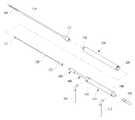
도 2는 본 발명에 따른 자동 지방흡입장치의 전체 구성에 대한 일실시예를 도시한 도면.
도 3은 본 발명에 따른 자동 지방흡입장치의 일부 측단면도.
도 4는 본 발명의 캐뉼라의 분리 사시도.
도 5는 본 발명에 따른 솔레노이드밸브의 작동 예시도
도 6은 본 발명에 따른 에어실린더의 작동 예시 단면도.
도 7은 본 발명에 따른 에어실린더의 작동 예시 사시도.
도 8은 작동부재가 작동모터와 피니언을 포함한 예시도.
도 9는 캐뉼라 대신 디섹터를 장착한 도면.1 is a view showing a conventional liposuction device;
2 is a view showing an entire configuration of an automatic liposuction device according to the present invention.
3 is a partial cross-sectional view of an automatic liposuction device according to the present invention.
4 is an exploded perspective view of the cannula of the present invention.
Fig. 5 is an operational example of the solenoid valve according to the present invention
6 is a sectional view showing an operation example of an air cylinder according to the present invention.
7 is a perspective view illustrating an operation example of an air cylinder according to the present invention.
8 is an exemplary view in which the operation member includes an operation motor and a pinion;
9 is a view of mounting a disector instead of a cannula.
이하, 도면을 참조하여 본 발명의 구성에 대하여 실시예를 중심으로 상세히 설명한다.Hereinafter, the configuration of the present invention will be described in detail with reference to the drawings with reference to the drawings.
본 발명에 따른 자동 지방흡입장치는 지방 흡입 시술시 인체의 지방층에 삽입한 후 이를 진퇴시켜 왕복 운동함으로써 지방을 분리 및 파괴하고 이를 흡입하여 제거하는 것으로, 도 2에 도시된 바와 같이 크게 캐뉼라(cannula; 100), 연결관(200), 이동피스톤(300), 작동로드(400), 작동부재(500)를 포함하여 이루어지고, 솔레노이드밸브(600), 콘트롤박스(700), 에어콤프레셔(800), 진공흡입기(900) 등이 함께 포함될 수 있다.The automatic liposuction device according to the present invention separates and destroys the fat by inserting the liposuction device into the fat layer of the human body and advancing and retracting the liposome by reciprocating the liposuction device. The automatic liposuction device sucks and removes the fat from the cannula, A
도 3 및 도 4에 도시된 바와 같이, 상기 캐뉼라(100)는 인체의 피하 지방층에 찔러 삽입되는 길이가 길고 직경이 협소한 관 형상을 갖는 것으로, 외부에 구비된 외측관(110)과 상기 외측관(110)의 내측에 삽입되는 내측관(120)의 이중관으로 이루어진다.3 and 4, the
상기 외측관(110)은 상부 외주에 길이 방향으로 유입공(111)이 관통 형성되어 캐뉼라(100)의 진퇴 왕복 운동에 의해 분리 및 파괴된 시술 부위의 지방이 관 내부로 유입되고, 하단에는 상기 연결관(200)의 상단과 나사 결합되는 장착구(122)가 형성된다.The
이때, 상기 유입공(111)은 길이가 긴 장공이고 타원형의 형태이며, 복수 개가 형성될 수도 있다.At this time, the
상기 내측관(120)은 상기 외측관(110)의 내부에 삽입되고, 상부 외주에 흡입공(121)이 관통 형성되며, 상기 유입공을 통해 상기 외측관(110)의 내부로 유입된 지방이 상기 흡입공(121)을 통하여 상기 내측관(120)의 내부로 흡입된다.The
상기 캐뉼라(100)가 진퇴 왕복 운동 중에 상기 외측관(110)의 유입공(111)과 상기 내측관(120)의 흡입공(121)이 서로 일치하여 겹치게 되는 경우 분리 및 파괴된 지방의 흡입이 가능하게 된다.When the
또한, 상기 내측관(120)은 하단에 장착구(122)가 형성되어 상기 이동피스톤(300)의 상단과 나사 결합된다.The
여기서, 상기 흡입공(121)은 복수 개가 형성될 수도 있다.Here, a plurality of
도 3에 도시된 바와 같이, 상기 연결관(200)은 상기 외측관(110)의 하단에 연결되어 상기 캐뉼라(100)와 상기 작동부재(500)의 사이에 형성되는 것으로, 내부에 이동피스톤(300)이 진퇴 왕복 운동하여 이동하는 이동공간(210)이 형성된다.3, the
또한, 상기 연결관(200)의 상단에 나사돌부(230)가 형성되어 상기 외측관(110)의 하단에 형성된 장착구(122)와 나사 결합되고, 상기 연결관(200)의 하단에 나사홀부(240)가 형성되어 상기 작동부재(500)의 상단으로 돌출된 상단돌부(미도시)와 나사 결합된다.A threaded
상기 이동피스톤(300)은 상기 내측관(120)의 하단에 연결되고, 상기 작동부재(500)의 작동에 의해 작동로드(400)까 왕복 이동하면, 그에 따라 상기 이동피스톤(300)도 왕복 이동한다.The moving
상기 작동로드(400)는 상기 이동피스톤(300)의 하단과 연결되고, 상기 작동부재(500)의 작동에 의하여 작동부재(500)의 내외로 인출입되며, 이로써 상기 작동로드(400)와 연결된 이동피스톤(300)이 상기 연결관(200)의 내부 이동공간(210)에서 진퇴 왕복 왕복 운동하여 수술 부위의 지방을 흡입하는 것이다.The
여기서, 상기 작동로드(400)는 하단에 작동판(410)이 결합되고, 상기 작동판(410)은 상기 작동부재(500)의 내부에서 이동하며, 상기 작동부재(500)의 내부 상단에서 걸림되도록 이루어진다.Here, the
상기 작동부재(500)는 상기 연결관(200)의 하단에 연결되고, 그 작동에 의하여 상기 작동로드(400)를 상하로 이동시켜, 상기 이동피스톤(300)를 반복적으로 왕복 운동시키는 작용을 한다.The
이때, 상기 작동부재(500)는 외부에서 공급된 공기의 압력이 갖는 에너지를 기계적인 왕복 직선 운동으로 변환하는 에어실린더(510)로 구성될 수 있다.At this time, the actuating
상기 에어실린더(510)는 내부가 중공 형성되고, 상·하단에 에어가 유입 또는 배출되는 상측 에어호스(511)와 하측 에어호스(512)가 연결되며, 상기 상측 에어호스(511)와 하측 에어호스(512)는 솔레노이드밸브(600)에 연결되어 에어 흐름을 조절함으로써 에어실린더의 작동이 이루어진다.The
상기 작동로드(400)의 하단에는 배출관(540)이 연결되고, 상기 배출관(540)은 상기 흡입로와 연통되도록 형성되며, 상기 배출관(540)의 하단이 상기 진공흡입기(900)의 흡입호스(910)와 연결되어 흡입된 지방을 상기 진공흡입기(900)의 지방저장통(930)으로 배출시켜 저장한다.A
이로써, 진공흡입기(900)의 흡입펌프(미도시)가 소정의 압력으로 잔공음압을 발생시키면, 상기 캐뉼라(100)의 내측관(120)을 통해 흡입된 지방이 상기 이동피스톤(300)과 작동로드(400)의 흡입로를 거쳐 상기 배출관(540)을 통하여 외부로 배출되며, 곧 상기 흡입호스(910)를 거쳐 지방저장통(930)에 저장되어 제거되는 것이다.When the suction pump (not shown) of the
예컨대, 일실시예로 설명하면, 상기 솔레노이드밸브(600)는 외부 전원을 공급하고 작동시간 등을 조절하는 콘트롤패널이 구비된 콘트롤박스(700)와 전기적으로 연결되고, 내부에 전자변이 구비된 일측의 헤드부(610)와, 외부의 에어콤프레셔(800)와 연결되어 에어를 공급하는 에어공급호스(513) 및 상기 상측 에어호스(511)와 하측 에어호스(512)가 연결된 연결부(620)와, 전기가 공급 또는 차단됨에 따라 개폐 작동되는 내부의 작동부(630)를 포함하여 이루어진다.For example, in one embodiment, the
나아가, 상기 진공흡입기(900)는 시술자가 한 손을 시술 부위에 올려 놓고 누르면서 압력을 가감시킴에 따라 진공게이지(vacuum indicator; 920)가 자동 변화되고, 상기 진공게이지(920)의 변화는 콘트롤박스(700)를 통하여 상기 솔레노이드밸브(600)에 전달되어 상기 에어실린더(510)에 공급 또는 배출되는 에어의 양이 조절되어 상기 에어실린더(510)의 작동 속도를 조절함으로써, 상기 캐뉼라(100)의 내측관(120)의 전후진 왕복 운동의 속도가 조절된다.In addition, the
또한, 상기 작동부재(500)는 반드시 에어실린더(510)에 한정되는 것은 아니고, 상기 에어실린더(510) 대신에 진공실린더가 설치될 수도 있고, 이동피스톤(300)을 왕복 운동시키는 작용을 할 수 있는 것이라면 그 밖에 다른 유형과 방식의 다양한 종류의 실린더도 적용될 수 있을 것이다.The actuating
더불어, 도 8에 도시된 바와 같이 다른 실시예로서 상기 작동부재(500)는, 그 내부에 작동모터(531)가 설치되고, 상기 작동모터(531)의 작동에 의하여 회전하는 피니언(532)이 연결 설치되며, 상기 작동로드(400)는 일측면에 치가 반복 형성되어 상기 피니언(532)과 맞물려 직선 방향으로 운동 가능하고, 상기 작동모터(531)를 정방향 또는 역방향으로 작동시킴에 의하여 상기 작동로드(400)가 왕복 이동할 수 있다.8, the actuating
아울러, 도 9에 도시된 바와 같이, 상기 캐뉼라를 분리시키고 디섹터(dissector; D)를 결합하여 사용 가능하되, 상기 디섹터(D)는 선단부에 고리가 형성된 고리관(D1)과, 선단부에 절단날이 구비되어 상기 고리관(D1)의 내부에서 전후진 이동하여 절단을 수행하는 커터(D2)를 포함한다.As shown in FIG. 9, the cannula may be separated and a dissector (D) may be used in combination. The dissector (D) includes a ring tube D1 having a ring at its tip, And a cutter (D2) provided with a cutting edge to move back and forth inside the annular tube (D1) to perform cutting.
상기 외측관(110) 및 내측관(120)은 각각 상기 연결관(200) 및 이동피스톤(300)과 쉽게 착탈될 수 있도록 결합되기 때문에, 상기 외측관(110) 및 내측관(120)을 분리시키고, 상기 연결관(200)에 고리관(D1)을 결합시키고, 상기 이동피스톤(300)에 커터(D2)를 결합시켜, 시술 부위의 섬유테를 절단 제거하는데 사용할 수 있다.The
즉, 지방흡입술 시술시 시술 부위의 피하에 질긴 섬유테(annulus fibrosus)가 그대로 남아 있는 경우 지방을 흡입 제거해도 시술부위의 부피가 줄어들지 않고 그대로 유지될 수 있기 때문에, 상기 캐뉼라(100)로 지방을 흡입 제거한 후, 상기 캐뉼라(100) 대신에 상기 디섹터(D)를 결합시켜 시술 부위에 삽입하고, 섬유테를 상기 고리관(D1)의 고리에 건 상태에서 상기 커터(D2)를 전후진 왕복 이동시켜 섬유테를 절단 제거하여 비만을 줄일 수 있는 것이다.That is, even if the annulus fibrosus is left intact under the treatment area during liposuction, the volume of the treatment area can be maintained without decreasing even if the fat is sucked and removed. Therefore, After the removal of the
이하, 도면을 참조하여 본 발명에 따른 자동 지방흡입장치의 작동에 대하여 일실시예를 통하여 상세히 설명한다.Hereinafter, the operation of the automatic liposuction device according to the present invention will be described in detail with reference to the accompanying drawings.
예컨대, 먼저 시술자는 에어콤프레셔(800)의 전원을 온(on) 작동시키고, 진공흡입기(900)의 전원을 온(on) 작동시키며, 콘트롤박스(700)의 전원도 온(on) 작동시켜 본 발명의 자동 진공흡입장치의 기기들을 작동시킨다.For example, the practitioner first turns on the power of the
그러면, 진공흡입기(900)의 흡입펌프가 작동되어 흡입호스(910)를 통해 진공음압이 발생하고, 에어콤프레셔(800)로부터 에어가 에어공급호스(513)를 통하여 솔레노이드밸브(600)로 공급되어 에어실린더(510)가 작동을 시작한다.Then, the suction pump of the
이후, 시술자는 한 손을 시술 부위에 올려 놓고 다른 한 손으로 연결관(200) 등을 잡고 캐뉼라(100)의 외측관(110)를 체내 시술 부위의 피하에 삽입시켜 지방을 제거하고자 하는 위치에 정확히 도달시킨다.Thereafter, the operator puts one hand on the treatment site, holds the
이때, 진공흡입기(900)의 0~76의 범위를 갖는 진공게이지(920)는 캐뉼라(100)를 체내에 삽입하지 않았을 때는 20을 유지하다가 체내에 삽입한 다음에는 증가하여 40에 이르게 되어, 에어실린더(510)가 작동을 시작하여 캐뉼라(100)의 내측관(120)의 전후진 왕복 이동이 시작되며, 예컨대 초당 0.5회 왕복 이동한다.At this time, the
다음에, 시술자가 시술 부위에 올려 놓은 손을 누르면서 압력을 가하거나 감하여 진공게이지(920)의 수치를 40 내지 60의 범위에서 가감시켜가며 에어실린더(510)의 작동 속도를 조절한다.Next, the operator adjusts the operating speed of the
즉, 시술자가 시술 부위에 올려 놓은 손을 누르면서 압력을 가하거나 감하게 되면 진공흡입기(900)의 진공게이지(920)의 수치가 변하게 되며, 이러한 진공게이지(920)의 수치 변화는 진공흡입기(900)와 전기적으로 연결된 콘트롤박스(700)를 통하여 곧 솔레노이드밸브(600)에 전달되며, 솔레노이드밸브(600)는 에어실린더(510)에 공급 또는 배출되는 에어의 양을 조절하여 에어실린더(510)의 작동 속도를 조절함으로써, 캐뉼라(100)의 내측관(120)의 전후진 왕복 이동의 속도를 조절하여며, 체내 시술 부위의 지방을 분리 및 파괴시키고 이를 흡입하여 흡입호스(910)를 통하여 지방저장통(930)으로 제거한다.That is, when a practitioner presses or depresses a hand put on a treatment site, the numerical value of the
이때, 도 5(a)에 도시된 바와 같이, 헤드부(610)의 전자변(611)에 전기적 신호가 가해지면 전자변(611)이 철심(612)을 당기게 되어 개폐구(613)를 열게 되고, 이때 공기의 압력으로 오링(631)을 밀게 되며, 에어콤프레셔(800)로부터 솔레노이드밸브(600)로 공급되어 연결부(620)의 공급홀(623)을 통해 유입된 에어가 하측 에어홀(622)로 흐르게 되고, 도 6(a) 및 도 7(a)와 같이 곧 에어가 하측 에어호스(512)를 통하여 에어실린더(510)의 내부로 유입되므로, 작동로드(400)가 전진된 상태가 된다.5 (a), when an electrical signal is applied to the
도 5(b)에 도시된 바와 같이, 반대로 전기적 신호가 끊기게 되면 개폐구(613)가 닫히면서 오링(631)에 공기의 압력이 사라지게 되어 스프링(632)의 힘으로 유동된 오링(631)이 원래의 위치로 복원되고, 연결부(620)의 공급홀(623)을 통해 솔레노이드밸브(600)로 공급 유입된 에어가 상측 에어홀(621)로 흐르게 되며, 도 6(b) 및 도 7(b)와 같이 곧 에어가 상측 에어호스(511)를 통하여 에어실린더(510)의 내부로 유입되므로, 작동로드(400)가 후퇴된 상태가 된다.5 (b), when the electrical signal is shut off, the air pressure is lost in the O-
이와 같이, 솔레노이드밸브(600)의 개폐 작용에 의하여 에어의 흐름이 조절되어 에어실린더(510)가 작동되고, 작동로드(400)가 반복적으로 진퇴 왕복 운동함으로써 캐뉼라(100)의 내측관(120)이 왕복 운동을 하게 되며, 캐뉼라(100)가 왕복 운동 중에 외측관(110)의 유입공(111)과 내측관(120)의 흡입공(121)이 서로 일치하여 겹치게 되는 경우 지방이 흡입되는 것이다..The
또한, 시술자가 한 손을 시술 부위에 올려 놓고 누르면서 압력을 가감시킴에 따라 진공흡입기(900)의 진공게이지(920)의 수치가 자동으로 변화되고, 이러한 진공게이지(920)의 수치 변화는 콘트롤박스(700)를 통하여 솔레노이드밸브(600)에 전달되어 에어실린더(510)의 작동 속도가 자동으로 조절되므로, 시술 부위의 지방 흡입 위치와 지방 흡입량을 정확하게 결정하여 쉽고 빠르게 시술할 수 있다.Also, as the practitioner puts one hand on the treatment site and presses the pressure on the treatment site, the pressure of the
한편, 시술 부위의 피하에 질긴 섬유테가 남아 있어 이를 제거하고자 하는 경우, 캐뉼라(100)를 장치로부터 분리시킨 후 절단 도구인 디섹터(dissector; D)를 장치에 결합하여 섬유테를 절단 제거한다.Meanwhile, when a tough fibrous tissue is left under the surgical site to remove it, the
결국, 본 발명에 따른 자동 지방흡입장치는 캐뉼라가 이중관으로 이루어지고 작동부재에 의해 캐뉼라의 내측관을 자동으로 진퇴 왕복 운동시켜, 수동식 및 진동식 보다 떨림이나 진동이 적어 정확한 시술 부위에 대하여 지방흡입술을 시행할 수 있기 때문에, 주변 신체 조직의 손상 및 피부와 마찰에 의한 세포 괴사가 발생하지 않고, 시술 작업이 용이하여 시술자의 피로도가 대폭 감소되며, 시술 시간도 단축되고, 항상 일정한 시술 결과를 도출할 수 있어 편차가 줄어들며, 수술 후 시술 부위가 울퉁불퉁하지 않고 매끄럽게 유지되고, 수술 부작용이 최소화되는 것이다.As a result, the automatic liposuction device according to the present invention has a cannula as a double tube, and the inner tube of the cannula is automatically reciprocated and moved by the operation member, so that liposuction Therefore, it is possible to reduce the fatigue of the practitioner, shorten the procedure time, and always produce a constant treatment result without causing damage to the surrounding body tissue and cell necrosis caused by skin and friction. The amount of deviation is reduced, the post-operative treatment site is not rugged, is kept smooth, and the side effects of surgery are minimized.
본 발명에서 상기 실시 형태는 하나의 예시로서 본 발명이 여기에 한정되는 것은 아니다. 본 발명의 특허청구범위에 기재된 기술적 사상과 실질적으로 동일한 구성을 갖고 동일한 작용효과를 이루는 것은 어떠한 것이라도 본 발명의 기술적 범위에 포함된다.
The present invention is not limited to the above-described embodiments. Anything having substantially the same constitution as the technical idea described in the claims of the present invention and achieving the same operational effect is included in the technical scope of the present invention.
1. 본체 2. 지방저장통
3. 흡입호스 4a. 핸드피스
4b. 캐뉼라 4c. 배출관
5. 펌프호스 6. 컨트롤판넬
7. 지방흡입기 8. 인퓨전펌프
9. 발판 100. 캐뉼라(cannula)
110. 외측관 111. 유입공
112. 장착구 120. 내측관
121. 흡입공 122. 장착구
200. 연결관 210. 이동공간
230. 나사돌부 240. 나사홀부
300. 이동피스톤 400. 작동로드
410. 작동판 500. 작동부재
510. 에어실린더 511. 상측 에어호스
512. 하측 에어호스 513. 에어공급호스
531. 작동모터 532. 피니언
540. 배출관 600. 솔레노이드밸브
610. 헤드부 611. 전자변
612. 철심 613. 개폐구
620. 연결부 621. 상측 에어홀
622. 하측 에어홀 623. 공급홀
630. 작동부 631. 오링
632. 스프링 700. 콘트롤박스
800. 에어콤프레셔 900. 진공흡입기
910. 흡입호스 920. 진공게이지
930. 지방저장통 D. 디섹터(dissector)
D1. 고리관 D2. 커터1.
3. Suction hose 4a. Handpiece
4b.
5.
7.
9.
110.
112. Mounting
121.
200.
230. threaded
300.
410.
510.
512.
531.
540.
610.
612.
620.
622
630.
632.
800.
910.
930. fat reservoir D. dissector
D1. Ring tube D2. cutter
Claims (11)
Translated fromKorean상부 외주에 길이 방향으로 유입공이 형성된 외측관과, 상기 외측관의 내부에 삽입되어 이동피스톤의 이동에 따라 함께 전후진 왕복 이동하고 상부 외주에 흡입공이 형성되어 지방을 흡입하는 내측관을 포함하는 캐뉼라; 상기 외측관의 하단에 연결되고, 내부에 이동공간이 형성된 연결관; 상기 내측관의 하단에 연결되고, 상기 연결관의 내부에서 왕복 이동하는 이동피스톤; 상기 이동피스톤의 하단과 연결되고, 내부에 상기 내측관과 연통된 흡입로가 형성되며, 작동부재의 내외로 인출입되는 작동로드; 상기 연결관의 하단에 연결되고, 상기 작동로드를 왕복 이동시키는 작동부재; 및 상기 작동로드의 하단에 연결되고, 상기 흡입로와 연통되도록 형성되며, 하단이 상기 진공흡입기의 흡입호스와 연결되어 흡입된 지방을 배출시키는 배출관;을 포함하되,
상기 작동부재는 상·하단에 에어가 유입 또는 배출되는 에어호스가 연결된 에어실린더이고, 상기 에어호스는 솔레노이드밸브에 연결되어 에어 흐름의 조절에 의해 에어실린더를 작동시키며,
상기 진공흡입기는 시술자가 한 손을 시술 부위에 올려 놓고 누르면서 압력을 가감시킴에 따라 진공게이지가 자동 변화되고, 상기 진공게이지의 변화는 콘트롤박스를 통하여 상기 솔레노이드밸브에 전달되어 상기 에어실린더에 공급 또는 배출되는 에어의 양이 조절되어 상기 에어실린더의 작동 속도를 조절하는 것을 특징으로 하는 자동 지방흡입장치.
1. A vacuum inhalation device for sucking and removing fat accumulated in a body using a vacuum negative pressure generated in a vacuum inhaler,
A cannula including an inner tube inserted into the outer tube and reciprocating back and forth together with the movement of the moving piston and formed with a suction hole on an outer periphery of the upper part, ; A connection pipe connected to a lower end of the outer tube and having a moving space therein; A moving piston connected to a lower end of the inner tube and reciprocating inside the connecting tube; An operating rod connected to a lower end of the moving piston and formed with a suction path communicated with the inner tube, and being drawn in and out of the operating member; An operation member connected to a lower end of the connection pipe and reciprocating the operation rod; And a discharge pipe connected to a lower end of the operation rod and connected to the suction hose of the vacuum inhaler, the lower end of the discharge pipe communicating with the suction path, and discharging the sucked fat,
Wherein the operating member is an air cylinder connected to an air hose through which air is introduced or discharged at upper and lower ends, the air hose being connected to a solenoid valve to operate the air cylinder by adjusting the air flow,
The vacuum gauge is automatically changed as the practitioner puts one hand on the treatment site and presses the vacuum inhaler, and the change of the vacuum gauge is transmitted to the solenoid valve through the control box, Wherein an amount of air to be discharged is adjusted to adjust an operating speed of the air cylinder.
상기 외측관은 하단에 장착구가 형성되어 상기 연결관의 상단과 나사 결합된 것을 특징으로 하는 자동 지방흡입장치.
The method according to claim 1,
Wherein the outer tube is formed with a mounting hole at the lower end thereof and is screwed to an upper end of the connection tube.
상기 내측관은 하단에 장착구가 형성되어 상기 이동피스톤의 상단과 나사 결합된 것을 특징으로 하는 자동 지방흡입장치.
The method according to claim 1,
Wherein the inner tube is formed with a mounting hole at a lower end thereof and is screwed with an upper end of the moving piston.
상기 연결관은 상단에 나사돌부가 형성되고, 하단에 나사홀부가 형성되어 있는 것을 특징으로 하는 자동 지방흡입장치.
The method according to claim 1,
Wherein the connecting pipe is formed with a threaded portion at an upper end thereof and a screw hole formed at a lower end thereof.
상기 작동로드는 하단에 작동판이 결합되어 있는 것을 특징으로 하는 자동 지방흡입장치.
The method according to claim 1,
Wherein the operation rod is coupled to an operation plate at a lower end thereof.
상기 작동부재는 진공실린더인 것을 특징으로 하는 자동 지방흡입장치.
The method according to claim 1,
Wherein the operating member is a vacuum cylinder.
상기 작동부재는, 작동모터와, 상기 작동모터의 작동에 의하여 회전하는 피니언을 포함하고, 상기 작동로드가 상기 피니언과 맞물려 왕복 이동하는 것을 특징으로 하는 자동 지방흡입장치.
The method according to claim 1,
Wherein the operating member includes an operating motor and a pinion that rotates by the operation of the operating motor, and the operating rod reciprocally moves in engagement with the pinion.
상기 캐뉼라를 분리시키고 디섹터(dissector)를 결합하여 사용 가능하되,
상기 디섹터는 선단부에 고리가 형성된 고리관과, 선단부에 절단날이 구비되어 상기 고리관의 내부에서 전후진 이동하여 절단을 수행하는 커터를 포함하는 자동 지방흡입장치.
The method according to claim 1,
The cannula is separated and a dissector is combined,
And a cutter having a cutting edge at a distal end thereof and moving back and forth in the inside of the annular tube to perform cutting.
Priority Applications (1)
| Application Number | Priority Date | Filing Date | Title |
|---|---|---|---|
| KR1020130136694AKR101541605B1 (en) | 2013-11-12 | 2013-11-12 | Automatic fat suction apparatus |
Applications Claiming Priority (1)
| Application Number | Priority Date | Filing Date | Title |
|---|---|---|---|
| KR1020130136694AKR101541605B1 (en) | 2013-11-12 | 2013-11-12 | Automatic fat suction apparatus |
Publications (2)
| Publication Number | Publication Date |
|---|---|
| KR20150054347A KR20150054347A (en) | 2015-05-20 |
| KR101541605B1true KR101541605B1 (en) | 2015-08-03 |
Family
ID=53390519
Family Applications (1)
| Application Number | Title | Priority Date | Filing Date |
|---|---|---|---|
| KR1020130136694AExpired - Fee RelatedKR101541605B1 (en) | 2013-11-12 | 2013-11-12 | Automatic fat suction apparatus |
Country Status (1)
| Country | Link |
|---|---|
| KR (1) | KR101541605B1 (en) |
Cited By (4)
| Publication number | Priority date | Publication date | Assignee | Title |
|---|---|---|---|---|
| KR20190119933A (en) | 2018-04-13 | 2019-10-23 | 주식회사 삼육오엠씨네트웍스 | Balance adjustment apparatus of liposuction site |
| KR20200131039A (en) | 2019-05-13 | 2020-11-23 | 주식회사 삼육오엠씨네트웍스 | Real-time liposuction situation check apparatus |
| KR20210000199U (en)* | 2020-03-11 | 2021-01-26 | 재단법인 대구경북첨단의료산업진흥재단 | Medical cannula with multiple structures |
| KR102420056B1 (en) | 2022-03-23 | 2022-07-12 | 이영복 | Pneumatic Distributor |
Families Citing this family (5)
| Publication number | Priority date | Publication date | Assignee | Title |
|---|---|---|---|---|
| KR102530666B1 (en)* | 2021-01-04 | 2023-05-11 | 주식회사 엘에이치바이오메드 | Power assisted liposuction device |
| KR102562165B1 (en)* | 2021-01-12 | 2023-08-02 | 주식회사 삼육오엠씨(365mc) | Cannula for fat inhalalation |
| KR102537315B1 (en)* | 2021-01-19 | 2023-05-30 | 주식회사 삼육오엠씨(365mc) | Apparatus and handpiece for fat inhalalation |
| KR102703400B1 (en)* | 2021-02-17 | 2024-09-06 | 주식회사 삼육오엠씨(365mc) | Apparatus and handpiece for fat inhalalation |
| CN114939195A (en)* | 2022-05-12 | 2022-08-26 | 陆云 | Safe and reliable facial liposuction system for plastic cosmetology department and use method thereof |
Citations (3)
| Publication number | Priority date | Publication date | Assignee | Title |
|---|---|---|---|---|
| JP2005288187A (en)* | 1995-02-10 | 2005-10-20 | Biopsys Medical Inc | Method and device for automated biopsy and collection of soft tissue |
| KR100913378B1 (en) | 2008-10-22 | 2009-08-20 | (주)에스덤메딕스 | Liposuction Cannula |
| US20120277624A1 (en)* | 2009-08-05 | 2012-11-01 | Cucin Robert L | Method of collecting and in situ processing of aspirated fat tissue sampled from a human patient during tissue aspiration operations |
- 2013
- 2013-11-12KRKR1020130136694Apatent/KR101541605B1/ennot_activeExpired - Fee Related
Patent Citations (3)
| Publication number | Priority date | Publication date | Assignee | Title |
|---|---|---|---|---|
| JP2005288187A (en)* | 1995-02-10 | 2005-10-20 | Biopsys Medical Inc | Method and device for automated biopsy and collection of soft tissue |
| KR100913378B1 (en) | 2008-10-22 | 2009-08-20 | (주)에스덤메딕스 | Liposuction Cannula |
| US20120277624A1 (en)* | 2009-08-05 | 2012-11-01 | Cucin Robert L | Method of collecting and in situ processing of aspirated fat tissue sampled from a human patient during tissue aspiration operations |
Cited By (5)
| Publication number | Priority date | Publication date | Assignee | Title |
|---|---|---|---|---|
| KR20190119933A (en) | 2018-04-13 | 2019-10-23 | 주식회사 삼육오엠씨네트웍스 | Balance adjustment apparatus of liposuction site |
| KR20200131039A (en) | 2019-05-13 | 2020-11-23 | 주식회사 삼육오엠씨네트웍스 | Real-time liposuction situation check apparatus |
| KR20210000199U (en)* | 2020-03-11 | 2021-01-26 | 재단법인 대구경북첨단의료산업진흥재단 | Medical cannula with multiple structures |
| KR200495284Y1 (en)* | 2020-03-11 | 2022-04-18 | 재단법인 대구경북첨단의료산업진흥재단 | Medical cannula with multiple structures |
| KR102420056B1 (en) | 2022-03-23 | 2022-07-12 | 이영복 | Pneumatic Distributor |
Also Published As
| Publication number | Publication date |
|---|---|
| KR20150054347A (en) | 2015-05-20 |
Similar Documents
| Publication | Publication Date | Title |
|---|---|---|
| KR101541605B1 (en) | Automatic fat suction apparatus | |
| KR102782067B1 (en) | Ophthalmic cutting device with integral suction pump | |
| US11638660B2 (en) | Ophthalmic microsurgical tools, systems, and methods of use | |
| CN114206277B (en) | Multi-stage trigger for ophthalmic cutting tools | |
| EP2384175B1 (en) | System for operating and controlling a pneumatically driven vitrectomy probe | |
| US5853384A (en) | Fluid jet surgical cutting tool and aspiration device | |
| US11679029B2 (en) | Electronic guillotine vitrectomy cutter | |
| US20090204022A1 (en) | Pneumatic Circuit and Biopsy Device | |
| US6213971B1 (en) | Power assisted liposuction device | |
| WO1997046164A1 (en) | An apparatus and method for performing ophthalmic procedures | |
| CN1120805A (en) | Method and apparatus for invasive tissue removal | |
| JP2001087303A (en) | Ophthalmic surgery apparatus | |
| WO2000078371A1 (en) | An apparatus and method for performing ophthalmic procedures | |
| EP0484050B1 (en) | System and apparatus for controlling fluid flow to and from a surgical site | |
| WO2016182095A1 (en) | Automatic fat suction device | |
| CN104645489A (en) | Micro water shooting dropper | |
| HK1162297B (en) | System for operating and controlling a pneumatically driven vitrectomy probe |
Legal Events
| Date | Code | Title | Description |
|---|---|---|---|
| A201 | Request for examination | ||
| PA0109 | Patent application | St.27 status event code:A-0-1-A10-A12-nap-PA0109 | |
| PA0201 | Request for examination | St.27 status event code:A-1-2-D10-D11-exm-PA0201 | |
| D13-X000 | Search requested | St.27 status event code:A-1-2-D10-D13-srh-X000 | |
| D14-X000 | Search report completed | St.27 status event code:A-1-2-D10-D14-srh-X000 | |
| E902 | Notification of reason for refusal | ||
| PE0902 | Notice of grounds for rejection | St.27 status event code:A-1-2-D10-D21-exm-PE0902 | |
| P11-X000 | Amendment of application requested | St.27 status event code:A-2-2-P10-P11-nap-X000 | |
| P13-X000 | Application amended | St.27 status event code:A-2-2-P10-P13-nap-X000 | |
| R15-X000 | Change to inventor requested | St.27 status event code:A-3-3-R10-R15-oth-X000 | |
| R16-X000 | Change to inventor recorded | St.27 status event code:A-3-3-R10-R16-oth-X000 | |
| E13-X000 | Pre-grant limitation requested | St.27 status event code:A-2-3-E10-E13-lim-X000 | |
| P11-X000 | Amendment of application requested | St.27 status event code:A-2-2-P10-P11-nap-X000 | |
| P13-X000 | Application amended | St.27 status event code:A-2-2-P10-P13-nap-X000 | |
| N231 | Notification of change of applicant | ||
| PN2301 | Change of applicant | St.27 status event code:A-3-3-R10-R11-asn-PN2301 St.27 status event code:A-3-3-R10-R13-asn-PN2301 | |
| E701 | Decision to grant or registration of patent right | ||
| PE0701 | Decision of registration | St.27 status event code:A-1-2-D10-D22-exm-PE0701 | |
| PG1501 | Laying open of application | St.27 status event code:A-1-1-Q10-Q12-nap-PG1501 | |
| GRNT | Written decision to grant | ||
| PR0701 | Registration of establishment | St.27 status event code:A-2-4-F10-F11-exm-PR0701 | |
| PR1002 | Payment of registration fee | Fee payment year number:1 St.27 status event code:A-2-2-U10-U11-oth-PR1002 | |
| PG1601 | Publication of registration | St.27 status event code:A-4-4-Q10-Q13-nap-PG1601 | |
| FPAY | Annual fee payment | Payment date:20180731 Year of fee payment:4 | |
| PR1001 | Payment of annual fee | Fee payment year number:4 St.27 status event code:A-4-4-U10-U11-oth-PR1001 | |
| PR1001 | Payment of annual fee | Fee payment year number:5 St.27 status event code:A-4-4-U10-U11-oth-PR1001 | |
| R18-X000 | Changes to party contact information recorded | St.27 status event code:A-5-5-R10-R18-oth-X000 | |
| PR1001 | Payment of annual fee | Fee payment year number:6 St.27 status event code:A-4-4-U10-U11-oth-PR1001 | |
| PR1001 | Payment of annual fee | Fee payment year number:7 St.27 status event code:A-4-4-U10-U11-oth-PR1001 | |
| PC1903 | Unpaid annual fee | Not in force date:20220729 Payment event data comment text:Termination Category : DEFAULT_OF_REGISTRATION_FEE St.27 status event code:A-4-4-U10-U13-oth-PC1903 | |
| PC1903 | Unpaid annual fee | Ip right cessation event data comment text:Termination Category : DEFAULT_OF_REGISTRATION_FEE Not in force date:20220729 St.27 status event code:N-4-6-H10-H13-oth-PC1903 | |
| R18-X000 | Changes to party contact information recorded | St.27 status event code:A-5-5-R10-R18-oth-X000 | |
| R18-X000 | Changes to party contact information recorded | St.27 status event code:A-5-5-R10-R18-oth-X000 |