KR101537742B1 - Beacon and Listner for Indoor Positioning System - Google Patents
Beacon and Listner for Indoor Positioning SystemDownload PDFInfo
- Publication number
- KR101537742B1 KR101537742B1KR1020140100096AKR20140100096AKR101537742B1KR 101537742 B1KR101537742 B1KR 101537742B1KR 1020140100096 AKR1020140100096 AKR 1020140100096AKR 20140100096 AKR20140100096 AKR 20140100096AKR 101537742 B1KR101537742 B1KR 101537742B1
- Authority
- KR
- South Korea
- Prior art keywords
- ultrasonic
- unit
- listener
- signal
- beacon
- Prior art date
- Legal status (The legal status is an assumption and is not a legal conclusion. Google has not performed a legal analysis and makes no representation as to the accuracy of the status listed.)
- Expired - Fee Related
Links
Images


Classifications
- G—PHYSICS
- G01—MEASURING; TESTING
- G01S—RADIO DIRECTION-FINDING; RADIO NAVIGATION; DETERMINING DISTANCE OR VELOCITY BY USE OF RADIO WAVES; LOCATING OR PRESENCE-DETECTING BY USE OF THE REFLECTION OR RERADIATION OF RADIO WAVES; ANALOGOUS ARRANGEMENTS USING OTHER WAVES
- G01S1/00—Beacons or beacon systems transmitting signals having a characteristic or characteristics capable of being detected by non-directional receivers and defining directions, positions, or position lines fixed relatively to the beacon transmitters; Receivers co-operating therewith
- G01S1/72—Beacons or beacon systems transmitting signals having a characteristic or characteristics capable of being detected by non-directional receivers and defining directions, positions, or position lines fixed relatively to the beacon transmitters; Receivers co-operating therewith using ultrasonic, sonic or infrasonic waves
Landscapes
- Engineering & Computer Science (AREA)
- Computer Networks & Wireless Communication (AREA)
- Physics & Mathematics (AREA)
- General Physics & Mathematics (AREA)
- Radar, Positioning & Navigation (AREA)
- Remote Sensing (AREA)
- Measurement Of Velocity Or Position Using Acoustic Or Ultrasonic Waves (AREA)
Abstract
Translated fromKorean
Description
Translated fromKorean본 발명은 실내위치를 산출하는 실내측위시스템에 관한 것으로서 더욱 상세하게는 다수의 비콘이 순차적으로 송신하는 RF 신호 및 초음파 신호를 이동가능한 리스너가 수신함에 따라 고정된 비콘들의 위치정보 및 계산된 거리 정보를 통해 리스너의 위치정보를 보다 효율적으로 산출하기 위한 "실내 측위 시스템용 비콘 및 리스너"에 관한 것이다.The present invention relates to an indoor positioning system for calculating an indoor position, and more particularly, to an indoor positioning system for calculating indoor position, and more particularly, To " beacons and listeners for indoor positioning systems "for more efficiently calculating the position information of the listener through < RTI ID = 0.0 >
컴퓨터화의 새로운 패러다임으로 등장한 유비쿼터스(ubiquitous)화는 유비쿼터스 컴퓨팅과 유비쿼터스 네트워크를 기반으로 물리공간을 지능화함과 동시에 물리공간에 펼쳐진 각종 사물들을 네트워크로 연결시키려는 노력으로 정의할 수 있다.Ubiquitousization, which emerged as a new paradigm of computerization, can be defined as efforts to intelligentize the physical space based on ubiquitous computing and ubiquitous networks, and to connect various objects in the physical space to the network.
유비쿼터스 컴퓨팅이란 도로, 다리, 터널, 빌딩, 건물벽 등 모든 물리공간과 객체에 컴퓨팅 기능을 추가하여 모든 사물과 대상이 지능화되고, 전자공간에 연결되어 서로 정보를 주고 받는 공간을 만드는 개념으로 기존 홈 네트워크, 모바일 컴퓨팅보다 한 단계 발전된 컴퓨팅 환경을 말한다. 또한, 유비쿼터스 컴퓨팅은 모든 컴퓨터가 서로 연결되고 이용자 눈에 보이지 않으며 언제 어디서나 사용 가능하고 현실세계의 사물과 환경 속으로 스며들어 일상 생활에 통합되는 것을 기본 전제로 한다.Ubiquitous computing is a concept that creates computing space in all physical spaces and objects such as roads, bridges, tunnels, buildings, and building walls, making all objects and objects intelligent and connected to electronic space to exchange information. Network, and mobile computing. In addition, ubiquitous computing is based on the assumption that all computers are connected to each other, are invisible to the user, can be used anytime and anywhere, and permeate into real-world objects and environments to be integrated into daily life.
유비쿼터스 네트워크는 누구든지 언제, 어디서나 통신속도 등의 제약 없이 이용할 수 있고, 모든 정보나 콘텐츠를 유통시킬 수 있는 정보통신 네트워크를 의미한다. 이의 실현으로 기존 정보통신 네트워크와 서비스가 가지고 있었던 여러 가지 제약으로부터 벗어나 이용자가 자유롭게 정보통신 서비스를 이용할 수 있도록 한다.A ubiquitous network means an information communication network that can be used by anyone, anytime, anywhere without restriction of communication speed, and can distribute all information and contents. As a result of this, it is possible to freely use information and communication services by freeing users from the various restrictions of existing information communication networks and services.
특히, 유비쿼터스 네트워크와 다양한 센서의 활용으로 시간과 공간의 제한을 뛰어넘는 커뮤니티를 형성할 수 있고, 이를 매개로 사람과 사물의 주변 상황인식(context awareness) 및 위치인식(location awareness)이 가능해진다.Especially, by using ubiquitous network and various sensors, it is possible to form a community that goes beyond time and space limitations, and context awareness and location awareness of people and objects become possible through this.
가까운 미래에는 이러한 유비쿼터스 컴퓨팅과 유비쿼터스 네트워크를 통해 새롭고 다양한 서비스가 창출될 것이다. 특히, 언제 어디서나 사람과 사물과 같은 객체의 위치를 인식하고, 이를 기반으로 유용한 서비스를 제공하는 유비쿼터스 위치기반 서비스(Ubiquitous Location Based Services: U-LBS)가 중요한 서비스로 대두되고 있다. 그리고, 유비쿼터스 위치기반 서비스 제공을 위해 가장 중요한 기반 요소 기술중의 하나인 위치인식시스템 기술은 현재 선진 각국에서 활발한 연구가 진행되고 있다.In the near future, new and various services will be created through such ubiquitous computing and ubiquitous networks. In particular, Ubiquitous Location Based Services (U-LBS), which recognizes the location of objects such as people and objects at any time, and provides useful services based on them, is becoming an important service. And, location recognition system technology, which is one of the most important basic element technologies for providing ubiquitous location based services, is being actively studied in advanced countries.
현재 GPS 위성을 사용하지 않는 비접촉식 실내 위치 확인 시스템은 대부분 이동하는 로봇에 적용하기 위한 것으로 적외선 센서를 이용하는 방법, 카메라를 이용하여 화상인식을 통해 위치를 측정하는 방법, 정해진 경로를 따라 이동하는 로봇을 통해 위치를 측정하는 방법이 존재한다.Most of the non-contact indoor positioning systems that do not use GPS satellites are mostly used for moving robots, such as a method using an infrared sensor, a method of measuring a position through image recognition using a camera, a robot moving along a predetermined path There is a way to measure the position through.
적외선을 이용하는 경우 태양광 등의 영향으로 위치의 측정이 정밀하지 못하고, 카메라를 이용하여 화상인식을 통해 위치를 측정하는 방법은 설치와 유지에 따른 비용이 너무 크다는 단점이 있으며, 정해진 경로를 따라 이동하는 로봇을 통한 위치 측정은 일반적인 자유도를 가지는 응용환경에서는 적용하기 어렵다는 단점이 있다.In the case of using infrared rays, the position is not precisely measured due to the influence of the sunlight, and the method of measuring the position through image recognition using the camera has a disadvantage that the installation and maintenance costs are too high. The position measurement through the robot is difficult to apply in an application environment having a general degree of freedom.
이에, 이동체의 실내위치에 대하여 보다 정확하고 신뢰성 있는 위치 정보를 실시간으로 제공할 수 있는 새로운 위치 측정 방법 및 시스템의 도입이 절실히 요구되고 있는데, 이러한 기술 중의 하나로 비콘과 리스너를 이용한 실내측위 방법 내지 시스템에 관한 연구 개발이 진행되고 있다.
Accordingly, it is urgently required to introduce a new position measurement method and system that can provide more accurate and reliable positional information in real time to the indoor position of the mobile body. One such technique is an indoor positioning method or system using a beacon and a listener Research and development are underway.
도 1a는 비콘과 리스너를 이용한 종래 실내측위시스템의 배치도이며, 도 1b에는 종래 실내측위시스템에 사용되는 비콘의 내부 구성을 설명하는 기능 블록도가 도시되어 있다.FIG. 1A is a layout diagram of a conventional indoor positioning system using a beacon and a listener, and FIG. 1B is a functional block diagram illustrating an internal structure of a beacon used in a conventional indoor positioning system.
도면을 참조하면, 종래 실내측위시스템은 크게 실내의 서로 다른 위치에 배치되어 RF 신호와 초음파 신호를 동시에 출력하는 적어도 3개 이상의 비콘(10)과, 객체에 부착되어 상기 적어도 3개 이상의 비콘(10)으로부터 각각 RF 신호와 초음파 신호를 수신하여 삼각측량법에 의해 객체의 위치 정보를 산출하는 리스너(미도시)로 이루어진다.Referring to FIG. 1, a conventional indoor positioning system includes at least three
여기서 비콘(10)은 리스너의 위치 정보 산출을 위한 실내 공간에 어느 정도 균일하게 이격되어 다수개가 고정 설치된다.Here, a plurality of
만일 정사각형의 실내라면 각 모서리측에 4개소가 설치됨이 바람직하며 면적이 넓은 경우에는 각 변의 중심점에 각 4개가 추가 설치될 수도 있다.If the room is a square, it is preferable to provide four places on each corner, and if the area is wide, four places may be additionally provided to each center point of each side.
이와 같이 실내의 면적이나 형태에 따라 비콘(10)의 배치 위치나 개수는 달라질 수 있으며, 적절한 개수와 위치 선정을 통해 실내 위치 정보의 산출 신뢰도를 향상시킬 수 있다.In this way, the arrangement position and the number of
이러한 비콘(10)은 고유의 식별 정보 및 좌표 정보가 포함된 RF 신호를 송신하는 RF 송신유닛(11)과, 초음파 신호를 송신하는 초음파 송신유닛(12) 및 정해진 순서에 따라 동시에 상기 RF 송신유닛(11)과 초음파 송신유닛(12)을 통해 RF 신호 및 초음파 신호가 송신되도록 하는 비콘제어유닛(13)을 포함하여 구성된다.The
비콘제어유닛(13)은 정해진 순서에 따라 신호를 송출하기 위해 사전에 해당 비콘(10)별로 순서가 정해지는데, 예를 들면 도 1의 경우 1번 비콘이 먼저 송출한 후 순차 송출한다. 그 다음, 0.25ms 시간 후에 2번 비콘이 송출하며, 이로부터 0.25ms 시간 후에 3번 비콘이 송출하는 방식을 취하고 있다.For example, in FIG. 1, the
여기서 시간 분할 설정이나 순서는 자유롭게 설정할 수 있음은 물론이며, 1번 비콘(10)의 RF 송신유닛(11)과 초음파 송신유닛(12)의 신호 송출은 설정에 따라 리스너의 요청 신호에 의해 호출되도록 할 수도 있다.Here, the time division setting and the order can be set freely, and the signal transmission of the RF transmitting
즉, 리스너가 실내에 위치하지 않거나 리스너가 위치 정보를 알고자 하지 않을 경우에도 다수의 비콘(10)들이 계속하여 신호 정보를 송출한다면 전력 낭비가 될 것이므로 필요시에 리스너가 위치 정보 산출을 위해 비콘(10)들에게 송출 요청을 보내면 정해진 순서에 따라 다수의 비콘(10)들이 각각 순차적으로 신호를 송출하도록 할 수 있다.That is, even if the listener is not located indoors or the listener does not want to know the position information, if the
그런데, 비콘 및 리스너를 이용한 종래의 실내측위 방법 내지 시스템은 다음과 같은 문제점을 안고 있다.However, conventional indoor positioning methods and systems using beacons and listeners have the following problems.
1. 리스너에 탑재되는 상용 초음파 수신유닛의 수신 각도가 60˚± 10˚인 관계로 객체 이동으로 인하 리스너의 이동 방향에 따라 음영 지역이 자주 발생하고 이로 인하여 리스너의 위치 확인이 제대로 이루어지지 않는 경우가 빈번하게 발생한다.1. The receiving angle of the commercial ultrasonic receiving unit mounted on the listener is 60 ° ± 10 °, and due to the movement of the object, the shaded area frequently occurs according to the moving direction of the listener, Occurs frequently.
2. 비콘에서 송출되는 초음파 신호는 리스너로 직접 전송되는 경우도 있으나, 실내의 벽이나 기둥 등과 같은 장애물에 적어도 1 회 이상 반사되어 소정의 시간차를 두고서 리스너로 전송되는 경우가 발생하기 때문에 정확한 위치 파악이 곤란한 상황이 빈번하게 발생한다.2. The ultrasonic signal transmitted from the beacon may be directly transmitted to the listener. However, since the beacon may be reflected to the obstacle such as a wall or a column at least once and may be transmitted to the listener with a predetermined time difference, This difficult situation occurs frequently.
본 발명은 상기의 문제점을 해결하기 위해 안출된 것으로서 다수의 비콘이 정해진 순서대로 순차적으로 송신하는 RF 신호 및 초음파 신호를 이동가능한 리스너가 수신함에 따라 고정된 비콘들의 위치정보 및 계산된 거리 정보를 통해 리스너의 위치정보를 보다 정확히 산출하기 위한 실내측위 방법 내지 시스템을 제공하는 것을 목적으로 한다.SUMMARY OF THE INVENTION The present invention has been conceived to solve the above problems, and it is an object of the present invention to provide an apparatus and method for transmitting and receiving an RF signal and an ultrasound signal sequentially transmitted in a predetermined order, And an object of the present invention is to provide an indoor positioning method or system for more accurately calculating position information of a listener.
또한, 본 발명은 리스너에서의 초음파 수신 각도를 110˚~130˚ 범위로 향상시키기 위하여 2개의 초음파 수신유닛가 탑재된 리스너를 제공함으로써 위치 측정 정확도를 개선시킬 수 있는 리스너를 제공하는 것을 목적으로 한다.It is another object of the present invention to provide a listener capable of improving the accuracy of position measurement by providing a listener equipped with two ultrasonic receiving units to improve the ultrasonic receiving angle in the range of 110 to 130 degrees.
또한, 본 발명은 하나의 비콘에서 송출된 초음파 신호가 주변 장애물로 인하여 리스너에 복수개의 신호로 수신되는 경우 최단 거리를 검출할 수 있는 알고리즘을 갖춘 리스너를 제안함과 아울러 이를 가능하게 하는 방법을 제안하는 것을 목적으로 한다.The present invention proposes a listener having an algorithm capable of detecting a shortest distance when an ultrasonic signal transmitted from a single beacon is received as a plurality of signals by a listener due to an ambient obstacle, .
본 발명에서 제안하는 실내의 서로 다른 위치에 배치되어 RF 신호와 초음파 신호를 동시에 출력하는 비콘은 고유의 식별 정보 및 좌표 정보가 포함된 RF 신호를 송신하는 RF 송신유닛과, 초음파 신호를 송신하는 초음파 송신유닛, 상기 RF 송신유닛과 상기 초음파 송신유닛을 통해 정해진 순서에 따라 동시에 RF 신호 및 초음파 신호를 각각 송신하도록 하는 비콘제어유닛을 포함하며, 상기 초음파 신호를 출력하는 상기 초음파 송신유닛이 동일 평면 상에서 방사상 대칭으로 6개 배치되어 있으며, 6개의 상기 초음파 송신유닛에서 동시에 송출되는 상기 초음파 신호는 상기 비콘을 중심으로 360°전범위로 송신되는 것을 특징으로 한다.A beacon disposed at different positions in a room proposed by the present invention for simultaneously outputting an RF signal and an ultrasonic signal includes an RF transmitting unit for transmitting an RF signal including unique identification information and coordinate information, And a beacon control unit for transmitting an RF signal and an ultrasonic signal at the same time in a predetermined order via the transmitting unit, the RF transmitting unit, and the ultrasonic transmitting unit, wherein the ultrasonic transmitting unit for outputting the ultrasonic signal comprises: And six ultrasonic signals transmitted simultaneously from the six ultrasonic transmission units are transmitted on a 360 ° warp around the beacon.
본 발명의 다른 실시예인 실내의 서로 다른 위치에 배치되는 적어도 3 개 이상의 비콘으로부터 일정 시간 간격으로 정해진 순서에 따라 순차적으로 각각 송신되는 RF 신호와 초음파 신호를 수신하여 삼각측량법에 의해 위치 정보를 산출하는 리스너는 상기 적어도 3개 이상의 비콘으로부터 RF 신호를 수신하는 RF 수신유닛과, 상기 적어도 3개 이상의 비콘으로부터 초음파 신호를 수신하는 초음파 수신유닛과, 상기 RF 수신유닛에 RF 신호가 수신시 이를 시작으로 하여 일정 시간 내에 상기 초음파 수신유닛으로 초음파 신호가 수신되는 시간을 측정하는 타이머유닛, 상기 RF 수신유닛, 초음파 수신유닛 및 타이머유닛으로부터 각각 수신 정보를 전달받아 삼각측량법에 의해 리스너의 현재 위치 정보를 산출하는 제어유닛, 제어유닛으로부터 산출되는 리스너의 위치 정보를 외부단말기로 송신하는 통신유닛을 포함한다.In another embodiment of the present invention, an RF signal and an ultrasonic signal sequentially transmitted from the at least three beacons arranged at different positions in the room in predetermined order at predetermined time intervals are received and the position information is calculated by the triangulation method The listener comprising: an RF receiving unit for receiving an RF signal from the at least three beacons; an ultrasonic receiving unit for receiving ultrasonic signals from the at least three beacons; Receives the reception information from the timer unit, the RF receiving unit, the ultrasonic receiving unit, and the timer unit for measuring the time when the ultrasonic signal is received by the ultrasonic receiving unit within a predetermined time, and calculates the current position information of the listener by the triangulation method A control unit, and a listener It includes a communication unit that transmits the position information to an external device.
본 발명의 다른 실시예에서, 상기 초음파 수신유닛은 초음파 수신각도가 상호 중첩되지 않도록 배치되는 2개의 초음파 센서부를 구비할 수 있다.In another embodiment of the present invention, the ultrasonic receiving unit may include two ultrasonic sensor units arranged so that the ultrasonic receiving angles do not overlap each other.
또한, 본 발명의 다른 실시예에서 상기 초음파 수신유닛은 수신되는 초음파 신호를 증폭하는 증폭부와, 상기 증폭부로부터 증폭된 초음파 신호 중에서 특정 주파수 이상의 고주파 성분을 제거하는 고주파제거부, 및 상기 고주파제거부에서 고주파 성분이 제거된 신호를 소정 레벨의 기준 신호와 비교하여 소정치의 디지털 펄스 신호로 변환하여 출력하는 비교부를 포함한다.In another embodiment of the present invention, the ultrasonic receiving unit includes an amplifying unit for amplifying a received ultrasonic signal, a high frequency removing unit for removing a high frequency component of a specific frequency or more from the ultrasonic signal amplified from the amplifying unit, And a comparator for comparing the signal from which the high frequency component has been removed from the rejection with a reference signal of a predetermined level and converting the signal into a digital pulse signal of a predetermined value and outputting the digital pulse signal.
그리고, 기 제어유닛은 상기 RF 수신유닛을 통하여 순차적으로 전송받는 RF 신호와 상기 초음파 수신유닛으로부터 전송받은 상기 디지털 펄스 신호를 수신하여 해당 비콘의 ID, X좌표, Y 좌표 및 해당 비콘과의 거리를 산출하여 저장한 후 삼각측량법에 의하여 현재 위치 좌표를 산출한다.The base control unit receives the RF signal sequentially transmitted through the RF receiving unit and the digital pulse signal transmitted from the ultrasonic receiving unit and calculates a distance between the beacon ID, X coordinate, Y coordinate, and the corresponding beacon After calculating and storing, the current position coordinates are calculated by triangulation method.
본 발명에서, 상기 현재 위치 좌표는 상기 디지털 펄스 신호를 이용하여 산출한 상기 해당 비콘과의 거리가 최소 거리보다 크고 최대 거리보다 작으며 상기 해당 비콘의 ID 중복 여부를 체크하여 저장하는 과정을 3회 실시하여 산출한 것이다.In the present invention, the current position coordinate is calculated by checking whether the distance between the current position coordinates and the corresponding beacon calculated using the digital pulse signal is greater than the minimum distance and smaller than the maximum distance, .
한편, 본 발명에서는 상기 현재 위치 좌표가 해당 비콘들에 의하여 구획되는 좌표 영역을 벗어나는 경우 상기 제어유닛은 직전 좌표를 현재 위치 좌표로 표시하도록 하여 측위 오차를 줄이고자 하였다,Meanwhile, in the present invention, when the current position coordinates deviate from the coordinate area defined by the beacons, the control unit displays the previous coordinates as the current position coordinates to reduce the positioning error.
본 발명에서 제안하는 비콘 및 리스너를 사용하는 경우 다음과 같음 효과를 기대할 수 있다.In the case of using the beacons and listeners proposed in the present invention, the following effect can be expected.
1. 적어도 2개의 초음파 수신유닛을 리스너에 탑재시킴으로써 수신 각도를 대략 120˚ 정도로 확장시킹 수 있기 음영 지역을 감소시킬 수 있다는 이점이 있다.1. By mounting at least two ultrasonic receiving units on the listener, there is an advantage that the reception angle can be extended to about 120 degrees and the shadow area can be reduced.
2. 다수의 비콘이 정해진 시간 내에 순차적으로 RF 신호 및 초음파 신호를 전송하는 타임슬롯 기반의 브로드캐스팅 방법을 사용함에 따라 CSMA 방식의 단점을 보완할 수 있는 효과가 있다.2. A time slot-based broadcasting method in which a plurality of beacons sequentially transmit RF signals and ultrasound signals within a predetermined time is used, which has the effect of supplementing the shortcomings of the CSMA method.
3. 리스너의 초음파 수신유닛에서 고주파제거부 및 비교부를 포함함에 따라 반사되어 수신되는 초음파를 최대한 제거하여 초음파 수신 신뢰도를 향상시키는 효과가 있다.3. The ultrasonic receiving unit of the listener has the effect of improving ultrasonic reception reliability by eliminating the reflected ultrasonic waves as much as possible by including the high frequency wave removing unit and the comparing unit.
도 1a는 종래의 실내측위시스템의 배치를 설명하는 도면이다.
도 1b 종래 사용되는 실내측위시스템의 비콘의 기능 블록도이다.
도 2는 본 발명에 따른 비컨과 리스너를 이용하여 RF 신호와 초음파 신호를 이용하여 비콘과의 거리를 구하는 방법을 설명하는 도면이다.
도 3은 초음파가 장애물에 의하여 반사되는 상황을 설명하는 도면이다.
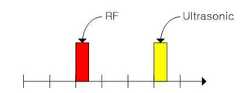
도 4는 직접 수신된 초음파 신호와 장애물에 의하여 반사된 초음파 신호가 리스너로 수신되는 과정을 시간축을 기준으로 설명하는 도면이다.
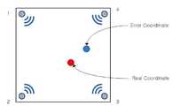
도 5는 리스너에는 반사된 초음파 신호로 인하여 원하지 않는 에러 좌표가 표시되는 상황을 설명하는 도면이다.
도 6과 도 7은 본 발명에 따른 360°전방위 송신 가능한 비콘의 전면 및 후면의 실제 제품 사진이다.
도 8은 본 발명에서 제안하는 리스너의 기능 블록도이다.1A is a view for explaining the arrangement of a conventional indoor positioning system.
1B is a functional block diagram of a beacon of a conventional indoor positioning system.
2 is a view for explaining a method of obtaining a distance from a beacon using an RF signal and an ultrasonic signal using a beacon and a listener according to the present invention.
3 is a view for explaining a situation in which an ultrasonic wave is reflected by an obstacle.
FIG. 4 is a diagram illustrating a process of receiving a directly received ultrasonic signal and an ultrasonic signal reflected by an obstacle to a listener based on a time axis.
FIG. 5 is a view for explaining a situation where undesired error coordinates are displayed on the listener due to reflected ultrasonic signals. FIG.
FIGS. 6 and 7 are photographs of actual products on the front and back sides of a 360 ° omni-directional transmittable beacon according to the present invention.
8 is a functional block diagram of a listener proposed by the present invention.
이하에서는 본 발명에 따른 실내측위시스템에 대해 첨부되는 도면과 함께 상세하게 설명하도록 한다.Hereinafter, an indoor positioning system according to the present invention will be described in detail with reference to the accompanying drawings.
도 2는 본 발명에 따른 비컨과 리스너를 이용하여 RF 신호와 초음파 신호를 이용하여 비콘과의 거리를 구하는 방법을 설명하는 도면이다.2 is a view for explaining a method of obtaining a distance from a beacon using an RF signal and an ultrasonic signal using a beacon and a listener according to the present invention.
도시된 바와 같이, 배경 기술에서 설명한 바와 같이, 전파는 빛의 속도와 같고, 음파는 공기중에서 약 (331.5+06t)m/s(t = 섭씨 온도)이므로, 근거리(10m 이내)에서 빛의 속도를 무시한다면, 비콘과 리스너간의 거리는 초음파의 도달 시간에 의해 결정될 것이다.As shown in the background, the wave is equal to the speed of light, and the sound wave is about 331.5 + 06t m / s (t = Celsius temperature) in the air, The distance between the beacon and the listener will be determined by the arrival time of the ultrasonic waves.
그런데, 음파는 벽이나, 기둥 등 장애물에 의해 반사되는 특성이 있는데, 도 3은 초음파가 장애물에 의하여 반사되는 상황을 설명하는 도면이다.However, sound waves are reflected by obstacles such as walls and pillars, and Fig. 3 is a view for explaining a situation where ultrasonic waves are reflected by obstacles.
도 3에 도시된 바와 같이, 비콘(Beacon)은 초음파 신호를 방사하며, 리스너(Listener)는 초음파 신호를 이용해 비콘과의 거리를 구해야 한다.As shown in FIG. 3, a beacon radiates an ultrasound signal, and a listener must determine the distance from the beacon using an ultrasound signal.
하지만 리스너는 비콘의 초음파 신호를 직접 받을 수도 있지만 장애물에 의해 반사된 신호도 받을 수 있다.But the listener can receive the beacon's ultrasound signal directly, but it can also receive the reflected signal from the obstacle.
도 4는 직접 수신된 초음파 신호와 장애물에 의하여 반사된 초음파 신호가 리스너로 수신되는 과정을 시간축을 기준으로 설명하는 도면이다.FIG. 4 is a diagram illustrating a process of receiving a directly received ultrasonic signal and an ultrasonic signal reflected by an obstacle to a listener based on a time axis.
도 4에서 알 수 있듯이, 반사되어 수신되는 초음파 신호는 반사되지 않고 직접 전달되는 초음파 신호보다 늦게 들어오게 되기 때문에 큰 문제가 되지 않을 수 있다.As shown in FIG. 4, the reflected ultrasonic signal received later than the ultrasonic signal transmitted directly without reflection is not a big problem.
그러나, 리스너의 수신 측 초음파 센서의 수신 각도 문제 또는 장애물에 의해 반사된 초음파 신호만을 수신하는 경우, 비콘과의 거리를 정확하게 계산하지 못해, 정상적으로 실내 위치를 표시하지 못한다는 문제점이 초래될 수 있다.However, in the case of receiving only the ultrasonic signal reflected by the reception angle problem of the receiving ultrasonic sensor of the listener or the obstacle, the distance between the ultrasonic signal and the beacon can not be accurately calculated, so that the indoor position can not be normally displayed.
이러한 경우, 도 5에 도시된 바와 같이, 리스너에는 반사된 초음파 신호로 인하여 원하지 않는 에러 좌표가 표시될 수 있을 것이다.In this case, as shown in FIG. 5, undesired error coordinates may be displayed on the listener due to the reflected ultrasonic signal.
이에 본 발명에서는 이러한 문제점을 해소할 수 있는 비콘과 리스너를 제공하고자 한다.Accordingly, the present invention provides a beacon and a listener that can solve such a problem.
먼저, 본 발명에서는 실내의 서로 다른 위치에 배치되어 RF 신호와 초음파 신호를 동시에 출력하는 비콘으로서 리스너와의 신호 수수시 음영 지역을 제거하기 위하여 비콘을 중심으로 360°전방위 송신 가능한 비콘을 제안한다.First, in the present invention, a beacon which is disposed at different positions in a room and outputs beacons simultaneously outputting an RF signal and an ultrasonic signal, and a beacon capable of transmitting a 360-degree omni-directional beacon around the beacon in order to remove a shadow area when receiving a signal with a listener.
도 6과 도 7은 본 발명에 따른 360°전방위 송신 가능한 비콘의 전면 및 후면의 실제 제품 사진이다.FIGS. 6 and 7 are photographs of actual products on the front and back sides of a 360 ° omni-directional transmittable beacon according to the present invention.
도시된 바와 같이, 본 발명에서는 초음파 신호를 출력하는 초음파 송신유닛이 기판의 동일 평면 상에서 방사상 대칭으로 6개 배치되어 있음을 알 수 있다.As shown in the figure, in the present invention, six ultrasonic transmission units for outputting ultrasonic signals are arranged radially symmetrically on the same plane of the substrate.
참고로, 본 발명에서 제안하는 비콘의 경우 기본적인 6개의 초음파 송신유닛을 구비한다는 것을 제외하고는 일반적인 비콘의 구성을 모두 포함한다.For reference, the beacon proposed in the present invention includes all the conventional beacon configurations, except that it includes six basic ultrasonic transmission units.
예컨대, 본 발명의 비콘의 고유의 식별 정보 및 좌표 정보가 포함된 RF 신호를 송신하는 RF 송신유닛과, 초음파 신호를 송신하는 초음파 송신유닛, 상기 RF 송신유닛과 상기 초음파 송신유닛을 통해 정해진 순서에 따라 동시에 RF 신호 및 초음파 신호를 각각 송신하도록 하는 비콘제어유닛을 포함하며, 상기 초음파 신호를 출력하는 상기 초음파 송신유닛이 동일 평면 상에서 방사상 대칭으로 6개 배치되어 구성된다.For example, an RF transmitting unit for transmitting an RF signal including identification information and coordinate information inherent to the beacon of the present invention, an ultrasonic transmitting unit for transmitting ultrasonic signals, an ultrasonic transmitting unit for transmitting ultrasonic signals, And a beacon control unit for simultaneously transmitting an RF signal and an ultrasonic signal, and the ultrasonic transmission units for outputting the ultrasonic signals are arranged in six radial symmetry on the same plane.
다음, 도 8은 본 발명에서 제안하는 리스너의 기능 블록도이다. 참고로, 비콘의 기본 기능 블록은 도 1b와 동일할 수 있다.8 is a functional block diagram of a listener proposed by the present invention. For reference, the basic functional block of the beacon may be the same as that of FIG. 1B.
도 8에 도시된 바와 같이, 한편 리스너(20)는 객체에 부착되어 적어도 3개 이상의 비콘(10)으로부터 각각 RF 신호와 초음파 신호를 수신하여 삼각측량법에 의해 객체의 위치 정보를 산출하는 기능을 수행한다.8, on the other hand, the
이러한 리스너(20)는 적어도 3개 이상의 비콘(10)으로부터 RF 신호를 수신하는 RF 수신유닛(21)과, 적어도 3개 이상의 비콘(10)으로부터 초음파 신호를 수신하는 초음파 수신유닛(22)과, RF 수신유닛(21)에 RF 신호가 수신시 이를 시작으로 하여 일정 시간 내에 초음파 수신유닛(22)에 초음파 신호가 수신되는 시간을 측정하는 타이머유닛(23)과, RF 수신유닛(21), 초음파 수신유닛(22) 및 타이머유닛(23)으로부터 각각 수신 정보를 전달받아 삼각측량법에 의해 리스너(20)의 현재 위치 정보를 산출하는 제어유닛(24) 및 제어유닛(24)으로부터 산출되는 리스너(20)의 위치 정보를 외부단말기로 송신하는 통신유닛(25)으로 이루어질 수 있다.The
한편 타이머유닛(23)는 RF 신호 수신시로부터 초음파 수신시까지의 시간 정보를 생성하기 위해 마련되는데, 다수 비콘(10)이 순차적으로 송출하는 초음파 신호들과의 선별을 위해 특정 비콘(10)의 RF 신호 수신시로부터 일정 시간, 예를 들면 0.001초 내지 0.1초 내에 수신되는 초음파 신호만을 해당 비콘(10)의 초음파 신호로 특정하는 구성이 필요할 것이다.On the other hand, the timer unit 23 is provided for generating time information from when the RF signal is received to when the ultrasonic wave is received. In order to discriminate the ultrasound signals from the beacon signals sequentially transmitted by the plurality of
이에 따라 타이머유닛(23)은 각 비콘(10)별 초음파 신호의 수신 시간 정보를 생성하여 이를 제어유닛(24)에 전달한다.Accordingly, the timer unit 23 generates the reception time information of the ultrasonic signal for each
상기 제어유닛(24)는 상기 RF 수신유닛(21), 초음파 수신유닛(22) 및 타이머유닛(23)으로부터 각각 수신 정보를 전달받아 각 비콘(10)과 리스너(20) 간의 거리 정보를 산출하고 3개 이상의 비콘(10)과 리스너(20) 거리정보가 산출되면 이를 통해 삼각측량법에 의해 리스너(20)의 현재 위치 정보를 산출하도록 구비된다.The
제어유닛(24)은 RF 수신유닛(21)으로부터 RF 신호가 수신되는지 여부를 확인하여 수신되는 경우 RF 수신유닛(21)으로부터 RF 신호를 전달받는 제1제어부(241)와, 상기 제1제어부(241)로부터 RF 신호를 전달받으며 초음파 수신유닛(22) 및 타이머유닛(23)으로부터 각각 수신정보를 전달받아 각 비콘(10)과의 거리 산출과 삼각측량법에 의해 리스너의 위치 정보를 산출하는 제2제어부(242)로 이루어질 수 있다. 참고로, 제1제어부(241) 및 제2제어부(242)는 필요에 따라 하나의 제어부에서 이를 통합 프로세싱하도록 구성할 수도 있게 되어 있다.The
초음파 수신유닛(22)은 초음파 신호를 수신하는 초음파센서부(221)와, 초음파센서부(221)로부터 수신되는 초음파 신호를 증폭하는 증폭부(222)와, 증폭부(222)로부터 증폭된 초음파 신호의 특정 주파수 이상의 고주파 성분을 제거하는 고주파제거부(223) 및 고주파제거부(223)로부터 고주파 성분이 제거된 초음파 신호를 디지털 신호로 변환하는 비교부(224)를 포함하여 구성될 수도 있다.The ultrasonic receiving unit 22 includes an
본 발명에 따른 실내측위시스템(100)의 가장 큰 특징 중 하나가 이러한 초음파 수신유닛(22)의 반사파 감쇠 구성에 있는데, 상기 증폭부(222)를 통해 증폭된 초음파 신호 중에 포함된 반사 초음파 신호는 대부분 고주파 성분 제거에 의해 감쇠되게 된다.One of the greatest features of the
아울러 비교부(224)를 통해서도 일정 레벨 이상의 출력값만 디지털 신호 변환시 출력됨에 따라 감쇠된 반사파가 제거되는 효과가 유도된다.Also, through the
이에 따라 반사파에 의한 위치 정보 산출값의 신뢰도 저하를 최소화할 수 있다.Accordingly, it is possible to minimize the reliability degradation of the position information calculation value due to the reflected wave.
한편, 제2제어부(242)가 타이머유닛(23)으로부터 초음파 수신 시간 정보를 통해 거리 산출을 하는 방법에 대해 간략히 설명하면 다음과 같다.A method of calculating the distance from the timer unit 23 through the ultrasonic reception time information will be briefly described as follows.
리스너(20)와 비콘(10) 사이의 거리를 추정하는데 있어In estimating the distance between the
거리 = 속도 × 시간Distance = speed × time
으로 리스너(20)와 비콘(10) 사이의 거리를 추정한다.The distance between the
여기에서, 시간은 RF 신호와 초음파 신호의 도착 시간 차이를 의미한다.Here, the time means the arrival time difference between the RF signal and the ultrasonic signal.
RF 신호의 속도는 3 x 10⁸ m/s 인데 비해서 초음파의 속도는 대략 344 m/s로 RF 신호가 초음파에 비해 훨씬 빠른 속력을 가지고 있으므로 상기 리스너(20)와 비콘(10) 사이의 도착시간 차이는 아래의 수학식 1을 사용하여 산출한다.Since the speed of the RF signal is 3 x 10⁸ m / s, the speed of the ultrasonic wave is about 344 m / s, and the RF signal has a much faster speed than that of the ultrasonic wave. Therefore, the arrival time between the
[수학식1][Equation 1]
도착시간의 차이= (거리/초음파 속도)×(거리/RF신호의 속도)Difference in arrival time = (distance / ultrasonic velocity) x (distance / velocity of RF signal)
여기서, 거리는 리스너와 비콘 사이의 거리를 나타낸다.Here, the distance represents the distance between the listener and the beacon.
RF 신호의 속력은 3 x 10⁸ m/s로서 수학식 1에서 거리/RF 신호의 속도 값은 무시할 수 있는 정도의 충분히 작은 값이므로, 추정하고자 하는 리스너와 비콘 사이의 거리는 하기의 수학식 2에 의해 계산할 수 있다.Since the velocity of the RF signal is 3 x 10⁸ m / s and the velocity value of the distance / RF signal in Equation (1) is sufficiently small to negligible, the distance between the listener and the beacon to be estimated is expressed by the following equation .
[수학식2]&Quot; (2) "
거리 = 도착시간의 차이 × 초음파의 속도Distance = difference in arrival time × speed of ultrasonic wave
따라서 상기 수학식 2에 의해 각 리스너(20)와 비콘(10) 간의 거리 정보가 산출되게 되며, 이러한 거리 정보가 적어도 3개 이상 산출되면 제2제어부(242)는 삼각측량법에 의해 리스너(20)의 위치 정보를 산출할 수 있다.Therefore, the distance information between each of the
즉, 비콘(10)이 고정된 위치에 배치되므로 삼각측량법에 따라 3개의 비콘(10)과 리스너(20) 간 거리에 의해 해당 거리값 만큼의 반경을 가지는 세 개의 원이 생성되며 이들의 교차점이 리스너(20)의 위치 정보가 된다.That is, since the
아울러 제2제어부(242)는 산출된 리스너(20)의 위치 정보를 별도의 디스플레이 수단을 통해 리스너(20)를 부착하는 사용자에게 제공하거나 통신유닛(25)을 통해 원격에 위치되는 외부단말기로 위치 정보를 송신할 수 있다.The
여기서 통신유닛(25)는 블루투스 방식으로 전송함이 바람직하다.Here, it is preferable that the
다음, 본 발명에서 제안하는 리스너의 기능에 대하여 설명하기로 한다. 참고로, 본 발명에 따른 비콘 및 리스너를 아용한 실내 위치 추적 방법에서는 하드웨어적인 필터링과, 소프트웨어적 알고리즘을 이용해 실내 위치 추적의 신뢰도를 개선시키고자 하였으며 그 방법은 다음과 같다.Next, functions of the listener proposed by the present invention will be described. For reference, in the indoor location tracking method using the beacon and the listener according to the present invention, the reliability of indoor location tracking is improved using hardware filtering and software algorithm.
먼저, 실내의 서로 다른 위치에 배치되는 적어도 3 개 이상의 비콘으로부터 일정 시간 간격으로 정해진 순서에 따라 순차적으로 각각 송신되는 RF 신호와 초음파 신호를 수신하여 삼각측량법에 의해 위치 정보를 산출하는 본 발명의 리스너는 상기 적어도 3개 이상의 비콘으로부터 RF 신호를 수신하는 RF 수신유닛과, 상기 적어도 3개 이상의 비콘으로부터 초음파 신호를 수신하는 초음파 수신유닛과, 상기 RF 수신유닛에 RF 신호가 수신시 이를 시작으로 하여 일정 시간 내에 상기 초음파 수신유닛으로 초음파 신호가 수신되는 시간을 측정하는 타이머유닛, 상기 RF 수신유닛, 초음파 수신유닛 및 타이머유닛으로부터 각각 수신 정보를 전달받아 삼각측량법에 의해 리스너의 현재 위치 정보를 산출하는 제어유닛, 제어유닛으로부터 산출되는 리스너의 위치 정보를 외부단말기로 송신하는 통신유닛을 포함한다.First, a listener of the present invention receives RF signals and ultrasonic signals sequentially transmitted from the at least three beacons located at different positions in the room in a predetermined order at predetermined time intervals, and calculates position information by triangulation. An RF receiving unit for receiving RF signals from the at least three beacons; an ultrasonic receiving unit for receiving ultrasonic signals from the at least three or more beacons; A timer unit for measuring a time at which the ultrasonic signal is received by the ultrasonic reception unit within a predetermined time, a control unit for receiving the reception information from the RF reception unit, the ultrasonic reception unit and the timer unit and calculating the current position information of the listener by triangulation Unit, the position of the listener calculated from the control unit And a communication unit for transmitting the beam to an external terminal.
한편, 본 발명에서 사용된 리스너에는 2개의 초음파 수신유닛을 탑재하였으며, 이들의 초음파 수신각도는 상호 중첩되지 않도록 배치하였다. 이는 비콘과 이스너간의 음영 지역을 최소화시키기 위함이다.In the meantime, the listener used in the present invention is equipped with two ultrasonic receiving units, and the ultrasonic receiving angles are arranged so as not to overlap each other. This is to minimize the shaded area between beacon and Isner.
일반적으로 초음파 수신유닛의 수신각도가 대략 60도 전후이므로 본 발명의 경우 120 전후의 수신각을 유지할 수 있으며 그 결과 음영 지역을 최소화시킬 수 있기 때문에 실내 위치 측정의 오차를 상당 부분 감소시킬 수 있는 이점이 있다.In general, since the receiving angle of the ultrasonic receiving unit is about 60 degrees, it is possible to maintain the receiving angle of about 120 in the present invention, and as a result, the shadow area can be minimized, .
참고로, 본 발명에 따르 초음파 수신유닛은 수신되는 초음파 신호를 증폭하는 증폭부와, 상기 증폭부로부터 증폭된 초음파 신호 중에서 특정 주파수 이상의 고주파 성분을 제거하는 고주파제거부, 및 상기 고주파제거부에서 고주파 성분이 제거된 신호를 소정 레벨의 기준 신호와 비교하여 소정치의 디지털 펄스 신호로 변환하여 출력하는 비교부를 포함한다.For example, the ultrasonic wave receiving unit according to the present invention includes an amplifying unit for amplifying a received ultrasonic signal, a high frequency removing unit for removing a high frequency component of a specific frequency or more from the ultrasonic wave signals amplified from the amplifying unit, And a comparator for comparing the signal from which the component is removed with a reference signal of a predetermined level to convert the signal into a digital pulse signal of a predetermined value and outputting the digital pulse signal.
그리고 본 발명의 제어 유닛은 상기 RF 수신유닛을 통하여 순차적으로 전송받는 RF 신호와 상기 초음파 수신유닛으로부터 전송받은 상기 디지털 펄스 신호를 수신하여 해당 비콘의 ID, X좌표, Y 좌표 및 해당 비콘과의 거리를 산출하여 저장한 후 삼각측량법에 의하여 현재 위치 좌표를 산출하는 기능을 수행한다.The control unit of the present invention receives an RF signal sequentially transmitted through the RF receiving unit and the digital pulse signal transmitted from the ultrasonic receiving unit, and outputs the ID, X coordinate, Y coordinate, and the distance between the beacon And then calculates the current position coordinates by the triangulation method.
본 발명에 있어서, 리스너에 표시되는 현재 위치 좌표는 상기 디지털 펄스 신호를 이용하여 산출한 상기 해당 비콘과의 거리가 최소 거리보다 크고 최대 거리보다 작으며 상기 해당 비콘의 ID 중복 여부를 체크하여 저장하는 과정을 3회 실시하여 산출하는 방식을 취한다.In the present invention, the current position coordinates displayed on the listener are checked by checking whether the distance between the beacon calculated using the digital pulse signal is larger than the minimum distance and smaller than the maximum distance, and whether the ID of the corresponding beacon is duplicated The process is carried out three times and calculated.
한편, 본 발명에서, 리스너에 의하여 산출된 현재 위치 좌표가 해당 비콘들에 의하여 구획되는 좌표 영역을 벗어나는 경우 상기 제어유닛은 직전 좌표를 현재 위치 좌표로 표시하여 측위 오차를 감소시키고자 하였다.Meanwhile, in the present invention, when the current position coordinates calculated by the listener deviate from the coordinate area defined by the beacons, the control unit attempts to reduce the positioning error by displaying the previous coordinates as the current position coordinates.
이하에서는 본 발명에 따른 리스너의 구체적인 기능에 대하여 설명하기로 한다.Hereinafter, specific functions of the listener according to the present invention will be described.
본 발명에 따른 리스너의 위치 정보 산출 방법은 다음과 같은 과정으로 이루어진다.The method for calculating the position information of the listener according to the present invention comprises the following steps.
먼저, 복수개의 비콘을 매트릭스 타입으로 배치한다.First, a plurality of beacons are arranged in a matrix type.
매트릭스 타입으로 배치되어 있는 비콘에 있어서 대각선 방향으로 대칭적으로 배치되어 있는 비컨간 거리를 본 발명에서는 최대 거리라고 하기로 한다.The beacon distance symmetrically arranged in a diagonal direction in a beacon arranged in a matrix type is referred to as a maximum distance in the present invention.
예컨대, 한변의 길이가 a이고 정사각형 구조로 배치된 경우 최대거리는 약 1.414a가 될 것이다.For example, if the length of one side is a and is arranged in a square structure, the maximum distance will be about 1.414a.
다음, 매트릭스 타입으로 배치되어 있는 적어도 3 개 이상의 비콘은 RF 신호와 초음파 신호를 소정의 시간차를 두고서 순차적으로 송출한다.Next, at least three or more beacons arranged in a matrix type sequentially transmit the RF signal and the ultrasonic signal with a predetermined time difference.
리스너에서는 이를 수신한 후 다음과 과정을 수행한다.After receiving it, the listener performs the following steps.
수신된 거리가 최소 거리보다 큰지 여부를 판단한다. 여기서 최소 거리란 비콘과 리스너간 최근접 거리로 통상 수cm 이상이다.And determines whether the received distance is larger than the minimum distance. The minimum distance is the closest distance between the beacon and the listener, usually a few cm or more.
다음, 수신된 거리가 최대 거리보다 작은지 여부를 판단한다. 만약 수신된 거리가 최대 거리 이상인 경우에는 해당 정보는 무시하고 처음으로 돌아간다.Next, it is determined whether or not the received distance is smaller than the maximum distance. If the received distance is greater than the maximum distance, the information is ignored and returned to the beginning.
다음, 리스너는 최소 거리 이상이고 최대 거리 이상으로 판단된 소정 거리에 대한 비콘의 ID가 중복인지 여부를 판정하고 해당 거리 정보와 ID를 저장한다. Next, the listener determines whether or not the IDs of the beacons with respect to the predetermined distances that are equal to or larger than the minimum distance and equal to or larger than the maximum distance are duplicated, and stores the distance information and the IDs.
다음, 위의 과정을 추가로 2회 이상 반복하여 삼각 측량법에 의한 위치 산출을 수행한다.Next, the above process is repeated two or more times to perform the position calculation by the triangulation method.
다음, 이렇게 산출된 리스너의 현재 위치 좌표의 X좌표가 3개 비콘의 최소 X좌표 및 촤대 X좌표 사이에 위치하는지 여부, 그리고 리스너의 현재 위치 좌표의 Y좌표가 3개 비콘의 최소 X좌표 및 촤대 X좌표 사이에 위치하는지 여부를 판정하여 상기 범위내에 각각 속하는 경우 이를 현재의 위치 좌표로 표시하고, 그렇지 않은 경우 직전 좌표를 표시함으로써 오차를 줄이고자 하였다.Next, it is determined whether or not the X coordinate of the current position coordinate of the listener is located between the minimum X coordinate and the lattice X coordinate of the three beacons, and if the Y coordinate of the current position coordinate of the listener is the minimum X coordinate of the three beacons, X coordinate, and if it belongs to each of the ranges, it is indicated by the current position coordinates, otherwise, the previous coordinates are displayed to reduce the error.
이상, 본 발명의 구체적인 실시예를 설명하였으나, 본 발명은 이 명세서에 개시된 실시예 및 첨부된 도면에 의하여 한정되지 않으며 본 발명의 기술적 사상을 벗어나지 않는 범위 이내에서 당업자에 의하여 다양하게 변형될 수 있다.While the present invention has been described in connection with what is presently considered to be practical exemplary embodiments, it is to be understood that the invention is not limited to the disclosed embodiments, but, on the contrary, is intended to cover various modifications and equivalent arrangements included within the spirit and scope of the appended claims. .
Claims (5)
Translated fromKorean실내의 서로 다른 위치에 배치되는 적어도 3개 이상의 비콘으로부터 일정 시간 간격으로 정해진 순서에 따라 순차적으로 각각 송신되는 RF 신호와 초음파 신호를 수신하여 삼각측량법에 의해 위치 정보를 산출하는 리스너는
상기 적어도 3개 이상의 비콘으로부터 RF 신호를 수신하는 RF 수신유닛과,
상기 적어도 3개 이상의 비콘으로부터 초음파 신호를 수신하는 초음파 수신 유닛과,
상기 RF 수신유닛에 RF 신호가 수신시 이를 시작으로 하여 일정 시간 내에 상기 초음파 수신유닛으로 초음파 신호가 수신되는 시간을 측정하는 타이머유닛,
상기 RF 수신유닛, 초음파 수신유닛 및 타이머유닛으로부터 각각 수신 정보를 전달받아 삼각측량법에 의해 리스너의 현재 위치 정보를 산출하는 제어유닛,
제어유닛으로부터 산출되는 리스너의 위치 정보를 외부단말기로 송신하는 통신유닛을 포함하며,
상기 초음파 수신유닛은 수신되는 초음파 신호를 증폭하는 증폭부와, 상기 증폭부로부터 증폭된 초음파 신호 중에서 특정 주파수 이상의 고주파 성분을 제거하는 고주파제거부 및 상기 고주파제거부에서 고주파 성분이 제거된 신호를 디지털 신호로 변환하되 소정 레벨의 기준 신호와 비교하여 소정 레벨이상 출력값만 디지털 펄스 신호로 변환하여 출력하는 비교부를 포함하며,
상기 제어유닛은 상기 RF 수신유닛을 통하여 순차적으로 전송받는 RF 신호와 상기 초음파 수신유닛으로부터 전송받은 상기 디지털 펄스 신호를 수신하여 해당 비콘의 ID, X좌표, Y 좌표 및 해당 비콘과의 거리를 산출하여 저장한 후 삼각측량법에 의하여 현재 위치 좌표를 산출하며,
상기 현재 위치 좌표는 상기 디지털 펄스 신호를 이용하여 산출한 상기 해당 비콘과 리스너간의 거리가 상기 비콘과 리스너간의 최소 거리보다 크고 최대 거리보다 작으며 상기 해당 비콘의 ID 중복 여부를 체크하여 저장하는 과정을 복수회 실시하여 산출하는 것을 특징으로 하는 실내 측위 시스템용 비콘 및 리스너 장치.A beacon and listener device for an indoor positioning system,
The listener for receiving the RF signal and the ultrasonic signal sequentially transmitted from the at least three beacons arranged at different positions in the room in a predetermined order at predetermined time intervals and calculating the position information by the triangulation method
An RF receiving unit for receiving an RF signal from the at least three beacons;
An ultrasonic receiving unit for receiving ultrasonic signals from at least three or more beacons;
A timer unit for measuring a time at which the ultrasonic signal is received by the ultrasonic reception unit within a predetermined time from when the RF signal is received to the RF receiving unit,
A control unit that receives reception information from the RF receiving unit, the ultrasonic receiving unit, and the timer unit and calculates current position information of the listener by triangulation,
And a communication unit for transmitting the position information of the listener calculated from the control unit to the external terminal,
The ultrasonic receiving unit includes an amplifying unit for amplifying a received ultrasonic signal, a high frequency removing unit for removing a high frequency component of a specific frequency or more from the ultrasonic wave signals amplified from the amplifying unit, And a comparator for comparing the output signal with a reference signal of a predetermined level and converting the output signal into a digital pulse signal at a predetermined level or higher,
The control unit receives the RF signal sequentially received through the RF receiving unit and the digital pulse signal transmitted from the ultrasonic receiving unit and calculates the distance between the beacon ID, the X coordinate, the Y coordinate, and the beacon After storing, the current position coordinates are calculated by triangulation method,
Wherein the current location coordinates are calculated by checking whether the distance between the corresponding beacon and the listener calculated using the digital pulse signal is greater than a minimum distance between the beacon and the listener and smaller than a maximum distance and duplicating the ID of the corresponding beacon, The beacon and the listener device for indoor positioning system.
상기 비콘 각각은
고유의 식별 정보 및 좌표 정보가 포함된 RF 신호를 송신하는 RF송신유닛과,
초음파 신호를 송신하는 초음파 송신유닛,
상기 RF 송신유닛과 상기 초음파 송신유닛을 통해 정해진 순서에 따라 동시에 RF 신호 및 초음파 신호를 각각 송신하도록 하는 비콘제어유닛을 포함하며,
상기 초음파 신호를 출력하는 상기 초음파 송신유닛이 동일 평면 상에서 방사상 대칭으로 6개 배치되어 있으며, 6개의 상기 초음파 송신유닛에서 동시에 송출되는 상기 초음파 신호는 상기 비콘을 중심으로 360°전범위로 송신되는 것을 특징으로 하는 실내 측위 시스템용 비콘 및 리스너 장치.The method according to claim 1,
Each of the beacons
An RF transmitting unit for transmitting an RF signal including unique identification information and coordinate information;
An ultrasonic transmission unit for transmitting an ultrasonic signal,
And a beacon control unit for transmitting an RF signal and an ultrasonic signal at the same time in a predetermined order through the RF transmitting unit and the ultrasonic transmitting unit,
Six ultrasonic transmission units for outputting the ultrasonic signals are arranged radially symmetrically on the same plane, and the ultrasonic signals simultaneously transmitted from the six ultrasonic transmission units are transmitted on 360 beacons around the beacon And a beacon and a listener device for an indoor positioning system.
상기 초음파 수신유닛은 초음파 수신각도가 상호 중첩되지 않도록 배치되는 2개의 초음파 센서부를 구비하는 것을 특징으로 하는 실내 측위 시스템용 비콘 및 리스너 장치.The method of claim 1, wherein
Wherein the ultrasonic receiving unit comprises two ultrasonic sensor units arranged so that ultrasonic receiving angles do not overlap with each other.
상기 현재 위치 좌표가
상기 비콘 각각에 의하여 구획되는 좌표 영역을 벗어나는 경우 상기 제어유닛은 직전 좌표를 현재 위치 좌표로 표시하는 것을 특징으로 하는 실내 측위 시스템용 비콘 및 리스너 장치.The method according to claim 1,
If the current position coordinate is
Wherein the control unit displays the previous coordinates in the current position coordinates when the beacon is out of the coordinate area defined by each of the beacons.
Priority Applications (2)
| Application Number | Priority Date | Filing Date | Title |
|---|---|---|---|
| KR1020140100096AKR101537742B1 (en) | 2014-08-04 | 2014-08-04 | Beacon and Listner for Indoor Positioning System |
| PCT/KR2015/008064WO2016021887A1 (en) | 2014-08-04 | 2015-07-31 | Beacon and listener for indoor positioning system |
Applications Claiming Priority (1)
| Application Number | Priority Date | Filing Date | Title |
|---|---|---|---|
| KR1020140100096AKR101537742B1 (en) | 2014-08-04 | 2014-08-04 | Beacon and Listner for Indoor Positioning System |
Publications (1)
| Publication Number | Publication Date |
|---|---|
| KR101537742B1true KR101537742B1 (en) | 2015-07-20 |
Family
ID=53874075
Family Applications (1)
| Application Number | Title | Priority Date | Filing Date |
|---|---|---|---|
| KR1020140100096AExpired - Fee RelatedKR101537742B1 (en) | 2014-08-04 | 2014-08-04 | Beacon and Listner for Indoor Positioning System |
Country Status (2)
| Country | Link |
|---|---|
| KR (1) | KR101537742B1 (en) |
| WO (1) | WO2016021887A1 (en) |
Cited By (7)
| Publication number | Priority date | Publication date | Assignee | Title |
|---|---|---|---|---|
| KR101705227B1 (en)* | 2015-11-06 | 2017-02-09 | 주식회사 우리엘테크 | Indoor positioning method |
| KR20170021022A (en)* | 2015-08-17 | 2017-02-27 | 울산대학교 산학협력단 | System and method for position measurement |
| KR20180082992A (en)* | 2018-07-10 | 2018-07-19 | 울산대학교 산학협력단 | System and method for position measurement |
| KR102208923B1 (en)* | 2020-11-17 | 2021-01-28 | 주식회사 자임 | Beacon signal reliability verification method and system |
| KR102247999B1 (en)* | 2020-02-14 | 2021-05-04 | 김준우 | Mobile Resource Movement Data Collecting System based on Indoor Positioning Technology, and Method thereof |
| KR20220169267A (en) | 2021-06-18 | 2022-12-27 | 주식회사 다바 | System for monitering occupant and guiding evacuation route and method thereof |
| KR20230020484A (en)* | 2015-11-23 | 2023-02-10 | 주식회사 슈프리마 | Method and system for managing a door entry using beacon signal |
Families Citing this family (1)
| Publication number | Priority date | Publication date | Assignee | Title |
|---|---|---|---|---|
| CN110335001B (en)* | 2019-08-08 | 2024-04-02 | 重庆邮电大学 | Express delivery piece positioning and guiding system and method |
Citations (4)
| Publication number | Priority date | Publication date | Assignee | Title |
|---|---|---|---|---|
| JP2002215316A (en)* | 2000-11-17 | 2002-08-02 | Fujitsu Ltd | Coordinate input device |
| KR100673484B1 (en)* | 2004-12-08 | 2007-01-24 | 한국전자통신연구원 | Position measuring device, position measuring system using same and method thereof |
| KR20100008158A (en)* | 2008-07-15 | 2010-01-25 | (주)에이스안테나 | System and method for managing location of inventor based on ir-uwb |
| KR20100088400A (en)* | 2009-01-30 | 2010-08-09 | (주)하기소닉 | Localization method of mobile robots using ultrasonic sensors and device thereby |
Family Cites Families (3)
| Publication number | Priority date | Publication date | Assignee | Title |
|---|---|---|---|---|
| KR100582018B1 (en)* | 2003-06-10 | 2006-05-22 | 학교법인 한국정보통신학원 | A system and method for measuring indoor location |
| US20050235056A1 (en)* | 2004-04-19 | 2005-10-20 | Ken-Li Chen | Location system |
| KR100699083B1 (en)* | 2005-04-22 | 2007-03-27 | 주식회사 나인티시스템 | Location estimation method |
- 2014
- 2014-08-04KRKR1020140100096Apatent/KR101537742B1/ennot_activeExpired - Fee Related
- 2015
- 2015-07-31WOPCT/KR2015/008064patent/WO2016021887A1/enactiveApplication Filing
Patent Citations (4)
| Publication number | Priority date | Publication date | Assignee | Title |
|---|---|---|---|---|
| JP2002215316A (en)* | 2000-11-17 | 2002-08-02 | Fujitsu Ltd | Coordinate input device |
| KR100673484B1 (en)* | 2004-12-08 | 2007-01-24 | 한국전자통신연구원 | Position measuring device, position measuring system using same and method thereof |
| KR20100008158A (en)* | 2008-07-15 | 2010-01-25 | (주)에이스안테나 | System and method for managing location of inventor based on ir-uwb |
| KR20100088400A (en)* | 2009-01-30 | 2010-08-09 | (주)하기소닉 | Localization method of mobile robots using ultrasonic sensors and device thereby |
Cited By (11)
| Publication number | Priority date | Publication date | Assignee | Title |
|---|---|---|---|---|
| KR20170021022A (en)* | 2015-08-17 | 2017-02-27 | 울산대학교 산학협력단 | System and method for position measurement |
| KR101882845B1 (en)* | 2015-08-17 | 2018-07-30 | 울산대학교 산학협력단 | System and method for position measurement |
| US10955538B2 (en) | 2015-08-17 | 2021-03-23 | University Of Ulsan Foundation For Industry Cooperation | Positioning transmitter, receiver, and system, and method therefor |
| KR101705227B1 (en)* | 2015-11-06 | 2017-02-09 | 주식회사 우리엘테크 | Indoor positioning method |
| KR20230020484A (en)* | 2015-11-23 | 2023-02-10 | 주식회사 슈프리마 | Method and system for managing a door entry using beacon signal |
| KR102749969B1 (en) | 2015-11-23 | 2025-01-03 | 주식회사 슈프리마 | Method and system for managing a door entry using beacon signal |
| KR20180082992A (en)* | 2018-07-10 | 2018-07-19 | 울산대학교 산학협력단 | System and method for position measurement |
| KR101969676B1 (en)* | 2018-07-10 | 2019-04-16 | 울산대학교 산학협력단 | System and method for position measurement |
| KR102247999B1 (en)* | 2020-02-14 | 2021-05-04 | 김준우 | Mobile Resource Movement Data Collecting System based on Indoor Positioning Technology, and Method thereof |
| KR102208923B1 (en)* | 2020-11-17 | 2021-01-28 | 주식회사 자임 | Beacon signal reliability verification method and system |
| KR20220169267A (en) | 2021-06-18 | 2022-12-27 | 주식회사 다바 | System for monitering occupant and guiding evacuation route and method thereof |
Also Published As
| Publication number | Publication date |
|---|---|
| WO2016021887A1 (en) | 2016-02-11 |
Similar Documents
| Publication | Publication Date | Title |
|---|---|---|
| KR101537742B1 (en) | Beacon and Listner for Indoor Positioning System | |
| US11790188B2 (en) | Positioning method, positioning system, and tag | |
| KR102133105B1 (en) | 3D spatial detection system, positioning method and system | |
| US9791540B2 (en) | Self-organizing hybrid indoor location system | |
| US7796471B2 (en) | Ultrasonic in-building positioning system based on phase difference array with ranging | |
| Koyuncu et al. | A survey of indoor positioning and object locating systems | |
| AU2023202901B2 (en) | Transmitting device for use in location determination systems | |
| US7764574B2 (en) | Positioning system using ultrasonic waves and method for operating the same | |
| US12307166B2 (en) | Acoustic positioning transmitter and receiver system and method | |
| CN108449953B (en) | Method and apparatus for registering device location | |
| Rose et al. | 3D trilateration localization using RSSI in indoor environment | |
| CN115943321A (en) | Ultra-precise object positioning system and self-positioning method using the system | |
| Murakami et al. | Five degrees-of-freedom pose-estimation method for smartphones using a single acoustic anchor | |
| EP3732509B1 (en) | Location determination using acoustic-contextual data | |
| KR100699083B1 (en) | Location estimation method | |
| KR101705227B1 (en) | Indoor positioning method | |
| KR101882845B1 (en) | System and method for position measurement | |
| CN117579987A (en) | An indoor positioning system and method based on ultrasonic and Bluetooth fingerprint database | |
| Ballazhi | Wireless indoor positioning techniques | |
| US20210263531A1 (en) | Mapping and simultaneous localisation of an object in an interior environment | |
| KR102604367B1 (en) | a high definition positioning and movement capturing device for virtual reality space sevice supply containing eXtended Reality | |
| Johansson et al. | Estimation of Orientation in a Dual-Tag Ultra Wideband Indoor Positioning System | |
| KR101969676B1 (en) | System and method for position measurement | |
| Lin et al. | Position calculating and path tracking of three dimensional location system based on different wave velocities | |
| Shen et al. | A novel WiFi-based indoor localization system |
Legal Events
| Date | Code | Title | Description |
|---|---|---|---|
| PA0109 | Patent application | St.27 status event code:A-0-1-A10-A12-nap-PA0109 | |
| P11-X000 | Amendment of application requested | St.27 status event code:A-2-2-P10-P11-nap-X000 | |
| P13-X000 | Application amended | St.27 status event code:A-2-2-P10-P13-nap-X000 | |
| PA0201 | Request for examination | St.27 status event code:A-1-2-D10-D11-exm-PA0201 | |
| PA0302 | Request for accelerated examination | St.27 status event code:A-1-2-D10-D17-exm-PA0302 St.27 status event code:A-1-2-D10-D16-exm-PA0302 | |
| E902 | Notification of reason for refusal | ||
| PE0902 | Notice of grounds for rejection | St.27 status event code:A-1-2-D10-D21-exm-PE0902 | |
| E13-X000 | Pre-grant limitation requested | St.27 status event code:A-2-3-E10-E13-lim-X000 | |
| P11-X000 | Amendment of application requested | St.27 status event code:A-2-2-P10-P11-nap-X000 | |
| P13-X000 | Application amended | St.27 status event code:A-2-2-P10-P13-nap-X000 | |
| E701 | Decision to grant or registration of patent right | ||
| PE0701 | Decision of registration | St.27 status event code:A-1-2-D10-D22-exm-PE0701 | |
| GRNT | Written decision to grant | ||
| PR0701 | Registration of establishment | St.27 status event code:A-2-4-F10-F11-exm-PR0701 | |
| PR1002 | Payment of registration fee | St.27 status event code:A-2-2-U10-U11-oth-PR1002 Fee payment year number:1 | |
| PG1601 | Publication of registration | St.27 status event code:A-4-4-Q10-Q13-nap-PG1601 | |
| FPAY | Annual fee payment | Payment date:20180710 Year of fee payment:4 | |
| PR1001 | Payment of annual fee | St.27 status event code:A-4-4-U10-U11-oth-PR1001 Fee payment year number:4 | |
| FPAY | Annual fee payment | Payment date:20190709 Year of fee payment:5 | |
| PR1001 | Payment of annual fee | St.27 status event code:A-4-4-U10-U11-oth-PR1001 Fee payment year number:5 | |
| PC1903 | Unpaid annual fee | St.27 status event code:A-4-4-U10-U13-oth-PC1903 Not in force date:20200714 Payment event data comment text:Termination Category : DEFAULT_OF_REGISTRATION_FEE | |
| K11-X000 | Ip right revival requested | St.27 status event code:A-6-4-K10-K11-oth-X000 | |
| PC1903 | Unpaid annual fee | St.27 status event code:N-4-6-H10-H13-oth-PC1903 Ip right cessation event data comment text:Termination Category : DEFAULT_OF_REGISTRATION_FEE Not in force date:20200714 | |
| PR0401 | Registration of restoration | St.27 status event code:A-6-4-K10-K13-oth-PR0401 | |
| PR1001 | Payment of annual fee | St.27 status event code:A-4-4-U10-U11-oth-PR1001 Fee payment year number:6 | |
| PC1903 | Unpaid annual fee | St.27 status event code:A-4-4-U10-U13-oth-PC1903 Not in force date:20210714 Payment event data comment text:Termination Category : DEFAULT_OF_REGISTRATION_FEE | |
| K11-X000 | Ip right revival requested | St.27 status event code:A-6-4-K10-K11-oth-X000 | |
| PC1903 | Unpaid annual fee | St.27 status event code:N-4-6-H10-H13-oth-PC1903 Ip right cessation event data comment text:Termination Category : DEFAULT_OF_REGISTRATION_FEE Not in force date:20210714 | |
| PR0401 | Registration of restoration | St.27 status event code:A-6-4-K10-K13-oth-PR0401 | |
| PR1001 | Payment of annual fee | St.27 status event code:A-4-4-U10-U11-oth-PR1001 Fee payment year number:7 | |
| PC1903 | Unpaid annual fee | St.27 status event code:A-4-4-U10-U13-oth-PC1903 Not in force date:20220714 Payment event data comment text:Termination Category : DEFAULT_OF_REGISTRATION_FEE | |
| PC1903 | Unpaid annual fee | St.27 status event code:N-4-6-H10-H13-oth-PC1903 Ip right cessation event data comment text:Termination Category : DEFAULT_OF_REGISTRATION_FEE Not in force date:20220714 |