KR101537718B1 - Cutting tools having coated layer removed partly - Google Patents
Cutting tools having coated layer removed partlyDownload PDFInfo
- Publication number
- KR101537718B1 KR101537718B1KR1020140048442AKR20140048442AKR101537718B1KR 101537718 B1KR101537718 B1KR 101537718B1KR 1020140048442 AKR1020140048442 AKR 1020140048442AKR 20140048442 AKR20140048442 AKR 20140048442AKR 101537718 B1KR101537718 B1KR 101537718B1
- Authority
- KR
- South Korea
- Prior art keywords
- drill
- resistant layer
- tip
- wear
- center
- Prior art date
- Legal status (The legal status is an assumption and is not a legal conclusion. Google has not performed a legal analysis and makes no representation as to the accuracy of the status listed.)
- Active
Links
Images


Classifications
- B—PERFORMING OPERATIONS; TRANSPORTING
- B23—MACHINE TOOLS; METAL-WORKING NOT OTHERWISE PROVIDED FOR
- B23C—MILLING
- B23C5/00—Milling-cutters
- B23C5/02—Milling-cutters characterised by the shape of the cutter
- B23C5/10—Shank-type cutters, i.e. with an integral shaft
- B23C5/1009—Ball nose end mills
- B—PERFORMING OPERATIONS; TRANSPORTING
- B23—MACHINE TOOLS; METAL-WORKING NOT OTHERWISE PROVIDED FOR
- B23B—TURNING; BORING
- B23B51/00—Tools for drilling machines
- B—PERFORMING OPERATIONS; TRANSPORTING
- B23—MACHINE TOOLS; METAL-WORKING NOT OTHERWISE PROVIDED FOR
- B23C—MILLING
- B23C5/00—Milling-cutters
- B23C5/16—Milling-cutters characterised by physical features other than shape
- C—CHEMISTRY; METALLURGY
- C23—COATING METALLIC MATERIAL; COATING MATERIAL WITH METALLIC MATERIAL; CHEMICAL SURFACE TREATMENT; DIFFUSION TREATMENT OF METALLIC MATERIAL; COATING BY VACUUM EVAPORATION, BY SPUTTERING, BY ION IMPLANTATION OR BY CHEMICAL VAPOUR DEPOSITION, IN GENERAL; INHIBITING CORROSION OF METALLIC MATERIAL OR INCRUSTATION IN GENERAL
- C23C—COATING METALLIC MATERIAL; COATING MATERIAL WITH METALLIC MATERIAL; SURFACE TREATMENT OF METALLIC MATERIAL BY DIFFUSION INTO THE SURFACE, BY CHEMICAL CONVERSION OR SUBSTITUTION; COATING BY VACUUM EVAPORATION, BY SPUTTERING, BY ION IMPLANTATION OR BY CHEMICAL VAPOUR DEPOSITION, IN GENERAL
- C23C14/00—Coating by vacuum evaporation, by sputtering or by ion implantation of the coating forming material
- C23C14/06—Coating by vacuum evaporation, by sputtering or by ion implantation of the coating forming material characterised by the coating material
- C23C14/0664—Carbonitrides
- C—CHEMISTRY; METALLURGY
- C23—COATING METALLIC MATERIAL; COATING MATERIAL WITH METALLIC MATERIAL; CHEMICAL SURFACE TREATMENT; DIFFUSION TREATMENT OF METALLIC MATERIAL; COATING BY VACUUM EVAPORATION, BY SPUTTERING, BY ION IMPLANTATION OR BY CHEMICAL VAPOUR DEPOSITION, IN GENERAL; INHIBITING CORROSION OF METALLIC MATERIAL OR INCRUSTATION IN GENERAL
- C23C—COATING METALLIC MATERIAL; COATING MATERIAL WITH METALLIC MATERIAL; SURFACE TREATMENT OF METALLIC MATERIAL BY DIFFUSION INTO THE SURFACE, BY CHEMICAL CONVERSION OR SUBSTITUTION; COATING BY VACUUM EVAPORATION, BY SPUTTERING, BY ION IMPLANTATION OR BY CHEMICAL VAPOUR DEPOSITION, IN GENERAL
- C23C14/00—Coating by vacuum evaporation, by sputtering or by ion implantation of the coating forming material
- C23C14/06—Coating by vacuum evaporation, by sputtering or by ion implantation of the coating forming material characterised by the coating material
- C23C14/08—Oxides
- C23C14/081—Oxides of aluminium, magnesium or beryllium
- C—CHEMISTRY; METALLURGY
- C23—COATING METALLIC MATERIAL; COATING MATERIAL WITH METALLIC MATERIAL; CHEMICAL SURFACE TREATMENT; DIFFUSION TREATMENT OF METALLIC MATERIAL; COATING BY VACUUM EVAPORATION, BY SPUTTERING, BY ION IMPLANTATION OR BY CHEMICAL VAPOUR DEPOSITION, IN GENERAL; INHIBITING CORROSION OF METALLIC MATERIAL OR INCRUSTATION IN GENERAL
- C23C—COATING METALLIC MATERIAL; COATING MATERIAL WITH METALLIC MATERIAL; SURFACE TREATMENT OF METALLIC MATERIAL BY DIFFUSION INTO THE SURFACE, BY CHEMICAL CONVERSION OR SUBSTITUTION; COATING BY VACUUM EVAPORATION, BY SPUTTERING, BY ION IMPLANTATION OR BY CHEMICAL VAPOUR DEPOSITION, IN GENERAL
- C23C14/00—Coating by vacuum evaporation, by sputtering or by ion implantation of the coating forming material
- C23C14/22—Coating by vacuum evaporation, by sputtering or by ion implantation of the coating forming material characterised by the process of coating
- C23C14/24—Vacuum evaporation
- C23C14/32—Vacuum evaporation by explosion; by evaporation and subsequent ionisation of the vapours, e.g. ion-plating
- C23C14/325—Electric arc evaporation
- C—CHEMISTRY; METALLURGY
- C23—COATING METALLIC MATERIAL; COATING MATERIAL WITH METALLIC MATERIAL; CHEMICAL SURFACE TREATMENT; DIFFUSION TREATMENT OF METALLIC MATERIAL; COATING BY VACUUM EVAPORATION, BY SPUTTERING, BY ION IMPLANTATION OR BY CHEMICAL VAPOUR DEPOSITION, IN GENERAL; INHIBITING CORROSION OF METALLIC MATERIAL OR INCRUSTATION IN GENERAL
- C23C—COATING METALLIC MATERIAL; COATING MATERIAL WITH METALLIC MATERIAL; SURFACE TREATMENT OF METALLIC MATERIAL BY DIFFUSION INTO THE SURFACE, BY CHEMICAL CONVERSION OR SUBSTITUTION; COATING BY VACUUM EVAPORATION, BY SPUTTERING, BY ION IMPLANTATION OR BY CHEMICAL VAPOUR DEPOSITION, IN GENERAL
- C23C28/00—Coating for obtaining at least two superposed coatings either by methods not provided for in a single one of groups C23C2/00 - C23C26/00 or by combinations of methods provided for in subclasses C23C and C25C or C25D
- C23C28/04—Coating for obtaining at least two superposed coatings either by methods not provided for in a single one of groups C23C2/00 - C23C26/00 or by combinations of methods provided for in subclasses C23C and C25C or C25D only coatings of inorganic non-metallic material
- C23C28/042—Coating for obtaining at least two superposed coatings either by methods not provided for in a single one of groups C23C2/00 - C23C26/00 or by combinations of methods provided for in subclasses C23C and C25C or C25D only coatings of inorganic non-metallic material including a refractory ceramic layer, e.g. refractory metal oxides, ZrO2, rare earth oxides
- C—CHEMISTRY; METALLURGY
- C23—COATING METALLIC MATERIAL; COATING MATERIAL WITH METALLIC MATERIAL; CHEMICAL SURFACE TREATMENT; DIFFUSION TREATMENT OF METALLIC MATERIAL; COATING BY VACUUM EVAPORATION, BY SPUTTERING, BY ION IMPLANTATION OR BY CHEMICAL VAPOUR DEPOSITION, IN GENERAL; INHIBITING CORROSION OF METALLIC MATERIAL OR INCRUSTATION IN GENERAL
- C23C—COATING METALLIC MATERIAL; COATING MATERIAL WITH METALLIC MATERIAL; SURFACE TREATMENT OF METALLIC MATERIAL BY DIFFUSION INTO THE SURFACE, BY CHEMICAL CONVERSION OR SUBSTITUTION; COATING BY VACUUM EVAPORATION, BY SPUTTERING, BY ION IMPLANTATION OR BY CHEMICAL VAPOUR DEPOSITION, IN GENERAL
- C23C28/00—Coating for obtaining at least two superposed coatings either by methods not provided for in a single one of groups C23C2/00 - C23C26/00 or by combinations of methods provided for in subclasses C23C and C25C or C25D
- C23C28/04—Coating for obtaining at least two superposed coatings either by methods not provided for in a single one of groups C23C2/00 - C23C26/00 or by combinations of methods provided for in subclasses C23C and C25C or C25D only coatings of inorganic non-metallic material
- C23C28/044—Coating for obtaining at least two superposed coatings either by methods not provided for in a single one of groups C23C2/00 - C23C26/00 or by combinations of methods provided for in subclasses C23C and C25C or C25D only coatings of inorganic non-metallic material coatings specially adapted for cutting tools or wear applications
- C—CHEMISTRY; METALLURGY
- C23—COATING METALLIC MATERIAL; COATING MATERIAL WITH METALLIC MATERIAL; CHEMICAL SURFACE TREATMENT; DIFFUSION TREATMENT OF METALLIC MATERIAL; COATING BY VACUUM EVAPORATION, BY SPUTTERING, BY ION IMPLANTATION OR BY CHEMICAL VAPOUR DEPOSITION, IN GENERAL; INHIBITING CORROSION OF METALLIC MATERIAL OR INCRUSTATION IN GENERAL
- C23C—COATING METALLIC MATERIAL; COATING MATERIAL WITH METALLIC MATERIAL; SURFACE TREATMENT OF METALLIC MATERIAL BY DIFFUSION INTO THE SURFACE, BY CHEMICAL CONVERSION OR SUBSTITUTION; COATING BY VACUUM EVAPORATION, BY SPUTTERING, BY ION IMPLANTATION OR BY CHEMICAL VAPOUR DEPOSITION, IN GENERAL
- C23C30/00—Coating with metallic material characterised only by the composition of the metallic material, i.e. not characterised by the coating process
- C23C30/005—Coating with metallic material characterised only by the composition of the metallic material, i.e. not characterised by the coating process on hard metal substrates
- B—PERFORMING OPERATIONS; TRANSPORTING
- B23—MACHINE TOOLS; METAL-WORKING NOT OTHERWISE PROVIDED FOR
- B23B—TURNING; BORING
- B23B2224/00—Materials of tools or workpieces composed of a compound including a metal
- B23B2224/04—Aluminium oxide
- B—PERFORMING OPERATIONS; TRANSPORTING
- B23—MACHINE TOOLS; METAL-WORKING NOT OTHERWISE PROVIDED FOR
- B23B—TURNING; BORING
- B23B2224/00—Materials of tools or workpieces composed of a compound including a metal
- B23B2224/32—Titanium carbide nitride (TiCN)
- B—PERFORMING OPERATIONS; TRANSPORTING
- B23—MACHINE TOOLS; METAL-WORKING NOT OTHERWISE PROVIDED FOR
- B23B—TURNING; BORING
- B23B2228/00—Properties of materials of tools or workpieces, materials of tools or workpieces applied in a specific manner
- B23B2228/10—Coatings
- B—PERFORMING OPERATIONS; TRANSPORTING
- B23—MACHINE TOOLS; METAL-WORKING NOT OTHERWISE PROVIDED FOR
- B23B—TURNING; BORING
- B23B2228/00—Properties of materials of tools or workpieces, materials of tools or workpieces applied in a specific manner
- B23B2228/36—Multi-layered
- B—PERFORMING OPERATIONS; TRANSPORTING
- B23—MACHINE TOOLS; METAL-WORKING NOT OTHERWISE PROVIDED FOR
- B23C—MILLING
- B23C2224/00—Materials of tools or workpieces composed of a compound including a metal
- B23C2224/04—Aluminium oxide
- B—PERFORMING OPERATIONS; TRANSPORTING
- B23—MACHINE TOOLS; METAL-WORKING NOT OTHERWISE PROVIDED FOR
- B23C—MILLING
- B23C2224/00—Materials of tools or workpieces composed of a compound including a metal
- B23C2224/32—Titanium carbide nitride (TiCN)
- B—PERFORMING OPERATIONS; TRANSPORTING
- B23—MACHINE TOOLS; METAL-WORKING NOT OTHERWISE PROVIDED FOR
- B23C—MILLING
- B23C2228/00—Properties of materials of tools or workpieces, materials of tools or workpieces applied in a specific manner
- B23C2228/10—Coating
Landscapes
- Chemical & Material Sciences (AREA)
- Engineering & Computer Science (AREA)
- Mechanical Engineering (AREA)
- Chemical Kinetics & Catalysis (AREA)
- Materials Engineering (AREA)
- Metallurgy (AREA)
- Organic Chemistry (AREA)
- Inorganic Chemistry (AREA)
- Ceramic Engineering (AREA)
- Drilling Tools (AREA)
Abstract
Translated fromKoreanDescription
Translated fromKorean본 발명은 선단부 폴리싱을 통해 부분적으로 제거된 피막이 형성된 절삭공구에 관한 것으로, 보다 상세하게는 드릴 또는 볼 엔드밀과 같이 선단부의 중심이 피삭재에 접촉한 상태에서 회전하면서 절삭이 이루어지는 공구의 선단부에 형성된 내마모층의 일부를 상기 드릴 또는 볼엔드밀의 선단부의 중심으로부터 소정 영역까지 선택적으로 제거함으로써, 극저속 영역에서 발생하는 미소취성마모를 억제하여, 드릴 또는 볼 엔드밀과 같은 절삭공구의 절삭수명을 현저하게 개선한 절삭공구에 관한 것이다.
The present invention relates to a cutting tool having a coating partially removed through a tip polishing, and more particularly, to a cutting tool having a coating formed on a tip portion of a tool which is cut while being rotated while the center of the tip portion is in contact with the workpiece, A part of the abrasion layer is selectively removed from the center of the tip of the drill or ball end mill to a predetermined region to suppress the minute brittle wear occurring in the extremely low speed region and the cutting life of the cutting tool such as a drill or a ball end mill is remarkably reduced And an improved cutting tool.
드릴은 공작물에 원형의 홀을 가공하는데 사용되는 절삭공구로서, 강이나 초경합금과 같은 기재를 사용하여 만든 봉상의 소재에 절삭날이 외주부를 따라 나선상으로 형성되어 있고 선단부는 원추형으로 형성되어 있는 공구이다.A drill is a cutting tool used for machining a circular hole in a workpiece, in which a cutting edge is formed in a spiral shape along the outer periphery of a rod-like material made of a material such as steel or a cemented carbide and the tip portion is formed in a conical shape .
볼 엔드밀(end mill)은 드릴과 유사한 외관을 가지며, 선단이 구상으로 이루어져 있어, 주로 곡면을 절삭하는데 사용되는 공구이다.Ball end mills have a drill-like appearance and are spherical in shape and are mainly used for cutting surfaces.
이러한 드릴 또는 볼 엔드밀과 같은 공구는, 절삭가공 중에 원추형 선단부 및 구상의 선단부의 중심부가 피삭재와 접촉하며 그것을 중심으로 회전하면서 절삭가공이 이루어지는 특징이 있다.Such a tool such as a drill or a ball end mill is characterized in that a center portion of a conical tip portion and a spherical tip portion contact the workpiece during cutting, and cutting is performed while rotating around the center.
한편, 절삭수명을 향상시키기 위하여, 상기 드릴 또는 볼 엔드밀 중에서 실제 절삭이 이루어지는 부분에는 예를 들어 TiCN, TiAlN, TiAlCrN, Al2O3와 같은 경질소재로 이루어진 단층 내지는 다층의 내마모층이 형성된다.On the other hand, in order to improve cutting life, a single layer or a multi-layer wear-resistant layer made of a hard material such as TiCN, TiAlN, TiAlCrN or Al2 O3 is formed in a portion where the cutting is actually performed in the drill or ball end mill do.
그런데, 드릴과 볼 엔드밀 같은 공구를 회전시키게 되면, 피삭재와 맞닫는 선단부 및 저인은 중심 포인트를 기점으로 반지름 R 값에 비례하여 속도가 증가하기 때문에, 중심부는 피삭재와 저속으로 접하고 주변으로 갈수록 피삭재와 고속으로 접하게 된다.However, when a tool such as a drill and a ball end mill is rotated, since the speed increases in proportion to the value of the radius R from the center point of the tip end portion and the bottom end which are engaged with the workpiece, the center portion is in contact with the workpiece at low speed, And high speed.
또한 드릴과 볼 엔드밀의 중심부는 극저속으로 피삭재와 접하게 되는데, 이와 같은 극저속 영역에서는 피로(fatigue)에 의한 소위 '미소취성마모(micro-brittle wear)'가 발생하며, 특히 고이송 드릴 가공 시 높은 이송 속도에 의해 형성되는 높은 압력은 저인 중심부의 '미소취성마모(micro-brittle wear)'를 가속화시키는 작용을 하며, 이는 드릴 또는 볼 엔드밀의 공구수명을 저하시키는 주요한 원인이 된다.In addition, the central portion of the drill and the ball end mill are brought into contact with the workpiece at an extremely low speed. In such an extremely low speed region, so-called micro-brittle wear occurs due to fatigue, The high pressure created by the high feed rate acts to accelerate the micro-brittle wear of the low center, which is a major cause of the tool life of the drill or ball end mill.
한편, 내마모층이 형성되는 절삭공구에는 내마모층 상에 추가로 장식 또는 사용여부에 대한 식별의 목적으로 커버층을 형성하기도 하며, 이와 같이 커버층을 형성할 경우, 형성된 커버층은 내마모층의 손상없이 쉽게 제거되어야 하는데, 하기 특허문헌에는 내마모층과 커버층 사이에 추가로 분리층을 구비하여 커버층이 쉽게 분리되도록 하는 기술이 개시되어 있다.On the other hand, the cutting tool in which the wear resistant layer is formed may also be formed with a cover layer for the purpose of discriminating whether or not the wear resistant layer is further decorated or used. When such a cover layer is formed, The following patent document discloses a technique for easily separating the cover layer by providing a further separating layer between the wear resistant layer and the cover layer.
그런데, 이 기술은 본격적인 절삭 작업에 앞서 이루어지는 커버층의 제거 시 내마모층의 손상을 없애기 위한 것으로, 내마모층 자체를 박리하여 절삭수명을 개선한다는 개념을 제공하는 것은 아니다.
However, this technique is intended to eliminate the damage of the wear-resistant layer when the cover layer is removed prior to the full-scale cutting operation, and does not provide a concept of improving the cutting life by stripping the wear-resistant layer itself.
본 발명의 과제는 드릴 또는 엔드밀과 같은 절삭공구에서 발생하는 미소취성마모(micro-brittle wear)에 의해 발생하는 공구 수명의 저하를 막을 수 있는 절삭공구를 제공하는데 있다.
It is an object of the present invention to provide a cutting tool capable of preventing deterioration of tool life caused by micro-brittle wear occurring in a cutting tool such as a drill or an end mill.
상기 과제를 해결하기 위해 본 발명은, 기둥상으로 이루어지고 선단부의 중심이 피삭재와 접하여 회전하면서 절삭가공이 이루어지는 절삭공구로서, 상기 절삭공구의 선단부는 소결합금을 기재로 하며, 상기 선단부에는 내마모층이 형성되어 있고, 상기 선단부의 중심으로부터 0.01R~0.8R (R: 상기 기둥상 공구의 반경) 이내에 형성된 상기 내마모층의 일부 또는 전부가 제거된 절삭공구를 제공한다.
In order to solve the above-described problems, the present invention provides a cutting tool having a columnar shape, the center of the tip portion being in contact with a workpiece to rotate while being cut, the tip of the cutting tool is made of a sintered alloy as a substrate, And a part or all of the abrasion resistant layer formed within 0.01R to 0.8R (R: radius of the pillar-shaped tool) from the center of the tip end portion is removed.
본 발명은 드릴이나 볼 엔드밀과 같은 공구의 선단부에 형성된 내마모층을 중심부 기준으로 0.01R~0.8R(R: 기둥상 공구의 반경) 범위까지 선택적으로 일부분 제거함으로써, 종래 드릴과 볼 엔드밀에서 발생하는 미소취성마모(micro-brittle wear)에 의한 내마모층의 마모 및 전파를 방지하여, 드릴과 볼 엔드밀의 수명을 현저하게 향상시킬 수 있다.
In the present invention, by selectively removing a part of the abrasion-resistant layer formed at the tip of the tool such as a drill or a ball end mill to a range of 0.01R to 0.8R (R: the radius of the pillar-shaped tool) Wear and propagation of the abrasion resistant layer caused by micro-brittle wear that occurs can be prevented, and the service life of the drill and the ball end mill can be remarkably improved.
도 1은 본 발명에 따라 내마모층을 선택적으로 제거한 공구의 선단부를 개략적으로 도시한 것이다.
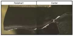
도 2는 본 발명의 실시예 1에 따라 내마모층을 부분적으로 제거한 드릴로 가공을 수행한 후, 드릴 선단부의 중심과 주변을 관찰한 사진이다.
도 3은 본 발명의 실시예 2에 따라 내마모층을 부분적으로 제거한 드릴로 가공을 수행한 후, 드릴 선단부의 중심과 주변을 관찰한 사진이다.
도 4는 비교예 1에 따른 내마모층을 형성한 드릴로 가공을 수행한 후, 드릴 선단부의 중심과 주변을 관찰한 사진이다.
도 5는 비교예 2에 따른 내마모층을 형성한 드릴로 가공을 수행한 후, 드릴 선단부의 중심과 주변을 관찰한 사진이다.
도 6은 비교예 3에 따른 내마모층을 형성한 드릴로 가공을 수행한 후, 드릴 선단부의 중심과 주변을 관찰한 사진이다.
도 7은 비교예 4에 따른 내마모층을 형성한 드릴로 가공을 수행한 후, 드릴 선단부의 중심과 주변을 관찰한 사진이다.Fig. 1 schematically shows a tip of a tool selectively removing an abrasion resistant layer according to the present invention. Fig.
FIG. 2 is a photograph showing the center and the periphery of a drill tip after drilling with a wear-resistant layer partially removed according to Embodiment 1 of the present invention. FIG.
FIG. 3 is a photograph showing the center and the periphery of the tip of the drill after the drilling with the wear-resistant layer partially removed according to the second embodiment of the present invention.
4 is a photograph showing the center and the periphery of the tip of the drill after the drilling with the wear resistant layer according to Comparative Example 1 is performed.
5 is a photograph showing the center and the periphery of the tip of the drill after the drilling with the wear resistant layer according to the comparative example 2 is performed.
Fig. 6 is a photograph showing the center and the periphery of the tip of the drill after the drilling with the wear resistant layer according to the comparative example 3 is performed.
Fig. 7 is a photograph showing the center and the periphery of the tip of the drill after the drilling with the wear resistant layer according to the comparative example 4 is performed.
이하, 첨부 도면을 참조하여 본 발명의 실시예를 상세히 설명한다. 그러나, 다음에 예시하는 본 발명의 실시예는 여러 가지 다른 형태로 변형될 수 있으며, 본 발명의 범위가 다음에 상술하는 실시예에 한정되는 것은 아니다. 본 발명의 실시예는 당 업계에서 평균적인 지식을 가진 자에게 본 발명을 보다 완전하게 설명하기 위하여 제공되는 것이다.Hereinafter, embodiments of the present invention will be described in detail with reference to the accompanying drawings. However, the following embodiments of the present invention may be modified into various other forms, and the scope of the present invention is not limited to the embodiments described below. Embodiments of the present invention are provided to more fully describe the present invention to those skilled in the art.
본 발명에 있어서 '공구 반경(R)'은 기둥상으로 이루어진 공구의 기둥부의 반경으로, 원형인 경우 그 반경, 다각형인 경우 단면상 내접원의 반경을 의미한다.In the present invention, the 'tool radius (R)' is the radius of the column portion of the tool made up of a columnar shape, the radius thereof when it is circular, and the radius of the inscribed circle when it is polygonal.
본 발명자들은 드릴과 볼 엔드밀 가공 시 중심부의 극저속 영역에서 발생하는 미소취성마모(micro-brittle wear)와 고이송 가공 시 형성되는 높은 압력으로 인해 공구 수명이 저하되는 것을 해결하기 위해 연구한 결과, 드릴의 선단 중심부의 극저속 영역을 포함하는 저인부에 형성되는 내마모층 중의 일부를, 도 1에 도시된 바와 같이, 랩핑(lapping)과 같은 공정을 통해 중심부에 반경기준으로 0.01R~0.8R(직경 기준으로 1.6R) 범위로 부분적으로 제거하는 선단부 폴리싱을 수행할 경우, 미소취성마모를 억제하여 절삭수명이 개선될 수 있음을 밝혀내고 본 발명에 이르게 되었다.The inventors of the present invention conducted studies to solve the problem that the tool life is degraded due to the micro-brittle wear occurring in the very low speed region at the central portion in the drill and ball end mill processing and the high pressure formed in the high- , A portion of the abrasion-resistant layer formed on the low-abrasive portion including the extremely low-speed region at the center of the tip of the drill is removed from the center portion by a process such as lapping, as shown in Fig. 1, R (1.6 R on a diameter basis), the cutting life can be improved by suppressing the micro-abrasion wear, leading to the present invention.
상기 내마모층은 단층으로 형성된 경우 그 일부, 다층으로 형성된 경우 다층을 구성하는 각층의 일부 또는 전부가 제거될 수 있다. 이때, 제거되는 박막의 두께는 박막이 최대로 제거되는 지점에서 내마모층의 전체 두께 대비 1%~90%의 정도로 제거되면 본 발명의 효과를 얻을 수 있으나, 박막의 제거 두께를 5%~30%로 하는 것이 바람직하다.The abrasion resistant layer may be partially removed when it is formed as a single layer, or part or all of each layer constituting the multiple layers when formed as a multilayer. At this time, if the thickness of the thin film to be removed is about 1% to 90% of the total thickness of the wear-resistant layer at the point where the thin film is maximally removed, the effect of the present invention can be obtained. However, %.
상기 내마모층의 제거 영역은 선단부를 중심으로부터 0.01R~0.8R 범위로 제거되어야 하는데, 이는 내마모층의 제거 영역이 0.8R을 초과하면 내마모성이 저하되어 절삭공구의 수명이 저하되고, 0.01R 미만으로 제거할 경우 미소취성마모를 충분히 억제하기 어렵기 때문이다. 한편, 바람직한 내마모층의 제거 범위는 0.02R~0.6R이고, 보다 바람직한 내마모층의 제거 범위는 0.02R~0.5R이다.The removal region of the wear resistant layer should be removed from the center in the range of 0.01R to 0.8R from the center. If the removal region of the wear resistant layer exceeds 0.8R, the abrasion resistance is lowered and the life of the cutting tool is lowered. It is difficult to sufficiently suppress the fine brittle abrasion. On the other hand, the preferable range of the wear resistant layer is 0.02R to 0.6R, and the preferable range of the wear resistant layer is 0.02R to 0.5R.
상기 절삭공구는 드릴 또는 볼 엔드밀일 수 있으나, 본 발명의 기술적 사상은 드릴 또는 볼 엔드밀과 유사한 절삭가공을 수행하여 동일한 기구로 내마모층의 마모 및 전파가 이루어지는 절삭공구에서 접촉 중심부를 중심으로 소정 영역을 제거하는 것을 포함한다.The cutting tool may be a drill or a ball end mill. However, the technical idea of the present invention is that a cutting tool similar to that of a drill or a ball end mill is performed so that abrasion and spreading of the wear- And removing the area.
상기 내마모층은 단층 박막 또는 다층 박막으로 이루어질 수 있으며, 상기 단층 박막 또는 다층 박막은, 주기율표의 4a, 5a, 6a족의 금속원소 및 Al과 Si중에서 선택된 1종 이상 원소를 포함하고, N, C, O 중에서 선택된 1종 이상의 비금속 원소을 포함하는 박막을 하나 이상 포함할 수 있다. 예를 들어, 상기 내마모층은 TiCN, TiAlN, TiAlCrN, 또는 Al2O3를 포함할 수 있다.The wear resistant layer may be a single layer or a multilayer thin film. The single layer thin film or the multilayer thin film may include at least one element selected from Group 4a, Group 5a, and Group 6a elements of the periodic table and Al and Si, C, and < RTI ID = 0.0 > O, < / RTI > For example, the wear-resistant layer may include TiCN, TiAlN, TiAlCrN, or Al2 O3.
이하 본 발명의 바람직한 실시예와 이의 비교예를 통해 본 발명을 보다 상세하게 설명한다.
Hereinafter, the present invention will be described in more detail with reference to preferred embodiments and comparative examples.
[실시예 1][Example 1]
10% Co를 포함하는 초경합금을 기재로 사용하여 한국야금(주)의 형번 TPD150B의 형상으로 드릴 가공을 한 후, 드릴의 표면에 물리적 기상 증착법(Physical Vapor Deposition)인 아크 이온 플레이팅법으로 TiAlCr 타겟을 사용하여 TiAlCrN 박막을 약 5㎛ 두께로 증착하여 내마모층을 형성하였다.10% Co was used as a base material and drilled in the shape of Model TPD150B of Korea Metallurgy Co., Ltd. Then, a TiAlCr target was formed on the surface of the drill by arc ion plating, physical vapor deposition (Physical Vapor Deposition) A TiAlCrN thin film was deposited to a thickness of about 5 탆 to form a wear resistant layer.
이와 같이 형성된 TiAlCrN 박막을 에어로 랩핑(aero-lapping) 장치를 이용하여, 습식미디어(다이아몬드 입자, 폴리머 입자를 포함하는 복합 연마제)를 40Hz의 압력으로 10초간 분사하는 방법을 사용하여 중심부에서 약 0.2R까지 선단부 폴리싱(polishing)을 수행하여, 도 1에 도시된 바와 같이, 내마모층이 부분적으로 제거되도록 하였다.The thus formed TiAlCrN thin film was sprayed for 10 seconds at a pressure of 40 Hz in a wet media (diamond particles, composite abrasive containing polymer particles) by using an aero-lapping apparatus, As shown in Fig. 1, so that the abrasion-resistant layer is partially removed.
이와 같이 선단부 폴리싱이 행해진 드릴을 피삭재로 SCM 440을 사용하고 절삭속도 100m/min, 날당 이송 0.25mm/tooth, 홀 깊이 50mm, 습식조건에서 336 홀(hole) 드릴 가공을 수행하였다.The SCM 440 was drilled with the tip-polished drill, and drilled 336 holes at a cutting speed of 100 m / min, a feed per tooth of 0.25 mm / tooth, a hole depth of 50 mm, and a wet condition.
도 2는 본 발명의 실시예 1에 따라 내마모층을 부분적으로 제거한 드릴로 절삭가공을 수행한 후, 드릴 선단부의 중심과 주변을 관찰한 사진이다.2 is a photograph showing the center and the periphery of the drill tip after cutting with a drill in which the wear resistant layer is partially removed according to the first embodiment of the present invention.
도 2에 나타난 바와 같이, 본 발명의 실시예 1에 따른 드릴의 선단부에는 박막의 갈라짐이나 파손이 거의 관찰되지 않으며, 주변의 인선부에도 박막의 불균일한 손상은 거의 관찰되지 않는다.
As shown in Fig. 2, cracks and breakages of the thin film were hardly observed at the tip portion of the drill according to Example 1 of the present invention, and uneven damage of the thin film was hardly observed in the peripheral tear portion.
[실시예 2][Example 2]
한국야금(주)의 상용 드릴(형번 TPD130B, 코팅층 종류 PC5300(TiAlN계, 박막 두께 약 3㎛))에 에어로 랩핑(aero-lapping) 장치를 이용하여, 습식미디어(다이아몬드 입자, 폴리머 입자를 포함하는 복합 연마제)를 40Hz의 압력으로 10초간 분사하는 방법을 사용하여, 중심부에서 약 0.2R까지 선단부 폴리싱을 수행하여, 도 1에 나타난 바와 같이, 내마모층이 부분적으로 제거하였다.(Including diamond particles and polymer particles) was formed on a commercially available drill (Model TPD130B, coating layer type PC5300 (TiAlN based, thin film thickness of about 3 탆) of Korea Metallurgy Co., Ltd.) using an aero- A composite abrasive) was sprayed at a pressure of 40 Hz for 10 seconds to perform a tip polishing from the center portion to about 0.2 R to partially remove the wear resistant layer as shown in Fig.
이와 같이 선단부 폴리싱이 행해진 드릴을 피삭재로 SCM 440을 사용하고 절삭속도 100m/min, 날당 이송 0.25mm/tooth, 홀 깊이 50mm, 습식조건에서 570 홀(hole) 드릴 가공을 수행하였다.The SCM 440 was drilled with the drill subjected to the tip polishing in this manner, and drilling of 570 holes at a cutting speed of 100 m / min, a feed rate of 0.25 mm / tooth per tooth, a hole depth of 50 mm, and a wet condition was performed.
도 3은 본 발명의 실시예 2에 따라 내마모층을 부분적으로 제거한 드릴로 절삭가공을 수행한 후, 드릴 선단부의 중심과 주변을 관찰한 사진이다.FIG. 3 is a photograph showing the center and periphery of a drill tip after cutting with a drill in which a wear-resistant layer is partially removed according to a second embodiment of the present invention.
도 3에 나타난 바와 같이, 본 발명의 실시예 2에 따른 드릴의 선단부에는 박막의 갈라짐이나 파손이 거의 관찰되지 않으며, 주변의 인선부에도 동일한 제품으로 내마모층의 부분 제거를 하지 않은 비교예 4에 비해 상대적으로 안정적인 마모 거동을 나타내었다.
As shown in Fig. 3, cracks and fractures of the thin film were hardly observed at the tip portion of the drill according to Example 2 of the present invention, and Comparative Example 4 The wear behaviors were relatively stable.
[비교예 1][Comparative Example 1]
10% Co를 포함하는 초경합금을 기재로 사용하여 한국야금(주)의 제품명 TPD150B의 형상으로 드릴 가공을 한 후, 드릴의 표면에 물리적 기상 증착법(Physical Vapor Deposition)인 아크 이온 플레이팅법으로 TiAlCr 타겟을 사용하여 TiAlCrN 박막을 약 5㎛ 두께로 증착하여 내마모층을 형성하였다.10% Co is used as a base material and drilled in the shape of TPD150B, a product name of Korea Metallurgy Co., Ltd., and a TiAlCr target is formed on the surface of the drill by arc ion plating, which is physical vapor deposition (Physical Vapor Deposition) A TiAlCrN thin film was deposited to a thickness of about 5 탆 to form a wear resistant layer.
이와 같이 내마모층이 형성된 드릴을 실시예와 동일한 조건으로 336 홀(hole) 드릴 가공을 수행하였다.336 hole drilling was carried out under the same conditions as those of the example of the drill having the wear resistant layer formed in this manner.
도 4는 비교예 1에 따라 내마모층을 형성한 드릴로 절삭가공을 수행한 후, 드릴 선단부의 중심과 주변을 관찰한 사진이다.4 is a photograph showing the center and the periphery of the drill tip after cutting with a drill having a wear resistant layer formed according to Comparative Example 1;
도 4에 나타난 바와 같이, 비교예 1에 따른 드릴의 선단부에는 나선형으로 박막이 박리되어 있으며, 그 하지층의 모재에도 상당한 변형이 관찰되고, 파손된 박막은 주변부까지 상당히 전파되어 있음이 확인된다.As shown in Fig. 4, a thin film was spirally peeled off at the tip of the drill according to Comparative Example 1, and significant deformation was observed in the base material of the base layer, and it was confirmed that the broken thin film propagated considerably to the peripheral portion.
이러한 결과를 본 발명의 실시예와 대비하면, 비교예 1은 본 발명의 실시예 1과 동일한 조건이고 선단부 폴리싱만 수행하지 않았을 뿐이지만, 절삭성능에 있어서는 현저한 차이가 발생함을 알 수 있다.
Comparing this result with the embodiment of the present invention, it can be seen that Comparative Example 1 is in the same condition as Embodiment 1 of the present invention, and only the tip polishing is performed, but there is a significant difference in cutting performance.
[비교예 2][Comparative Example 2]
10% Co를 포함하는 초경합금을 기재로 사용하여 한국야금(주)의 제품명 TPD150B의 형상으로 드릴 가공을 한 후, 드릴의 표면에 물리적 기상 증착법(Physical Vapor Deposition)인 아크 이온 플레이팅법으로 TiAl 타겟을 사용하여 TiAlN 박막을 약 3㎛ 두께로 증착하여 내마모층을 형성하였다.10% Co was used as a substrate and drilled in the form of TPD150B, a product name of Korea Metallurgy Co., Ltd. Then, a TiAl target was formed on the surface of the drill by arc ion plating, physical vapor deposition (Physical Vapor Deposition) A TiAlN thin film was deposited to a thickness of about 3 mu m to form a wear resistant layer.
이와 같이 내마모층이 형성된 드릴을 실시예와 동일한 조건으로 드릴가공을 수행하였다.The drill with the abrasion resistant layer formed in this way was drilled under the same conditions as in the examples.
도 5는 비교예 2에 따라 내마모층을 형성한 드릴로 절삭가공을 수행한 후, 드릴 선단부의 중심과 주변을 관찰한 사진이다.5 is a photograph showing the center and the periphery of the drill tip after cutting with a drill having a wear resistant layer formed according to Comparative Example 2;
도 5에 나타난 바와 같이, 비교예 2에 따른 드릴의 선단부에는 비교예 1과 같은 나선형으로 박막이 박리되는 것은 관찰되지 않으나, 그 주변 인선부는 불규칙하게 마모가 발생하였음이 관찰된다.
As shown in FIG. 5, no peeling of the thin film in the spiral shape as in Comparative Example 1 was observed at the tip portion of the drill according to Comparative Example 2, but it was observed that the peripheral thin line portion was irregularly worn.
[비교예 3][Comparative Example 3]
10% Co를 포함하는 초경합금을 기재로 사용하여 한국야금(주)의 제품명 TPD150B의 형상으로 드릴 가공을 한 후, 드릴의 표면에 화학적 기상 증착법(Chemical Vapor Deposition)으로 MT-TiCN 4㎛과 Al2O34㎛박막를 형성하여 총 약 8㎛ 두께의 내마모층을 형성하였다.10% Co was used as a base material and drilled in the shape of TPD150B, a product name of Korea Metallurgy Co., Ltd. Then, MT-TiCN 4 μm and Al2 (Al2 O 3) were formed on the surface of the drill by Chemical Vapor Deposition O3 thin film was formed to form a wear resistant layer having a total thickness of about 8 μm.
이와 같이 내마모층이 형성된 드릴을 실시예와 동일한 조건으로 드릴가공을 수행하였다.The drill with the abrasion resistant layer formed in this way was drilled under the same conditions as in the examples.
도 6은 비교예 3에 따라 내마모층을 형성한 드릴로 절삭가공을 수행한 후, 드릴 선단부의 중심과 주변을 관찰한 사진이다.FIG. 6 is a photograph showing the center and the periphery of the drill tip after cutting with a drill having a wear resistant layer formed according to Comparative Example 3. FIG.
도 6에 나타난 바와 같이, 비교예 3에 따른 드릴의 선단부에도 회오리와 같은 형태로 박막의 박리가 관찰되며, 그 주변 인선부에도 불규칙한 마모가 일어나 있음이 관찰된다.
As shown in Fig. 6, peeling of the thin film was observed in the tip of the drill according to the comparative example 3 in the form of a whirl, and irregular wear was observed in the peripheral thin wire.
[비교예 4][Comparative Example 4]
한국야금(주)의 상용 드릴(형번 TPD130B, 코팅층 종류 PC5300(TiAlN계, 박막 두께 약 3㎛))을 실시예 2와 동일한 조건으로 드릴 가공을 수행하였다.Drill processing was carried out under the same conditions as in Example 2 on a commercially available drill (Model TPD130B, coating layer type PC5300 (TiAlN based, thin film thickness: about 3 占 퐉) manufactured by Korea Metallurgy Co.,
도 7은 비교예 4에 따라 내마모층을 형성한 드릴로 절삭가공을 수행한 후, 드릴 선단부의 중심과 주변을 관찰한 사진이다.7 is a photograph showing the center and the periphery of the drill tip after cutting with a drill having a wear resistant layer formed according to Comparative Example 4;
도 7에 나타난 바와 같이, 비교예 4에 따른 드릴의 선단부는 마모가 진행되어 원래의 형상이 손상된 형태를 보여주며, 그 주변 인선부에도 넓은 폭의 마모가 관찰된다.
As shown in Fig. 7, the tip of the drill according to the comparative example 4 shows a shape in which the original shape is damaged due to the progress of wear, and a wide width wear is also observed in the peripheral cutting edge portion.
이상의 결과로부터, 본 발명의 실시예에 따른 선단부 폴리싱을 수행하게 되면, 드릴과 볼 엔드밀 가공 시 중심부의 극저속 영역에서 발생하는 미소취성마모(micro-brittle wear)을 약화시킬 수 있게 되어, 드릴이나 볼 엔드밀과 같이 선단부의 중심이 피삭재와 접한 상태에서 회전하여 절삭이 이루어지는 공구의 수명을 개선할 수 있음을 알 수 있다.
As a result, when the tip polishing according to the embodiment of the present invention is performed, it is possible to weaken the micro-brittle wear occurring in the extremely low speed region in the central portion during machining of the drill and the ball end mill, It is possible to improve the service life of a cutting tool, such as a ball end mill, by rotating the center of the tip portion in contact with the workpiece.
Claims (5)
Translated fromKorean상기 절삭공구의 선단부는 소결합금을 기재로 하며,
상기 선단부에는 내마모층이 형성되어 있고,
상기 선단부의 중심으로부터 0.01R ~ 0.8R (R: 기둥상 공구의 반경)에 형성된 상기 내마모층의 일부 또는 전부가 제거된 절삭공구.1. A cutting tool which is formed in a columnar shape and in which a center of a tip portion is in contact with a workpiece to rotate,
The tip of the cutting tool is made of a sintered alloy as a base material,
An abrasion resistant layer is formed on the tip portion,
And a part or all of the abrasion resistant layer formed at 0.01R to 0.8R (R: the radius of the tool in a columnar form) from the center of the tip end portion is removed.
상기 절삭공구는 드릴 또는 볼 엔드밀인 절삭공구.The method according to claim 1,
Wherein the cutting tool is a drill or ball end mill.
상기 내마모층은 단층 또는 다층 박막으로 이루어진 절삭공구.3. The method according to claim 1 or 2,
Wherein the wear resistant layer is a single layer or a multilayer thin film.
상기 내마모층은 금속원소로서 주기율표의 4a, 5a, 6a족 원소 및 Al과 Si중에서 선택된 1종 이상 원소를 포함하며, 비금속 원소로서 N, C, O 중에서 선택된 1종 이상 원소을 포함하는 박막을 1층 이상 포함하는 절삭공구.3. The method according to claim 1 or 2,
Wherein the abrasion resistant layer comprises a metal element comprising at least one element selected from the group consisting of 4a, 5a and 6a elements of the periodic table and at least one element selected from Al and Si, and a thin film containing at least one element selected from N, Cutting tools containing more than one layer.
상기 내마모층은 TiCN층 또는 Al2O3층을 포함하는 절삭공구.
3. The method according to claim 1 or 2,
Wherein the abrasion resistant layer comprises a TiCN layer or an Al2 O3 layer.
Priority Applications (7)
| Application Number | Priority Date | Filing Date | Title |
|---|---|---|---|
| KR1020140048442AKR101537718B1 (en) | 2014-04-23 | 2014-04-23 | Cutting tools having coated layer removed partly |
| PCT/KR2015/003875WO2015163644A1 (en) | 2014-04-23 | 2015-04-17 | Cutting tool having partially-removed film formed thereon |
| CN201580008117.7ACN105980092B (en) | 2014-04-23 | 2015-04-17 | With the cutting tool of part removal layer being formed thereon |
| DE112015000427.0TDE112015000427B4 (en) | 2014-04-23 | 2015-04-17 | Cutting tool with partially removed layer on it |
| US15/109,656US20160325363A1 (en) | 2014-04-23 | 2015-04-17 | Cutting tool having partially-removed film formed thereon |
| US16/846,441US11376675B2 (en) | 2014-04-23 | 2020-04-13 | Cutting tool having partially-removed film formed thereon |
| US16/846,439US11141801B2 (en) | 2014-04-23 | 2020-04-13 | Cutting tool having partially-removed film formed thereon |
Applications Claiming Priority (1)
| Application Number | Priority Date | Filing Date | Title |
|---|---|---|---|
| KR1020140048442AKR101537718B1 (en) | 2014-04-23 | 2014-04-23 | Cutting tools having coated layer removed partly |
Publications (1)
| Publication Number | Publication Date |
|---|---|
| KR101537718B1true KR101537718B1 (en) | 2015-07-20 |
Family
ID=53874072
Family Applications (1)
| Application Number | Title | Priority Date | Filing Date |
|---|---|---|---|
| KR1020140048442AActiveKR101537718B1 (en) | 2014-04-23 | 2014-04-23 | Cutting tools having coated layer removed partly |
Country Status (5)
| Country | Link |
|---|---|
| US (2) | US20160325363A1 (en) |
| KR (1) | KR101537718B1 (en) |
| CN (1) | CN105980092B (en) |
| DE (1) | DE112015000427B4 (en) |
| WO (1) | WO2015163644A1 (en) |
Cited By (1)
| Publication number | Priority date | Publication date | Assignee | Title |
|---|---|---|---|---|
| JP2020069571A (en)* | 2018-10-31 | 2020-05-07 | ユニオンツール株式会社 | Drilling tool and manufacturing method thereof |
Families Citing this family (1)
| Publication number | Priority date | Publication date | Assignee | Title |
|---|---|---|---|---|
| US11170656B2 (en)* | 2018-11-28 | 2021-11-09 | The Boeing Company | Predicting low visibility set-up options for an airport moving map |
Citations (1)
| Publication number | Priority date | Publication date | Assignee | Title |
|---|---|---|---|---|
| JPH0966404A (en)* | 1995-09-01 | 1997-03-11 | Sumitomo Electric Ind Ltd | Coated hard alloy tool |
Family Cites Families (64)
| Publication number | Priority date | Publication date | Assignee | Title |
|---|---|---|---|---|
| US4620822A (en)* | 1982-03-17 | 1986-11-04 | General Electric Company | Flat bottom hole drill |
| US4629373A (en)* | 1983-06-22 | 1986-12-16 | Megadiamond Industries, Inc. | Polycrystalline diamond body with enhanced surface irregularities |
| JPS60146605U (en) | 1984-03-12 | 1985-09-28 | 住友電気工業株式会社 | drill structure |
| CA1313762C (en)* | 1985-11-19 | 1993-02-23 | Sumitomo Electric Industries, Ltd. | Hard sintered compact for a tool |
| US4784023A (en)* | 1985-12-05 | 1988-11-15 | Diamant Boart-Stratabit (Usa) Inc. | Cutting element having composite formed of cemented carbide substrate and diamond layer and method of making same |
| US5137398A (en)* | 1990-04-27 | 1992-08-11 | Sumitomo Electric Industries, Ltd. | Drill bit having a diamond-coated sintered body |
| US5022801A (en)* | 1990-07-18 | 1991-06-11 | The General Electric Company | CVD diamond coated twist drills |
| JPH0544012A (en)* | 1991-08-08 | 1993-02-23 | Mitsubishi Heavy Ind Ltd | Coated member |
| JPH05337717A (en)* | 1992-06-01 | 1993-12-21 | Hitachi Tool Eng Ltd | End mill |
| US5379854A (en)* | 1993-08-17 | 1995-01-10 | Dennis Tool Company | Cutting element for drill bits |
| US5467670A (en)* | 1994-08-15 | 1995-11-21 | General Motors Corporation | Method of manufacture for rotary cutting tool |
| JP3416938B2 (en)* | 1994-10-28 | 2003-06-16 | 住友電気工業株式会社 | Laminate |
| KR100394287B1 (en)* | 1994-11-10 | 2003-11-28 | 켄나메탈 헤르텔 아게 베르크조위게 플러스 하르트쉬토페 | Boring tool |
| US5722803A (en)* | 1995-07-14 | 1998-03-03 | Kennametal Inc. | Cutting tool and method of making the cutting tool |
| ATE213282T1 (en)* | 1995-11-30 | 2002-02-15 | COATED CUTTING INSERT AND METHOD FOR PRODUCING SAME | |
| DE19724319C1 (en)* | 1997-06-10 | 1998-10-08 | Fette Wilhelm Gmbh | Influencing characteristics of chip flow from tool surfaces |
| DE19742765A1 (en)* | 1997-09-27 | 1999-04-01 | Heller Geb Gmbh Maschf | Cutting plate, in particular indexable insert, method for producing such a cutting plate, tool equipped with such cutting plates and method for machining a workpiece using such a cutting plate or using such a tool |
| US6161990A (en)* | 1998-11-12 | 2000-12-19 | Kennametal Inc. | Cutting insert with improved flank surface roughness and method of making the same |
| SE9903685L (en)* | 1999-10-14 | 2001-04-15 | Seco Tools Ab | Tools for rotary cutting machining, tool tip and method for making the tool tip |
| DE10002861A1 (en)* | 2000-01-24 | 2001-08-09 | Walter Ag | Cutting tool with carbonitride coating |
| JP2001225216A (en)* | 2000-02-10 | 2001-08-21 | Kobe Steel Ltd | Drill for machining small-diameter hole |
| DE10021879A1 (en) | 2000-05-05 | 2001-11-08 | Komet Stahlhalter Werkzeuge | Solid drill bit for machine tools |
| KR100688923B1 (en)* | 2000-07-12 | 2007-03-09 | 스미토모덴키고교가부시키가이샤 | Sheath cutting tool |
| DE10048899B4 (en)* | 2000-10-02 | 2004-04-08 | Walter Ag | Cutting insert with wear detection |
| JP2003275910A (en)* | 2002-03-22 | 2003-09-30 | Mitsubishi Materials Corp | Drill |
| US7306411B2 (en)* | 2002-09-03 | 2007-12-11 | Mitsubishi Materials Corporation | Drill with groove width variation along the drill and double margin with a thinning section at the tip |
| JP3985713B2 (en)* | 2003-03-31 | 2007-10-03 | 三菱マテリアル株式会社 | Drill |
| GB0320148D0 (en)* | 2003-08-28 | 2003-10-01 | Dormer Tools Sheffield Ltd | Partially coated drill tool |
| DE102004010285A1 (en)* | 2004-03-03 | 2005-09-29 | Walter Ag | Coating for a cutting tool and manufacturing process |
| JP4370966B2 (en)* | 2004-03-30 | 2009-11-25 | 三菱マテリアル株式会社 | Grooved tool |
| KR101225803B1 (en)* | 2004-04-13 | 2013-01-23 | 스미또모 덴꼬오 하드메탈 가부시끼가이샤 | Surface-coated cutting tool |
| SE527653C2 (en)* | 2004-05-05 | 2006-05-02 | Seco Tools Ab | Drill provided with support moldings |
| WO2006032480A1 (en)* | 2004-09-23 | 2006-03-30 | Cemecon Ag | Machining tool and method for the production thereof |
| EP1806192B1 (en)* | 2004-10-29 | 2014-04-23 | Sumitomo Electric Hardmetal Corp. | Edge replacement type cutting tip and method of manufacturing the same |
| KR100655639B1 (en)* | 2005-01-03 | 2006-12-11 | 이양구 | Cutting tool insert |
| WO2006080154A1 (en)* | 2005-01-26 | 2006-08-03 | Sumitomo Electric Hardmetal Corp. | Edge replacement cutting tip and method of manufacturing the same |
| EP1862240A4 (en)* | 2005-03-25 | 2010-08-04 | Sumitomo Elec Hardmetal Corp | Indexable insert |
| JPWO2006103982A1 (en)* | 2005-03-29 | 2008-09-04 | 住友電工ハードメタル株式会社 | Cutting edge replaceable cutting tip and manufacturing method thereof |
| US7837416B2 (en)* | 2005-07-29 | 2010-11-23 | Sumitomo Electric Hardmetal Corp. | Indexable cutting insert and method for producing the same |
| US7651758B2 (en)* | 2005-10-18 | 2010-01-26 | Endres Machining Innovations Llc | System for improving the wearability of a surface and related method |
| EP1938919A4 (en)* | 2005-10-21 | 2012-01-11 | Sumitomo Elec Hardmetal Corp | Cutting edge replacement-type cutting chip |
| JP2007245270A (en)* | 2006-03-15 | 2007-09-27 | Sumitomo Electric Ind Ltd | Cutting tool for dry machining of aluminum alloy |
| US20080014421A1 (en)* | 2006-07-13 | 2008-01-17 | Aharon Inspektor | Coated cutting tool with anodized top layer and method of making the same |
| DE102006042226A1 (en) | 2006-09-06 | 2008-03-27 | Günther & Co. GmbH | Coated twist drill |
| WO2008093748A1 (en)* | 2007-01-31 | 2008-08-07 | Kyocera Corporation | Insert for drill, drill, and cutting method for cutting object |
| SE532280C2 (en)* | 2008-04-14 | 2009-12-01 | Seco Tools Ab | Tools, tool body and cutting head |
| EP2439009A1 (en)* | 2009-06-02 | 2012-04-11 | Tungaloy Corporation | Cutting edge replaceable drill and drill main body |
| JP2011206897A (en)* | 2010-03-30 | 2011-10-20 | Mitsubishi Materials Corp | Drill, and insert for drill |
| GB2483475B (en)* | 2010-09-08 | 2015-08-05 | Dormer Tools Ltd | Bore cutting tool and method of making the same |
| IL209924A0 (en)* | 2010-12-12 | 2011-02-28 | Iscar Ltd | Fluted drill and indexable cutting head therefor |
| DE102011000793A1 (en)* | 2011-02-17 | 2012-08-23 | Bode & Ortner Ip Pooling Gmbh | Self-sharpening drilling tool, particularly spiral drill, has head portion that makes free surfaces and clamping surfaces at main cutting edges |
| EP2614907B1 (en)* | 2012-01-13 | 2016-11-30 | Seco Tools Ab | Cutting insert with angled supporting surface, toolholder with angled abutment surface, and cutting tool |
| US9144845B1 (en)* | 2012-03-01 | 2015-09-29 | The Boeing Company | Cutting tools with textured surfaces |
| EP2669401A1 (en)* | 2012-05-29 | 2013-12-04 | Seco Tools AB | Method for depositing a coating and a coated cutting tool |
| WO2014002948A1 (en)* | 2012-06-29 | 2014-01-03 | 住友電工ハードメタル株式会社 | Cutting tool for surface coating |
| EP2722416A1 (en)* | 2012-10-16 | 2014-04-23 | Sandvik Intellectual Property AB | Coated cemented carbide cutting tool with patterned surface area |
| KR102178612B1 (en)* | 2012-12-21 | 2020-11-13 | 산드빅 인터렉츄얼 프로퍼티 에이비 | Coated cutting tool and method for manufacturing the same |
| JP5683640B2 (en)* | 2013-05-20 | 2015-03-11 | 日本航空電子工業株式会社 | Cutlery tool |
| KR20160042049A (en)* | 2013-09-30 | 2016-04-18 | 쿄세라 코포레이션 | Cutting tool and method for manufacturing cut product using same |
| JP5764181B2 (en)* | 2013-10-31 | 2015-08-12 | ユニオンツール株式会社 | Hard film coated cutting tool |
| DE102014103906B4 (en)* | 2014-03-21 | 2022-08-25 | Gühring KG | Partially hardened turning tool and related manufacturing method |
| JP6593322B2 (en)* | 2014-09-16 | 2019-10-23 | 住友電気工業株式会社 | Cutting insert and manufacturing method thereof |
| WO2016063893A1 (en)* | 2014-10-24 | 2016-04-28 | 京セラ株式会社 | Drill and method for manufacturing cut product using same |
| EP3072614B1 (en)* | 2015-03-23 | 2017-12-06 | Walter Ag | Drill for drilling laminates |
- 2014
- 2014-04-23KRKR1020140048442Apatent/KR101537718B1/enactiveActive
- 2015
- 2015-04-17USUS15/109,656patent/US20160325363A1/ennot_activeAbandoned
- 2015-04-17DEDE112015000427.0Tpatent/DE112015000427B4/enactiveActive
- 2015-04-17WOPCT/KR2015/003875patent/WO2015163644A1/enactiveApplication Filing
- 2015-04-17CNCN201580008117.7Apatent/CN105980092B/enactiveActive
- 2020
- 2020-04-13USUS16/846,439patent/US11141801B2/enactiveActive
Patent Citations (1)
| Publication number | Priority date | Publication date | Assignee | Title |
|---|---|---|---|---|
| JPH0966404A (en)* | 1995-09-01 | 1997-03-11 | Sumitomo Electric Ind Ltd | Coated hard alloy tool |
Cited By (2)
| Publication number | Priority date | Publication date | Assignee | Title |
|---|---|---|---|---|
| JP2020069571A (en)* | 2018-10-31 | 2020-05-07 | ユニオンツール株式会社 | Drilling tool and manufacturing method thereof |
| JP7082934B2 (en) | 2018-10-31 | 2022-06-09 | ユニオンツール株式会社 | Drilling tool and its manufacturing method |
Also Published As
| Publication number | Publication date |
|---|---|
| DE112015000427B4 (en) | 2022-10-27 |
| CN105980092A (en) | 2016-09-28 |
| US20200238403A1 (en) | 2020-07-30 |
| US11141801B2 (en) | 2021-10-12 |
| DE112015000427T5 (en) | 2016-10-13 |
| US20160325363A1 (en) | 2016-11-10 |
| CN105980092B (en) | 2018-06-12 |
| WO2015163644A1 (en) | 2015-10-29 |
Similar Documents
| Publication | Publication Date | Title |
|---|---|---|
| EP2909359B1 (en) | Coated cutting tool with patterned surface area | |
| TWI682833B (en) | Structure of blade leading edge of machining tool and its surface treatment method | |
| JP2005001088A (en) | Member coated with hard coating film and its manufacturing method | |
| JP5764181B2 (en) | Hard film coated cutting tool | |
| JP5117715B2 (en) | Cutting tool insert | |
| JP7046802B2 (en) | Cutting tools | |
| JP2004174698A (en) | Rotating cutting tool, tap, and manufacturing method thereof | |
| JP2007185767A (en) | Saw blade including base plate and tooth body having blade with abrasion preventive coating | |
| US20170028571A1 (en) | Knife and blade finishing method | |
| CN101318394A (en) | Novel TiA1N composite multiple coating applied for cutting tool | |
| KR101537718B1 (en) | Cutting tools having coated layer removed partly | |
| JP2008142890A (en) | Precision machining method using cutting tools | |
| US11376675B2 (en) | Cutting tool having partially-removed film formed thereon | |
| US20080171154A1 (en) | Method of treatment and processing of tools for machining of workpieces by cutting | |
| JP2016034673A (en) | Diamond-coated cutting tool and method for producing the same | |
| KR101749149B1 (en) | Cutting tools comprising inserts having coated layer removed partly | |
| JP2010531242A (en) | Cutting tool with plasma deposited carbon coating | |
| TWI650876B (en) | Groove machining tool and scoring device with the same | |
| KR102525302B1 (en) | Core drill for grinding glass film and method of manufacturing the drill | |
| KR102465876B1 (en) | Cutting Tools With Improved Clamping Force | |
| JP2003225818A (en) | Core drill | |
| JP2005007555A (en) | Hard film coated cutting tool | |
| JP2002137112A (en) | Drilling tool for brittle material | |
| JP2000052118A (en) | Coated twist drill with knife-edge processed | |
| JP2008207284A (en) | Drilling tool |
Legal Events
| Date | Code | Title | Description |
|---|---|---|---|
| PA0109 | Patent application | St.27 status event code:A-0-1-A10-A12-nap-PA0109 | |
| PA0201 | Request for examination | St.27 status event code:A-1-2-D10-D11-exm-PA0201 | |
| D13-X000 | Search requested | St.27 status event code:A-1-2-D10-D13-srh-X000 | |
| D14-X000 | Search report completed | St.27 status event code:A-1-2-D10-D14-srh-X000 | |
| PE0902 | Notice of grounds for rejection | St.27 status event code:A-1-2-D10-D21-exm-PE0902 | |
| P11-X000 | Amendment of application requested | St.27 status event code:A-2-2-P10-P11-nap-X000 | |
| P13-X000 | Application amended | St.27 status event code:A-2-2-P10-P13-nap-X000 | |
| E701 | Decision to grant or registration of patent right | ||
| PE0701 | Decision of registration | St.27 status event code:A-1-2-D10-D22-exm-PE0701 | |
| GRNT | Written decision to grant | ||
| PR0701 | Registration of establishment | St.27 status event code:A-2-4-F10-F11-exm-PR0701 | |
| PR1002 | Payment of registration fee | St.27 status event code:A-2-2-U10-U11-oth-PR1002 Fee payment year number:1 | |
| PG1601 | Publication of registration | St.27 status event code:A-4-4-Q10-Q13-nap-PG1601 | |
| FPAY | Annual fee payment | Payment date:20171206 Year of fee payment:4 | |
| PR1001 | Payment of annual fee | St.27 status event code:A-4-4-U10-U11-oth-PR1001 Fee payment year number:4 | |
| FPAY | Annual fee payment | Payment date:20181226 Year of fee payment:5 | |
| PR1001 | Payment of annual fee | St.27 status event code:A-4-4-U10-U11-oth-PR1001 Fee payment year number:5 | |
| FPAY | Annual fee payment | Payment date:20191219 Year of fee payment:6 | |
| PR1001 | Payment of annual fee | St.27 status event code:A-4-4-U10-U11-oth-PR1001 Fee payment year number:6 | |
| PR1001 | Payment of annual fee | St.27 status event code:A-4-4-U10-U11-oth-PR1001 Fee payment year number:7 | |
| PR1001 | Payment of annual fee | St.27 status event code:A-4-4-U10-U11-oth-PR1001 Fee payment year number:8 | |
| R18-X000 | Changes to party contact information recorded | St.27 status event code:A-5-5-R10-R18-oth-X000 | |
| PR1001 | Payment of annual fee | St.27 status event code:A-4-4-U10-U11-oth-PR1001 Fee payment year number:9 | |
| PR1001 | Payment of annual fee | St.27 status event code:A-4-4-U10-U11-oth-PR1001 Fee payment year number:10 | |
| R18-X000 | Changes to party contact information recorded | St.27 status event code:A-5-5-R10-R18-oth-X000 |