KR101535192B1 - Module Type PDU for Different Power Supply - Google Patents
Module Type PDU for Different Power SupplyDownload PDFInfo
- Publication number
- KR101535192B1 KR101535192B1KR1020130168083AKR20130168083AKR101535192B1KR 101535192 B1KR101535192 B1KR 101535192B1KR 1020130168083 AKR1020130168083 AKR 1020130168083AKR 20130168083 AKR20130168083 AKR 20130168083AKR 101535192 B1KR101535192 B1KR 101535192B1
- Authority
- KR
- South Korea
- Prior art keywords
- power
- base
- socket
- power source
- pdu
- Prior art date
- Legal status (The legal status is an assumption and is not a legal conclusion. Google has not performed a legal analysis and makes no representation as to the accuracy of the status listed.)
- Expired - Fee Related
Links
Images


Classifications
- H—ELECTRICITY
- H01—ELECTRIC ELEMENTS
- H01R—ELECTRICALLY-CONDUCTIVE CONNECTIONS; STRUCTURAL ASSOCIATIONS OF A PLURALITY OF MUTUALLY-INSULATED ELECTRICAL CONNECTING ELEMENTS; COUPLING DEVICES; CURRENT COLLECTORS
- H01R25/00—Coupling parts adapted for simultaneous co-operation with two or more identical counterparts, e.g. for distributing energy to two or more circuits
- H01R25/003—Coupling parts adapted for simultaneous co-operation with two or more identical counterparts, e.g. for distributing energy to two or more circuits the coupling part being secured only to wires or cables
- H—ELECTRICITY
- H01—ELECTRIC ELEMENTS
- H01R—ELECTRICALLY-CONDUCTIVE CONNECTIONS; STRUCTURAL ASSOCIATIONS OF A PLURALITY OF MUTUALLY-INSULATED ELECTRICAL CONNECTING ELEMENTS; COUPLING DEVICES; CURRENT COLLECTORS
- H01R9/00—Structural associations of a plurality of mutually-insulated electrical connecting elements, e.g. terminal strips or terminal blocks; Terminals or binding posts mounted upon a base or in a case; Bases therefor
- H01R9/22—Bases, e.g. strip, block, panel
- H01R9/24—Terminal blocks
- H01R9/2408—Modular blocks
Landscapes
- Details Of Connecting Devices For Male And Female Coupling (AREA)
- Power Sources (AREA)
Abstract
Translated fromKoreanDescription
Translated fromKorean본 발명은 PDU(Power Distribution Unit)에 관한 것으로, 더욱 상세하게는 데이터센터 환경에서 서버들에 전원을 전달하는 PDU에 관한 것이다.
The present invention relates to a power distribution unit (PDU), and more particularly, to a PDU that delivers power to servers in a data center environment.
데이터센터와 같이 다수의 서버들을 사용하는 환경에 있어서, 고성능 서버를 끊김 없이 사용하기 위한 다양한 기술들이 개발되어 있다. 그 중 하나의 기술이 서버에 전원을 이중으로 공급하는 방식으로, 서로 분리되어 있는 전원 제공을 통해, 한쪽에 문제가 발생하였을 경우에도 전원 공급에 이상을 주지 않기 위한 기술이다.Various technologies have been developed to seamlessly use high performance servers in environments that use multiple servers, such as a data center. One of these technologies is a technique for supplying power to the server in a double manner, so as not to give any trouble to the power supply even when a problem occurs on one side through the provision of separate power supply.
하지만, 이러한 이중적인 전원을 공급하기 위해서는 PDU를 서로 다른 전원 소스에 연결하여 전원을 공급해야 하므로, 물리적으로 2개의 PDU를 사용해야 한다. 이에 따라 이중의 전원시스템 구축이 요구되므로, 관리자는 기존 설치된 PDU를 동일하게 한 세트를 더 추가 구축하여야 하는 상황이다.
However, in order to supply such a dual power source, PDUs must be connected to different power sources to supply power, so physically, two PDUs must be used. Accordingly, since a dual power system is required to be constructed, the administrator has to additionally construct a set of PDUs that are identical to the existing PDUs.
본 발명은 상기와 같은 문제점을 해결하기 위하여 안출된 것으로서, 본 발명의 목적은, 이중적인 전원 공급이 가능하면서도 확장/분리의 용이성을 제공하기 위한 방안으로, 하나로 이종의 전원을 전달할 수 있는 모듈형 PDU를 제공함에 있다.
SUMMARY OF THE INVENTION The present invention has been conceived to solve the problems as described above, and it is an object of the present invention to provide a module type PDU capable of supplying a dual power source, .
상기 목적을 달성하기 위한 본 발명의 일 실시예에 따른, PDU(Power Distribution Unit)는, 서로 다른 종류의 전원들을 전달하는 베이스; 및 상기 베이스에 연결되어, 상기 전원들 중 한 종류의 전원을 플러그가 연결된 기기들에 전달하는 멀티 소켓 모듈;을 포함한다.According to an aspect of the present invention, there is provided a power distribution unit (PDU) including: a base for transmitting different types of power supplies; And a multi-socket module, connected to the base, for transmitting power from one of the power sources to devices connected to the plug.
그리고, 상기 멀티 소켓 모듈은, 상기 베이스에 제1 방향으로 연결되면, 상기 전원들 중 제1 전원을 상기 기기들에 전달하고, 상기 베이스에 제2 방향으로 연결되면, 상기 전원들 중 제2 전원을 상기 기기들에 전달할 수 있다.The multi-socket module may further include a plurality of second power sources that are connected to the base in a first direction and transmit the first one of the power sources to the devices, To the devices.
또한, 상기 제1 전원은, 상용 전원이고, 상기 제2 전원은, 비상 전원일 수 있다.Also, the first power source may be a commercial power source, and the second power source may be an emergency power source.
그리고, 상기 베이스는, 상기 멀티 소켓 모듈로 상기 제1 전원을 출력하는 제1 출력단; 및 상기 멀티 소켓 모듈로 상기 제2 전원을 출력하는 제2 출력단;을 포함하고, 상기 제1 출력단의 주변에는, 상기 제1 전원의 종류를 안내하는 표시가 있고, 상기 제2 출력단의 주변에는, 상기 제2 전원의 종류를 안내하는 표시가 있을 수 있다.The base includes a first output terminal for outputting the first power to the multi-socket module; And a second output terminal for outputting the second power source to the multi-socket module, wherein a periphery of the first output terminal has an indication for guiding the type of the first power source, There may be an indication to guide the type of the second power source.
또한, 상기 베이스에는, 다수의 멀티 소켓 모듈이 연결가능할 수 있다.Also, a plurality of multi-socket modules may be connected to the base.
그리고, 상기 베이스에는, 소켓의 규격이 각기 다른 멀티 소켓 모듈이 연결가능할 수 있다.
In the base, a multi-socket module having different socket sizes may be connected.
이상 설명한 바와 같이, 본 발명의 실시예들에 따르면, 하나의 PDU를 통해 전원의 이중화를 이룰 수 있게 된다. 즉, 하나의 PDU를 통해 상용 전력과 비상 전원을 모두 전달할 수 있게 된다. 이에 의해, PDU 설비 비용을 절감할 수 있게 되며, PDU 개수 감소로 인한 전기 설비의 간단화를 이룰 수 있다.As described above, according to the embodiments of the present invention, redundancy of power can be achieved through one PDU. That is, both the commercial power and the emergency power can be transmitted through one PDU. As a result, the PDU facility cost can be reduced, and the number of PDUs can be reduced, thereby simplifying the electrical equipment.
또한, 본 발명의 실시예들에 따르면, PDU의 멀티 소켓을 모듈형으로 구현하여, 확장과 변경이 용이함은 물론, 다양한 규격의 소켓들을 함께 이용할 수 있다는 범용성을 제공한다.
In addition, according to embodiments of the present invention, a multi-socket of a PDU is implemented in a modular fashion, and it is easy to expand and change, and it is possible to use sockets of various standards together.
도 1은 본 발명의 일 실시예에 따른 PDU의 개념 설명에 제공되는 도면,
도 2는 멀티 소켓 모듈을 멀티 소켓의 길이 방향을 축으로 하여 180도 회전시킨 도면,
도 3은 멀티 소켓 모듈이 상용 전원을 전달할 수 있도록 베이스에 결합된 상태를 도시한 도면,
도 4는 멀티 소켓 모듈이 베이스의 비상 전원 출력단에 결합 가능한 상태로 부상되어 있는 상태를 도시한 도면,
도 5는 멀티 소켓 모듈을 멀티 소켓의 길이 방향을 축으로 하여 180도 회전시킨 도면,
도 6은 멀티 소켓 모듈이 비상 전원을 전달할 수 있도록 베이스에 결합된 상태를 도시한 도면,
도 7은 본 발명의 일 실시예에 따른 PDU를 도시한 도면, 그리고,
도 8은 다른 규격의 멀티 소켓이 마련되어 있는 멀티 소켓 모듈을 도시한 도면이다.1 is a block diagram of a PDU according to an embodiment of the present invention;
FIG. 2 is a view showing the multi-socket module rotated 180 degrees about the longitudinal direction of the multi-
3 is a view showing a state where the multi-socket module is coupled to the base so as to be able to transmit commercial power,
4 is a view showing a state in which the multi-socket module is lifted so as to be coupled to the emergency power output terminal of the base,
5 is a view showing a multi-socket module rotated 180 degrees about the longitudinal direction of the multi-
6 is a view showing a state where the multi-socket module is coupled to a base so as to be able to deliver an emergency power source,
FIG. 7 illustrates a PDU according to an embodiment of the present invention, and FIG.
8 is a view showing a multi socket module provided with a multi socket of another standard.
이하에서는 도면을 참조하여 본 발명을 보다 상세하게 설명한다.Hereinafter, the present invention will be described in detail with reference to the drawings.
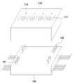
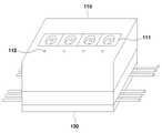
도 1은 본 발명의 일 실시예에 따른 PDU(Power Distribution Unit)의 개념 설명에 제공되는 도면이다. PDU의 전체는 도 7에 도시되어 있다. 도 1에는, 본 발명의 실시예에 따른 PDU의 개념 설명을 위해 일부만을 도시한 것이다.1 is a diagram illustrating a concept of a PDU (Power Distribution Unit) according to an embodiment of the present invention. The entire PDU is shown in Fig. FIG. 1 shows only a part of the PDU according to an embodiment of the present invention.
본 발명의 실시예에 따른 PDU는, IDC(Internet Data Center) 내에서 다수의 서버 랙들에 전원을 공급하기 위한 것으로 활용가능하지만, 이는 예시적인 용도로, 다른 용도로 사용되는 것을 배제하지 않는다.A PDU according to an embodiment of the present invention may be utilized to supply power to a plurality of server racks in an IDC (Internet Data Center), but this does not exclude that it is used for other purposes for exemplary purposes.
이와 같은 기능을 수행하는 PDU는, 도 1에 도시된 바와 같이, 멀티 소켓 모듈(110) 및 베이스(120)를 포함한다.A PDU performing such a function includes a
베이스(120)는 외부로부터 전원을 입력받아 멀티 소켓 모듈(110)로 전달하기 위한 수단으로, 상용 전원과 비상 전원을 입력/전달한다. 상용 전원은 한전에서 공급하는 전원으로 상용 전원 출력단(121)에서 출력되며, 비상 전원은 IDC 내에 설치된 UPS(Uninterruptible Power Supply)로부터 공급되는 전원으로 비상 전원 출력단(122)에서 출력된다.The
즉, 본 발명의 실시예에 따른 PDU는, 전기적인 리던던시(Redundancy)를 위해 상용 전원 외에 비상 전원을 포함한 이종의 전원을 공급한다.That is, the PDU according to the embodiment of the present invention supplies a different power source including an emergency power source in addition to a commercial power source for electrical redundancy.
멀티 소켓 모듈(110)은 멀티 소켓(111)과 상태 표시등(112)을 포함한다. 멀티 소켓(111)에는 서버들의 플러그가 연결되고, 상태 표시등(112)은 해당 소켓이 전원 전달이 가능한 상태인 경우에 점등된다.The
멀티 소켓 모듈(110)은, 베이스(120)에 연결되어, 베이스(120)에서 출력되는 전원을 멀티 소켓(111)을 통해 출력하여, 멀티 소켓(111)에 플러그가 연결된 서버들로 전원을 전달한다.The
멀티 소켓 모듈(110)이 베이스(120)로부터 전달받는 전원의 종류는, 멀티 소켓 모듈(110)과 베이스(120)의 결합 방향에 의해 결정된다.The type of power received from the
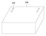
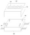
구체적으로, 멀티 소켓 모듈(110)의 저면에는, 도 2에 도시된 바와 같이, 전원 입력단(113)이 하나만 마련되어 있다. 도 2는 멀티 소켓 모듈(110)을 멀티 소켓(111)의 길이 방향을 축으로 하여 180도 회전시킨 도면이다.Specifically, only one
따라서, 이 전원 입력단(113)이 베이스(120)의 상용 전원 출력단(121)에 연결되면 멀티 소켓(111)에서는 상용 전원이 출력되는 반면, 전원 입력단(113)이 베이스(120)의 비상 전원 출력단(122)에 연결되면 멀티 소켓(111)에서는 비상 전원이 출력된다.When the
도 3에는 멀티 소켓 모듈(110)이 상용 전원을 전달할 수 있도록 베이스(120)에 결합된 상태를 도시하였다.3 shows a state in which the
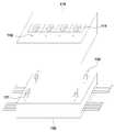
한편, 도 4에는 멀티 소켓 모듈(110)이 베이스(120)의 비상 전원 출력단(122)에 결합 가능한 상태로 부상되어 있는 상태를 도시하였다. 도 1에 도시된 멀티 소켓 모듈(110)과 상태 표시등(112)의 위치가 반대가 되었음을 확인할 수 있다.4 shows a state in which the
또한, 도 5에는 멀티 소켓 모듈(110)을 멀티 소켓(111)의 길이 방향을 축으로 하여 180도 회전시킨 도면이다. 도 2에 도시된 멀티 소켓 모듈(110)과 전원 입력단(113)의 위치가 반대가 되었음을 확인할 수 있다.5, the
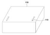
그리고, 도 6에는 멀티 소켓 모듈(110)이 비상 전원을 전달할 수 있도록 베이스(120)에 결합된 상태를 도시하였다. 마찬가지로, 도 3에 도시된 멀티 소켓 모듈(110)과 상태 표시등(112)의 위치가 반대임을 확인할 수 있다.6 shows a state in which the
한편, 베이스(120)의 측면 또는 출력단(121, 122) 주변에는, 출력단(121, 122)을 통해 출력되는 전원의 종류(상용 전원, 비상 전원)를 안내하기 위한 문구, 마크, 기타 다양한 표식이 표시되어 있을 수 있다.Marks and other various markings for guiding the type of power source (commercial power source, emergency power source) output through the
도 7은 본 발명의 일 실시예에 따른 PDU를 도시한 도면이다. 도 7에 도시된 바와 같이, 본 발명의 실시예에 따른 PDU의 베이스(120)에는 5개의 멀티 소켓 모듈(110)이 결합될 수 있도록 설계되었는데, "5개"는 예시적인 숫자에 불과하다. 즉, "5개"를 초과하거나 그 보다 작은 개수의 멀티 소켓 모듈(110)이 결합될 수 있도록 베이스(120)를 설계하는 것이 가능하다.7 is a diagram illustrating a PDU according to an embodiment of the present invention. As shown in FIG. 7, five
한편, 베이스(120)에 멀티 소켓 모듈(110)이 결합함에 있어, 수용가능한 개수 전부가 결합 되어져야 하는 것은 아니다. 그 보다 작은 개수의 멀티 소켓 모듈(110)이 결합 되어져도 무방하다. 예를 들어, 베이스(120)에 수용가능한 멀티 소켓 모듈(110)의 개수 전부가 5개인데, 4개의 멀티 소켓 모듈(110)을 결합시켜 사용하는 것이 가능한 것이다.On the other hand, when the
더 나아가, 베이스(120)도 모듈형으로 구현하여, 결합가능한 멀티 소켓 모듈(110)의 개수를 모듈 조립으로 결정하는 것도 가능하다.Furthermore, it is also possible to implement the
또한, 멀티 소켓 모듈(110)에는 멀티 소켓(111)의 규격과 다른 규격을 갖는 멀티 소켓이 구비되어져도 무방하다. 예를 들어, 도 8에 도시된 바와 같이, 멀티 소켓(111)과 다른 규격의 멀티 소켓(114)이 마련되어 있는 멀티 소켓 모듈(110)도 베이스(120)에 결합하여 사용할 수 있다.Further, the
나아가, 베이스(120)에 결합되는 멀티 소켓 모듈(110)들에 구현되는 멀티 소켓의 규격은 멀티 소켓 모듈들 마다 서로 달라도 무방하다.Further, the specification of the multi-socket implemented in the
즉, 본 발명의 실시예에 따른 PDU는 IDC의 서버 환경에 따라 맞춤형으로 구성하여 사용할 수 있음은 물론, 추후 변경이나 확장을 자유롭게 하는 것이 가능하다.That is, the PDU according to the embodiment of the present invention can be customized and used according to the server environment of the IDC, and can be changed or expanded later.
지금까지, 이종 전원 공급이 가능한 모듈형 PDU에 대해, 바람직한 실시예를 들어 상세히 설명하였다.Up to now, a modular PDU capable of heterogeneous power supply has been described in detail with a preferred embodiment.
본 실시예에서는 PDU가 2가지 전원을 선택적으로 공급하는 경우를 상정하였으나, 설명의 편의를 위한 예시적인 것에 불과하다. 3가지 이상의 전원을 선택적으로 공급하는 경우에도 본 발명의 기술적 사상이 적용될 수 있다.In the present embodiment, it is assumed that the PDU selectively supplies two power sources, but this is merely an example for convenience of explanation. The technical idea of the present invention can be applied even when three or more power sources are selectively supplied.
나아가, 제시한 소켓의 규격 역시 예시적인 것으로, 제시되지 않은 규격의 소켓에도 본 발명의 기술적 사상이 적용될 수 있다.Furthermore, the specification of the socket presented is also exemplary, and the technical idea of the present invention can be applied to a socket of a standard not shown.
또한, 이상에서는 본 발명의 바람직한 실시예에 대하여 도시하고 설명하였지만, 본 발명은 상술한 특정의 실시예에 한정되지 아니하며, 청구범위에서 청구하는 본 발명의 요지를 벗어남이 없이 당해 발명이 속하는 기술분야에서 통상의 지식을 가진자에 의해 다양한 변형실시가 가능한 것은 물론이고, 이러한 변형실시들은 본 발명의 기술적 사상이나 전망으로부터 개별적으로 이해되어져서는 안될 것이다.
While the present invention has been particularly shown and described with reference to exemplary embodiments thereof, it is to be understood that the invention is not limited to the disclosed exemplary embodiments, but, on the contrary, It will be understood by those skilled in the art that various changes in form and details may be made therein without departing from the spirit and scope of the present invention.
110 : 멀티 소켓 모듈
111 : 멀티 소켓112 : 상태 표시등
120 : 베이스
121 : 상용 전원 출력단122 : 비상 전원 출력단110: Multi-socket module
111: Multi-socket 112: Status indicator
120: Base
121: Commercial power output stage 122: Emergency power output stage
Claims (6)
Translated fromKorean상기 베이스에 연결되어, 상기 전원들 중 한 종류의 전원을 플러그가 연결된 기기들에 전달하는 멀티 소켓 모듈;을 포함하고,
상기 멀티 소켓 모듈은,
상기 베이스에 제1 방향으로 연결되면, 상기 전원들 중 제1 전원을 상기 기기들에 전달하고,
상기 베이스에 제2 방향으로 연결되면, 상기 전원들 중 제2 전원을 상기 기기들에 전달하는 것을 특징으로 하는 PDU(Power Distribution Unit).
A base for transmitting different kinds of power sources; And
And a multi-socket module, connected to the base, for transmitting a power of one of the power sources to devices connected to the plug,
The multi-
And a second power source connected to the base, the first power source being connected to the base in a first direction,
And a second power source connected to the base in a second direction to transmit the second power source to the devices.
상기 제1 전원은, 상용 전원이고,
상기 제2 전원은, 비상 전원인 것을 특징으로 하는 PDU.
The method according to claim 1,
The first power source is a commercial power source,
And the second power source is an emergency power source.
상기 베이스는,
상기 멀티 소켓 모듈로 상기 제1 전원을 출력하는 제1 출력단; 및
상기 멀티 소켓 모듈로 상기 제2 전원을 출력하는 제2 출력단;을 포함하고,
상기 제1 출력단의 주변에는, 상기 제1 전원의 종류를 안내하는 표시가 있고,
상기 제2 출력단의 주변에는, 상기 제2 전원의 종류를 안내하는 표시가 있는 것을 특징으로 하는 PDU.
The method according to claim 1,
The base includes:
A first output terminal for outputting the first power to the multi-socket module; And
And a second output terminal for outputting the second power to the multi-socket module,
Wherein a display for guiding the type of the first power source is provided in the periphery of the first output terminal,
And a periphery of the second output terminal has an indication to guide the type of the second power source.
상기 베이스에는,
다수의 멀티 소켓 모듈이 연결가능한 것을 특징으로 하는 PDU.
The method according to claim 1,
In the base,
A plurality of multi-socket modules are connectable.
상기 베이스에는,
소켓의 규격이 각기 다른 멀티 소켓 모듈이 연결가능한 것을 특징으로 하는 PDU.
The method according to claim 1,
In the base,
A PDU characterized in that a multi-socket module with different socket sizes is connectable.
Priority Applications (2)
| Application Number | Priority Date | Filing Date | Title |
|---|---|---|---|
| KR1020130168083AKR101535192B1 (en) | 2013-12-31 | 2013-12-31 | Module Type PDU for Different Power Supply |
| US14/575,155US9450357B2 (en) | 2013-12-31 | 2014-12-18 | Module type power distribution unit having a multi socket module for selectively supplying different kinds of power |
Applications Claiming Priority (1)
| Application Number | Priority Date | Filing Date | Title |
|---|---|---|---|
| KR1020130168083AKR101535192B1 (en) | 2013-12-31 | 2013-12-31 | Module Type PDU for Different Power Supply |
Publications (2)
| Publication Number | Publication Date |
|---|---|
| KR20150080207A KR20150080207A (en) | 2015-07-09 |
| KR101535192B1true KR101535192B1 (en) | 2015-07-10 |
Family
ID=53482954
Family Applications (1)
| Application Number | Title | Priority Date | Filing Date |
|---|---|---|---|
| KR1020130168083AExpired - Fee RelatedKR101535192B1 (en) | 2013-12-31 | 2013-12-31 | Module Type PDU for Different Power Supply |
Country Status (2)
| Country | Link |
|---|---|
| US (1) | US9450357B2 (en) |
| KR (1) | KR101535192B1 (en) |
Families Citing this family (5)
| Publication number | Priority date | Publication date | Assignee | Title |
|---|---|---|---|---|
| US9972468B2 (en)* | 2015-06-16 | 2018-05-15 | Eaton Intelligent Power Limited | Information technology racks having integrated bus plugs and related systems and busways |
| WO2017131250A1 (en)* | 2016-01-27 | 2017-08-03 | 전자부품연구원 | Method for expandably/separably supplying various power sources, and power distribution device applying the same |
| US10524377B2 (en) | 2018-01-31 | 2019-12-31 | Eaton Intelligent Power Limited | Power distribution unit with interior busbars |
| CN112751262B (en)* | 2019-10-31 | 2023-10-27 | 深圳市中科达沃技术有限公司 | Intelligent PDU product |
| TWI808031B (en)* | 2022-11-02 | 2023-07-01 | 阡群企業有限公司 | Modular socket system with automatic power off |
Citations (1)
| Publication number | Priority date | Publication date | Assignee | Title |
|---|---|---|---|---|
| JP2011044344A (en)* | 2009-08-21 | 2011-03-03 | Tsubaki Emerson Co | Socket |
Family Cites Families (13)
| Publication number | Priority date | Publication date | Assignee | Title |
|---|---|---|---|---|
| US5466974A (en)* | 1993-02-19 | 1995-11-14 | Sundstrand Corporation | Electric power distribution module for an electric power generation and distribution system |
| US5579201A (en)* | 1995-08-23 | 1996-11-26 | Karageozian; Vicken H. | Modified electrical strip for energizing/de-energizing secondary devices simultaneously with a main device |
| US5821636A (en)* | 1997-08-08 | 1998-10-13 | Compaq Computer Corp. | Low profile, redundant source power distribution unit |
| TW459425B (en)* | 2000-06-23 | 2001-10-11 | Primax Electronics Ltd | Power socket apparatus |
| US6744150B2 (en)* | 2001-12-03 | 2004-06-01 | Neven V. Rendic | Outlet strip controlled by PC using low voltage powertap |
| US7208850B2 (en)* | 2003-09-02 | 2007-04-24 | Generac Power Systems, Inc. | Power strip transfer mechanism |
| KR100489187B1 (en)* | 2004-08-30 | 2005-05-11 | 윤종찬 | Molded power distributing panel |
| US20080013909A1 (en)* | 2006-07-14 | 2008-01-17 | Tenvera, Inc. | Modular Optical Fiber Network Interface |
| CN101682200A (en)* | 2007-03-14 | 2010-03-24 | 佐尼特结构解决方案有限责任公司 | Automatic switching duplex module of American national electrical manufacturing association |
| US7897886B1 (en)* | 2008-04-15 | 2011-03-01 | Reliance Controls Corporation | Non-transfer switch for providing power from an alternate power source in a non-separately derived power management system |
| US8355832B2 (en)* | 2010-02-12 | 2013-01-15 | Glenn Rosendahl | Controlling power supply to vehicles through a series of electrical outlets |
| US8094436B2 (en)* | 2010-03-29 | 2012-01-10 | Eaton Corporation | Plug-in circuit breaker assembly |
| US8882536B2 (en)* | 2012-01-27 | 2014-11-11 | Chatsworth Products, Inc. | Power distribution unit with interchangeable outlet adapter types |
- 2013
- 2013-12-31KRKR1020130168083Apatent/KR101535192B1/ennot_activeExpired - Fee Related
- 2014
- 2014-12-18USUS14/575,155patent/US9450357B2/enactiveActive
Patent Citations (1)
| Publication number | Priority date | Publication date | Assignee | Title |
|---|---|---|---|---|
| JP2011044344A (en)* | 2009-08-21 | 2011-03-03 | Tsubaki Emerson Co | Socket |
Also Published As
| Publication number | Publication date |
|---|---|
| US20150188269A1 (en) | 2015-07-02 |
| US9450357B2 (en) | 2016-09-20 |
| KR20150080207A (en) | 2015-07-09 |
Similar Documents
| Publication | Publication Date | Title |
|---|---|---|
| KR101535192B1 (en) | Module Type PDU for Different Power Supply | |
| CN102866729B (en) | Server cabinet system | |
| US20150261710A1 (en) | Low-profile half length pci express form factor embedded pci express multi ports switch and related accessories | |
| CN107112795B (en) | Modular uninterruptible power supply and power distribution system | |
| US20120290246A1 (en) | Test systems with cables that support multiple communications buses | |
| WO2020136010A3 (en) | Base module and functional module for an electrical enclosure system, and electrical enclosure system | |
| US9454191B2 (en) | ATCA backplane | |
| TWI453577B (en) | Power source equipment for cabinet for server | |
| EP3312687A3 (en) | On machine input/output (i/o) system with modular connections | |
| KR102010112B1 (en) | Module Type PDU for Various AC Power Supply | |
| JP2016197100A (en) | Reconfiguration of large-scale automatic test system | |
| US6659803B1 (en) | Power supply arrangement for server | |
| US20180032119A1 (en) | Redundant power extender | |
| KR20170076999A (en) | Module Type PDU for Various DC Power Supply | |
| US20130290739A1 (en) | Sharing power between network devices | |
| CN103324264A (en) | Power supply device of cabinet | |
| CN102395988A (en) | Card device and power supply method for card device | |
| US20180166839A1 (en) | Power distribution unit and electronic device using the same | |
| JP4718338B2 (en) | Electronic device, power supply unit and logic unit mounted on the electronic device | |
| US20140013130A1 (en) | Expansion circuit for server system and server system using same | |
| US20130178112A1 (en) | Connection Interface and Cable | |
| HK1250458A2 (en) | A drone and control device and communication port device thereof | |
| CN205318148U (en) | A backplate and remote control unit RTU for remote control unit RTU | |
| CN103067181B (en) | Frame type equipment and electric power system thereof | |
| CN119065478A (en) | Expandable power distribution system and method |
Legal Events
| Date | Code | Title | Description |
|---|---|---|---|
| PA0109 | Patent application | St.27 status event code:A-0-1-A10-A12-nap-PA0109 | |
| PA0201 | Request for examination | St.27 status event code:A-1-2-D10-D11-exm-PA0201 | |
| D13-X000 | Search requested | St.27 status event code:A-1-2-D10-D13-srh-X000 | |
| D14-X000 | Search report completed | St.27 status event code:A-1-2-D10-D14-srh-X000 | |
| PE0902 | Notice of grounds for rejection | St.27 status event code:A-1-2-D10-D21-exm-PE0902 | |
| E13-X000 | Pre-grant limitation requested | St.27 status event code:A-2-3-E10-E13-lim-X000 | |
| P11-X000 | Amendment of application requested | St.27 status event code:A-2-2-P10-P11-nap-X000 | |
| P13-X000 | Application amended | St.27 status event code:A-2-2-P10-P13-nap-X000 | |
| E701 | Decision to grant or registration of patent right | ||
| PE0701 | Decision of registration | St.27 status event code:A-1-2-D10-D22-exm-PE0701 | |
| GRNT | Written decision to grant | ||
| PR0701 | Registration of establishment | St.27 status event code:A-2-4-F10-F11-exm-PR0701 | |
| PR1002 | Payment of registration fee | St.27 status event code:A-2-2-U10-U11-oth-PR1002 Fee payment year number:1 | |
| PG1501 | Laying open of application | St.27 status event code:A-1-1-Q10-Q12-nap-PG1501 | |
| PG1601 | Publication of registration | St.27 status event code:A-4-4-Q10-Q13-nap-PG1601 | |
| FPAY | Annual fee payment | Payment date:20180627 Year of fee payment:4 | |
| PR1001 | Payment of annual fee | St.27 status event code:A-4-4-U10-U11-oth-PR1001 Fee payment year number:4 | |
| FPAY | Annual fee payment | Payment date:20190702 Year of fee payment:5 | |
| PR1001 | Payment of annual fee | St.27 status event code:A-4-4-U10-U11-oth-PR1001 Fee payment year number:5 | |
| PR1001 | Payment of annual fee | St.27 status event code:A-4-4-U10-U11-oth-PR1001 Fee payment year number:6 | |
| R18-X000 | Changes to party contact information recorded | St.27 status event code:A-5-5-R10-R18-oth-X000 | |
| PR1001 | Payment of annual fee | St.27 status event code:A-4-4-U10-U11-oth-PR1001 Fee payment year number:7 | |
| PR1001 | Payment of annual fee | St.27 status event code:A-4-4-U10-U11-oth-PR1001 Fee payment year number:8 | |
| PN2301 | Change of applicant | St.27 status event code:A-5-5-R10-R13-asn-PN2301 St.27 status event code:A-5-5-R10-R11-asn-PN2301 | |
| PN2301 | Change of applicant | St.27 status event code:A-5-5-R10-R13-asn-PN2301 St.27 status event code:A-5-5-R10-R11-asn-PN2301 | |
| PR1001 | Payment of annual fee | St.27 status event code:A-4-4-U10-U11-oth-PR1001 Fee payment year number:9 | |
| PC1903 | Unpaid annual fee | St.27 status event code:A-4-4-U10-U13-oth-PC1903 Not in force date:20240703 Payment event data comment text:Termination Category : DEFAULT_OF_REGISTRATION_FEE | |
| PC1903 | Unpaid annual fee | St.27 status event code:N-4-6-H10-H13-oth-PC1903 Ip right cessation event data comment text:Termination Category : DEFAULT_OF_REGISTRATION_FEE Not in force date:20240703 |