KR101534985B1 - A friction adjustment method of MDPS[Moter driven power steering] and the apparatus thereof - Google Patents
A friction adjustment method of MDPS[Moter driven power steering] and the apparatus thereofDownload PDFInfo
- Publication number
- KR101534985B1 KR101534985B1KR1020130165247AKR20130165247AKR101534985B1KR 101534985 B1KR101534985 B1KR 101534985B1KR 1020130165247 AKR1020130165247 AKR 1020130165247AKR 20130165247 AKR20130165247 AKR 20130165247AKR 101534985 B1KR101534985 B1KR 101534985B1
- Authority
- KR
- South Korea
- Prior art keywords
- signal
- vehicle
- control device
- road surface
- active control
- Prior art date
- Legal status (The legal status is an assumption and is not a legal conclusion. Google has not performed a legal analysis and makes no representation as to the accuracy of the status listed.)
- Active
Links
- 238000000034methodMethods0.000titleclaimsabstractdescription72
- 208000035278mandibuloacral dysplasia progeroid syndromeDiseases0.000title1
- 230000001133accelerationEffects0.000claimsdescription33
- 230000007547defectEffects0.000claimsdescription5
- 230000002950deficientEffects0.000claimsdescription4
- 230000004913activationEffects0.000claimsdescription3
- 238000004441surface measurementMethods0.000claimsdescription3
- 230000001105regulatory effectEffects0.000claims1
- 230000008569processEffects0.000description18
- 230000008859changeEffects0.000description15
- 238000010586diagramMethods0.000description12
- 230000001788irregularEffects0.000description9
- 238000012986modificationMethods0.000description3
- 230000004048modificationEffects0.000description3
- 238000012545processingMethods0.000description3
- 238000004891communicationMethods0.000description2
- 230000006835compressionEffects0.000description2
- 238000007906compressionMethods0.000description2
- 230000009467reductionEffects0.000description2
- 230000005856abnormalityEffects0.000description1
- 238000007792additionMethods0.000description1
- 239000010426asphaltSubstances0.000description1
- 230000008901benefitEffects0.000description1
- 230000003750conditioning effectEffects0.000description1
- 230000000694effectsEffects0.000description1
- 238000001914filtrationMethods0.000description1
- 239000000446fuelSubstances0.000description1
- 238000013507mappingMethods0.000description1
- 238000004904shorteningMethods0.000description1
- 238000006467substitution reactionMethods0.000description1
- 238000010977unit operationMethods0.000description1
Images


Classifications
- B—PERFORMING OPERATIONS; TRANSPORTING
- B60—VEHICLES IN GENERAL
- B60W—CONJOINT CONTROL OF VEHICLE SUB-UNITS OF DIFFERENT TYPE OR DIFFERENT FUNCTION; CONTROL SYSTEMS SPECIALLY ADAPTED FOR HYBRID VEHICLES; ROAD VEHICLE DRIVE CONTROL SYSTEMS FOR PURPOSES NOT RELATED TO THE CONTROL OF A PARTICULAR SUB-UNIT
- B60W40/00—Estimation or calculation of non-directly measurable driving parameters for road vehicle drive control systems not related to the control of a particular sub unit, e.g. by using mathematical models
- B60W40/02—Estimation or calculation of non-directly measurable driving parameters for road vehicle drive control systems not related to the control of a particular sub unit, e.g. by using mathematical models related to ambient conditions
- B60W40/06—Road conditions
- B60W40/068—Road friction coefficient
- B—PERFORMING OPERATIONS; TRANSPORTING
- B62—LAND VEHICLES FOR TRAVELLING OTHERWISE THAN ON RAILS
- B62D—MOTOR VEHICLES; TRAILERS
- B62D6/00—Arrangements for automatically controlling steering depending on driving conditions sensed and responded to, e.g. control circuits
- B62D6/002—Arrangements for automatically controlling steering depending on driving conditions sensed and responded to, e.g. control circuits computing target steering angles for front or rear wheels
- B62D6/006—Arrangements for automatically controlling steering depending on driving conditions sensed and responded to, e.g. control circuits computing target steering angles for front or rear wheels using a measured or estimated road friction coefficient
- B—PERFORMING OPERATIONS; TRANSPORTING
- B60—VEHICLES IN GENERAL
- B60W—CONJOINT CONTROL OF VEHICLE SUB-UNITS OF DIFFERENT TYPE OR DIFFERENT FUNCTION; CONTROL SYSTEMS SPECIALLY ADAPTED FOR HYBRID VEHICLES; ROAD VEHICLE DRIVE CONTROL SYSTEMS FOR PURPOSES NOT RELATED TO THE CONTROL OF A PARTICULAR SUB-UNIT
- B60W10/00—Conjoint control of vehicle sub-units of different type or different function
- B60W10/20—Conjoint control of vehicle sub-units of different type or different function including control of steering systems
- B—PERFORMING OPERATIONS; TRANSPORTING
- B62—LAND VEHICLES FOR TRAVELLING OTHERWISE THAN ON RAILS
- B62D—MOTOR VEHICLES; TRAILERS
- B62D5/00—Power-assisted or power-driven steering
- B62D5/04—Power-assisted or power-driven steering electrical, e.g. using an electric servo-motor connected to, or forming part of, the steering gear
- B—PERFORMING OPERATIONS; TRANSPORTING
- B62—LAND VEHICLES FOR TRAVELLING OTHERWISE THAN ON RAILS
- B62D—MOTOR VEHICLES; TRAILERS
- B62D6/00—Arrangements for automatically controlling steering depending on driving conditions sensed and responded to, e.g. control circuits
- B—PERFORMING OPERATIONS; TRANSPORTING
- B62—LAND VEHICLES FOR TRAVELLING OTHERWISE THAN ON RAILS
- B62D—MOTOR VEHICLES; TRAILERS
- B62D6/00—Arrangements for automatically controlling steering depending on driving conditions sensed and responded to, e.g. control circuits
- B62D6/008—Control of feed-back to the steering input member, e.g. simulating road feel in steer-by-wire applications
Landscapes
- Engineering & Computer Science (AREA)
- Transportation (AREA)
- Mechanical Engineering (AREA)
- Chemical & Material Sciences (AREA)
- Combustion & Propulsion (AREA)
- Physics & Mathematics (AREA)
- Mathematical Physics (AREA)
- Automation & Control Theory (AREA)
- Steering Control In Accordance With Driving Conditions (AREA)
- Vehicle Body Suspensions (AREA)
- Control Of Driving Devices And Active Controlling Of Vehicle (AREA)
Abstract
Description
Translated fromKorean본 발명은 전동식 조향 장치의 프릭션(friction) 조절 방법 및 프릭션 조절 장치에 관한 것으로, 도로 노면의 상황이나 가속 또는 감속 상황에 맞추어서 최적의 조향감을 제공할 수 있는 전동식 조향 장치에 관한 것이다.
BACKGROUND OF THE INVENTION Field of the Invention [0001] The present invention relates to a friction control method and a friction control device for an electric steering system, and more particularly, to an electric steering system capable of providing an optimum steering feeling in accordance with a road surface condition or an acceleration or deceleration condition.
최근 많은 차량의 조향 장치로 엠디피에스(MDPS, Motor driven power steering) 시스템이 장착되고 있다. 이러한 엠디피에스 장치는 기존 유압식 파워 스티어링 대비 연비가 향상되고, 부품 수 감소로 인한 작업 공정을 단축시킬 수 있다는 장점이 있다.Recently, a motor driven power steering (MDPS) system has been installed as a steering device for many vehicles. This MDPS device has the advantage of improving the fuel efficiency compared to the conventional hydraulic power steering and shortening the work process due to the reduction of the number of parts.
하지만, 종래의 엠디피에스 장치의 경우는 도로 노면의 상태가 바뀌더라도 그에 대한 조타감은 기존의 동일한 튜닝 맵(tuning map)에 반영되었으므로, 조향계의 마찰감을 가변하지 못하였다. 그리고, 이는 젖은 노면이나 눈길 등 도로 마찰계수가 낮은 노면에서는 핸들(handle)이 가벼워지는 현상을 야기하였고, 비포장도로에서는 조향계의 프릭션이 낮아서, 핸들이 좌우로 가볍게 돌아가는 현상이 발생하여서 운전자에게 최적의 조향감을 전달하지 못하는 문제점이 있었다.
However, in the case of the conventional MDP device, even if the state of the road surface changes, the sense of steering is reflected in the same tuning map, so that the friction feeling of the steering system can not be changed. This causes a handle to be lightened on a road surface having a low road friction coefficient such as a wet road surface or an eye road. On the unpaved road, the friction of the steering system is low and the steering wheel turns lightly to the left and right. There is a problem that the optimum steering feeling can not be transmitted.
본 발명은 상기와 같은 문제점을 해결하기 위해 안출된 것으로, 도로 노면의 상황을 감지하여 조향 장치의 마찰감 및 조향감을 최적화할 수 있는 엠디피에스 장치를 제공하고자 한다.SUMMARY OF THE INVENTION The present invention has been made to solve the above-mentioned problems, and it is an object of the present invention to provide an MDS device capable of sensing the road surface condition and optimizing the friction feeling and steering feeling of the steering device.
상기한 목적을 달성하기 위해, 본 발명에서는 차량이 주행하는 노면의 상태가 감지되는 단계; 상기 차량이 주행하는 노면이 일반 도로, 저마찰 도로, 제1 불균일 노면을 지닌 도로 또는 제2 불균일 노면을 지닌 도로로 분류되는 단계; 상기 차량이 주행하는 노면이 일반 도로로 판단되는 경우, 상기 차량의 전동식 조향 장치(MDPS, Motor driven power steering)의 프릭션(friction)을 감소시키도록 조절되는 단계;가 포함되는 것을 특징으로 하는 전동식 조향 장치의 프릭션 조절 방법을 제공한다.To achieve the above object, according to the present invention, there is provided a method of driving a vehicle, comprising: sensing a state of a road surface on which a vehicle travels; The road surface on which the vehicle travels is classified as a road having a general road, a low-friction road, a road having a first uneven road surface, or a road having a second uneven road surface; And adjusting the friction of the motor driven power steering (MDPS) of the vehicle when the road surface on which the vehicle travels is determined to be a general road. Provides a method for adjusting the friction of the device.
또한, 본 발명에서는 차량이 주행하는 노면의 상태가 감지되는 단계; 상기 차량이 주행하는 노면이 일반 도로, 저마찰 도로, 제1 불균일 노면을 지닌 도로 또는 제2 불균일 노면을 지닌 도로로 분류되는 단계; 상기 차량이 주행하는 노면이 저마찰 도로 또는 불균일 노면을 지닌 도로로 분류되는 경우, 상기 차량의 전동식 조향 장치의 프릭션을 증가시키도록 조절되는 단계;가 포함되는 것을 특징으로 하는 전동식 조향 장치의 프릭션 조절 방법을 제공한다.According to another aspect of the present invention, The road surface on which the vehicle travels is classified as a road having a general road, a low-friction road, a road having a first uneven road surface, or a road having a second uneven road surface; And adjusting the friction of the electric motor-driven steering device of the vehicle when the road surface on which the vehicle travels is classified as a road having a low friction road or a non-uniform road surface Provides a method of adjustment.
또한, 상기 차량이 주행하는 노면이 일반 도로, 저마찰 도로, 제1 불균일 노면을 지닌 도로 또는 제2 불균일 노면을 지닌 도로로 분류되는 단계는, 상기 차량의 컬럼토크(column torque), 전동식 조향 장치의 출력, 조향각, 조향각속도, 차속, 휠 스피드(wheel speed), 차량통합제어장치(VSM, Vehicle stability management) 동작 신호를 입력받고, 상기 차량의 좌우 타이어(tire)의 휠 스피드의 차가 기설정된 제1 불균일 기준치보다 크고 기설정된 제2 불균일 기준치보다 작으면 제1 불균일 노면으로 판단되고, 상기 차량의 좌우 타이어의 휠 스피드의 차가 기설정된 제2 불균일 기준치보다 크면 제2 불균일 노면으로 판단되며, 상기 컬럼 토크 값을 기설정된 토크 값으로 나눈 값이 '1'보다 작으면 저마찰 도로로 판단되고, 그 이외는 일반 도로로 판단되는 것을 것을 특징으로 하는 전동식 조향 장치의 프릭션 조절 방법을 제공한다.Also, the step of classifying the road surface on which the vehicle travels into a road, a low friction road, a road having a first irregular road surface, or a road having a second irregular road surface may be classified into a column torque of the vehicle, And a vehicle stability control (VSM) operation signal, wherein the difference between the wheel speeds of the left and right tires of the vehicle is set to a predetermined first And when the difference between the wheel speeds of the left and right tires of the vehicle is greater than a predetermined second non-uniformity reference value, the second uneven road surface is determined as the second non-uniform road surface, Friction road is judged to be a low-friction road when the value obtained by dividing the value by the predetermined torque value is less than " 1 ", and the other roads are judged to be an ordinary road A method of adjusting friction of an electric steering system is provided.
또한, 상기 차량이 주행하는 노면이 저마찰 도로, 제1 불균일 노면을 지닌 도로 또는 제2 불균일 노면을 지닌 도로로 분류되는 경우, 상기 차량의 전동식 조향 장치의 프릭션을 증가시키도록 조절되는 단계는, 상기 차량이 주행하는 노면이 저마찰 도로로 분류되고, 차량통합제어장치의 동작 신호가 없으면, 상기 전동식 조향 장치의 능동제어장치(ARS, Active roll stabilizer)의 지지력이 기설정된 제3 지지력 값으로 조절되고, 상기 차량이 주행하는 노면이 저마찰 도로로 분류되고, 차세통합제어장치의 동작 신호가 있으면, 상기 전동식 조향 장치의 능동제어장치의 지지력이 기설정된 제1 지지력 값으로 조절되는 것을 특징으로 하는 전동식 조향 장치의 프릭션 조절 방법을 제공한다.In addition, when the road surface on which the vehicle travels is classified as a road having a low friction road, a road having the first irregular road surface or a road having the second irregular road surface, the step of adjusting the friction of the electric motor- If the road surface on which the vehicle travels is classified as a low friction road and there is no operation signal of the integrated vehicle control device, the supporting force of the active control device (ARS) of the electric steering system is adjusted to a predetermined third supporting force value , And the road surface on which the vehicle travels is classified as a low friction road, and when there is an operation signal of the tertiary integrated controller, the supporting force of the active control device of the electric power steering apparatus is adjusted to a predetermined first supporting force value Provides a method for adjusting the friction of the device.
또한, 상기 차량이 주행하는 노면이 저마찰 도로, 제1 불균일 노면을 지닌 도로 또는 제2 불균일 노면을 지닌 도로로 분류되는 경우, 상기 차량의 전동식 조향 장치의 프릭션을 증가시키도록 조절되는 단계는, 상기 차량이 주행하는 노면이 제1 불균일 노면을 지닌 도로로 분류되는 경우, 상기 전동식 조향 장치의 능동제어장치의 지지력이 기설정된 제2 지지력 값으로 조절되며, 상기 차량이 주행하는 노면이 제2 불균일 노면을 지닌 도로로 분류되는 경우, 상기 전동식 조향 장치의 능동제어장치의 지지력이 기설정된 제1 지지력 값으로 조절되는 것을 특징으로 하는 전동식 조향 장치의 프릭션 조절 방법을 제공한다.In addition, when the road surface on which the vehicle travels is classified as a road having a low friction road, a road having the first irregular road surface or a road having the second irregular road surface, the step of adjusting the friction of the electric motor- Wherein when the road surface on which the vehicle travels is classified as a road having a first nonuniform road surface, the supporting force of the active control device of the electric-powered steering apparatus is adjusted to a predetermined second supporting force value, The supporting force of the active control device of the electric power steering apparatus is adjusted to a predetermined first supporting force value.
또한, 본 발명은 차량이 기설정된 일정 가속도 이상으로 가속되거나 또는 기설정된 일정 감속도 이상으로 감속되는지 여부가 측정되는 단계; 상기 차량이 기설정된 일정 가속도 이상으로 가속되거나 또는 기설정된 일정 감속도 이상으로 감속되면 상기 차량의 전동식 조향 장치의 프릭션을 증가시키도록 조절되는 단계;가 포함되는 것을 특징으로 하는 전동식 조향 장치의 프릭션 조절 방법을 제공한다.Further, the present invention is characterized in that it is measured whether the vehicle is accelerated above a predetermined constant acceleration or decelerated to a predetermined constant deceleration or more; And adjusting the friction of the electric motor-driven steering device of the vehicle when the vehicle is accelerated to a predetermined constant acceleration or decelerated to a predetermined constant deceleration or more. And provides a method for adjusting the temperature.
또한, 상기 차량이 기설정된 일정 가속도 이상으로 가속되거나 또는 기설정된 일정 감속도 이상으로 감속되면 상기 차량의 전동식 조향 장치의 프릭션을 증가시키도록 조절되는 단계는 상기 전동식 조향 장치의 능동제어장치의 지지력이 기설정된 제1 지지력 값으로 조절되는 것을 특징으로 하는 전동식 조향 장치의 프릭션 조절 방법을 제공한다.In addition, when the vehicle is accelerated above a preset constant acceleration or decelerated to a predetermined constant deceleration or higher, the step of adjusting the frictional resistance of the electric motor-driven steering device of the vehicle may include: Wherein the first support force value is adjusted to a predetermined first support force value.
또한, 상기 제1 지지력 값은 45 뉴턴미터(Nm, Newton meter)이고, 상기 제2 지지력 값은 30 뉴턴미터이며, 상기 제3 지지력 값은 15 뉴턴미터인 것을 특징으로 하는 전동식 조향 장치의 프릭션 조절 방법을 제공한다.The first bearing force value is 45 Newton meters, the second bearing force value is 30 Newton meters, and the third bearing force value is 15 Newton meters. Provides a method of adjustment.
또한, 본 발명은 차량의 전동식 조향 장치로부터 결함 신호를 입력받아 A급 능동제어장치 결함 신호 또는 B급/C급 능동제어장치 결함 신호를 출력하는 페일 세이프 판단 로직부; 상기 차량의 휠 스피드 신호와 기저장된 불균일 노면 프로파일 신호를 입력받아 상기 차량이 주행하는 노면이 제1 불균일 노면인지, 제2 불균일 노면인지 여부를 판단하는 불균일 노면 추정 로직부; 차량통합제어장치의 작동 유무 신호를 입력받아 능동제어장치의 작동 여부를 결정하는 신호를 출력하는 차량통합제어장치 동작 판단 로직부; 상기 차량의 차속을 입력받아 능동제어장치의 작동 유무를 결정하는 신호를 출력하는 급 가/감속 판단 로직부; 상기 차량의 조향각, 조향각속도, 차속을 입력받아 상기 차량이 주행하는 노면이 저마찰 도로인지, 고마찰 도로인지 여부의 판단 신호를 출력하는 노면 마찰력 추정 로직부; 상기 페일 세이프 판단 로직부, 상기 불균일 노면 추정 로직부, 상기 차량통합제어장치 동작 판단 로직부, 상기 급 가/감속 판단 로직부, 상기 노면 마찰력 추정 로직부가 출력하는 신호들을 입력받아, 상기 신호들의 처리순서를 정하여 출력하는 우선순위 판단 로직부; 상기 우선순위 판단 로직부에서 출력하는 신호를 입력받아, 상기 전동식 조향 장치의 능동제어장치의 지지력을 조절하기 위한 신호를 출력하는 능동제어장치 제어부;를 포함하는 것을 특징으로 하는 전동식 조향 장치의 프릭션 조절 장치를 제공한다.The present invention also provides a fail safe determination logic unit for receiving a fault signal from an electric power steering apparatus of a vehicle and outputting a Class A active control device fault signal or a Class B / C active control device fault signal; A non-uniform road surface estimation logic unit receiving a wheel speed signal of the vehicle and a previously stored non-uniform road surface profile signal to determine whether the road surface on which the vehicle travels is a first non-uniform road surface or a second non-uniform road surface; A vehicle integrated control device operation determination logic unit that receives a signal indicative of operation of the integrated vehicle control device and outputs a signal for determining whether the active control device operates; Deceleration decision logic unit for receiving a vehicle speed of the vehicle and outputting a signal for determining whether the active control device is operated or not; A road surface frictional force estimation logic unit that receives a steering angle, a steering angle speed, and a vehicle speed of the vehicle and outputs a signal indicating whether the road surface on which the vehicle travels is a low friction road or a high friction road; The vehicle control system according to any one of
또한, 상기 페일 세이프 판단 로직부는 상기 차량의 전동식 조향 장치로부터 입력받은 신호가 조향각 이상, 배터리 저전압, 배터리 고전압 또는 레벨 에이 결함 신호를 나타내는 것이면 A급 능동제어장치 결함 신호를 출력하고, 상기 차량의 전동식 조향 장치로부터 입력받은 신호가 레벨 비 결함 신호 또는 레벨 씨 결함 신호이면 B급/C급 능동제어장치 결함 신호를 출력하는 것을 특징으로 하는 전동식 조향 장치의 프릭션 조절 장치를 제공한다.Also, the fail safe decision logic unit outputs a class A active control device fault signal if the signal received from the electric steering system of the vehicle indicates a steering angle error, a battery undervoltage, a battery high voltage or a level-A defect signal, And when the signal received from the steering apparatus is a level non-defective signal or a level-seed defective signal, a B class / C class active control device defect signal is output.
또한, 상기 불균일 노면 추정 로직부는 상기 차량의 휠 스피드 신호를 입력받아, 좌우 휠 스피드 차이가 상기 불균일 노면 프로파일 신호로부터 추출된 기저장된 제1 불균일 기준치보다 크고 제2 불균일 기준치 보다 작으면 제1 불균일 노면으로 판단하고, 좌우 휠 스피드 차이가 제2 불균일 기준치 보다 크면 제2 불균일 노면으로 판단하는 것을 특징으로 하는 전동식 조향 장치의 프릭션 조절 장치를 제공한다.The non-uniform road surface estimation logic unit receives the wheel speed signal of the vehicle, and when the difference between the left and right wheel speeds is greater than the previously stored first non-uniform reference value extracted from the non-uniform road surface profile signal and smaller than the second non- When the difference between the left and right wheel speeds is larger than the second non-uniformity reference value, the second non-uniform road surface is determined as the second non-uniform road surface.
또한, 상기 차량통합제어장치 동작 판단 로직부는 상기 차량통합제어장치가 미작동하면 능동제어장치의 작동신호를 출력하지 않으며, 상기 차량통합제어장치가 작동하면 능동제어장치의 작동 신호를 출력하는 것을 특징으로 하는 전동식 조향 장치의 프릭션 조절 장치를 제공한다.The vehicle integrated control device operation determination logic unit outputs an operation signal of the active control device when the vehicle integrated control device is not operated and outputs an operation signal of the active control device when the integrated vehicle control device operates And the frictional resistance of the steering shaft is reduced.
또한, 상기 차량의 차속을 입력받아 능동제어장치의 작동 유무를 결정하는 신호를 출력하는 급 가/감속 판단 로직부는 상기 차량의 차속이 기설정된 일정 가속도 이상이면 급가속으로 판단하고, 상기 차량의 차속이 기설정된 일정 감속도 이상이면 급감속으로 판단하여, 상기 차량이 급가속 또는 급감속 상태이면, 능동제어장치 작동 신호를 출력하는 것을 특징으로 하는 전동식 조향 장치의 프릭션 조절 장치를 제공한다.The acceleration / deceleration decision logic unit, which receives the vehicle speed of the vehicle and outputs a signal for determining whether the active control unit is operated, determines that the vehicle speed is a rapid acceleration if the vehicle speed is equal to or greater than a predetermined constant acceleration, And if it is determined that the vehicle is in a rapid acceleration or deceleration state, outputs an active control device operation signal.
또한, 상기 노면 마찰력 추정 로직부는 상기 차량의 조향각이 기설정된 제1 조향값 이상이고, 상기 차량의 조향각이 기설정된 제2 조향값 이하이며, 상기 차량의 조향각속도가 기설정된 제1 조향각속도를 초과하고, 상기 차량의 조향각속도가 기설정된 제2 조향각속도 이하이고, 상기 차량의 차속이 기설정된 차속 이상이면;상기 차량의 컬럼 토크 값을 기설정된 토크 값으로 나눈 값이 '1'보다 작으면 저마찰 도로 판단 신호를 출력하고, 상기 차량의 컬럼 토크 값을 기설정된 토크 값으로 나눈 값이 '1'보다 크면 고마찰 도로 판단 신호를 출력하는 것을 특징으로 하는 전동식 조향 장치의 프릭션 조절 장치를 제공한다.The road surface frictional force estimating logic unit may be configured such that the steering angle of the vehicle is equal to or greater than a predetermined first steering value, the steering angle of the vehicle is equal to or less than a predetermined second steering value, and the steering angle velocity of the vehicle exceeds a predetermined first steering angle velocity If the steering angle of the vehicle is equal to or less than a predetermined second steering angular velocity and the vehicle speed of the vehicle is equal to or greater than a predetermined vehicle speed, if the value obtained by dividing the column torque value of the vehicle by the preset torque value is less than 1 And outputs a frictional road judging signal, and outputs a frictional road judging signal if the value obtained by dividing the column torque value of the vehicle by a preset torque value is greater than 1 do.
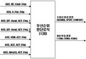
또한, 상기 우선순위 판단 로직부는 상기 페일 세이프 판단 로직부, 상기 불균일 노면 추정 로직부, 상기 차량통합제어장치 동작 판단 로직부, 상기 급 가/감속 판단 로직부, 상기 노면 마찰력 추정 로직부로부터 입력받은 신호들을, B급/C급 능동제어장치 결함 신호, A급 능동제어장치 결함 신호, 제1 불균일 노면 판단 신호, 제2 불균일 노면 판단 신호, 능동제어장치의 작동 신호, 급가속 또는 급감속 상태에 따른 능동제어장치 작동 신호, 저마찰 또는 고마찰 도로 판단신호 순으로 처리하는 것을 특징으로 하는 전동식 조향 장치의 프릭션 조절 장치를 제공한다.The priority determination logic unit may receive the input from the fail safe determination logic unit, the non-uniform road surface estimation logic unit, the vehicle integrated controller operation determination logic unit, the acceleration / deceleration determination logic unit, and the road surface friction estimation logic unit The signals are classified into the B class / C class active control device fault signal, the class A active control device fault signal, the first uneven road surface judgment signal, the second uneven road surface judgment signal, the active control device operation signal, And a low friction or high friction road judging signal in accordance with the operation of the control unit.
또한, 상기 능동제어장치 제어부는 B급/C급 능동제어장치 결함 신호, 저마찰 또는 고마찰 도로 판단신호를 입력 받으면, 상기 능동제어장치의 지지력을 기설정된 제3 지지력 값으로 조절하는 신호를 출력하고, A급 능동제어장치 결함 신호, 제2 불균일 노면 판단 신호, 능동제어장치의 작동신호, 급가속 또는 급감속 상태에 따른 능동제어장치의 작동 신호를 입력 받으면, 상기 능동제어장치의 지지력을 기설정된 제1 지지력 값으로 조절하는 신호를 출력하며, 제1 불균일 노면 판단 신호를 입력 받으면, 상기 능동제어장치의 지지력을 기설정된 제2 지지력 값으로 조절하는 신호를 출력하는 것을 특징으로 하는 전동식 조향 장치의 프릭션 조절 장치를 제공한다.When the active control device controller receives the defect class B / C-level active control device failure signal, the low friction or the high friction road determination signal, it outputs a signal for adjusting the bearing force of the active control device to a predetermined third bearing force value And receives an activation signal of the active control device in accordance with a class A active control device fault signal, a second uneven road surface determination signal, an active control device operation signal, or a rapid acceleration or deceleration / deceleration state, And outputs a signal for adjusting the bearing capacity of the active control device to a predetermined second storage capacity value when receiving the first uneven road surface determination signal. And a friction control device of the present invention.
또한, 상기 제1 지지력 값은 45 뉴턴미터이고, 상기 제2 지지력 값은 30 뉴턴미터이며, 상기 제3 지지력 값은 15 뉴턴미터인 것을 특징으로 하는 전동식 조향 장치의 프릭션 조절 장치를 제공한다.The first bearing force value is 45 Newton meters, the second bearing force value is 30 Newton meters, and the third bearing force value is 15 Newton meters.
이상에서 설명한 바와 같이 본 발명에 따른 전동식 조향 장치의 프릭션 조절 방법은 차량이 주행하는 노면 상황이나 주행 환경을 반영하여 전동식 조향 장치의 조타감을 구현할 수 있는 효과가 있다.
As described above, the friction adjustment method of the electric power steering system according to the present invention has an effect of realizing a sense of steering of the electric power steering system by reflecting the road surface or the traveling environment on which the vehicle is traveling.
도면 1도는 본 발명의 바람직한 실시예에 따른 전동식 조향 장치의 프릭션 조절 방법이 적용되는 기본 개념 및 기본 구성을 보여주는 도면이다.
도면 2도는 본 발명의 바람직한 실시예에 따른 전동식 조향 장치의 프릭션 조절 방법의 전동식 조향 장치 제어 로직부의 내부 구성을 블럭으로 보여주는 도면이다.
도면 3도는 본 발명의 바람직한 실시예에 따른 전동식 조향 장치의 프릭션 조절 방법이 적용되는 전동식 조향 장치를 보여주는 도면이다.
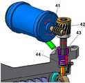
도면 4도는 도면 3도의 'A'부분을 확대하여 도시한 도면이다.
도면 5도는 본 발명의 바람직한 실시예에 따른 전동식 조향 장치의 프릭션 조절 방법에서 전동식 조향 장치의 프릭션이 조절되는 과정을 보여주는 도면이다.
도면 6도는 본 발명의 바람직한 실시예에 따른 전동식 조향 장치의 프릭션 조절 방법에서 최적 조향감을 달성하기 위한 능동 제어 장치의 지지력 변경의 값들을 보여주는 도면이다.
도면 7도는 본 발명의 바람직한 실시예에 따른 전동식 조향 장치의 프릭션 조절 장치의 내부 구성을 보다 자세하게 보여주는 도면이다.
도면 8도는 본 발명의 바람직한 실시예에 따른 전동식 조향 장치의 프릭션 조절 장치의 페일 세이프 판단 로직부의 작동과정을 보여주는 도면이다.
도면 9도는 페일 세이프 판단 로직부가 전동식 조향 장치에서 발생된 오류의 경중을 판단하는 과정을 보여주는 순서도이다.
도면 10도는 본 발명의 바람직한 실시예에 따른 전동식 조향 장치의 프릭션 조절 방법에서 온로드 노면을 추정하는 방법을 간략하게 보여주는 도면이다.
도면 11도는 본 발명의 바람직한 실시예에 따른 전동식 조향 장치의 프릭션 조절 방법에서 불균일 노면을 추정하는 방법을 간략하게 보여주는 도면이다.
도면 12도는 본 발명의 바람직한 실시예에 따른 불균일 노면 추정 로직부의 입력과 출력의 값을 보여주는 블럭도이다.
도면 13도는 본 발명의 바람직한 실시예에 따른 불균일 노면 추정 로직부가 노면의 상태를 판단하는 과정을 보여주는 순서도이다.
도면 14도는 본 발명의 바람직한 실시예에 따른 차량통합제어장치 동작 판단 로직부의 입출력 신호를 보여주는 블럭도이다.
도면 15도는 이러한 차량통합제어장치 동작 판단 로직부의 작동과정을 보여주는 순서도이다.
도면 16도는 본 발명의 바람직한 실시예에 따른 전동식 조향 장치의 프릭션 조절 방법에서 차량의 급가속 또는 급감속을 판단하는 과정을 보여주는 도면이다.
도면 17도는 본 발명의 바람직한 실시예에 따른 전동식 조향 장치의 프릭션 조절 방법에서 차량의 급가속 또는 급감속을 판단하는 과정을 순서도로 보여주는 도면이다.
도면 18도는 노면 마찰력을 추정하는 로직을 보여주는 도면이다.
도면 19도는 도면 18도의 과정을 순서도로 정리하여 보여주는 도면이다.
도면 20도는 본 발명의 바람직한 실시예에 따른 우선순위 판단 로직부에서 입출력 신호를 보여주는 도면이다.
도면 21도는 이러한 우선순위 판단 로직부에서 각 신호의 우선 순위를 판단하는 과정을 보여준다.FIG. 1 is a view showing a basic concept and a basic configuration to which a friction adjustment method of an electric power steering apparatus according to a preferred embodiment of the present invention is applied.
FIG. 2 is a block diagram showing an internal configuration of an electric steering control logic unit of a friction control method of an electric steering system according to a preferred embodiment of the present invention; FIG.
FIG. 3 is a view showing an electric power steering apparatus to which a friction control method of an electric power steering apparatus according to a preferred embodiment of the present invention is applied.
And FIG. 4 is an enlarged view of the 'A' portion of FIG. 3.
FIG. 5 is a view illustrating a process of adjusting the friction of the electric-powered steering apparatus in the friction adjusting method of the electric-powered steering apparatus according to the preferred embodiment of the present invention.
FIG. 6 is a view showing values of bearing capacity change of an active control device for achieving optimum steering feeling in a friction control method of an electric power steering according to a preferred embodiment of the present invention.
7 is a view showing in detail the internal structure of the friction adjusting device of the electric power steering apparatus according to the preferred embodiment of the present invention.
FIG. 8 is a flowchart illustrating an operation of the fail safe decision logic unit of the frictional adjustment device of the electric power steering apparatus according to the preferred embodiment of the present invention.
9 is a flowchart showing a process of determining the severity of an error generated in the electric power steering apparatus by the fail safe decision logic unit.
FIG. 10 is a schematic view illustrating a method of estimating an on-road road surface in a friction control method of an electric-powered steering apparatus according to a preferred embodiment of the present invention.
FIG. 11 is a schematic view illustrating a method for estimating a non-uniform road surface in a friction control method of an electric power steering apparatus according to a preferred embodiment of the present invention.
12 is a block diagram showing input and output values of a non-uniform road surface estimation logic unit according to a preferred embodiment of the present invention.
FIG. 13 is a flowchart illustrating a process of determining a state of a road surface by a non-uniform road surface estimation logic according to a preferred embodiment of the present invention.
FIG. 14 is a block diagram showing input / output signals of a vehicle integrated control apparatus operation determination logic unit according to a preferred embodiment of the present invention.
FIG. 15 is a flowchart showing the operation process of the vehicle integrated control unit operation determination logic unit.
FIG. 16 is a diagram illustrating a process of determining rapid acceleration or deceleration of a vehicle in a friction control method of an electric power steering according to a preferred embodiment of the present invention.
FIG. 17 is a flowchart illustrating a process of determining rapid acceleration or deceleration of a vehicle in a friction control method of an electric power steering according to a preferred embodiment of the present invention.
18 is a view showing logic for estimating the road surface friction force.
FIG. 19 is a flowchart showing the process of FIG. 18 in a flowchart.
20 is a diagram showing input / output signals in a priority determination logic unit according to a preferred embodiment of the present invention.
FIG. 21 shows the process of determining the priority of each signal in the priority decision logic section.
이하, 첨부한 도면을 참조하여 본 발명의 실시예들에 대해 상세히 설명한다. 본 발명은 다양한 변경을 가할 수 있고 여러 가지 형태를 가질 수 있는 바, 특정 실시예들은 도면에 예시하고 본문에 상세하게 설명하고자 한다. 그러나, 이는 본 발명을 특정한 개시 형태에 대해 한정하려는 것이 아니며, 본 발명의 사상 및 기술 범위에 포함되는 모든 변경, 균등물 내지 대체물을 포함하는 것으로 이해되어야 한다.Hereinafter, embodiments of the present invention will be described in detail with reference to the accompanying drawings. While the invention is susceptible to various modifications and alternative forms, specific embodiments thereof are shown by way of example in the drawings and are herein described in detail. It should be understood, however, that the invention is not intended to be limited to the particular forms disclosed, but includes all modifications, equivalents, and alternatives falling within the spirit and scope of the invention.
도면 1도는 본 발명의 바람직한 실시예에 따른 전동식 조향 장치의 프릭션 조절 방법이 적용되는 기본 개념 및 기본 구성을 보여주는 도면이다.FIG. 1 is a view showing a basic concept and a basic configuration to which a friction adjustment method of an electric power steering apparatus according to a preferred embodiment of the present invention is applied.
본 발명의 바람직한 실시예에 따른 전동식 조향 장치의 프릭션 조절 장치는 차량(10)에 장착되는 전동식 조향 장치(20)의 능동 제어 장치(40)의 조절을 통하여 전동식 조향 장치(20)의 조타감을 조절할 수 있다.The frictional adjustment device of the electric power steering system according to the preferred embodiment of the present invention is configured to adjust the steering feel of the
그리고, 이를 위하여 본 발명의 바람직한 실시예에 따른 전동식 조향 장치의 프릭션 조절 방법은 전동식 조향 장치 제어 로직부(100)가 능동 제어 장치 조절기(30)에 인가하는 신호를 조절하여 노면 상황에 따라 알맞은 조향감을 제공할 수 있다.For this purpose, the frictional adjustment method of the electric power steering system according to the preferred embodiment of the present invention adjusts the signal applied to the active
도면 2도는 본 발명의 바람직한 실시예에 따른 전동식 조향 장치의 프릭션 조절 방법의 전동식 조향 장치 제어 로직부(100)의 내부 구성을 블럭으로 보여주는 도면이다.2 is a block diagram showing an internal configuration of an electric steering
본 발명의 바람직한 실시예에 따른 전동식 조향 장치 제어 로직부(100)는 전동식 조향 장치(20)의 이씨유(21) 등에 프로그램적으로 구성될 수 있다.The electric power steering
본 발명의 바람직한 실시예에 따른 전동식 조향 장치 제어 로직부(100)는 외부 신호 로직부(111), 내부 신호 로직부(112), 페일-세이프 판단 로직부(121), 불균일 노면 추정 로직부(122), 차량통합제어장치 동작 판단 로직부(123), 급 가감속 판단 로직부(124), 노면 마찰력 추정 로직부(125), 우선 순위 판단 로직부(130), 조향감 제어 로직부(141), 능동제어장치 제어 로직부(142)를 포함하여 구성될 수 있다.The electric power steering
본 발명의 바람직한 실시예에 따른 전동식 조향 장치 제어 로직부(100)는 외부 신호 로직부(111)를 통하여 차량(10)의 휠 속도, 차속을 입력받을 수 있다. 또한, 내부 신호 처리 로직부(112)를 통하여 Q축 전류, 조향각, 컬럼 토크, 조향각 속도를 입력받을 수 있다.The electric steering
그리고, 이러한 입력 신호를 바탕으로 차량(10)이 주행하는 도로의 상황 등을 파악하여 전동식 조향 장치(20)의 조향감을 조절할 수 있다.Based on the input signals, the steering feeling of the electric-powered
전동식 조향 장치 제어 로직부(100)는 외부 신호 로직부(111)와 내부 신호 처리 로직부(112)를 통하여 입력된 값을 통하여 산출된 값을 조향감 변경 로직(151)과 캔 통신 로직부(152)에 인가하고, 이를 통하여 전동식 조향 장치(20)의 능동 제어 장치(40)를 조절하여 노면 상황에 따른 조향감을 구현할 수 있다.The electric steering system
도면 3도는 본 발명의 바람직한 실시예에 따른 전동식 조향 장치의 프릭션 조절 방법이 적용되는 전동식 조향 장치(20)를 보여주는 도면이다.FIG. 3 is a view showing an electric
본 발명의 바람직한 실시예에 따른 전동식 조향 장치의 프릭션 조절 방법은 전동식 조향 장치(20)에 구비된 능동 제어 장치(40)의 지지력 변화를 통하여 전동식 조향 장치(20)가 전달하는 조향감을 조절할 수 있다.The frictional adjustment method of the electric power steering apparatus according to the preferred embodiment of the present invention can adjust the steering feeling transmitted from the electric
도면 4도는 도면 3도의 'A'부분을 확대하여 도시한 도면이다.And FIG. 4 is an enlarged view of the 'A' portion of FIG. 3.
본 발명의 바람직한 실시예에 따른 전동식 조향 장치의 프릭션 조절 방법이 적용되는 능동 제어 장치(40)는 모터 샤프트인 웜(41), 웜 휠(42), 플러그(43), 스프링(44)를 포함하여 구성될 수 있다. 즉, 웜(41)의 시계방향 또는 반시계 방향의 회전을 통하여 감속비가 15 : 1로 구현된 웜 휠(42)을 돌리고, 이에 따라 스프링(44)의 압축이 조절됨으로써, 능동 제어 장치(40)의 지지력이 15 뉴턴미터(Nm) 내지 45 뉴턴미터까지 조절될 수 있다.The
도면 5도는 본 발명의 바람직한 실시예에 따른 전동식 조향 장치의 프릭션 조절 방법에서 전동식 조향 장치(20)의 프릭션이 조절되는 과정을 보여주는 도면이다.FIG. 5 is a view showing a process of adjusting the friction of the electric
본 발명의 바람직한 실시예에 따른 전동식 조향 장치(20)는 먼저 능동 제어 장치(40)를 조절하는 명령을 받을 수 있다.(S5-1)The
그리고, 이러한 명령에 따라 모터가 회전하고(S5-2), 모터가 회전함에 따라 웜(41)도 따라서 회전(S5-3)하여 능동 제어 장치(40)의 웜 휠(42)이 회전하게 된다.(S5-4)As the motor rotates (S5-2) according to the command, the
그리고, 플러그(43)이 회전(S5-5)하여 스프링(44)을 압축(S5-6)하고, 이러한 스프링(44)의 압축에 따라 전동식 조향 장치(20)의 프릭션이 변경되게 되는 것이다.(S5-7)Then, the
또한, 본 발명의 바람직한 실시예에 따른 전동식 조향 장치의 프릭션 조절 방법에서 전동식 조향 장치(20)의 조향감이 조절된다는 것은 프릭션, 즉 마찰감이 변경된다는 의미와 동일한 의미로 사용될 수 있다.In addition, in the friction adjusting method of the electric power steering system according to the preferred embodiment of the present invention, the steering feeling of the
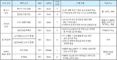
도면 6도는 본 발명의 바람직한 실시예에 따른 전동식 조향 장치의 프릭션 조절 방법에서 최적 조향감을 달성하기 위한 능동 제어 장치(40)의 지지력 변경의 값들을 보여주는 도면이다.6 is a view showing values of bearing capacity change of the
본 발명의 바람직한 실시예에 따른 전동식 조향 장치의 프릭션 조절 방법은 노면이 불균일한 구간은 불균일 수준이 높은 노면과 불균일 수준이 낮은 노면으로 분류할 수 있다. 그리고, 불균일 수준이 낮은 노면은 제1 불균일 노면으로, 불균일 수준이 높은 노면은 제2 불균일 노면으로 분류될 수 있다.The friction control method of the electric power steering according to the preferred embodiment of the present invention can be classified into a road surface having a high level of unevenness and a road surface having a low level of unevenness. The road surface having a low level of nonuniformity may be classified as a first nonuniform road surface, and the road surface having a high level of nonuniformity level may be classified as a second nonuniform road surface.
이렇게 분류된 불균일 노면에서는 노면 킥백을 저감하기 위하여 높은 프릭션이 필요하고, 주행 안정성을 향상시키기 위하여 무거운 조타감이 필요하다.In this sort of uneven road surface, high friction is required to reduce the kickback on the road, and heavy steering feeling is needed to improve the driving stability.
따라서, 본 발명의 바람직한 실시예에 따른 전동식 조향 장치의 프릭션 조절 방법은 차량(10)의 휠 스피드와 차속을 입력받아서, 능동 제어 장치(40)의 지지력을 조절할 수 있으며, 구체적으로 불균일 수준이 높은 노면에서는 능동 제어 장치(40)의 지지력을 45 뉴턴미터로, 불균일 수준이 낮은 노면에서는 능동 제어 장치(40)의 지지력을 30 뉴턴미터로 조절할 수 있다.Accordingly, the frictional adjustment method of the electric-powered steering apparatus according to the preferred embodiment of the present invention can adjust the support force of the
또한, 본 발명의 바람직한 실시예에 따른 전동식 조향 장치의 프릭션 조절 방법은 노면의 상태가 저마찰 도로로 판단한 경우에는, 전동식 조향 장치(20)의 조향감의 프릭션을 낮추어서 복원성을 향상시키도록 제어할 수 있다. 즉, 컬럼토크, 전동식 조향 장치(20)의 출력 등을 입력받아서 능동 제어 장치(40)의 지지력을 15 뉴턴미터로 조절할 수 있다.In the friction control method of the electric power steering system according to the preferred embodiment of the present invention, when the state of the road surface is determined to be a low friction road, the frictional feeling of the
본 발명의 바람직한 실시예에 따른 전동식 조향 장치의 프릭션 조절 방법은 또한, 차량의 차량통합제어장치의 동작신호를 감지하여 차량에 슬립이 발생되었는지 여부를 판단할 수 있다.The frictional adjustment method of the electric-powered steering apparatus according to the preferred embodiment of the present invention can also detect an occurrence of a slip in the vehicle by sensing an operation signal of the integrated vehicle control system of the vehicle.
그리고, 슬립이 발생하면 운전자의 오조타 방지를 위하여 높은 프릭션 및 무거운 조타감이 필요하므로 능동 제어 장치(40)의 지지력을 45 뉴턴미터로 조절하는 과정을 수행할 수 있다.If a slip occurs, a high friction and a heavy steering feeling are required to prevent the driver from misrecognizing the driver, so that the supporting force of the
그 이외에도, 본 발명의 바람직한 실시예에 따른 전동식 조향 장치의 프릭션 조절 방법은 차량의 급가속이나 급감속을 감지하여 조향감을 변경할 수 있다. 즉 급가속이나 급감속시에는 토크 및 제동 스티어의 쏠림 현상을 방지하기 위하여 높은 프릭션과 무거운 조타감이 필요하기 때문에 능동 제어 장치(40)의 지지력을 45 뉴턴미터로 조절하는 과정을 수행할 수 있다.In addition, the friction adjustment method of the electric power steering apparatus according to the preferred embodiment of the present invention can change the steering feeling by detecting rapid acceleration or deceleration of the vehicle. That is, in order to prevent the torque and braking steer from leaning during rapid acceleration or deceleration, a high friction and a heavy steering feeling are required, so that the supporting force of the
또한, 본 발명의 바람직한 실시예에 따른 전동식 조향 장치의 프릭션 조절 방법은 전동식 조향 장치(20)의 오류가 나는 상황을 감지하여, 각 레벨별로 다른 조향감을 줄수록 능동 제어 장치(40)의 지지력을 조절할 수 있다. 예를 들어, A급 오류인 경우에는 45 뉴턴미터로 지지력을 조절할 수 있고, B급이나 C급 오류인 경우에는 15 뉴턴미터로 지지력을 변경할 수 있다.The frictional adjustment method of the electric power steering apparatus according to the preferred embodiment of the present invention detects an error condition of the
그리고, 앞서 살펴본 바와 같이 본 발명의 바람직한 실시예에 따른 전동식 조향 장치의 프릭션 조절 방법은 능동 제어 장치(40)의 조절되는 각각의 지지력을 기설정된 제1 지지력, 제2 지지력, 제3 지지력이라고 지칭할 수 있으며, 제1 지지력은 45 뉴턴미터를, 제2 지지력은 30 뉴턴미터를, 제3 지지력은 15 뉴턴미터를 가리키는 것일 수 있다. 그러나, 이에 한정되는 것은 아니고, 본 발명의 바람직한 실시예에 따라서 적절한 값이 선택될 수 있다.As described above, the friction control method of the electric power steering apparatus according to the preferred embodiment of the present invention is characterized in that each controlled support force of the
도면 7도는 본 발명의 바람직한 실시예에 따른 전동식 조향 장치의 프릭션 조절 장치의 내부 구성을 보다 자세하게 보여주는 도면이다.7 is a view showing in detail the internal structure of the friction adjusting device of the electric power steering apparatus according to the preferred embodiment of the present invention.
이하, 각 구성을 하나하나씩 자세히 살펴보면 다음과 같다.Hereinafter, each configuration will be described in detail as follows.
도면 8도는 본 발명의 바람직한 실시예에 따른 전동식 조향 장치의 프릭션 조절 장치의 페일 세이프 판단 로직부(121)의 작동과정을 보여주는 도면이다.8 is a diagram illustrating an operation process of the fail safe
본 발명의 바람직한 실시예에 따른 전동식 조향 장치의 프릭션 조절 장치의 페일 세이프 판단 로직부(121)는 전동식 조향 장치(20)의 내부 정보(Fault_signal)를 입력받아, 전동식 조향 장치(20)에 현재 오류가 났는지 여부를 판단할 수 있다.The fail safe
이를 위하여, 페일 세이프 판단 로직부(121)는 전동식 조향 장치(20)로부터 오류 신호를 입력받아서, 그 경중을 판단하여 A급 오류신호(ARS_A_Fault_Flag) 또는 B급이나 C급 오류신호(ARS_BC_Fault_Flag)를 송출할 수 있다.To this end, the fail safe
도면 9도는 페일 세이프 판단 로직부(121)가 전동식 조향 장치(20)에서 발생된 오류의 경중을 판단하는 과정을 보여주는 순서도이다.9 is a flowchart showing a process of determining the severity of an error generated in the electric-powered
본 발명의 바람직한 실시예에 따른 페일 세이프 판단 로직부(121)는 전동식 조향 장치(20)의 조향각 이상이나, 배터리 저전압, 배터리 고전압 또는 A급 오류의 경우(S9-1)에는 A급 오류 신호를 내보낼 수 있다.(S9-3)The fail safe
그러나, 이러한 조건을 만족하지 않으면, B급 또는 C급 오류인지 확인(S9-2)하고 B급 또는 C급 오류신호를 송출(S9-4)할 수 있으며, 이에 해당되지 않는 경우에는 오류신호를 클리어하는 작업을 수행할 수 있다.(S9-5)However, if these conditions are not satisfied, it is possible to check whether the error is a B-class or C-class error (S9-2) and send a B-class or C-class error signal (S9-4) It is possible to perform the operation of clearing (S9-5)
도면 10도와 11도는 본 발명의 바람직한 실시예에 따른 전동식 조향 장치의 프릭션 조절 방법에서 불균일 노면을 추정하는 방법을 간략하게 보여주는 도면이다.FIGS. 10 and 11 schematically illustrate a method of estimating a non-uniform road surface in a friction control method of an electric power steering apparatus according to a preferred embodiment of the present invention.
먼저, 도면 10도는 온 로드(on road)에서의 휠 스피드 값과 순간 변화 적분량을 보여주는 도면이다.First, FIG. 10 is a diagram showing wheel speed values and instantaneous amounts on the road.
포장도로를 주행하는 경우에는 휠 스피드의 순간 변화량이 작고, 순간 변화에 대한 적분량의 값도 매우 적은 값인 것일 확인할 수 있다.It can be confirmed that the momentary variation of the wheel speed is small when the vehicle runs on a paved road and the value of the integral with respect to the instantaneous change is also a very small value.
하지만, 이와 달리, 오프로드(off road)를 주행하는 경우, 휠 스피드와 순간 변화 적분량은 매우 큰 값으로 나타나게 된다.On the other hand, when driving off-road, the wheel speed and the instantaneous change amount become very large values.
따라서, 본 발명의 바람직한 실시예에 따른 전동식 조향 장치의 프릭션 조절 방법은 이러한 현상을 확인하여 현재 차량이 불균일 노면을 주행하고 있는지 여부를 판단할 수 있다.Therefore, in the friction adjusting method of the electric power steering apparatus according to the preferred embodiment of the present invention, it is possible to confirm whether or not the present vehicle is traveling on a non-uniform road surface.
도면 12도는 본 발명의 바람직한 실시예에 따른 불균일 노면 추정 로직부(122)의 입력과 출력의 값을 보여주는 블럭도이다.12 is a block diagram showing input and output values of a non-uniform road surface
본 발명의 바람직한 실시예에 따른 불균일 노면 추정 로직부(122)는 각 타이어의 휠 신호(Wheel_Speed)와 불균일 노면 프로파일 신호(Territory_type_threshold)값을 입력받아서, 현재 노면이 작게 불규칙한지, 크게 불규칙한지 여부를 판단한 신호를 송출할 수 있다.The uneven road
도면 13도는 본 발명의 바람직한 실시예에 따른 불균일 노면 추정 로직부(122)가 노면의 상태를 판단하는 과정을 보여주는 순서도이다.FIG. 13 is a flowchart illustrating a process for determining a state of a road surface by the non-uniform road surface
먼저, 본 발명의 바람직한 실시예에 따른 불균일 노면 추정 로직부(122)는 좌우 타이어의 휠 스피드 값을 입력받아 그 차이값(Var_Territory_output)을 계산하여 이 값을 기설정된 프로파일 값과 비교하는 과정을 거칠 수 있다(S13-1). 그리고, 여기서 기설정된 프로파일 값이란 제1 불균일 기준치(ARS_Terr_Type_Threshold_1)와 제2 불균일 기준치(ARS_Terr_Type_Threshold_2)로 지칭될 수 있으며, 이러한 불균일 기준치는 맵으로 만들어져 이미 저장되어 있을 수 있다.First, the uneven road surface
좌우 타이어의 휠 스피드의 차이가 기설정된 제1 불균일 기준치보다 크고, 제2 불균일 기준치보다 작다면, 노면이 작게 불규칙하다는 신호(ARS_OFF_Road_ACT_Flag_1)가 출력될 수 있다.(S13-3)If the difference between the wheel speeds of the left and right tires is greater than the predetermined first non-uniformity reference value and smaller than the second non-uniform reference value, a signal ARS_OFF_Road_ACT_Flag_1 indicating that the road surface is small and irregular may be output (S13-3)
또한, 좌우 휠 스피드의 차이가 제2 불균일 기준치보다 크다면(S13-2), 본 발명의 바람직한 실시예에 따른 불균일 노면 추정 로직부(122)는 노면이 크게 불규칙하다는 신호(ARS_OFF_Road_ACT_Flag_2)를 출력할 수 있다.(S13-4)If the difference between the left and right wheel speeds is larger than the second non-uniformity reference value (S13-2), the non-uniform road surface
그러나, 제1 불균일 기준치보다 낮은 값이라면, 노면이 불균일하지 않은 것으로 판단되어, 모든 신호가 리셋되는 과정을 거칠 수 있다.(S13-5)However, if the value is lower than the first non-uniformity reference value, it is determined that the road surface is not uneven, and all signals are reset. (S13-5)
도면 14도는 본 발명의 바람직한 실시예에 따른 차량통합제어장치 동작 판단 로직부(123)의 입출력 신호를 보여주는 블럭도이다.14 is a block diagram showing an input / output signal of the integrated vehicle controller operation decision logic unit 123 according to the preferred embodiment of the present invention.
본 발명의 바람직한 실시예에 따른 전동식 조향 장치의 프릭션 조절 방법의 차량통합제어장치 동작 판단 로직부(123)는 차량통합제어장치의 작동 유무 신호(CF_ESC_ACT)를 입력받아, 능동 제어 장치(40)의 작동 여부 신호(ARS_VSM_ACT_Flag)를 송출할 수 있다.The vehicle integrated control device operation determination logic unit 123 of the frictional adjustment method of the electric steering system according to the preferred embodiment of the present invention receives the operational presence / absence signal CF_ESC_ACT of the integrated vehicle control system, (ARS_VSM_ACT_Flag) can be transmitted.
도면 15도는 이러한 차량통합제어장치 동작 판단 로직부(123)의 작동과정을 보여주는 순서도이다.FIG. 15 is a flow chart showing the operation of the vehicle integrated controller operation determination logic unit 123.
먼저, 본 발명의 바람직한 실시예에 따른 차량통합제어장치 동작 판단 로직부(123)는 차량통합제어장치의 동작 신호를 입력받을 수 있다.(S15-1)First, the vehicle integrated control apparatus operation determination logic unit 123 according to the preferred embodiment of the present invention may receive an operation signal of the integrated vehicle control apparatus. (S15-1)
그리고, 차량통합제어장치의 동작 여부를 확인하여(S15-2), 차량통합제어장치가 작동하면 마찰력 작동 신호(ARS_VSM_ACT_Flag)를 송출할 수 있고(S15-3), 차량통합제어장치가 작동하지 않으면 능동 제어 장치(40)를 작동시키지 않도록 내보내는 신호를 클리어할 수 있다.(S15-4)Then, it is confirmed whether or not the integrated vehicle control apparatus is operated (S15-2). If the integrated vehicle control apparatus is operated, a frictional force operation signal (ARS_VSM_ACT_Flag) can be transmitted (S15-3). If the integrated vehicle control apparatus is not operated It is possible to clear the signal to be outputted so as not to activate the
도면 16도는 본 발명의 바람직한 실시예에 따른 전동식 조향 장치의 프릭션 조절 방법에서 차량의 급가속 또는 급감속을 판단하는 과정을 보여주는 도면이다.FIG. 16 is a diagram illustrating a process of determining rapid acceleration or deceleration of a vehicle in a friction control method of an electric power steering according to a preferred embodiment of the present invention.
본 발명의 바람직한 실시예에 따른 전동식 조향 장치의 프릭션 조절 장치의 급 가/감속 판단 로직부(124)는 차량의 차속을 미분하여 급가속 또는 급감속을 판단할 수 있다.The acceleration / deceleration decision logic unit 124 of the frictional adjustment device of the electric-powered steering apparatus according to the preferred embodiment of the present invention can discriminate a rapid acceleration or deceleration by differentiating the vehicle speed of the vehicle.
도면 17도는 본 발명의 바람직한 실시예에 따른 전동식 조향 장치의 프릭션 조절 방법에서 차량의 급가속 또는 급감속을 판단하는 과정을 순서도로 보여주는 도면이다.FIG. 17 is a flowchart illustrating a process of determining rapid acceleration or deceleration of a vehicle in a friction control method of an electric power steering according to a preferred embodiment of the present invention.
먼저, 본 발명의 바람직한 실시예에 따른 급 가/감속 판단 로직부(124)는 차속을 입력받는 과정을 거칠 수 있다.(S17-1)First, the acceleration / deceleration decision logic unit 124 according to the preferred embodiment of the present invention may be operated to receive a vehicle speed (S17-1)
그리고, 입력받은 속도를 엠피에스(mps) 단위계로 변환하는 과정을 거칠 수 있다.(S17-2)Then, the input speed may be converted into an MPS system (S17-2)
그리고, 이러한 속도를 미분하여 가속도를 계산하고(S17-3), 이를 저역통과 필터를 거쳐서 필터링(S17-4)한 이후에, 이러한 가속도 값(Filtered_Vehicle_Acc)이 기설정된 일정 가속도(Upper_Threshod) 이상인지, 기설정된 일정 감속도 이상(Lower_Threshold)이상인지 판단되는 과정을 거칠 수 있다.(S17-5)Then, after calculating the acceleration by differentiating the speed (S17-3) and filtering it through a low-pass filter (S17-4), it is determined whether the acceleration value (Filtered_Vehicle_Acc) is equal to or more than a predetermined constant acceleration (Upper_threshod) It may be determined whether it is equal to or higher than a preset constant deceleration (Lower_Threshold) (S17-5)
그리고, 기설정된 일정 가속도 또는 일정 감속도 이상으로 판단되는 경우, 현재 차량이 급가감속 상태라고 판단하고, 능동 제어 장치(40) 작동 신호(ARS_ACC_ACT_Flag)를 송출할 수 있다.(S17-6) 그리고, 급가감속이 아니라고 판단되는 경우에는 이를 클리어할 수 있다.If it is determined that the vehicle is in the rapid acceleration / deceleration state, the
도면 18도는 노면 마찰력을 추정하는 로직을 보여주는 도면이다.18 is a view showing logic for estimating the road surface friction force.
구체적으로 본 발명의 바람직한 실시예에 따른 전동식 조향 장치의 프릭션 조절 방법의 노면 마찰력 추정 로직부(125)는 타이어의 마찰력에 대한 변화를 전동식 조향 장치(20)의 토크 신호의 변화율과 비교하여, 실제 아스팔트 기준로의 토크 변화율을 맵핑한 결과를 기준 맵핑치로 하여, 그 기준값보다 이하인 경우에는 능동 제어 장치(40)의 마찰력을 증가시켜 차량의 조종 안정성을 향상시킬 수 있다.Specifically, the road surface friction estimation logic unit 125 of the frictional adjustment method of the electric-powered steering apparatus according to the preferred embodiment of the present invention compares the change in the friction force of the tire with the rate of change of the torque signal of the electric- The result of mapping the rate of change of the torque on the actual asphalt reference is regarded as a reference value. If the reference value is less than the reference value, the frictional force of the
도면 19도는 도면 18도의 과정을 순서도로 정리하여 보여주는 도면이다.FIG. 19 is a flowchart showing the process of FIG. 18 in a flowchart.
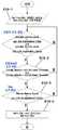
먼저, 본 발명의 바람직한 실시예에 따른 노면 마찰력 추정 로직부(125)는 레퍼런스 추정값(Ref_Total_dist)와 차량 부하값(Real_Total_Dist)를 입력받는 과정을 거칠 수 있다.(S19-1)First, the road surface friction estimation logic unit 125 according to the preferred embodiment of the present invention may receive a reference estimation value (Ref_Total_dist) and a vehicle load value (Real_Total_Dist). (S19-1)
그 다음으로 본 발명의 바람직한 실시예에 따른 노면 마찰력 추정 로직부(125)는 조향각(Absolute_Steering_Angle), 조향각속도(Column_Velocity), 차속(Filtered Vehicle Speed)을 입력받아서, 이를 각 기준값과 비교할 수 있다.Next, the road surface friction estimation logic unit 125 according to the preferred embodiment of the present invention receives the steering angle (Absolute_Steering_Angle), the steering angle velocity (Column_Velocity) and the vehicle speed (Vehicle Speed), and compares it with each reference value.
먼저, 조향각이 일정 조향각(ARS_2DB_Breakpoint_VTD) 범위에 있는지 판단되는 과정을 거칠 수 있다.(S19-2)First, it can be judged whether the steering angle is in the range of the constant steering angle (ARS_2DB_Breakpoint_VTD) (S19-2)
그리고, 조향각이 일정 조향각 범위에 있다면, 조향각속도가 일정 조향각속도 상하위 범위(ARS_CV_Upper_Threshold, ARS_CV_Lower_Threshold)를 넘는지 확인되는 과정을 거칠 수 있다.(S19-3)If the steering angle is within the predetermined steering angle range, it can be checked whether the steering angle speed exceeds the constant steering angle speed upper and lower range (ARS_CV_Upper_Threshold, ARS_CV_Lower_Threshold) (S19-3)
그 다음으로, 차속이 일정 차속(ARS_2DM_Breakpoints_VTD)을 넘는지 확인되는 과정을 거칠 수 있다.(S19-4)Next, it can be checked whether the vehicle speed exceeds the predetermined vehicle speed (ARS_2DM_Breakpoints_VTD) (S19-4)
이러한 모든 과정이 만족하면, 본 발명의 바람직한 실시예에 따른 노면 마찰력 추정 로직부(125)는 실제 토크값(Real_Totoal_Dist)를 레퍼런스 토크값(Ref_Total_Dist)로 나누어서 토크비(Ratio_Dist)를 구하는 과정을 거칠 수 있다.(S19-4) 그리고, 이 단계에서 토크비가 1보다 크면 고마찰로 판단하여 능동 제어 장치(40)의 마찰력을 미보상하고 토크비가 1보다 작으면 능동 제어 장치(40)의 마찰력을 보상하는 신호(ARS_AlignTq_ACT_Flag)를 송출할 수 있다.When all these processes are satisfied, the road surface friction estimation logic unit 125 according to the preferred embodiment of the present invention divides the actual torque value Real_Totoal_Dist by a reference torque value Ref_Total_Dist to obtain a torque ratio Ratio_Dist (S19-4). If the torque ratio is greater than 1, it is judged as high friction to compensate the frictional force of the
도면 20도는 본 발명의 바람직한 실시예에 따른 우선순위 판단 로직부(130)에서 입출력 신호를 보여주는 도면이다.FIG. 20 is a diagram showing input / output signals in the priority
본 발명의 바람직한 실시예에 따른 우선순위 판단 로직부(130)는 각 로직부에서 출력한 신호를 입력받아 조향감 변경 명령(Normal,Sport,Comport)과 능동 제어 장치(40) 변경 명령(15Nm, 30Nm, 45 Nm)을 송출할 수 있다.The priority
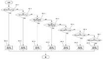
그리고, 도면 21도는 이러한 우선순위 판단 로직부(130)에서 각 신호의 우선 순위를 판단하는 과정을 보여준다.FIG. 21 shows a process of determining priority of each signal in the priority
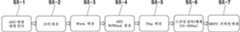
우선순위 판단 로직부(130)에 입력되는 신호 중에서, B급/C급 오류 신호가 가정 우선 순위가 높고(S21-1), 그 다음으로 A급 오류 신호(S21-2), 제1 불균일 노면 신호(S21-3), 제2 불균일 노면 신호(S21-4), 차량통합제어장치 작동 신호(S21-5), 급 가/감속 판단 신호(S21-6), 저마찰로 또는 고마찰로 판단 신호(S21-7) 순으로 판단하여 능동 제어 장치(40)의 지지력 및 조향감을 변경할 수 있다.(S21-8)Among the signals input to the priority
상술한 바와 같이, 본 발명의 바람직한 실시예들을 참조하여 설명하였지만 해당 기술 분야의 숙련된 당업자라면 하기의 특허 청구의 범위에 기재된 본 발명의 사상 및 영역으로부터 벗어나지 않는 범위 내에서 본 발명을 다양하게 수정 및 변경시킬 수 있음을 이해할 수 있을 것이다.
Although the preferred embodiments of the present invention have been disclosed for illustrative purposes, those skilled in the art will appreciate that various modifications, additions and substitutions are possible, without departing from the scope and spirit of the invention as disclosed in the accompanying claims. And changes may be made without departing from the spirit and scope of the invention.
10 : 차량
20 : 전동식 조향 장치
21 : 이씨유
30 : 능동 제어 장치 조절기
40 : 능동 제어 장치
100 : 전동식 조향 장치 제어 로직부
111 : 외부 신호 로직부
112 : 내부 신호 처리 로직부
121 : 페일 세이프 판단 로직부
122 : 불균일 노면 추정 로직부
123 : 차량통합제어장치 동작 판단 로직부
124 : 급 가/감속 판단 로직부
125 : 노면 마찰력 추정 로직부
130 : 우선순위 판단 로직부
141 : 조향감 변경 로직부
142 : 능동제어장치 제어 로직부
151 : 조향감 변경 로직부
152 : 캔 통신 로직부
(100)가10: Vehicle
20: Electric steering
21: Lee Seung Yu
30: active control device regulator
40: active control device
100: electric steering control logic section
111: External signal logic unit
112: internal signal processing logic unit
121: Fail-safe judgment logic unit
122: Non-uniform road surface estimation logic section
123: vehicle integrated control device operation determination logic unit
124: Rapid acceleration / deceleration decision logic section
125: road surface friction estimation logic unit
130: Priority determination logic unit
141: steering feeling change logic section
142: active control unit control logic unit
151: steering feeling change logic section
152: CAN communication logic section
(100)
Claims (17)
Translated fromKorean상기 차량의 휠 스피드 신호와 기저장된 불균일 노면 프로파일(profile) 신호를 입력받아 상기 차량이 주행하는 노면이 제1 불균일 노면인지, 제2 불균일 노면인지 여부를 판단하는 불균일 노면 추정 로직부;
차량통합제어장치의 작동 유무 신호를 입력받아 능동제어장치의 작동 여부를 결정하는 신호를 출력하는 차량통합제어장치 동작 판단 로직부;
상기 차량의 차속을 입력받아 능동제어장치의 작동 유무를 결정하는 신호를 출력하는 급 가/감속 판단 로직부;
상기 차량의 조향각, 조향각속도, 차속을 입력받아 상기 차량이 주행하는 노면이 저마찰 도로인지, 고마찰 도로인지 여부의 판단 신호를 출력하는 노면 마찰력 추정 로직부;
상기 페일 세이프 판단 로직부, 상기 불균일 노면 추정 로직부, 상기 차량통합제어장치 동작 판단 로직부, 상기 급 가/감속 판단 로직부, 상기 노면 마찰력 추정 로직부가 출력하는 신호들을 입력받아, 상기 신호들의 처리순서를 정하여 출력하는 우선순위 판단 로직부;
상기 우선순위 판단 로직부에서 출력하는 신호를 입력받아, 상기 전동식 조향 장치의 능동제어장치의 지지력을 조절하기 위한 신호를 출력하는 능동제어장치 제어부;를 포함하는 것을 특징으로 하는 전동식 조향 장치의 프릭션 조절 장치.
A fail safe judgment logic unit for receiving a fault signal from an electric steering system of a vehicle and outputting a class A active control unit fault signal or a class B / C active control unit fault signal;
A non-uniform road surface estimation logic unit receiving a wheel speed signal of the vehicle and a previously stored non-uniform road surface profile signal to determine whether the road surface on which the vehicle travels is a first non-uniform road surface or a second non-uniform road surface;
A vehicle integrated control device operation determination logic unit that receives a signal indicative of operation of the integrated vehicle control device and outputs a signal for determining whether the active control device operates;
Deceleration decision logic unit for receiving a vehicle speed of the vehicle and outputting a signal for determining whether the active control device is operated or not;
A road surface frictional force estimation logic unit that receives a steering angle, a steering angle speed, and a vehicle speed of the vehicle and outputs a signal indicating whether the road surface on which the vehicle travels is a low friction road or a high friction road;
The vehicle control system according to any one of claims 1 to 3, wherein the fail safe logic unit, the uneven road surface estimation logic unit, the integrated vehicle controller operation determination logic unit, the acceleration / deceleration decision logic unit, A priority determination logic unit for determining and outputting a sequence;
And an active control unit controller for receiving a signal output from the priority determination logic unit and outputting a signal for adjusting a supporting force of the active steering control device of the electric power steering system, Regulating device.
상기 페일 세이프 판단 로직부는
상기 차량의 전동식 조향 장치로부터 입력받은 신호가 조향각 이상, 배터리(battery) 저전압, 배터리 고전압 또는 레벨 에이(level A) 결함 신호를 나타내는 것이면 A급 능동제어장치 결함 신호를 출력하고,
상기 차량의 전동식 조향 장치로부터 입력받은 신호가 레벨 비 결함 신호 또는 레벨 씨(level b or level c) 결함 신호이면 B급/C급 능동제어장치 결함 신호를 출력하는 것을 특징으로 하는 전동식 조향 장치의 프릭션 조절 장치.
10. The method of claim 9,
The fail safe decision logic unit
Class A active control device fault signal if the signal received from the electric steering system of the vehicle indicates a steering angle error, a battery low voltage, a battery high voltage or a level A defect signal,
And a F / C-level active control device fault signal if the signal received from the electric steering system of the vehicle is a level non-defective signal or a level b or level c defective signal. .
상기 불균일 노면 추정 로직부는
상기 차량의 휠 스피드 신호를 입력받아, 좌우 휠 스피드 차이가 상기 불균일 노면 프로파일 신호로부터 추출된 기저장된 제1 불균일 기준치보다 크고 제2 불균일 기준치 보다 작으면 제1 불균일 노면으로 판단하고,
좌우 휠 스피드 차이가 제2 불균일 기준치 보다 크면 제2 불균일 노면으로 판단하는 것을 특징으로 하는 전동식 조향 장치의 프릭션 조절 장치.
10. The method of claim 9,
The non-uniform road surface estimation logic section
When the difference between the left and right wheel speeds is larger than a first non-uniform reference value stored beforehand extracted from the non-uniform road surface profile signal and smaller than a second non-uniform reference value,
And when the difference between the left and right wheel speeds is greater than the second non-uniformity reference value, the second non-uniform road surface is determined.
상기 차량통합제어장치 동작 판단 로직부는
상기 차량통합제어장치가 미작동하면 능동제어장치의 작동신호를 출력하지 않으며,
상기 차량통합제어장치가 작동하면 능동제어장치의 작동 신호를 출력하는 것을 특징으로 하는 전동식 조향 장치의 프릭션 조절 장치.
10. The method of claim 9,
The vehicle integrated controller operation determination logic unit
When the vehicle integrated control device is not operated, does not output an operation signal of the active control device,
And outputs an operation signal of the active control device when the vehicle integrated control device operates.
상기 차량의 차속을 입력받아 능동제어장치의 작동 유무를 결정하는 신호를 출력하는 급 가/감속 판단 로직부는
상기 차량의 차속이 기설정된 일정 가속도 이상이면 급가속으로 판단하고,
상기 차량의 차속이 기설정된 일정 감속도 이상이면 급감속으로 판단하여,
상기 차량이 급가속 또는 급감속 상태이면, 능동제어장치 작동 신호를 출력하는 것을 특징으로 하는 전동식 조향 장치의 프릭션 조절 장치.
10. The method of claim 9,
Deceleration decision logic unit which receives a vehicle speed of the vehicle and outputs a signal for determining the operation of the active control device
If the vehicle speed of the vehicle is equal to or greater than a predetermined constant acceleration,
If the vehicle speed of the vehicle is equal to or greater than a predetermined constant deceleration,
And outputs an active control device operation signal when the vehicle is in a rapid acceleration or deceleration state.
상기 노면 마찰력 추정 로직부는
상기 차량의 조향각이 기설정된 제1 조향값 이상이고, 상기 차량의 조향각이 기설정된 제2 조향값 이하이며,
상기 차량의 조향각속도가 기설정된 제1 조향각속도를 초과하고, 상기 차량의 조향각속도가 기설정된 제2 조향각속도 이하이고,
상기 차량의 차속이 기설정된 차속 이상이면;
상기 차량의 컬럼 토크 값을 기설정된 토크 값으로 나눈 값이 '1'보다 작으면 저마찰 도로 판단 신호를 출력하고,
상기 차량의 컬럼 토크 값을 기설정된 토크 값으로 나눈 값이 '1'보다 크면 고마찰 도로 판단 신호를 출력하는 것을 특징으로 하는 전동식 조향 장치의 프릭션 조절 장치.
10. The method of claim 9,
The road surface friction estimation logic unit
The steering angle of the vehicle is equal to or greater than a predetermined first steering value, the steering angle of the vehicle is equal to or less than a predetermined second steering value,
The steering angle of the vehicle exceeds a predetermined first steering angle velocity and the steering angle of the vehicle is less than a predetermined second steering angle velocity,
If the vehicle speed of the vehicle is not less than a predetermined vehicle speed;
When the value obtained by dividing the column torque value of the vehicle by the predetermined torque value is less than 1, the low friction road judging signal is outputted,
And outputs a high friction road judging signal if the value obtained by dividing the column torque value of the vehicle by the predetermined torque value is greater than 1.
상기 우선순위 판단 로직부는
상기 페일 세이프 판단 로직부, 상기 불균일 노면 추정 로직부, 상기 차량통합제어장치 동작 판단 로직부, 상기 급 가/감속 판단 로직부, 상기 노면 마찰력 추정 로직부로부터 입력받은 신호들을,
B급/C급 능동제어장치 결함 신호, A급 능동제어장치 결함 신호, 제1 불균일 노면 판단 신호, 제2 불균일 노면 판단 신호, 능동제어장치의 작동 신호, 급가속 또는 급감속 상태에 따른 능동제어장치 작동 신호, 저마찰 또는 고마찰 도로 판단신호 순으로 처리하는 것을 특징으로 하는 전동식 조향 장치의 프릭션 조절 장치.
10. The method of claim 9,
The priority determination logic unit
Wherein the signals received from the fail safe decision logic section, the non-uniform road surface estimation logic section, the vehicle integrated controller operation decision logic section, the acceleration / deceleration decision logic section and the road surface friction estimation logic section,
Class B / C class active control device fault signal, Class A active control device fault signal, first uneven road surface judgment signal, second uneven road surface judgment signal, active control device operation signal, active control according to rapid acceleration or deceleration state A device operation signal, a low friction or a high friction road judgment signal.
상기 능동제어장치 제어부는
B급/C급 능동제어장치 결함 신호, 저마찰 또는 고마찰 도로 판단신호를 입력 받으면, 상기 능동제어장치의 지지력을 기설정된 제3 지지력 값으로 조절하는 신호를 출력하고,
A급 능동제어장치 결함 신호, 제2 불균일 노면 판단 신호, 능동제어장치의 작동신호, 급가속 또는 급감속 상태에 따른 능동제어장치의 작동 신호를 입력 받으면, 상기 능동제어장치의 지지력을 기설정된 제1 지지력 값으로 조절하는 신호를 출력하며,
제1 불균일 노면 판단 신호를 입력 받으면, 상기 능동제어장치의 지지력을 기설정된 제2 지지력 값으로 조절하는 신호를 출력하는 것을 특징으로 하는 전동식 조향 장치의 프릭션 조절 장치.
10. The method of claim 9,
The active control device control unit
And outputs a signal for adjusting the bearing force of the active control device to a predetermined third bearing force value when the B class / C class active control device defect signal, low friction or high friction road judgment signal is inputted,
When receiving the activation signal of the active control device according to the A-class active control device fault signal, the second uneven road surface judgment signal, the active signal of the active control device, or the rapid acceleration or deceleration / deceleration state, 1 output a signal to adjust the bearing force value,
And outputs a signal for adjusting the bearing force of the active control device to a predetermined second bearing force value when the first non-uniform road surface determination signal is input to the friction control device.
상기 제1 지지력 값은 45 뉴턴미터이고,
상기 제2 지지력 값은 30 뉴턴미터이며,
상기 제3 지지력 값은 15 뉴턴미터인 것을 특징으로 하는 전동식 조향 장치의 프릭션 조절 장치.
17. The method of claim 16,
The first bearing force value is 45 Newton meters,
The second bearing force value is 30 Newton meters,
Wherein the third bearing force value is 15 Newton meters.
Priority Applications (3)
| Application Number | Priority Date | Filing Date | Title |
|---|---|---|---|
| KR1020130165247AKR101534985B1 (en) | 2013-12-27 | 2013-12-27 | A friction adjustment method of MDPS[Moter driven power steering] and the apparatus thereof |
| US14/543,408US9616921B2 (en) | 2013-12-27 | 2014-11-17 | Method of adjusting friction of motor driven power steering and the apparatus for performing the same |
| CN201410687026.8ACN104742958B (en) | 2013-12-27 | 2014-11-25 | Method for adjusting friction of motor-driven power steering and device for implementing the method |
Applications Claiming Priority (1)
| Application Number | Priority Date | Filing Date | Title |
|---|---|---|---|
| KR1020130165247AKR101534985B1 (en) | 2013-12-27 | 2013-12-27 | A friction adjustment method of MDPS[Moter driven power steering] and the apparatus thereof |
Publications (1)
| Publication Number | Publication Date |
|---|---|
| KR101534985B1true KR101534985B1 (en) | 2015-07-07 |
Family
ID=53480887
Family Applications (1)
| Application Number | Title | Priority Date | Filing Date |
|---|---|---|---|
| KR1020130165247AActiveKR101534985B1 (en) | 2013-12-27 | 2013-12-27 | A friction adjustment method of MDPS[Moter driven power steering] and the apparatus thereof |
Country Status (3)
| Country | Link |
|---|---|
| US (1) | US9616921B2 (en) |
| KR (1) | KR101534985B1 (en) |
| CN (1) | CN104742958B (en) |
Cited By (3)
| Publication number | Priority date | Publication date | Assignee | Title |
|---|---|---|---|---|
| KR101827152B1 (en) | 2016-10-04 | 2018-03-22 | 현대자동차주식회사 | Method for deciding a road surface using vehicle data |
| KR101876063B1 (en)* | 2016-10-04 | 2018-07-06 | 현대자동차주식회사 | Method for deciding a road surface using vehicle data |
| US20200361526A1 (en)* | 2019-05-14 | 2020-11-19 | Volkswagen Aktiengesellschaft | Method And Steering Control Apparatus For Determining A Correcting Variable For Adjusting Servo Steering Torque In A Vehicle Steering System |
Families Citing this family (4)
| Publication number | Priority date | Publication date | Assignee | Title |
|---|---|---|---|---|
| DE102017200144B4 (en)* | 2016-01-22 | 2019-05-02 | Ford Global Technologies, Llc | Fallback mode of operation for a method of operating a motor vehicle having an active anti-roll bar and active steering |
| KR102373870B1 (en)* | 2017-09-27 | 2022-03-15 | 현대모비스 주식회사 | Apparatus for detecting road surface state in motor driven power steering and control method thereof |
| KR102689881B1 (en)* | 2019-11-12 | 2024-08-01 | 현대자동차주식회사 | Eco-friendly vehicle and motor torque control method thereof |
| EP3981669B1 (en) | 2020-10-08 | 2024-11-27 | Volvo Truck Corporation | A method for controlling a steering assist system of a vehicle |
Citations (3)
| Publication number | Priority date | Publication date | Assignee | Title |
|---|---|---|---|---|
| KR20090061182A (en)* | 2007-12-11 | 2009-06-16 | 현대모비스 주식회사 | Cooperative Control Method Between Independent Electronic Controllers of Vehicles |
| KR20130056426A (en)* | 2011-11-22 | 2013-05-30 | 현대자동차주식회사 | Control apparatus and method for steering force according to road surface state |
| KR20130066835A (en)* | 2011-12-13 | 2013-06-21 | 현대자동차주식회사 | Motor driven power steering including torque compensation logic and control method thereof |
Family Cites Families (11)
| Publication number | Priority date | Publication date | Assignee | Title |
|---|---|---|---|---|
| KR19980039087A (en) | 1996-11-27 | 1998-08-17 | 박병재 | Rolling control of car |
| JP2001341658A (en)* | 2000-03-29 | 2001-12-11 | Toyoda Mach Works Ltd | Controller for electric power steering device |
| US6422335B1 (en)* | 2000-04-11 | 2002-07-23 | Trw Inc. | Method and apparatus for controlling steering feel with diagnostics |
| JP4984602B2 (en)* | 2006-03-31 | 2012-07-25 | 日本精工株式会社 | Control device for electric power steering device |
| WO2010079705A1 (en)* | 2009-01-08 | 2010-07-15 | 株式会社小松製作所 | Vehicle speed estimator and traction control device |
| EP2641759A4 (en)* | 2010-11-15 | 2016-03-23 | Toyota Motor Co Ltd | VEHICLE CONTROL APPARATUS |
| JP5224419B2 (en)* | 2011-02-09 | 2013-07-03 | 本田技研工業株式会社 | Electric power steering device |
| JP2013060045A (en)* | 2011-09-12 | 2013-04-04 | Denso Corp | Electric power steering controller |
| KR101714083B1 (en) | 2011-11-21 | 2017-03-08 | 현대자동차주식회사 | Mdps control method according to road condition |
| WO2014152482A2 (en)* | 2013-03-15 | 2014-09-25 | Levant Power Corporation | Multi-path fluid diverter valve |
| US20150088380A1 (en)* | 2013-09-24 | 2015-03-26 | Ford Global Technologies, Llc | Active torque steer compensation during negative powertrain torque for hybrid and electric vehicles |
- 2013
- 2013-12-27KRKR1020130165247Apatent/KR101534985B1/enactiveActive
- 2014
- 2014-11-17USUS14/543,408patent/US9616921B2/enactiveActive
- 2014-11-25CNCN201410687026.8Apatent/CN104742958B/enactiveActive
Patent Citations (3)
| Publication number | Priority date | Publication date | Assignee | Title |
|---|---|---|---|---|
| KR20090061182A (en)* | 2007-12-11 | 2009-06-16 | 현대모비스 주식회사 | Cooperative Control Method Between Independent Electronic Controllers of Vehicles |
| KR20130056426A (en)* | 2011-11-22 | 2013-05-30 | 현대자동차주식회사 | Control apparatus and method for steering force according to road surface state |
| KR20130066835A (en)* | 2011-12-13 | 2013-06-21 | 현대자동차주식회사 | Motor driven power steering including torque compensation logic and control method thereof |
Cited By (4)
| Publication number | Priority date | Publication date | Assignee | Title |
|---|---|---|---|---|
| KR101827152B1 (en) | 2016-10-04 | 2018-03-22 | 현대자동차주식회사 | Method for deciding a road surface using vehicle data |
| KR101876063B1 (en)* | 2016-10-04 | 2018-07-06 | 현대자동차주식회사 | Method for deciding a road surface using vehicle data |
| US20200361526A1 (en)* | 2019-05-14 | 2020-11-19 | Volkswagen Aktiengesellschaft | Method And Steering Control Apparatus For Determining A Correcting Variable For Adjusting Servo Steering Torque In A Vehicle Steering System |
| US11565742B2 (en)* | 2019-05-14 | 2023-01-31 | Volkswagen Aktiengesellschaft | Method and steering control apparatus for determining a correcting variable for adjusting servo steering torque in a vehicle steering system |
Also Published As
| Publication number | Publication date |
|---|---|
| US20150183457A1 (en) | 2015-07-02 |
| US9616921B2 (en) | 2017-04-11 |
| CN104742958B (en) | 2019-11-19 |
| CN104742958A (en) | 2015-07-01 |
Similar Documents
| Publication | Publication Date | Title |
|---|---|---|
| KR101534985B1 (en) | A friction adjustment method of MDPS[Moter driven power steering] and the apparatus thereof | |
| JP4685219B2 (en) | Vehicle wheel slip control method and apparatus | |
| CN109398097B (en) | Wheel braking torque control method and device and braking energy recovery control system | |
| CN108725254B (en) | Method and system for controlling anti-skid driving and anti-lock braking of electric automobile | |
| US11312354B2 (en) | Torque vectoring having automatic yaw torque equalization | |
| CN109080642B (en) | A vehicle speed measurement method and measurement device for a multi-axle independent wheel drive vehicle | |
| CN105365883A (en) | Limitation on Torque Demands of Steering-Assistance Device | |
| CN102975581B (en) | Tire pressure adjusting method, equipment and system | |
| KR20180007062A (en) | Steering return control apparatus of motor driven power steering and method thereof | |
| JP7317806B2 (en) | Methods for optimizing vehicle speed indicator parameters for steering assist and safety functions | |
| CN113696915A (en) | High-speed braking large-creep adhesion control method and device | |
| FR2900893A1 (en) | METHOD FOR ADJUSTING A DYNAMIC TRACK CONTROL SYSTEM FOR A MOTOR VEHICLE. | |
| JP2016523210A (en) | Method and apparatus for automatically controlling longitudinal dynamic characteristics of automobile | |
| CN111645665A (en) | Driving torque control method and system for vehicle and automobile | |
| US10023186B2 (en) | Two-wheeled vehicle having a drive and brake power restriction on the basis of spring travel, as well as associated control unit | |
| KR20120053300A (en) | Systen for control motor driven power steering of vehicle and method thereof | |
| CN117818644A (en) | Intelligent control method and device for vehicle chassis, vehicle chassis and vehicle | |
| US20040254702A1 (en) | Method and apparatus for sensing a turn on a vehicle | |
| KR20170098438A (en) | Apparatus and method for suspension system control of asymmetric road | |
| US20210268915A1 (en) | Control apparatus for electric vehicle | |
| CN114755131A (en) | Machine vision-based automobile chassis wear-resistant simulation system | |
| KR101904442B1 (en) | The Escape System from Stuck situation and Rough Road for Wheel type Work Vehicle and the Same Method | |
| CN114337428A (en) | Method for improving dynamic performance of industrial vehicle | |
| JP7103010B2 (en) | Road surface condition judgment device, method and program | |
| GB2515523A (en) | Pedal control system for a vehicle |
Legal Events
| Date | Code | Title | Description |
|---|---|---|---|
| PA0109 | Patent application | Patent event code:PA01091R01D Comment text:Patent Application Patent event date:20131227 | |
| PA0201 | Request for examination | ||
| PE0902 | Notice of grounds for rejection | Comment text:Notification of reason for refusal Patent event date:20141126 Patent event code:PE09021S01D | |
| E701 | Decision to grant or registration of patent right | ||
| PE0701 | Decision of registration | Patent event code:PE07011S01D Comment text:Decision to Grant Registration Patent event date:20150520 | |
| GRNT | Written decision to grant | ||
| PR0701 | Registration of establishment | Comment text:Registration of Establishment Patent event date:20150701 Patent event code:PR07011E01D | |
| PR1002 | Payment of registration fee | Payment date:20150701 End annual number:3 Start annual number:1 | |
| PG1601 | Publication of registration | ||
| FPAY | Annual fee payment | Payment date:20180628 Year of fee payment:4 | |
| PR1001 | Payment of annual fee | Payment date:20180628 Start annual number:4 End annual number:4 | |
| FPAY | Annual fee payment | Payment date:20190627 Year of fee payment:5 | |
| PR1001 | Payment of annual fee | Payment date:20190627 Start annual number:5 End annual number:5 | |
| PR1001 | Payment of annual fee | Payment date:20200629 Start annual number:6 End annual number:6 | |
| PR1001 | Payment of annual fee | Payment date:20210628 Start annual number:7 End annual number:7 | |
| PR1001 | Payment of annual fee | Payment date:20220627 Start annual number:8 End annual number:8 | |
| PR1001 | Payment of annual fee | Payment date:20230626 Start annual number:9 End annual number:9 | |
| PR1001 | Payment of annual fee | Payment date:20240625 Start annual number:10 End annual number:10 |