KR101534341B1 - An optical sheet including a high- - Google Patents
An optical sheet including a high-Download PDFInfo
- Publication number
- KR101534341B1 KR101534341B1KR1020080092634AKR20080092634AKR101534341B1KR 101534341 B1KR101534341 B1KR 101534341B1KR 1020080092634 AKR1020080092634 AKR 1020080092634AKR 20080092634 AKR20080092634 AKR 20080092634AKR 101534341 B1KR101534341 B1KR 101534341B1
- Authority
- KR
- South Korea
- Prior art keywords
- layer
- refractive index
- optical sheet
- pattern layer
- structured surface
- Prior art date
- Legal status (The legal status is an assumption and is not a legal conclusion. Google has not performed a legal analysis and makes no representation as to the accuracy of the status listed.)
- Expired - Fee Related
Links
Images


Classifications
- G—PHYSICS
- G02—OPTICS
- G02B—OPTICAL ELEMENTS, SYSTEMS OR APPARATUS
- G02B5/00—Optical elements other than lenses
- G02B5/02—Diffusing elements; Afocal elements
- G02B5/0205—Diffusing elements; Afocal elements characterised by the diffusing properties
- G02B5/0236—Diffusing elements; Afocal elements characterised by the diffusing properties the diffusion taking place within the volume of the element
- G02B5/0242—Diffusing elements; Afocal elements characterised by the diffusing properties the diffusion taking place within the volume of the element by means of dispersed particles
- G—PHYSICS
- G02—OPTICS
- G02B—OPTICAL ELEMENTS, SYSTEMS OR APPARATUS
- G02B5/00—Optical elements other than lenses
- G02B5/02—Diffusing elements; Afocal elements
- G02B5/0205—Diffusing elements; Afocal elements characterised by the diffusing properties
- G02B5/021—Diffusing elements; Afocal elements characterised by the diffusing properties the diffusion taking place at the element's surface, e.g. by means of surface roughening or microprismatic structures
- G—PHYSICS
- G02—OPTICS
- G02B—OPTICAL ELEMENTS, SYSTEMS OR APPARATUS
- G02B5/00—Optical elements other than lenses
- G02B5/04—Prisms
- G02B5/045—Prism arrays
- G—PHYSICS
- G02—OPTICS
- G02F—OPTICAL DEVICES OR ARRANGEMENTS FOR THE CONTROL OF LIGHT BY MODIFICATION OF THE OPTICAL PROPERTIES OF THE MEDIA OF THE ELEMENTS INVOLVED THEREIN; NON-LINEAR OPTICS; FREQUENCY-CHANGING OF LIGHT; OPTICAL LOGIC ELEMENTS; OPTICAL ANALOGUE/DIGITAL CONVERTERS
- G02F1/00—Devices or arrangements for the control of the intensity, colour, phase, polarisation or direction of light arriving from an independent light source, e.g. switching, gating or modulating; Non-linear optics
- G02F1/01—Devices or arrangements for the control of the intensity, colour, phase, polarisation or direction of light arriving from an independent light source, e.g. switching, gating or modulating; Non-linear optics for the control of the intensity, phase, polarisation or colour
- G02F1/13—Devices or arrangements for the control of the intensity, colour, phase, polarisation or direction of light arriving from an independent light source, e.g. switching, gating or modulating; Non-linear optics for the control of the intensity, phase, polarisation or colour based on liquid crystals, e.g. single liquid crystal display cells
- G02F1/133—Constructional arrangements; Operation of liquid crystal cells; Circuit arrangements
- G02F1/1333—Constructional arrangements; Manufacturing methods
- G02F1/1335—Structural association of cells with optical devices, e.g. polarisers or reflectors
- G02F1/1336—Illuminating devices
- G02F1/133602—Direct backlight
- G02F1/133611—Direct backlight including means for improving the brightness uniformity
- G—PHYSICS
- G02—OPTICS
- G02F—OPTICAL DEVICES OR ARRANGEMENTS FOR THE CONTROL OF LIGHT BY MODIFICATION OF THE OPTICAL PROPERTIES OF THE MEDIA OF THE ELEMENTS INVOLVED THEREIN; NON-LINEAR OPTICS; FREQUENCY-CHANGING OF LIGHT; OPTICAL LOGIC ELEMENTS; OPTICAL ANALOGUE/DIGITAL CONVERTERS
- G02F1/00—Devices or arrangements for the control of the intensity, colour, phase, polarisation or direction of light arriving from an independent light source, e.g. switching, gating or modulating; Non-linear optics
- G02F1/01—Devices or arrangements for the control of the intensity, colour, phase, polarisation or direction of light arriving from an independent light source, e.g. switching, gating or modulating; Non-linear optics for the control of the intensity, phase, polarisation or colour
- G02F1/13—Devices or arrangements for the control of the intensity, colour, phase, polarisation or direction of light arriving from an independent light source, e.g. switching, gating or modulating; Non-linear optics for the control of the intensity, phase, polarisation or colour based on liquid crystals, e.g. single liquid crystal display cells
- G02F1/133—Constructional arrangements; Operation of liquid crystal cells; Circuit arrangements
- G02F1/1333—Constructional arrangements; Manufacturing methods
- G02F1/1337—Surface-induced orientation of the liquid crystal molecules, e.g. by alignment layers
- G02F1/133753—Surface-induced orientation of the liquid crystal molecules, e.g. by alignment layers with different alignment orientations or pretilt angles on a same surface, e.g. for grey scale or improved viewing angle
- B—PERFORMING OPERATIONS; TRANSPORTING
- B32—LAYERED PRODUCTS
- B32B—LAYERED PRODUCTS, i.e. PRODUCTS BUILT-UP OF STRATA OF FLAT OR NON-FLAT, e.g. CELLULAR OR HONEYCOMB, FORM
- B32B2305/00—Condition, form or state of the layers or laminate
- B32B2305/30—Fillers, e.g. particles, powders, beads, flakes, spheres, chips
Landscapes
- Physics & Mathematics (AREA)
- General Physics & Mathematics (AREA)
- Optics & Photonics (AREA)
- Nonlinear Science (AREA)
- Chemical & Material Sciences (AREA)
- Mathematical Physics (AREA)
- Crystallography & Structural Chemistry (AREA)
- Spectroscopy & Molecular Physics (AREA)
- Dispersion Chemistry (AREA)
- Optical Elements Other Than Lenses (AREA)
- Laminated Bodies (AREA)
Abstract
Translated fromKoreanDescription
Translated fromKorean본 발명은 구조화된 표면을 갖는 광학시트에 관한 것이다.The present invention relates to an optical sheet having a structured surface.
액정디스플레이에 널리 사용되고 있는 백라이트 유닛(BLU) 냉음극형광램프(CCFL: Cold Cathode Fluorescent Lamp) 등의 광원을 사용하여 방출되는 빛을 순차적으로 도광판, 광확산판 및 프리즘 시트를 통과시켜 액정 패널에 도달하게 한다. 광원으로부터 방출되는 광은 도광판을 통하여 평면 형태인 액정 패널의 전면에 분포되도록 전달하며, 도광판을 통과한 광원은 광확산판을 통하여 화면 전면에 걸쳐 균일한 광세기를 얻을 수 있도록 하며, 프리즘 시트는 확산 시트를 거친 다양한 방향의 광선을 관측자가 화상을 인식하기에 적합한 시야각 범위 내로 변환되도록 하는 광 경로 제어 기능을 수행한다. 또한, 도광판의 하부에는 액정 패널로 전달되지 못하고 경로를 벗어난 광을 다시 반사하여 이용될 수 있도록 함으로써 광원의 이용 효율을 증가시키기 위한 반사판이 구비된다.Light emitted by using a light source such as a backlight unit (BLU) cold cathode fluorescent lamp (CCFL) widely used in a liquid crystal display is sequentially passed through a light guide plate, a light diffusion plate and a prism sheet to reach a liquid crystal panel . The light emitted from the light source is transmitted through the light guide plate so as to be distributed on the front surface of the liquid crystal panel in a planar shape. The light source passing through the light guide plate can obtain a uniform light intensity over the entire screen through the light diffusion plate. And performs a light path control function for converting light rays in various directions through the diffusion sheet to a range of viewing angles suitable for an observer to recognize an image. In addition, a reflection plate is provided at the lower portion of the light guide plate to increase the utilization efficiency of the light source by allowing light that is not transmitted to the liquid crystal panel to be reflected and used again.
이외에도 광원에서 발생되는 빛 중 최대한 많은 광량이 액정장치로 도달할 수 있도록 여러 종류의 판 또는 필름 등을 다수장 사용하고 있다.In addition, a plurality of plates or films are used in order to allow the maximum amount of light emitted from the light source to reach the liquid crystal device.
상기 광확산판은 광원램프로부터 나온 빛의 휘도 균일도를 이루면서 동시에 램프의 휘선을 가려주는 은폐성 역할을 한다. 또한, 상기의 여러 광학 필름류에 대한 지지체 역할을 한다. 이를 위하여 광확산판에는 여러 광확산제가 첨가되어 있어서 빛의 굴절, 산란, 반사현상 등을 일으키며 확산 효과를 일으킨다.The light diffusing plate functions as a concealing function for covering the luminance line of the light emitted from the light source lamp while blocking the luminance line of the lamp. It also serves as a support for the above-mentioned various optical films. To this end, the light diffusing plate is doped with various light diffusers, which cause light refraction, scattering, reflection phenomenon, and diffusion effect.
이러한 광확산판으로부터 나온 빛을 전면으로 다량 모아줄 수 있도록 광확산 필름, 프리즘 필름을 비롯한 다양한 재료를 장착하여야 하는데, 이렇게 다층의 재료를 구비함으로 인하여 단가가 인상되고 생산성이 저하되는 문제점이 발생되고 있다.Various materials such as a light diffusion film and a prism film should be mounted so as to collect a large amount of light from the light diffusing plate to the front. Such a multi-layered material raises a problem that the unit price is increased and the productivity is lowered have.
한편 프리즘시트는 시야축선 범위를 벗어난 빛을 시야축선 범위 안으로 빛의 경로를 제어하는 역할을 하여 휘도를 향상시키는 데 중요한 역할을 한다.On the other hand, the prism sheet plays an important role in improving the brightness by controlling the path of the light to the area of the field of view beyond the field of view axis.
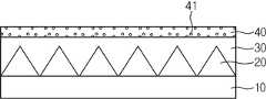
프리즘시트는 입체적 구조와 구조가 반복되어 형성된 구조화된 표면을 갖는 것으로, 일예로 삼각형 단면모양의 구조가 반복되어 골과 산(peak)를 형성한 경우(도 1 참조) 프리즘 산에서는 집광 효과를 극대화하여 정면 휘도를 상승시킬 수 있다. 그러나 구조의 측면부에서 방출되는 빛은 정면으로 집광되는 것이 아니고 일부 확산 또는 내부로 반사되어 충분히 휘도를 향상시키지 못하였다.The prism sheet has a structured surface in which a three-dimensional structure and structure are repeatedly formed. For example, in a case where a triangular cross-sectional structure is repeated to form a bone and a peak (see FIG. 1) So that the front luminance can be raised. However, the light emitted from the side surface of the structure is not focused on the front surface, but is partially diffused or reflected to the inside, so that the brightness can not be sufficiently improved.
또한 정면 휘도가 상승되는 만큼 상대적으로 반치각이 좁아지며 특정 시야각에서의 휘도가 급격하게 저하되는 컷-오프(cut-off) 현상이 발생하는 등의 시야각 특성 저하가 발생하는 문제점이 있다. 또한 패턴으로 인하여 휘선이 보이게 되며 이를 은폐하고 시야각을 보상하기 위해서 보호필름을 추가적으로 사용해야만 했다.Also, as the front luminance increases, the half-value angle becomes relatively narrow, and a cut-off phenomenon occurs in which the luminance at a specific viewing angle is rapidly lowered. Also, due to the pattern, a bright line was visible. In order to conceal it and to compensate for the viewing angle, additional protective film had to be used.
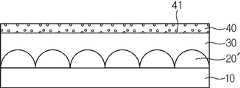
이러한 점을 고려하여 구조화된 표면의 형상을 도 2에 나타낸 것과 같이 그 단면이 반구인 기둥형상으로 변형한 경우도 있으나 이 경우에서도 휘도, 은폐성 및 시야각의 고른 향상을 기대할 수는 없었다.In view of this point, there is a case where the shape of the structured surface is transformed into a columnar shape whose cross section is hemispherical as shown in Fig. 2, but even in this case, the luminance, concealability and viewing angle can not be uniformly improved.
또한 통상의 프리즘 시트의 경우 프리즘 시트를 2장 겹쳐 사용할 수도 있으며 그 위에 다른 시트가 적층되는데 이 경우에는 시트 간 접촉면으로 인해 불량이 발생되는 문제점이 있었다.In addition, in the case of a normal prism sheet, two prism sheets can be used in a superimposed manner, and another sheet is stacked thereon. In this case, there is a problem that a defect occurs due to the contact surface between the sheets.
또한 이와 같은 광학구조면을 포함한 광학시트는 광학구조의 배열이 규칙적이기 때문에 액정 픽셀의 일정한 배열과 결합될 때 간섭효과로 물결무늬가 생기는 무아레(Moire) 현상과 같은 광간섭 이미지가 발생될 수 있는 여지를 남겨놓고 있다. 이는 규칙성이 중첩되는 구조에서는 피할 수 없는 물리적 현상이다.In addition, optical sheets including such an optical structural surface may have optical interference images such as a Moire phenomenon in which a wave pattern is generated due to an interference effect when combined with a certain arrangement of liquid crystal pixels because the arrangement of optical structures is regular It leaves room. This is an unavoidable physical phenomenon in a structure in which regularity overlaps.
본 발명은 구조화된 표면에서의 빛의 경로를 바꾸어 주어 정면 휘도를 보다향상시킨 광학시트를 제공하는 데 그 목적이 있다.An object of the present invention is to provide an optical sheet in which the light path on the structured surface is changed to improve the front luminance.
또한 본 발명은 은폐성과 시야각이 개선된 광학시트를 제공하는 데 그 목적이 있다.Another object of the present invention is to provide an optical sheet having improved hiding and viewing angles.
또한 본 발명은 다른 광학시트와의 적층시 접촉으로 인한 스크래치 불량을 감소시킬 수 있는 광학시트를 제공하는 데 그 목적이 있다.Another object of the present invention is to provide an optical sheet capable of reducing scratch defects due to contact with other optical sheets during lamination.
본 발명의 한 구현예에서는 한쪽 면에 구조화된 표면을 가지며 투명한 중합체 조성으로 이루어진 패턴층과; 패턴층에 인접하는 기재층을 포함하는 광학시트에 있어서, 패턴층의 구조화된 표면 전체를 덮도록 일정 두께로 형성되어 평탄화되어 있으며 패턴층과 대비하여 0.05 내지 20% 높은 굴절율을 갖는 고굴절층; 및 고굴절층의 평탄화면에 인접하여 형성되는 입자 코팅층을 포함하는 광학시트를 제공한다.In one embodiment of the present invention, a pattern layer having a structured surface on one side and a transparent polymer composition; An optical sheet comprising a substrate layer adjacent to a pattern layer, the optical sheet comprising: a high refractive index layer having a constant thickness and flattened to cover the entire structured surface of the pattern layer and having a refractive index of 0.05 to 20% higher than that of the pattern layer; And a particle coating layer formed adjacent to the flat screen of the high-refraction layer.
본 발명의 한 구현예에 따른 광학시트에 있어서, 고굴절층의 최대 두께는 기재층으로부터 구조화된 표면까지의 최고 높이에서 최저 높이를 뺀 것과 같거나 그보다 더 큰 값을 갖는 것일 수 있다.In an optical sheet according to one embodiment of the present invention, the maximum thickness of the high-refraction layer may be equal to or greater than the maximum height from the substrate layer to the structured surface minus the minimum height.
본 발명의 한 구현예에 따른 광학시트에 있어서, 입자코팅층은 투명한 바인더에 입자가 함유된 조액으로부터 형성된 것일 수 있다.In the optical sheet according to one embodiment of the present invention, the particle coating layer may be formed from a liquid containing particles in a transparent binder.
본 발명의 한 구현예에 따른 광학시트에 있어서, 입자는 직경이 0.01 내지 40㎛일 수 있다.In the optical sheet according to one embodiment of the present invention, the particles may have a diameter of 0.01 to 40 탆.
본 발명의 한 구현예에 따른 광학시트에 있어서, 패턴층은 다수의 기하학적 구조가 서로 인접하거나 이격적으로 형성된 구조화된 표면을 갖는 것일 수 있다.In the optical sheet according to one embodiment of the present invention, the pattern layer may have a structured surface in which a plurality of geometric structures are formed adjacent to each other or spaced apart from each other.
본 발명의 일 구현예에 의하면 구조화된 표면을 갖는 광학시트의 구조화된 표면 상에 구조화된 표면 전체를 덮도록 일정 두께로 패턴층에 비하여 굴절율이 0.05 내지 20% 높은 고굴절층이 형성됨으로써 다수의 구조들이 인접되거나 인접하 지 않고 형성된 패턴층을 거친 빛이 고굴절층을 통해 정면으로 집광되어 결과적으로 휘도를 향상시킬 수 있으며, 고굴절층 상에 입자코팅층을 둠으로써 시트간 밀착을 방지할 수 있어서 무아레 현상 등을 방지할 수 있고 또한 입자로 인한 확산 효과에 의해 은폐성 및 시야각이 개선된 광학시트를 제공할 수 있다.According to an embodiment of the present invention, a high refractive index layer having a refractive index of 0.05 to 20% higher than the pattern layer is formed to cover the entire structured surface on the structured surface of the optical sheet having a structured surface, The light passing through the pattern layer formed adjacently or not adjacent to each other can be converged to the front side through the high refractive index layer and consequently the brightness can be improved and the adhesion between the sheets can be prevented by providing the particle coating layer on the high refractive index layer, Can be prevented, and an optical sheet having improved concealability and a viewing angle due to the diffusion effect due to particles can be provided.
이하, 첨부된 도면을 참조하여 본 발명을 보다 상세히 설명한다.Hereinafter, the present invention will be described in more detail with reference to the accompanying drawings.
통상 광학 구조면을 포함하는 광학시트는 기재층과 패턴층을 포함하는 것으로, 패턴층은 기재층에의 인접하지 않은 나머지의 일면은 구조화된 표면을 갖는 형상을 가지며 투명한 중합체 조성으로 이루어진다. 특히 구조화된 표면은 입체적 구조와 구조가 서로 인접하거나 인접하지 않고 반복적으로 형성됨으로써 골과 산(peak)이 반복되는 구조를 갖는 것이 일반적이다.The optical sheet, which usually includes an optical structure surface, includes a base layer and a pattern layer, the other side of which is not adjacent to the base layer, has a shape with a structured surface and is made of a transparent polymer composition. In particular, the structured surface generally has a structure in which a bone and a peak are repeated by forming a three-dimensional structure and a structure repeatedly, not adjacent to each other, or adjacent to each other.
본 발명에 따른 광학시트의 일 실시예를 도 3 내지 도 4에 도시하였는바, 기재층(10)과, 기재층 상의 패턴층(20) 및 패턴층 상에 형성되며 평탄화된 고굴절층(30) 및 고굴절층(30) 상에 형성되는 입자코팅층(40)을 포함한다.3 to 4, an optical sheet according to an embodiment of the present invention includes a
도 3에 도시한 것은 패턴층(20)의 형상이 그 단면이 삼각형인 일반적인 프리즘 구조이며, 도 4에 도시한 것은 그 단면이 반원형인 기둥형상의 구조가 선형배열된 경우를 도시한 것이다. 도 3 또는 도 4에는 패턴층(20 또는 20')을 이루는 개개의 구조가 인접하여 형성된 경우만을 도시하였으나 이들이 이격적으로 떨어진 경우도 본 발명의 기술적 사상의 범위 내에 있다 할 것이다.3 shows a general prism structure in which the shape of the
그런데 좋기로는 광원으로부터 입사된 빛이 기재층(10)을 거쳐 먼저 저굴절율을 갖는 패턴층(20)을 거친 후 이로부터 출사된 빛이 고굴절층(30)을 거친 다음 최종적으로 출사되도록 하는 것이,BLU의 도광판 및 광확산 필름에서 출사되는 빛의 광경로 면에서 고굴절층(30)을 거친 최종 출사광이 정면 방향으로 집광될 수 있다는 점에서 더 유리할 수 있어서, 패턴층(20 또는 20')을 이루는 구조들은 서로 인접하여 형성된 것이 더 유리할 수 있다.It is preferable that the light incident from the light source passes through the
통상 패턴층(20)을 구성하는 투명한 중합체 조성은 특별하게 한정되는 것은 아니며, 종래 프리즘 시트 또는 프리즘 필름에 사용되는 공지의 수지들을 사용할 수 있다. 예컨대, 자외선 중합용 모노머 또는 올리고머의 혼합물 및 광개시제를 포함하는 조성일 수 있다.The transparent polymer composition constituting the
고굴절층(30)은 패턴층(20)을 구성하는 투명한 중합체 조성과 동일한 수지 조성을 가질 수 있으며, 다만 중합체 조성 중 굴절율을 향상시킬 수 있는 수지 성분을 더 추가하는 방법 등을 통해 굴절율을 상승시킨 것일 수 있다.The high
고굴절층(30)은 패턴층(20 또는 20')에 비하여 굴절율이 0.05 내지 20% 정도 더 큰 것이 바람직한데, 만일 고굴절층(30)의 굴절율이 패턴층에 비하여 같거나 0.05% 미만 정도로 더 클 경우에는 고굴절층(30)에서 출사되는 광의 경로가 정면에서 벗어나 중앙 휘도가 줄어들 수 있고, 굴절율이 20% 를 초과하여 지나치게 클 경우에는 고굴절층에서 전반사되는 빛이 증가하여 역시 중앙 휘도가 줄어들 수 있는 문제가 있을 수 있다.It is preferable that the refractive index of the high
고굴절층(30)은 광학구조면을 따라 형성되면서 평탄화되도록 소정 두께로 형성되는데, 고굴절층(30)의 최고 두께(TH)가 패턴층을 이루는 구조의 최고 높이에서 최저 높이를 뺀 높이(PH) 보다 작은 값을 갖는 경우에는 외관 품위가 떨어지며 휘도가 감소할 수 있고 또 지나치게 고굴절층(30)의 최고 두께(TH)가 커지는 경우에는 고굴절층에서 빛의 흡수가 증가하여 휘도가 감소할 수 있다는 점에서 불리할 수 있다.The high
한편 본 발명의 광학시트는 고굴절층(30) 상에 입자코팅층(40)이 형성되는바, 입자의 크기는 직경이 0.01 내지 40㎛인 단분산 또는 다분산 입자분포를 갖는 층일 수 있다. 입자의 크기가 상기 범위 이내일 때 입자층으로 인한 광확산 효과 면에서 적절한 광확산 효과를 낼 수 있다는 면과 입자의 탈리 등으로 인한 시트 손상을 방지할 수 있다는 점에서 유리할 수 있다.In the optical sheet of the present invention, the
입자 코팅층은 투명한 바인더에 입자를 분산시킨 조액으로부터 얻어질 수 있는 것으로, 투명한 바인더는 고굴절층과의 접착성이 좋으며 입자들과 상용성이 좋은 수지, 즉, 입자가 수지에 골고루 분산되어 분리되거나 침전이 잘 생기지 않는 것을 사용할 수 있으며 그 한정이 있는 것은 아니다.The particle coating layer can be obtained from a solution in which particles are dispersed in a transparent binder. The transparent binder is a resin having good adhesiveness to the high refractive index layer and being compatible with the particles, that is, the particles are uniformly dispersed in the resin, It is possible to use something that is not good, and there is no limitation.
입자로는 유기입자 또는 무기입자를 사용할 수 있다. 유기입자의 일예로는 메틸메타크릴레이트, 아크릴산, 메타크릴산, 히드록시에틸메타크릴레이트, 히드록 시프로필메타크릴레이트, 아크릴아미드, 메티롤아크릴아미드, 글리시딜메타크릴레이트, 에틸아크릴레이트, 이소부틸아크릴레이트, 노말부틸아크릴레이트, 2-에틸헥실아크릴레이트 단독 중합체 또는 공중합체의 아크릴계 입자와 폴리에틸렌, 폴리스티렌, 폴리프로필렌 등의 올레핀계 입자와 아크릴과 올레핀계의 공중합체 입자 및 단일중합체의 입자를 형성한 후 그 층위에 다른 종류의 단량체로 덮어 씌워 만든 다층 다성분계 입자를 사용하며, 무기 입자로서는 산화규소, 산화알루미늄, 산화티타늄, 산화지르코늄 및 불화마그네슘 등을 들 수 있다. 상기 유기 및 무기 입자들은 단지 예시적인 것에 불과하며, 상기 나열된 유기 또는 무기 재질의 입자에 한정되지 않고 본 발명의 주된 목적을 달성할 수 있는 한 다른 공지된 재료로 얼마든지 대체할 수 있음은 당업자에게는 자명하며, 이러한 재질 변경의 경우도 역시 본 발명의 기술적 사상의 범주 내이다.As the particles, organic particles or inorganic particles can be used. Examples of the organic particles include, but are not limited to, methyl methacrylate, acrylic acid, methacrylic acid, hydroxyethyl methacrylate, hydroxypropyl methacrylate, acrylamide, methylol acrylamide, glycidyl methacrylate, , Isobutyl acrylate, n-butyl acrylate, 2-ethylhexyl acrylate homopolymer or copolymer, an olefin-based particle such as polyethylene, polystyrene and polypropylene, an acrylic-olefin-based copolymer particle and a homopolymer Multi-component multi-component particles formed by forming particles and then covering them with other kinds of monomers are used. Examples of the inorganic particles include silicon oxide, aluminum oxide, titanium oxide, zirconium oxide and magnesium fluoride. It is to be understood that the organic and inorganic particles are merely illustrative and are not limited to the organic or inorganic particles listed above and may be replaced with any other known materials so long as the main purpose of the present invention can be achieved. And the case of such a material change is also within the scope of the technical idea of the present invention.
입자 코팅층(40)의 두께는 입자 크기와 함량에 따라 광확산성을 고려하여 0.1 내지 100㎛ 정도일 수 있다.The thickness of the
또한 본 발명의 광학 구조면을 갖는 광학필름에 있어서 기재층은 그 두께가 25 내지 500㎛ 정도일 수 있고, 기재층은 종래 프리즘 시트 또는 프리즘 필름에 사용되는 투명한 수지로 된 시트이면 어느 것이나 사용할 수 있다. 일예로 폴리에틸렌테레프탈레이트 필름, 폴리카보네이트 필름, 폴리프로필렌 필름, 폴리에틸렌 필름, 폴리스틸렌 필름 또는 폴리에폭시 필름 등을 들 수 있다.In the optical film having the optical structure surface of the present invention, the base layer may have a thickness of about 25 to 500 탆, and the base layer may be any of a conventional prism sheet or a sheet made of a transparent resin used for a prism film . For example, a polyethylene terephthalate film, a polycarbonate film, a polypropylene film, a polyethylene film, a polystyrene film, or a polyepoxy film can be given.
본 발명에서 패턴층(20 또는 20') 상에 고굴절층(30)을 형성함으로 인해 광경로가 달라지게 되는바, 통상 도 1 내지 도 2로 도시한 것과 같은 종래의 광학구조면을 갖는 패턴층에서는 패턴층의 산 부분에서는 집광 효과가 극대화되고 이로써 정면 휘도가 향상된다.In the present invention, since the high-refractive-
그러나 패턴층을 이루는 개개의 구조들의 측면부분에서는 빛의 굴절이 일어나게 되고 어떤 경우 전반사되어 광손실량이 증대될 수 있다.However, in the side portions of the individual structures constituting the pattern layer, light refraction occurs, and in some cases, total light loss may be increased.
그러나 패턴층(20)을 덮도록 고굴절층(30)이 형성되면 패턴층에서 굴절된 빛이 고굴절층(30)을 거치면서 굴절의 패턴이 달라지고 이는 다시 패턴층, 즉 저굴절층을 만나면서 집광된다. 따라서 정면 휘도가 상승되는 효과를 얻을 수 있다.However, when the high
그리고 고굴절층(30)로부터 집광된 빛은 입자코팅층(40)으로 입사되면서 입자로 인해 재확산됨으로써 무아레 현상을 없앨 수 있다.The light condensed from the high-
또한 입자 코팅층(40) 및 고굴절층(30)은 패턴층(20)의 광학구조면을 보호하는 기능을 할 수 있다.The
통상 광학구조면을 갖는 광학시트는 두 장 이상 적층하여 사용할 수 있으며 광학시트 상에 또 다른 광학시트가 적층될 수도 있는데, 패턴층(20)이 노출된 광학시트의 경우 시트간 접촉면에서 스크래치에 의해 광학구조가 손상될 수 있다.Usually, two or more optical sheets having an optical structure surface can be laminated and another optical sheet can be laminated on the optical sheet. In the case of the optical sheet in which the
그러나 패턴층(20) 상에 고굴절층(30) 및 입자코팅층(40)이 더 형성됨에 따라서 이러한 스크래치에 의한 손상을 방지할 수 있으며, 특히 입자코팅층(40)의 입자로 인해 시트간 밀착을 방지함으로써 이러한 효과가 더욱이 부각될 수 있다.However, since the high
다른 한편으로 입자코팅층(40)에 포함된 입자(41)에서는 약간의 확산이 일어 나게 되며, 이는 은폐성을 부여하여 휘선 보임을 가려주는 역할을 할 수 있다. 또한 시야각도 개선될 수 있도록 한다.On the other hand, a slight diffusion occurs in the
이상 도면을 참조하여 설명하였지만, 이로써 본 발명이 한정되는 것은 아니며, 본 발명이 속하는 기술분야에서 통상의 지식을 가진 당업자는 본 발명의 기술적 사상에서 벗어나지 않는 범위 내에서 변경하여 실시할 수 있음은 자명하다.It will be apparent to those skilled in the art that various modifications and variations can be made in the present invention without departing from the spirit or scope of the invention. Do.
이하, 본 발명의 실시예로 더욱 상세히 설명하나, 본 발명의 범위가 이들 실시예로 한정되는 것은 아니다.Hereinafter, the present invention will be described in more detail with reference to Examples, but the scope of the present invention is not limited to these Examples.
<비교예 1>≪ Comparative Example 1 &
폴리에틸렌테레프탈레이트 필름을 기재층(두께 188㎛)으로 하고, 여기에 아크릴레이트 올리고머(고굴절 아크릴레이트, 2-페닐에틸메타크릴레이트 및 1,6-헥사다이올아크릴레이트로 구성) 90중량%, 광개시제 5중량% 및 힌더드 페놀계 광안정제 5중량%로 이루어진 프리즘 조액으로부터 그 단면의 모양이 직각이등변삼각형 입체 패턴이 인접한 형태의 구조화된 표면을 갖도록 패턴층을 형성시킨 광학시트를 제작하였다(도 1 참조). 패턴층의 굴절율은 1.50이 되도록 하였다.A polyethylene terephthalate film was used as a base layer (thickness 188 탆), and 90% by weight of an acrylate oligomer (composed of high-refractive index acrylate, 2-phenylethyl methacrylate and 1,6-hexadiol acrylate) 5% by weight and a hindered phenolic light stabilizer in an amount of 5% by weight to form a patterned layer in such a manner that the cross-sectional shape of the isotropic triangular three-dimensional pattern had a structured surface of an adjacent shape Reference). The refractive index of the pattern layer was set to 1.50.
<비교예 2>≪ Comparative Example 2 &
폴리에틸렌테레프탈레이트 필름을 기재층으로 하고, 여기에 아크릴레이트 올리고머(고굴절 아크릴레이트, 2-페닐에틸메타크릴레이트 및 1,6-헥사다이올아크릴레이트로 구성) 90중량%, 광개시제 5중량% 및 힌더드 페놀계 광안정제 5중량%로 이 루어진 프리즘 조액으로부터 그 단면의 모양이 반원인 입체 패턴이 인접한 형태의 구조화된 표면을 갖도록 패턴층을 형성시킨 광학시트를 제작하였다(도 2 참조). 패턴층의 굴절율은 1.50이 되도록 하였다.A polyethylene terephthalate film was used as a substrate layer, and 90 wt% of an acrylate oligomer (consisting of high refractive index acrylate, 2-phenylethyl methacrylate and 1,6-hexadiol acrylate), 5 wt% of a photoinitiator, An optical sheet having a patterned layer formed so as to have a structured surface of a semicircular pattern having a semi-circular shape in cross-section was formed from a prism liquid solution containing 5 wt% of dodephenol light stabilizer (see Fig. 2). The refractive index of the pattern layer was set to 1.50.
<실시예 1>≪ Example 1 >
폴리에틸렌테레프탈레이트 필름을 기재층으로 하고, 여기에 아크릴레이트 올리고머(고굴절 아크릴레이트, 2-페닐에틸메타크릴레이트 및 1,6-헥사다이올아크릴레이트로 구성) 90중량%, 광개시제 5중량% 및 힌더드 페놀계 광안정제 5중량%로 이루어진 프리즘 조액으로부터 그 단면의 모양이 직각이등변삼각형 입체 패턴이 인접한 형태의 구조화된 표면을 갖도록 패턴층을 형성시켰다. 패턴층의 굴절율은 1.50이 되도록 하였다.A polyethylene terephthalate film was used as a substrate layer, and 90 wt% of an acrylate oligomer (consisting of high refractive index acrylate, 2-phenylethyl methacrylate and 1,6-hexadiol acrylate), 5 wt% of a photoinitiator, A pattern layer was formed so as to have a shape of a cross section and having a right-angled isosceles triangular three-dimensional pattern in the form of an adjacent structure from a prism tank liquid containing 5% by weight of dodephenol light stabilizer. The refractive index of the pattern layer was set to 1.50.
그 다음 프리즘층의 상부에 프리즘의 산 높이와 같은 두께로 균일하게, 아크릴레이트 올리고머(고굴절 아크릴레이트, 2-페닐에틸메타크릴레이트 및 1,6-헥사다이올아크릴레이트로 구성) 90중량%, 광개시제 5중량% 및 힌더드 페놀계 광안정제 5중량%로 이루어진 조액을 도포하여 고굴절층을 형성하되, 패턴층보다 굴절율이 0.02만큼 높도록 형성하였다.Next, 90% by weight of an acrylate oligomer (composed of high-refractive index acrylate, 2-phenylethyl methacrylate and 1,6-hexadiol acrylate) was uniformly dispersed in the upper portion of the prism layer to a thickness equal to the peak height of the prism, 5% by weight of a photoinitiator and 5% by weight of a hindered phenolic light stabilizer was applied to form a high-refraction layer having a refractive index higher than that of the pattern layer by 0.02.
그 다음 고굴절층 상에, 아크릴 수지 52-666(애경화학社) 100중량부에 메틸에틸케톤 70 중량부, 톨루엔 50중량부를 계량하고 희석하여 굴절율 1.50인 바인더 수지를 제조한 후, 평균입경 20um의 굴절율 1.50인 구형 폴리메틸메타크릴레이트 입자 MH20F(코오롱社)를 상기 바인더 수지 대비 110 중량부 되도록 혼합하여 그라 비아 코터를 사용하여 코팅 후 120도에서 60초간 경화시켜 건조함으로써 입자 코팅층을 형성하여, 도 3으로 도시한 것과 같은 광학시트를 제작하였다. 이때 입자 코팅층의 두께는 30㎛이었다.Subsequently, 70 parts by weight of methyl ethyl ketone and 50 parts by weight of toluene were metered and diluted on 100 parts by weight of acrylic resin 52-666 (Aekyou Chemical Co., Ltd.) on the high refractive index layer to prepare a binder resin having a refractive index of 1.50. The spherical polymethylmethacrylate particles MH20F having a refractive index of 1.50 (manufactured by Kolon) were mixed so as to be 110 parts by weight with respect to the binder resin, followed by coating with a Gravia coater, followed by curing at 120 ° C. for 60 seconds and drying to form a particle coating layer An optical sheet as shown in Fig. 3 was prepared. At this time, the thickness of the particle coating layer was 30 mu m.
<실시예 2>≪ Example 2 >
상기 실시예 1과 동일한 방법으로 광학시트를 제작하되, 다만 고굴절층 도포시 프리즘의 산 높이보다 5% 정도 더 두껍게 고굴절층이 형성되도록 하였다.An optical sheet was prepared in the same manner as in Example 1 except that a high refractive index layer was formed by 5% thicker than the peak height of the prism upon application of the high refractive index layer.
<실시예 3 내지 5>≪ Examples 3 to 5 &
상기 실시예 1과 동일한 방법으로 광학시트를 제작하되, 다만 고굴절층 조액을 조정하여 다음 표 1에 나타낸 것과 같은 패턴층과의 굴절율 차이를 갖도록 하였다.An optical sheet was prepared in the same manner as in Example 1 except that the refractive index difference with the pattern layer as shown in Table 1 below was adjusted by adjusting the solution of the high refractive index layer.
<실시예 6 내지 8>≪ Examples 6 to 8 >
상기 실시예 1과 동일한 방법으로 광학시트를 제작하되, 다만 입자코팅층에 있어서 입자의 종류를 다음 표 1과 같이 달리하였다.Optical sheets were prepared in the same manner as in Example 1 except that the types of particles in the particle coating layer were changed as shown in Table 1 below.
<실시예 9>≪ Example 9 >
폴리에틸렌테레프탈레이트 필름을 기재층으로 하고, 여기에 아크릴레이트 올리고머(고굴절 아크릴레이트, 2-페닐에틸메타크릴레이트 및 1,6-헥사다이올아크릴레이트로 구성) 90중량%, 광개시제 5중량% 및 힌더드 페놀계 광안정제 5중량%로 이 루어진 프리즘 조액으로부터 그 단면의 모양이 반원 기둥 형상이 인접한 형태의 구조화된 표면을 갖도록 패턴층을 형성시켰다. 패턴층의 굴절율은 1.50 되도록 하였다.A polyethylene terephthalate film was used as a substrate layer, and 90 wt% of an acrylate oligomer (consisting of high refractive index acrylate, 2-phenylethyl methacrylate and 1,6-hexadiol acrylate), 5 wt% of a photoinitiator, A pattern layer was formed so as to have a structured surface of a semi-circular columnar shape in cross-section from the prism bath solution containing 5 wt% of dodephenol light stabilizer. The refractive index of the pattern layer was 1.50.
그 다음 프리즘층의 상부에 반원 기둥의 정점의 높이와 같은 두께로 균일하게, 아크릴레이트 올리고머(고굴절 아크릴레이트, 2-페닐에틸메타크릴레이트 및 1,6-헥사다이올아크릴레이트로 구성) 90중량%, 광개시제 5중량% 및 힌더드 페놀계 광안정제 5중량%로 이루어진 조액을 도포하여 고굴절층을 형성하되, 패턴층에 비하여 굴절율이 0.02만큼 높도록 하였다.Then, 90 parts by weight of an acrylate oligomer (composed of high-refractive index acrylate, 2-phenylethyl methacrylate and 1,6-hexadiol acrylate) was uniformly added to the upper portion of the prism layer at a thickness equal to the height of the apex of the semi- %, A photoinitiator of 5 wt%, and a hindered phenolic light stabilizer of 5 wt% was applied to form a high-refraction layer having a refractive index as high as 0.02 as compared with the pattern layer.
그 다음 고굴절층 상에, 실시예1과 같은 조성으로 이루어진 조액을 도포하여 입자코팅층을 형성함으로써 도 3으로 도시한 것과 같은 광학시트를 제작하였다. 입자코팅층의 두께는 10 내지 30㎛이었다.Then, a coating liquid having the same composition as in Example 1 was coated on the high refractive index layer to form a particle coating layer, whereby an optical sheet as shown in Fig. 3 was produced. The thickness of the particle coating layer was 10 to 30 占 퐉.
<실시예 10>≪ Example 10 >
상기 실시예 9와 동일한 방법으로 광학시트를 제작하되, 다만 고굴절층 도포시 반원 기둥의 정점보다 5% 정도 더 두껍게 고굴절층이 형성되도록 하였다.An optical sheet was prepared in the same manner as in Example 9 except that a high refractive index layer was formed by 5% thicker than the peak of the semicircular column when the high refractive index layer was applied.
<실시예 11 내지 13>≪ Examples 11 to 13 >
상기 실시예 8과 동일한 방법으로 광학시트를 제작하되, 다만 고굴절층 조액을 조정하여 다음 표 1에 나타낸 것과 같은 패턴층과의 굴절율 차이를 갖도록 하였다.An optical sheet was prepared in the same manner as in Example 8 except that the refractive index difference between the high refractive index layer liquid and the pattern layer as shown in Table 1 below was adjusted.
패턴층 굴절율High refractive index layer refractive index -
Pattern layer refractive index
입자크기/두께Particle coating layer
Particle Size / Thickness
동일Semicircular pillar vertices and
same
5% 더 두꺼움Above the semicircular top
5% thicker
동일Semicircular pillar vertices and
same
동일Semicircular pillar vertices and
same
동일Semicircular pillar vertices and
same
상기 표 1에 있어서 고굴절층과 패턴층의 굴절율은, 각 층을 형성하기 위한 조액을 유리 판 위에 도포하고 UV 경화한 다음 박리하여 필름 상태의 것으로 측정한 값이며, 측정에는 굴절계(ATAGO ABBE사 제품, 모델명 1210 1T)를 이용하였다.The refraction indexes of the high refractive index layer and the pattern layer in Table 1 are values measured by coating the coating solution for forming each layer on a glass plate and UV-curing the film after peeling and measuring the refractive index of the film. The refractive index was measured using a refractometer (manufactured by ATAGO ABBE , Model name 1210 1T).
상기 비교예 1 내지 2 및 실시예 1 내지 13에 따라 얻어진 광학시트에 대하여 휘도, 은폐성, 시야각 및 광간섭현상을 평가하여 그 결과를 다음 표 2에 나타내었다.The optical sheets obtained in Comparative Examples 1 to 2 and Examples 1 to 13 were evaluated for brightness, hiding power, viewing angle and optical interference phenomenon, and the results are shown in Table 2 below.
구체 평가방법은 다음과 같다.The concrete evaluation method is as follows.
(1) 휘도(1) Brightness
휘도는 탑콘사의 BM-7을 이용하여 측정하였고, 값은 백라이트 유닛(BLU, 26인치)내 반사시트를 제외한 모든 시트류들을 제거하고 단순히 <광확산필름 1장+실시예 및 비교예의 광학필름 각 1장>의 조합을 사용하여 비교예 1의 광학필름과의 조합에 대한 휘도를 100으로 보고, 이에 대한 비교분으로 상기 실시예 및 비교예에 의하여 제조된 광학필름의 휘도 값을 측정하였다.The brightness was measured using BM-7 of Topcon Co. The values were obtained by removing all sheets except for the reflective sheet in the backlight unit (BLU, 26 inches) and simply using one sheet of light-diffusing film + The brightness of the optical film prepared in Examples and Comparative Examples was measured as a comparative value with respect to the brightness for the combination with the optical film of Comparative Example 1, using a combination of each one.
(2) 시야각(2) Viewing angle
시야각은 탑콘사의 BM-7을 이용하여 측정하였고, 값은 백라이트 유닛(BLU, 24인치)내 반사시트와 확산판를 제외한 모든 시트류들을 제거하고 실시예의 경우는 「광확산필름 1장/실시예의 프리즘시트 1장」 조합으로, 비교예의 경우는 「광확산필름 1장/(비교예 1 또는 비교예 2) 1장/보호필름 1장」의 조합을 사용하여, 각각의 광학시트 조합에 따른 정면(시야각=0˚위치) 휘도 대비 절반의 휘도값을 갖는 위치의 시야각을 측정하였다.The viewing angles were measured using a BM-7 from Topcon Co. The values were determined by removing all sheets except for the reflective sheet and the diffuser plate in the backlight unit (BLU, 24 inch), and in the case of the embodiment, Prism sheet 1 ", and in the case of the comparative example, a combination of " one light diffusion film / one (comparative example 1 or comparative example 2) / one protective film & (Viewing angle = 0 [deg.] Position). The viewing angle at a position having a luminance value half of the luminance was measured.
(3) 은폐성(3) Hiding property
은폐성은 탑콘사의 BM-7을 이용하여 측정하였고, 값은 백라이트 유닛(BLU, 24인치)내 반사시트와 확산판를 제외한 모든 시트류들을 제거하고 실시예의 경우는 「광확산필름 1장/실시예의 프리즘시트 1장」 조합으로, 비교예의 경우는 「광확산필름 1장/(비교예 1 또는 비교예 2) 1장/보호필름 1장」의 조합을 사용하여, 각각의 광학시트 조합에 따른 BLU의 수직 방향으로의 step point 측정 방식을 이용, 측정된 휘도값의 최대값 대비 휘도의 파동(fluctuation)값의 비로 광학필름의 은폐성을 측정하였으며 구체적으로는 다음 식과 같다.The hiding power was measured using a BM-7 of Topcon Co. The values were obtained by removing all sheets except for the reflective sheet and the diffuser plate in the backlight unit (BLU, 24 inch), and in the case of the embodiment, A combination of one sheet of light diffusion film / one sheet of Comparative Example 1 or Comparative Example 2 / one sheet of protective film "in the case of the comparative example, The hysteresis of the optical film was measured by the ratio of the fluctuation of the luminance to the maximum value of the measured luminance value using the step point measurement method in the vertical direction.
은폐성(%) = (휘도의 파동 폭)/(측정된 최대 휘도값)*100(%) = (Wave width of luminance) / (measured maximum luminance value) * 100
= (휘도의 파동 중 최고값 - 휘도의 파동 중 최소값)/(측정된 최대 휘도값)*100= (Maximum value of luminance waves - minimum value of luminance waves) / (maximum luminance value measured) * 100
(4) 광학간섭현상측정(4) Measurement of optical interference phenomenon
상기 각 실시예 및 비교예에 따른 광학시트 2장을 복수의 유리판 사이에 배치하고, 유리판에 압력을 가하여 필름에서 발생되는 과도한 밀착에 의한 광간섭현상(Wet-out, Newton's Ring)을 관찰하여, 각 현상의 발생 정도에 따라 하기와 같이 상대 평가하였다.Two optical sheets according to each of the examples and comparative examples were placed between a plurality of glass plates and a light interference phenomenon (wet-out, Newton's ring) caused by excessive adhesion generated in the film was observed by applying pressure to the glass plate, The relative evaluation was performed as follows according to the degree of occurrence of each phenomenon.
Wet-out : 발생 ← ◎ - ○ - △ - × → 미발생Wet-out: Occurrence ← ◎ - ○ - Δ - × → Not occur
Newton's Ring : 발생 ← ◎ - ○ - △ - × → 미발생Newton's Ring: Occurrence ← ◎ - ○ - Δ - × → Not occur
(°)Viewing angle
(°)
상기 물성평가 결과, 구조화된 표면 상에 고굴절층을 둔 경우(실시예 1 내지 13)은 비교예 1 내지 2에 비하여 휘도가 향상되었음을 알 수 있다. 실시예 2나 실시예 10과 같이 고굴절층의 최고 두께가 패턴의 정점보다 더 크게 형성되는 경우에는 동일한 높이로 형성된 것에 비하여 휘도가 상승함을 알 수 있다.As a result of the physical property evaluation, it can be seen that the brightness was improved in the case where the high refractive index layer was provided on the structured surface (Examples 1 to 13) as compared with Comparative Examples 1 and 2. As in Example 2 and Example 10, when the maximum thickness of the high-refraction layer is larger than the peak of the pattern, it can be seen that the brightness is higher than that of the high-refraction layer formed at the same height.
한편 입자코팅층을 갖는 본 발명에 따른 광학시트는 은폐성에 있어서도 비교예 1 또는 2에 비하여 향상된 결과를 보였고 또한 시야각도 보다 넓어지는 결과를 나타내었다.On the other hand, the optical sheet according to the present invention having a particle coating layer has improved hiding performance compared to Comparative Example 1 or 2, and also has a wider viewing angle.
은폐성 측면에서는, 실시예 6과 다른 실시예와 비교하였을 때 고굴절 상층의 입자 코팅층의 두께가 두꺼울 때가 입자층이 얇을 때 보다 은폐성이 높을 것을 알 수 있다.From the viewpoint of concealment, it can be seen that when the thickness of the particle coating layer of the high refractive index upper layer is thicker than that of Embodiment 6, the concealability is higher than when the particle layer is thin.
또한 본 발명에 따른 광학시트의 경우 시트간 과도한 밀착으로 인한 광간섭 현상이 적게 발생되었음을 볼 수 있다.Also, in the case of the optical sheet according to the present invention, it can be seen that the light interference phenomenon due to excessive adhesion between sheets occurs less.
도 1은 종래 구조화된 표면을 갖는 광학시트의 일 단면도.1 is a cross-sectional view of an optical sheet having a conventional structured surface;
도 2는 종래 구조화된 표면을 갖는 광학시트의 다른 단면도.2 is another cross-sectional view of an optical sheet having a conventional structured surface;
도 3은 본 발명 광학시트의 일 실시예에 따른 단면도.3 is a cross-sectional view according to one embodiment of the optical sheet of the present invention.
도 4는 본 발명 광학시트의 다른 실시예에 따른 단면도.4 is a sectional view according to another embodiment of the optical sheet of the present invention.
Claims (5)
Translated fromKoreanPriority Applications (1)
| Application Number | Priority Date | Filing Date | Title |
|---|---|---|---|
| KR1020080092634AKR101534341B1 (en) | 2008-09-22 | 2008-09-22 | An optical sheet including a high- |
Applications Claiming Priority (1)
| Application Number | Priority Date | Filing Date | Title |
|---|---|---|---|
| KR1020080092634AKR101534341B1 (en) | 2008-09-22 | 2008-09-22 | An optical sheet including a high- |
Publications (2)
| Publication Number | Publication Date |
|---|---|
| KR20100033664A KR20100033664A (en) | 2010-03-31 |
| KR101534341B1true KR101534341B1 (en) | 2015-07-06 |
Family
ID=42182465
Family Applications (1)
| Application Number | Title | Priority Date | Filing Date |
|---|---|---|---|
| KR1020080092634AExpired - Fee RelatedKR101534341B1 (en) | 2008-09-22 | 2008-09-22 | An optical sheet including a high- |
Country Status (1)
| Country | Link |
|---|---|
| KR (1) | KR101534341B1 (en) |
Families Citing this family (5)
| Publication number | Priority date | Publication date | Assignee | Title |
|---|---|---|---|---|
| KR102067162B1 (en)* | 2013-03-08 | 2020-01-16 | 삼성전자주식회사 | Film for improving color sense and method for preparing the same |
| KR102659654B1 (en)* | 2016-09-26 | 2024-04-23 | 삼성디스플레이 주식회사 | Display apparatus |
| US11327205B2 (en)* | 2019-07-29 | 2022-05-10 | Viavi Solutions Inc. | Encapsulated diffuser |
| KR102714565B1 (en)* | 2019-12-31 | 2024-10-07 | 엘지디스플레이 주식회사 | Privacy protecting film and liquid crystal display device comrpising the same |
| CN118584717B (en)* | 2024-06-25 | 2025-04-08 | 深圳市盛三友电子有限公司 | Polarizer and display device |
Citations (3)
| Publication number | Priority date | Publication date | Assignee | Title |
|---|---|---|---|---|
| KR20060057857A (en)* | 2004-11-24 | 2006-05-29 | 삼성전자주식회사 | Prism Sheet and Backlight Unit |
| JP2007256493A (en)* | 2006-03-22 | 2007-10-04 | Sony Corp | Optical sheet, method of manufacturing optical sheet, back light apparatus, and and liquid crystal display |
| JP2008176318A (en)* | 2006-12-29 | 2008-07-31 | Eternal Chemical Co Ltd | Scratch-resistant thin film |
- 2008
- 2008-09-22KRKR1020080092634Apatent/KR101534341B1/ennot_activeExpired - Fee Related
Patent Citations (3)
| Publication number | Priority date | Publication date | Assignee | Title |
|---|---|---|---|---|
| KR20060057857A (en)* | 2004-11-24 | 2006-05-29 | 삼성전자주식회사 | Prism Sheet and Backlight Unit |
| JP2007256493A (en)* | 2006-03-22 | 2007-10-04 | Sony Corp | Optical sheet, method of manufacturing optical sheet, back light apparatus, and and liquid crystal display |
| JP2008176318A (en)* | 2006-12-29 | 2008-07-31 | Eternal Chemical Co Ltd | Scratch-resistant thin film |
Also Published As
| Publication number | Publication date |
|---|---|
| KR20100033664A (en) | 2010-03-31 |
Similar Documents
| Publication | Publication Date | Title |
|---|---|---|
| JP5313898B2 (en) | Backlight suitable for display devices | |
| KR100980072B1 (en) | Optical Composite Film | |
| KR20100033663A (en) | Optical sheet | |
| WO2010041656A1 (en) | Optical sheet, surface light source device, and transmission display device | |
| JP2011501219A (en) | Higher transmittance light control film | |
| KR100844586B1 (en) | Luminance Enhancement Plate | |
| KR101534341B1 (en) | An optical sheet including a high- | |
| JP2010210882A (en) | Optical sheet and display using the same | |
| KR20110065610A (en) | Condensing optical sheet | |
| KR100920645B1 (en) | Prism Composite Film | |
| KR20080063543A (en) | Luminance enhancement plate and manufacturing method | |
| CN106154368A (en) | A kind of multi-functional complex optical film | |
| JP2009198749A (en) | Light beam control member | |
| KR20140003855A (en) | Lamination type optical sheet | |
| KR20070013677A (en) | Light control film | |
| KR100980068B1 (en) | Optical Composite Film | |
| KR100988764B1 (en) | Optical Composite Film | |
| KR101767137B1 (en) | Composition optical sheet including function of diffusion plate integrated light diffusion means | |
| JP4631366B2 (en) | Light control film laminate and projection screen using the same | |
| KR101203782B1 (en) | Prism sheet | |
| KR20080087437A (en) | Optical film with structured surface | |
| JP5011870B2 (en) | Rear projection screen | |
| KR20120078507A (en) | Condensing type optical sheet | |
| KR100544518B1 (en) | Prism film with minimal light loss | |
| KR20090051408A (en) | Condensing optical film |
Legal Events
| Date | Code | Title | Description |
|---|---|---|---|
| PA0109 | Patent application | St.27 status event code:A-0-1-A10-A12-nap-PA0109 | |
| R18-X000 | Changes to party contact information recorded | St.27 status event code:A-3-3-R10-R18-oth-X000 | |
| PN2301 | Change of applicant | St.27 status event code:A-3-3-R10-R13-asn-PN2301 St.27 status event code:A-3-3-R10-R11-asn-PN2301 | |
| PG1501 | Laying open of application | St.27 status event code:A-1-1-Q10-Q12-nap-PG1501 | |
| PN2301 | Change of applicant | St.27 status event code:A-3-3-R10-R11-asn-PN2301 | |
| R19-X000 | Request for party data change rejected | St.27 status event code:A-3-3-R10-R19-oth-X000 | |
| PN2301 | Change of applicant | St.27 status event code:A-3-3-R10-R11-asn-PN2301 | |
| R19-X000 | Request for party data change rejected | St.27 status event code:A-3-3-R10-R19-oth-X000 | |
| N231 | Notification of change of applicant | ||
| PN2301 | Change of applicant | St.27 status event code:A-3-3-R10-R13-asn-PN2301 St.27 status event code:A-3-3-R10-R11-asn-PN2301 | |
| R17-X000 | Change to representative recorded | St.27 status event code:A-3-3-R10-R17-oth-X000 | |
| PN2301 | Change of applicant | St.27 status event code:A-3-3-R10-R13-asn-PN2301 St.27 status event code:A-3-3-R10-R11-asn-PN2301 | |
| R17-X000 | Change to representative recorded | St.27 status event code:A-3-3-R10-R17-oth-X000 | |
| PN2301 | Change of applicant | St.27 status event code:A-3-3-R10-R13-asn-PN2301 St.27 status event code:A-3-3-R10-R11-asn-PN2301 | |
| A201 | Request for examination | ||
| PA0201 | Request for examination | St.27 status event code:A-1-2-D10-D11-exm-PA0201 | |
| R17-X000 | Change to representative recorded | St.27 status event code:A-3-3-R10-R17-oth-X000 | |
| E902 | Notification of reason for refusal | ||
| PE0902 | Notice of grounds for rejection | St.27 status event code:A-1-2-D10-D21-exm-PE0902 | |
| T11-X000 | Administrative time limit extension requested | St.27 status event code:U-3-3-T10-T11-oth-X000 | |
| R18-X000 | Changes to party contact information recorded | St.27 status event code:A-3-3-R10-R18-oth-X000 | |
| T11-X000 | Administrative time limit extension requested | St.27 status event code:U-3-3-T10-T11-oth-X000 | |
| E13-X000 | Pre-grant limitation requested | St.27 status event code:A-2-3-E10-E13-lim-X000 | |
| P11-X000 | Amendment of application requested | St.27 status event code:A-2-2-P10-P11-nap-X000 | |
| P13-X000 | Application amended | St.27 status event code:A-2-2-P10-P13-nap-X000 | |
| E902 | Notification of reason for refusal | ||
| PE0902 | Notice of grounds for rejection | St.27 status event code:A-1-2-D10-D21-exm-PE0902 | |
| T11-X000 | Administrative time limit extension requested | St.27 status event code:U-3-3-T10-T11-oth-X000 | |
| P11-X000 | Amendment of application requested | St.27 status event code:A-2-2-P10-P11-nap-X000 | |
| P13-X000 | Application amended | St.27 status event code:A-2-2-P10-P13-nap-X000 | |
| E701 | Decision to grant or registration of patent right | ||
| PE0701 | Decision of registration | St.27 status event code:A-1-2-D10-D22-exm-PE0701 | |
| PR0701 | Registration of establishment | St.27 status event code:A-2-4-F10-F11-exm-PR0701 | |
| PR1002 | Payment of registration fee | St.27 status event code:A-2-2-U10-U11-oth-PR1002 Fee payment year number:1 | |
| PG1601 | Publication of registration | St.27 status event code:A-4-4-Q10-Q13-nap-PG1601 | |
| P22-X000 | Classification modified | St.27 status event code:A-4-4-P10-P22-nap-X000 | |
| R18-X000 | Changes to party contact information recorded | St.27 status event code:A-5-5-R10-R18-oth-X000 | |
| PN2301 | Change of applicant | St.27 status event code:A-5-5-R10-R13-asn-PN2301 St.27 status event code:A-5-5-R10-R11-asn-PN2301 | |
| R18-X000 | Changes to party contact information recorded | St.27 status event code:A-5-5-R10-R18-oth-X000 | |
| LAPS | Lapse due to unpaid annual fee | ||
| PC1903 | Unpaid annual fee | St.27 status event code:A-4-4-U10-U13-oth-PC1903 Not in force date:20180701 Payment event data comment text:Termination Category : DEFAULT_OF_REGISTRATION_FEE | |
| PN2301 | Change of applicant | St.27 status event code:A-5-5-R10-R13-asn-PN2301 St.27 status event code:A-5-5-R10-R11-asn-PN2301 | |
| PC1903 | Unpaid annual fee | St.27 status event code:N-4-6-H10-H13-oth-PC1903 Ip right cessation event data comment text:Termination Category : DEFAULT_OF_REGISTRATION_FEE Not in force date:20180701 | |
| R18-X000 | Changes to party contact information recorded | St.27 status event code:A-5-5-R10-R18-oth-X000 |