KR101534097B1 - Apparatus for obtaining medical image and method for adjusting location of table by using the same - Google Patents
Apparatus for obtaining medical image and method for adjusting location of table by using the sameDownload PDFInfo
- Publication number
- KR101534097B1 KR101534097B1KR1020130096129AKR20130096129AKR101534097B1KR 101534097 B1KR101534097 B1KR 101534097B1KR 1020130096129 AKR1020130096129 AKR 1020130096129AKR 20130096129 AKR20130096129 AKR 20130096129AKR 101534097 B1KR101534097 B1KR 101534097B1
- Authority
- KR
- South Korea
- Prior art keywords
- indicator
- axis
- point
- unit
- distance
- Prior art date
- Legal status (The legal status is an assumption and is not a legal conclusion. Google has not performed a legal analysis and makes no representation as to the accuracy of the status listed.)
- Expired - Fee Related
Links
Images


Classifications
- A—HUMAN NECESSITIES
- A61—MEDICAL OR VETERINARY SCIENCE; HYGIENE
- A61B—DIAGNOSIS; SURGERY; IDENTIFICATION
- A61B5/00—Measuring for diagnostic purposes; Identification of persons
- A61B5/70—Means for positioning the patient in relation to the detecting, measuring or recording means
- A61B5/706—Indicia not located on the patient, e.g. floor marking
- A—HUMAN NECESSITIES
- A61—MEDICAL OR VETERINARY SCIENCE; HYGIENE
- A61B—DIAGNOSIS; SURGERY; IDENTIFICATION
- A61B5/00—Measuring for diagnostic purposes; Identification of persons
- A61B5/05—Detecting, measuring or recording for diagnosis by means of electric currents or magnetic fields; Measuring using microwaves or radio waves
- A61B5/055—Detecting, measuring or recording for diagnosis by means of electric currents or magnetic fields; Measuring using microwaves or radio waves involving electronic [EMR] or nuclear [NMR] magnetic resonance, e.g. magnetic resonance imaging
- A—HUMAN NECESSITIES
- A61—MEDICAL OR VETERINARY SCIENCE; HYGIENE
- A61B—DIAGNOSIS; SURGERY; IDENTIFICATION
- A61B6/00—Apparatus or devices for radiation diagnosis; Apparatus or devices for radiation diagnosis combined with radiation therapy equipment
- A61B6/04—Positioning of patients; Tiltable beds or the like
- A61B6/0407—Supports, e.g. tables or beds, for the body or parts of the body
- A—HUMAN NECESSITIES
- A61—MEDICAL OR VETERINARY SCIENCE; HYGIENE
- A61B—DIAGNOSIS; SURGERY; IDENTIFICATION
- A61B6/00—Apparatus or devices for radiation diagnosis; Apparatus or devices for radiation diagnosis combined with radiation therapy equipment
- A61B6/04—Positioning of patients; Tiltable beds or the like
- A61B6/0492—Positioning of patients; Tiltable beds or the like using markers or indicia for aiding patient positioning
- A—HUMAN NECESSITIES
- A61—MEDICAL OR VETERINARY SCIENCE; HYGIENE
- A61B—DIAGNOSIS; SURGERY; IDENTIFICATION
- A61B6/00—Apparatus or devices for radiation diagnosis; Apparatus or devices for radiation diagnosis combined with radiation therapy equipment
- A61B6/56—Details of data transmission or power supply, e.g. use of slip rings
- G—PHYSICS
- G06—COMPUTING OR CALCULATING; COUNTING
- G06K—GRAPHICAL DATA READING; PRESENTATION OF DATA; RECORD CARRIERS; HANDLING RECORD CARRIERS
- G06K7/00—Methods or arrangements for sensing record carriers, e.g. for reading patterns
- G06K7/10—Methods or arrangements for sensing record carriers, e.g. for reading patterns by electromagnetic radiation, e.g. optical sensing; by corpuscular radiation
- G06K7/10009—Methods or arrangements for sensing record carriers, e.g. for reading patterns by electromagnetic radiation, e.g. optical sensing; by corpuscular radiation sensing by radiation using wavelengths larger than 0.1 mm, e.g. radio-waves or microwaves
- G06K7/10198—Methods or arrangements for sensing record carriers, e.g. for reading patterns by electromagnetic radiation, e.g. optical sensing; by corpuscular radiation sensing by radiation using wavelengths larger than 0.1 mm, e.g. radio-waves or microwaves setting parameters for the interrogator, e.g. programming parameters and operating modes
- A—HUMAN NECESSITIES
- A61—MEDICAL OR VETERINARY SCIENCE; HYGIENE
- A61B—DIAGNOSIS; SURGERY; IDENTIFICATION
- A61B6/00—Apparatus or devices for radiation diagnosis; Apparatus or devices for radiation diagnosis combined with radiation therapy equipment
- A61B6/02—Arrangements for diagnosis sequentially in different planes; Stereoscopic radiation diagnosis
- A61B6/03—Computed tomography [CT]
- A—HUMAN NECESSITIES
- A61—MEDICAL OR VETERINARY SCIENCE; HYGIENE
- A61B—DIAGNOSIS; SURGERY; IDENTIFICATION
- A61B6/00—Apparatus or devices for radiation diagnosis; Apparatus or devices for radiation diagnosis combined with radiation therapy equipment
- A61B6/04—Positioning of patients; Tiltable beds or the like
- A61B6/0487—Motor-assisted positioning
Landscapes
- Health & Medical Sciences (AREA)
- Life Sciences & Earth Sciences (AREA)
- Engineering & Computer Science (AREA)
- Medical Informatics (AREA)
- Physics & Mathematics (AREA)
- General Health & Medical Sciences (AREA)
- Biophysics (AREA)
- Veterinary Medicine (AREA)
- Animal Behavior & Ethology (AREA)
- Public Health (AREA)
- Pathology (AREA)
- Biomedical Technology (AREA)
- Heart & Thoracic Surgery (AREA)
- Molecular Biology (AREA)
- Surgery (AREA)
- Nuclear Medicine, Radiotherapy & Molecular Imaging (AREA)
- Radiology & Medical Imaging (AREA)
- High Energy & Nuclear Physics (AREA)
- Optics & Photonics (AREA)
- Toxicology (AREA)
- Computer Networks & Wireless Communication (AREA)
- Electromagnetism (AREA)
- Artificial Intelligence (AREA)
- Computer Vision & Pattern Recognition (AREA)
- General Physics & Mathematics (AREA)
- Theoretical Computer Science (AREA)
- Apparatus For Radiation Diagnosis (AREA)
- Magnetic Resonance Imaging Apparatus (AREA)
Abstract
Translated fromKoreanDescription
Translated fromKorean본 발명은 의료 영상 장치 분야에 관한 것이다. 보다 구체적으로, 본 발명은 의료 영상 촬영 장치 및 이를 이용한 테이블의 위치 조절 방법에 관한 것이다.The present invention relates to the field of medical imaging devices. More particularly, the present invention relates to a medical image photographing apparatus and a method of adjusting a position of a table using the same.
의료 영상 촬영 장치는 대상체의 내부 구조를 이미지로 획득하기 위한 장비이다. 의료 영상 촬영 장치는 비침습 검사 장치로서, 신체 내의 구조적 세부사항, 내부 조직 및 유체의 흐름 등에 대해 보여준다. 의료 영상 촬영 장치는 MRI(Magnetic Resonance Imaging) 장치, CT(Computed Tomography) 장치, 초음파 장치, 엑스레이 장치 등을 포함한다.A medical image capturing apparatus is an apparatus for acquiring an internal structure of an object as an image. The medical imaging device is a non-invasive testing device that shows structural details, internal tissue and fluid flow in the body. The medical imaging apparatus includes an MRI (Magnetic Resonance Imaging) apparatus, a CT (Computed Tomography) apparatus, an ultrasonic apparatus, and an X-ray apparatus.
의료 영상 촬영 장치 중 MRI 장치는 일정 세기의 자기장에서 발생하는 RF(Radio Frequency) 신호에 대한 MR(Magnetic Resonance) 신호의 세기를 명암 대비로 표현하여 대상체의 단층 부위에 대한 이미지를 획득하는 기기이다. 예를 들어, 대상체를 강력한 자기장 속에 눕힌 후 특정의 원자핵(예컨대, 수소 원자핵 등)만을 공명시키는 RF 신호를 대상체에 순간적으로 조사했다가 중단하면 상기 특정의 원자핵에서 MR 신호가 방출되는데, MRI 장치는 이 MR 신호를 수신하여 MR 이미지를 획득할 수 있다. MRI 장치는 다른 이미징 장치들과는 다른 특징들을 포함한다. 이미지의 획득이 감지 하드웨어(detecting hardware)의 방향에 의존하는 CT와 같은 이미징 장치들과 달리, MRI 장치는 임의의 지점으로 지향된 2D 이미지 또는 3D 볼륨 이미지를 획득할 수 있다. 또한, MRI 장치는, CT, X-ray, PET 및 SPECT와 달리, 대상체 및 검사자에게 방사선을 노출시키지 않으며, 높은 연부 조직(soft tissue) 대조도를 갖는 이미지의 획득이 가능하여, 비정상적인 조직의 명확한 묘사가 중요한 신경(neurological) 이미지, 혈관 내부(intravascular) 이미지, 근 골격(musculoskeletal) 이미지 및 종양(oncologic) 이미지 등을 획득할 수 있다.Among the medical imaging apparatuses, an MRI apparatus is an apparatus that acquires an image of a single-layer region of a target object by expressing intensity of a magnetic resonance (MR) signal for an RF (Radio Frequency) signal generated in a magnetic field of a constant intensity in contrast. For example, when an object is instantly examined and discontinued after an RF signal that lies in a strong magnetic field and resonates only with a specific atomic nucleus (e.g., a hydrogen nucleus), the MR signal is emitted from the specific atomic nucleus. And the MR image can be acquired by receiving the MR signal. The MRI apparatus includes features different from other imaging apparatuses. Unlike imaging devices, such as CT, where acquisition of an image is dependent on the direction of the detecting hardware, the MRI device can acquire a 2D image or a 3D volume image directed to any point. Also, unlike CT, X-ray, PET, and SPECT, an MRI apparatus does not expose radiation to a subject and an examinee, and can acquire images having a high soft tissue contrast, The neurological image, the intravascular image, the musculoskeletal image and the oncologic image can be acquired.
의료 영상 촬영 장치 중 CT 장치는 대상체에 대한 적어도 하나의 축을 중심으로 회전하며 대상체를 촬영함으로써 대상체의 엑스레이 영상을 획득하는 장치이다. CT 장치는 대상체에 대한 단면 영상을 제공할 수 있으므로, 일반적인 엑스레이 장치에 비하여 대상체의 내부 구조(예컨대, 신장, 폐 등의 장기 등)가 겹치지 않게 표현할 수 있다는 장점이 있다.Among the medical image capturing apparatuses, the CT apparatus is an apparatus that acquires an x-ray image of a target object by rotating the object around at least one axis and photographing the object. The CT apparatus can provide a cross-sectional image of a target object, so that the internal structure of the target object (for example, an organ such as a kidney, lung, etc.) can be expressed without overlapping with a general X-ray apparatus.
MRI 장치와 CT 장치는 모두 의료 영상을 촬영하기 위해 대상체가 내부에 위치하게 되는 갠트리를 포함한다. 대상체는 테이블에 의해 지지되고, 테이블이 갠트리 내부로 이동하여 테이블 상의 대상체는 갠트리에 포함된 RF 코일, 엑스선 튜브 등에 의해 촬영된다.Both the MRI apparatus and the CT apparatus include a gantry in which an object is located inside to photograph a medical image. The object is supported by the table, the table moves into the gantry, and the object on the table is photographed by the RF coil, x-ray tube, etc. contained in the gantry.
대상체의 촬영 부위는 머리, 다리, 목, 복부 등 그 종류가 다양하기 때문에 대상체의 촬영 부위를 갠트리 내의 기준 지점, 예를 들어, 갠트리 내부의 중앙부 등에 위치시키는 것은 의료 영상의 퀄리티를 확보하는데 매우 중요한 사항이다.Since the photographing part of the object has various kinds such as head, leg, neck, abdomen, etc., positioning the photographing part of the object to a reference point in the gantry, for example, the center part of the inside of the gantry is very important for ensuring the quality of the medical image .
본 발명의 일 실시예에 따른 의료 영상 촬영 장치 및 이를 이용한 테이블의 위치 조절 방법은 사용자가 대상체의 촬영 지점을 쉽고 정확하게 설정할 수 있게 하는 것을 목적으로 한다.A medical image photographing apparatus and a method of adjusting a position of a table using the apparatus according to an embodiment of the present invention aim to enable a user to easily and accurately set a photographing point of a target object.
본 발명의 일 실시예에 따른 테이블의 위치 조절 방법은,According to another aspect of the present invention,
의료 영상 촬영 장치가 대상체를 지지하는 테이블의 위치를 조절하는 방법에 있어서, 제 1 축을 따라 배치된 복수의 감지부 각각과 사용자에 의해 임의의 지점에 위치된 인디케이터 사이의 거리들을 측정하는 단계; 상기 측정된 거리들과, 기준 지점에 대한 상기 복수의 감지부들 각각의 상대적인 위치를 이용하여 상기 기준 지점과 상기 인디케이터 사이의 제 1 축 상의 거리(이하, 제 1 축 거리)를 계산하는 단계; 및 상기 계산된 제 1 축 거리에 기초하여, 상기 테이블을 의료 영상 획득 장치의 갠트리 내부로 이동시키는 단계를 포함할 수 있다.A method of adjusting a position of a table supporting a target object by a medical imaging apparatus, comprising the steps of: measuring distances between each of a plurality of sensing units arranged along a first axis and an indicator positioned at an arbitrary point by a user; Calculating a distance on a first axis (hereinafter referred to as a first axis distance) between the reference point and the indicator using the measured distances and a relative position of each of the plurality of sensors with respect to the reference point; And moving the table into the gantry of the medical imaging device based on the calculated first axis distance.
상기 측정하는 단계는, 상기 제 1 축과 상이한 제 2 축을 따라 배치된 복수의 제 2 감지부 각각과 상기 인디케이터 사이의 거리들을 측정하는 단계를 포함하고, 상기 계산하는 단계는, 상기 복수의 제 2 감지부 각각과 상기 인디케이터 사이의 거리들, 및 상기 기준 지점에 대한 상기 복수의 감지부들 각각의 상대적인 위치를 이용하여, 상기 기준 지점과 상기 인디케이터 사이의 제 2 축 상의 거리(이하, 제 2 축 거리)를 계산하는 단계를 포함하고, 상기 테이블을 이동시키는 단계는, 상기 계산된 제 2 축 거리에 기초하여, 상기 테이블의 높이를 조절하는 단계를 포함할 수 있다.Wherein the measuring step comprises measuring distances between each of the plurality of second sensing portions disposed along a second axis different from the first axis and the indicator, A distance between the reference point and the indicator on the second axis (hereinafter referred to as a second axis distance (hereinafter referred to as " second axis distance ") between the reference point and the indicator by using the distances between each of the sensing units and the indicator, and the relative position of each of the plurality of sensing units with respect to the reference point, Wherein the step of moving the table may include adjusting a height of the table based on the calculated second axis distance.
상기 제 1 축과 상기 제 2 축은, 서로 수직일 수 있다.The first axis and the second axis may be perpendicular to each other.
상기 테이블의 위치 조절 방법은, 상기 기준 지점으로부터 상기 계산된 제 1 축 거리만큼 이격된 상기 대상체 상의 지점을 촬영 지점으로 설정하는 단계를 더 포함하고, 상기 이동시키는 단계는, 상기 촬영 지점이 상기 갠트리의 내부에 위치하도록 상기 테이블을 이동시키는 단계를 포함할 수 있다.Wherein the step of adjusting the position of the table further comprises setting a point on the object that is spaced apart from the reference point by the calculated first axis distance as a photographing point, And moving the table so that the table is located inside of the table.
상기 테이블의 위치 조절 방법은, 상기 인디케이터로부터 촬영 지점 설정 요청을 수신하는 단계를 더 포함할 수 있다.The method of adjusting the position of the table may further include receiving a photographing point setting request from the indicator.
상기 계산하는 단계는, 상기 제 1 축 거리의 계산이 완료된 후, 촬영 지점의 설정이 완료되었음을 나타내는 메시지를 상기 인디케이터로 전송하는 단계를 포함할 수 있다.The calculating may include transmitting a message to the indicator that the setting of the shooting point is completed after the calculation of the first axis distance is completed.
상기 테이블을 이동시키는 단계는, 상기 인디케이터로부터 테이블 이동 요청을 수신하는 단계를 포함할 수 있다.The step of moving the table may include receiving a table movement request from the indicator.
상기 인디케이터는, RFID 태그를 포함하고, 상기 복수의 감지부는, 복수의 RFID 리더기를 포함할 수 있다.The indicator may include an RFID tag, and the plurality of sensing units may include a plurality of RFID readers.
상기 측정하는 단계는, 상기 복수의 RFID 리더기 각각으로부터 제 1 신호가 방출된 때부터 상기 RFID 태그로부터 방출되는 제 2 신호가 상기 복수의 RFID 리더기 각각으로 수신될 때까지 걸리는 시간을 이용하여 상기 복수의 RFID 리더기 각각과 상기 RFID 태그 사이의 거리들을 측정하는 단계를 포함할 수 있다.Wherein the measuring step includes measuring a time period from when the first signal is emitted from each of the plurality of RFID readers to when the second signal emitted from the RFID tag is received by each of the plurality of RFID readers, And measuring distances between each of the RFID readers and the RFID tag.
상기 의료 영상 촬영 장치는, MRI 장치 또는 CT 장치를 포함할 수 있다.The medical image photographing apparatus may include an MRI apparatus or a CT apparatus.
본 발명의 다른 실시예에 따른 테이블의 위치 조절 방법은,According to another aspect of the present invention,
무선 인디케이터가 대상체를 지지하는 테이블의 위치를 조절하는 방법에 있어서, 사용자의 제 1 입력에 기초하여, 상기 무선 인디케이터에 부착된 RFID 태그를 활성화시키는 단계; 의료 영상 촬영 장치의 RFID 리더기를 통해 인식된 상기 무선 인디케이터의 위치를 기준으로 촬영 지점의 설정이 완료되었음을 나타내는 메시지를 상기 의료 영상 촬영 장치로부터 수신하는 단계; 및 상기 사용자의 제 2 입력에 기초하여, 테이블 이동 요청을 의료 영상 촬영 장치로 전송하는 단계를 포함할 수 있다.A method of adjusting a position of a table in which a wireless indicator supports an object, comprising: activating an RFID tag attached to the wireless indicator based on a first input of a user; Receiving a message from the medical image capturing apparatus indicating that the setting of the photographing point is completed based on the position of the wireless indicator recognized by the RFID reader of the medical image capturing apparatus; And transmitting a table movement request to the medical imaging device based on the second input of the user.
상기 테이블의 위치 조절 방법은, 상기 RFID 태그를 활성화시킨 이후, 소정 시간 내에 상기 의료 영상 촬영 장치로부터 상기 메시지를 수신하지 못한 경우, 상기 무선 인디케이터의 위치의 재조정을 요청하는 메시지를 출력하는 단계를 더 포함할 수 있다.The method further includes the step of outputting a message requesting repositioning of the wireless indicator when the message is not received from the medical imaging device within a predetermined time after activating the RFID tag .
상기 테이블의 위치 조절 방법을 실행하기 위한 컴퓨터 프로그램이 컴퓨터로 읽을 수 있는 기록 매체에 기록될 수 있다.A computer program for executing the position adjustment method of the table may be recorded on a computer-readable recording medium.
본 발명의 일 실시예에 따른 의료 영상 촬영 장치는,According to an embodiment of the present invention,
대상체를 지지하는 테이블의 위치를 조절하는 의료 영상 촬영 장치에 있어서, 제 1 축을 따라 배치된 복수의 감지부 각각과 사용자에 의해 임의의 지점에 위치된 인디케이터 사이의 거리들을 측정하는 거리 측정부; 상기 측정된 거리들과, 기준 지점에 대한 상기 복수의 감지부들 각각의 상대적인 위치를 이용하여 상기 기준 지점과 상기 인디케이터 사이의 제 1 축 상의 거리(이하, 제 1 축 거리)를 계산하는 촬영 지점 설정부; 및 상기 계산된 제 1 축 거리에 기초하여, 상기 테이블을 의료 영상 획득 장치의 갠트리 내부로 이동시키는 테이블 제어부를 포함할 수 있다.A medical image photographing apparatus for adjusting a position of a table supporting an object, comprising: a distance measuring unit for measuring distances between each of a plurality of sensing units arranged along a first axis and an indicator positioned at an arbitrary point by a user; (Hereinafter referred to as a first axis distance) between the reference point and the indicator by using the measured distances and the relative positions of the plurality of sensors with respect to the reference point, part; And a table control unit for moving the table into the gantry of the medical image acquisition apparatus based on the calculated first axis distance.
상기 거리 측정부는, 상기 제 1 축과 상이한 제 2 축을 따라 배치된 복수의 제 2 감지부 각각과 상기 인디케이터 사이의 거리들을 측정하고, 상기 촬영 지점 설정부는, 상기 복수의 제 2 감지부 각각과 상기 인디케이터 사이의 거리들, 및 상기 기준 지점에 대한 상기 복수의 감지부들 각각의 상대적인 위치를 이용하여, 상기 기준 지점과 상기 인디케이터 사이의 제 2 축 상의 거리(이하, 제 2 축 거리)를 계산하고, 상기 테이블 제어부는, 상기 계산된 제 2 축 거리에 기초하여, 상기 테이블의 높이를 조절할 수 있다.Wherein the distance measuring unit measures distances between each of the plurality of second sensing units arranged along a second axis different from the first axis and the indicator, Calculating a distance (hereinafter referred to as a second axis distance) on the second axis between the reference point and the indicator by using the distances between the indicators and the relative positions of the plurality of sensing portions with respect to the reference point, The table control unit may adjust the height of the table based on the calculated second axis distance.
상기 제 1 축과 상기 제 2 축은, 서로 수직일 수 있다.The first axis and the second axis may be perpendicular to each other.
상기 촬영 지점 설정부는, 상기 기준 지점으로부터 상기 계산된 제 1 축 거리만큼 이격된 상기 대상체 상의 지점을 촬영 지점으로 설정하고, 상기 테이블 제어부는, 상기 촬영 지점이 상기 갠트리의 내부에 위치하도록 상기 테이블을 이동시킬 수 있다.Wherein the photographing point setting unit sets a point on the object that is spaced apart from the reference point by the calculated first axis distance as a photographing point, and the table control unit sets the photographing point as the photographing point within the gantry Can be moved.
상기 의료 영상 촬영 장치는, 상기 인디케이터로부터 촬영 지점 설정 요청을 수신하는 통신부를 더 포함할 수 있다.The medical image photographing apparatus may further include a communication unit for receiving a photographing point setting request from the indicator.
상기 통신부는, 상기 제 1 축 거리의 계산이 완료된 후, 촬영 지점의 설정이 완료되었음을 나타내는 메시지를 상기 인디케이터로 전송할 수 있다.After the calculation of the first axis distance is completed, the communication unit may transmit a message to the indicator indicating that the setting of the shooting point is completed.
상기 의료 영상 촬영 장치는, 상기 인디케이터로부터 테이블 이동 요청을 수신하는 통신부를 더 포함할 수 있다.The medical image photographing apparatus may further include a communication unit for receiving a table movement request from the indicator.
상기 인디케이터는, RFID 태그를 포함하고, 상기 복수의 감지부는, 복수의 RFID 리더기를 포함할 수 있다.The indicator may include an RFID tag, and the plurality of sensing units may include a plurality of RFID readers.
상기 거리 측정부는, 상기 복수의 RFID 리더기 각각으로부터 제 1 신호가 방출된 때부터 상기 RFID 태그로부터 방출되는 제 2 신호가 상기 복수의 RFID 리더기 각각으로 수신될 때까지 걸리는 시간을 이용하여 상기 복수의 RFID 리더기 각각과 상기 RFID 태그 사이의 거리들을 측정할 수 있다.Wherein the distance measuring unit measures the distance between the plurality of RFID readers by using a time period from when the first signal is emitted from each of the plurality of RFID readers until a second signal emitted from the RFID tag is received by each of the plurality of RFID readers, The distances between each of the readers and the RFID tag can be measured.
상기 의료 영상 촬영 장치는, MRI 장치 또는 CT 장치를 포함할 수 있다.The medical image photographing apparatus may include an MRI apparatus or a CT apparatus.
본 발명의 다른 실시예에 따른 무선 인디케이터는,According to another aspect of the present invention,
대상체를 지지하는 테이블의 위치를 조절하는 무선 인디케이터에 있어서, 사용자로부터 소정의 입력을 수신하는 사용자 입력 수신부; 사용자의 제 1 입력에 기초하여, 상기 무선 인디케이터에 부착된 RFID 태그를 활성화시키는 태그 제어부; 의료 영상 촬영 장치의 RFID 리더기를 통해 인식된 상기 무선 인디케이터의 위치를 기준으로 촬영 지점의 설정이 완료되었음을 나타내는 메시지를 상기 의료 영상 촬영 장치로부터 수신하고, 상기 사용자의 제 2 입력에 기초하여, 테이블 이동 요청을 상기 의료 영상 촬영 장치로 전송하는 통신부를 포함할 수 있다.A wireless indicator for adjusting a position of a table supporting an object, the wireless indicator comprising: a user input receiver for receiving a predetermined input from a user; A tag controller for activating an RFID tag attached to the wireless indicator based on a first input of the user; Receiving a message from the medical image capturing apparatus indicating that the setting of the photographing point is completed based on the position of the wireless indicator recognized by the RFID reader of the medical image capturing apparatus, And a communication unit for transmitting the request to the medical image photographing apparatus.
상기 무선 인디케이터는, 상기 RFID 태그를 활성화시킨 이후, 소정 시간 내에 상기 의료 영상 촬영 장치로부터 상기 메시지를 수신하지 못한 경우, 상기 무선 인디케이터의 위치의 재조정을 요청하는 메시지를 출력하는 출력부를 더 포함할 수 있다.The wireless indicator may further include an output unit for outputting a message requesting repositioning of the wireless indicator if the wireless indicator fails to receive the message from the medical imaging device within a predetermined time after activating the RFID tag have.
상기 무선 인디케이터는, 직선 방향으로 광을 조사하여 상기 무선 인디케이터가 어느 지점을 가리키고 있는지를 나타내는 광 포인터부를 더 포함할 수 있다.The wireless indicator may further include an optical pointer unit for irradiating light in a linear direction to indicate a point at which the wireless indicator is pointing.
도 1은 본 발명의 일 실시예에 따른 의료 영상 촬영 장치를 도시하는 도면이다.
도 2는 본 발명의 일 실시예에 따른 테이블의 위치 조절 방법의 순서를 도시하는 순서도이다.
도 3은 촬영 지점을 설정하는 예시적인 방법을 설명하기 위한 도면이다.
도 4는 본 발명의 다른 실시예에 따른 테이블의 위치 조절 방법의 순서를 도시하는 순서도이다.
도 5는 본 발명의 또 다른 실시예에 따른 테이블의 위치 조절 방법의 순서를 도시하는 순서도이다.
도 6은 촬영 지점을 설정하는 예시적인 방법을 설명하기 위한 도면이다.
도 7(a)는 본 발명의 일 실시예에 따른 의료 영상 촬영 장치의 구성을 도시하는 블록도이고, 도 7(b)는 본 발명의 다른 실시예에 따른 의료 영상 촬영 장치의 구성을 도시하는 블록도이다.
도 8은 본 발명의 또 다른 실시예에 따른 테이블의 위치 조절 방법의 순서를 도시하는 순서도이다.
도 9는 본 발명의 일 실시예에 따른 무선 인디케이터의 구성을 도시하는 블록도이다.
도 10은 본 발명의 일 실시예에 따른 무선 인디케이터를 도시하는 도면이다.
도 11은 본 발명의 또 다른 실시예에 따른 의료 영상 촬영 장치의 구성을 도시하는 블록도이다.
도 12는 도 11의 의료 영상 촬영 장치에 포함될 수 있는 통신부의 구성을 도시하는 도면이다.1 is a view showing a medical image photographing apparatus according to an embodiment of the present invention.
2 is a flowchart showing a procedure of a position adjustment method of a table according to an embodiment of the present invention.
3 is a diagram for explaining an exemplary method of setting a photographing point.
4 is a flowchart showing a procedure of a position adjustment method of a table according to another embodiment of the present invention.
5 is a flowchart showing a procedure of a position adjustment method of a table according to another embodiment of the present invention.
6 is a diagram for explaining an exemplary method of setting a shooting point.
FIG. 7A is a block diagram showing a configuration of a medical image photographing apparatus according to an embodiment of the present invention, and FIG. 7B shows a structure of a medical image photographing apparatus according to another embodiment of the present invention Block diagram.
8 is a flowchart showing a procedure of a position adjustment method of a table according to another embodiment of the present invention.
9 is a block diagram illustrating a configuration of a wireless indicator according to an embodiment of the present invention.
10 is a diagram illustrating a wireless indicator according to an embodiment of the present invention.
11 is a block diagram showing a configuration of a medical image photographing apparatus according to another embodiment of the present invention.
12 is a diagram showing a configuration of a communication unit that can be included in the medical image capturing apparatus of Fig.
본 발명의 이점 및 특징, 그리고 그것들을 달성하는 방법은 첨부되는 도면과 함께 후술되어 있는 실시예들을 참조하면 명확해질 것이다. 그러나 본 발명은 이하에서 개시되는 실시예들에 한정되는 것이 아니라 서로 다른 다양한 형태로 구현될 수 있으며, 단지 본 실시예들은 본 발명의 개시가 완전하도록 하고, 본 발명이 속하는 기술분야에서 통상의 지식을 가진 자에게 발명의 범주를 완전하게 알려주기 위해 제공되는 것이며, 본 발명은 청구항의 범주에 의해 정의될 뿐이다.Brief Description of the Drawings The advantages and features of the present invention, and how to accomplish them, will become apparent with reference to the embodiments described hereinafter with reference to the accompanying drawings. The present invention may, however, be embodied in many different forms and should not be construed as limited to the embodiments set forth herein. Rather, these embodiments are provided so that this disclosure will be thorough and complete, and will fully convey the scope of the invention to those skilled in the art. To fully disclose the scope of the invention to those skilled in the art, and the invention is only defined by the scope of the claims.
본 명세서에서 사용되는 용어에 대해 간략히 설명하고, 본 발명에 대해 구체적으로 설명하기로 한다.The terms used in this specification will be briefly described and the present invention will be described in detail.
본 발명에서 사용되는 용어는 본 발명에서의 기능을 고려하면서 가능한 현재 널리 사용되는 일반적인 용어들을 선택하였으나, 이는 당 분야에 종사하는 기술자의 의도 또는 판례, 새로운 기술의 출현 등에 따라 달라질 수 있다. 또한, 특정한 경우는 출원인이 임의로 선정한 용어도 있으며, 이 경우 해당되는 발명의 설명 부분에서 상세히 그 의미를 기재할 것이다. 따라서 본 발명에서 사용되는 용어는 단순한 용어의 명칭이 아닌, 그 용어가 가지는 의미와 본 발명의 전반에 걸친 내용을 토대로 정의되어야 한다.While the present invention has been described in connection with what is presently considered to be the most practical and preferred embodiment, it is to be understood that the invention is not limited to the disclosed embodiments. Also, in certain cases, there may be a term selected arbitrarily by the applicant, in which case the meaning thereof will be described in detail in the description of the corresponding invention. Therefore, the term used in the present invention should be defined based on the meaning of the term, not on the name of a simple term, but on the entire contents of the present invention.
명세서 전체에서 어떤 부분이 어떤 구성요소를 "포함"한다고 할 때, 이는 특별히 반대되는 기재가 없는 한 다른 구성요소를 제외하는 것이 아니라 다른 구성요소를 더 포함할 수 있음을 의미한다. 또한, 명세서에서 사용되는 "부"라는 용어는 소프트웨어, FPGA 또는 ASIC과 같은 하드웨어 구성요소를 의미하며, "부"는 어떤 역할들을 수행한다. 그렇지만 "부"는 소프트웨어 또는 하드웨어에 한정되는 의미는 아니다. "부"는 어드레싱할 수 있는 저장 매체에 있도록 구성될 수도 있고 하나 또는 그 이상의 프로세서들을 재생시키도록 구성될 수도 있다. 따라서, 일 예로서 "부"는 소프트웨어 구성요소들, 객체지향 소프트웨어 구성요소들, 클래스 구성요소들 및 태스크 구성요소들과 같은 구성요소들과, 프로세스들, 함수들, 속성들, 프로시저들, 서브루틴들, 프로그램 코드의 세그먼트들, 드라이버들, 펌웨어, 마이크로 코드, 회로, 데이터, 데이터베이스, 데이터 구조들, 테이블들, 어레이들 및 변수들을 포함한다. 구성요소들과 "부"들 안에서 제공되는 기능은 더 작은 수의 구성요소들 및 "부"들로 결합되거나 추가적인 구성요소들과 "부"들로 더 분리될 수 있다.When an element is referred to as "including" an element throughout the specification, it is to be understood that the element may include other elements as well, without departing from the spirit or scope of the present invention. Also, as used herein, the term "part " refers to a hardware component such as software, FPGA or ASIC, and" part " However, "part" is not meant to be limited to software or hardware. "Part" may be configured to reside on an addressable storage medium and may be configured to play back one or more processors. Thus, by way of example, and not limitation, "part (s) " refers to components such as software components, object oriented software components, class components and task components, and processes, Subroutines, segments of program code, drivers, firmware, microcode, circuitry, data, databases, data structures, tables, arrays and variables. The functions provided in the components and "parts " may be combined into a smaller number of components and" parts " or further separated into additional components and "parts ".
본 명세서에서, "A 및 B 중 적어도 하나"는, A의 선택만, 또는 B의 선택만, 또는 A와 B의 선택을 포괄하기 위해 사용된다. 추가적인 예로 "A, B 및 C 중 적어도 하나"는, A의 선택만, 또는 B의 선택만, 또는 C의 선택만, 또는 A와 B의 선택만, 또는 B와 C의 선택만, 또는 A와 B와 C의 선택을 포괄할 수 있다. 더 많은 항목들이 열거되는 경우에도 당업자에게 명백하게 확장 해석될 수 있다.In this specification, "at least one of A and B" is used to cover only the selection of A, or the selection of B, or the selection of A and B. As a further example, "at least one of A, B and C" means that only the choice of A, or only B, or only C, or only A and B, or only B and C, B and C can be included. Even if more items are listed, they can be clearly extended to those skilled in the art.
본 명세서에서 "이미지"는 이산적인 이미지 요소들(예를 들어, 2차원 이미지에 있어서의 픽셀들 및 3차원 이미지에 있어서의 복셀들)로 구성된 다차원(multi-dimensional) 데이터를 의미할 수 있다. 예를 들어, 이미지는 X-ray, CT, MRI, 초음파 및 다른 의료 영상 시스템에 의해 획득된 대상체의 의료 이미지 등을 포함할 수 있다.As used herein, an "image" may refer to multi-dimensional data composed of discrete image elements (e.g., pixels in a two-dimensional image and voxels in a three-dimensional image). For example, the image may include X-ray, CT, MRI, ultrasound, and medical images of objects obtained by other medical imaging systems.
또한, 본 명세서에서 "대상체(object)"는 사람 또는 동물, 또는 사람 또는 동물의 일부를 포함할 수 있다. 예를 들어, 대상체는 간, 심장, 자궁, 뇌, 유방, 복부 등의 장기, 또는 혈관을 포함할 수 있다. 또한, "대상체"는 팬텀(phantom)을 포함할 수도 있다. 팬텀은 생물의 밀도와 실효 원자 번호에 아주 근사한 부피를 갖는 물질을 의미하는 것으로, 신체와 유사한 성질을 갖는 구형(sphere)의 팬텀을 포함할 수 있다.Also, in this specification, an "object" may include a person or an animal, or a part of a person or an animal. For example, the subject may include a liver, a heart, a uterus, a brain, a breast, an organ such as the abdomen, or a blood vessel. The "object" may also include a phantom. A phantom is a material that has a volume that is very close to the density of the organism and the effective atomic number, and can include a spheric phantom that has body-like properties.
또한, 본 명세서에서 "사용자"는 의료 전문가로서 의사, 간호사, 임상 병리사, 의료 영상 전문가 등이 될 수 있으며, 의료 장치를 수리하는 기술자가 될 수 있으나, 이에 한정되지 않는다.In this specification, the term "user" may be a doctor, a nurse, a clinical pathologist, a medical imaging expert or the like as a medical professional and may be a technician repairing a medical device, but is not limited thereto.
또한, 본 명세서에서 "자기 공명 영상 (MRI: Magnetic Resonance Imaging)"이란 핵자기 공명 원리를 이용하여 획득된 대상체에 대한 영상을 의미한다.In the present specification, "MRI (Magnetic Resonance Imaging)" means an image of a target object obtained using the nuclear magnetic resonance principle.
또한, 본 명세서에서 "펄스 시퀀스"란, MRI 장치에서 반복적으로 인가되는 신호의 연속을 의미한다. 펄스 시퀀스는 RF 펄스의 시간 파라미터, 예를 들어, 반복 시간(Repetition Time, TR) 및 에코 시간(Time to Echo, TE) 등을 포함할 수 있다.In this specification, the term "pulse sequence" means a series of signals repeatedly applied in the MRI apparatus. The pulse sequence may include a time parameter of the RF pulse, for example, a Repetition Time (TR) and a Time to Echo (TE).
또한, 본 명세서에서 "펄스 시퀀스 모식도"란, MRI 장치 내에서 일어나는 사건(event) 들의 순서를 설명한다. 예컨대, 펄스 시퀀스 모식도란 RF 펄스, 경사 자장, MR 신호 등을 시간에 따라 보여주는 모식도일 수 있다.Also, the term " pulse sequence scheme "in this specification describes the order of events occurring in the MRI apparatus. For example, the pulse sequence schematic diagram may be a schematic diagram showing an RF pulse, a gradient magnetic field, an MR signal, and the like over time.
또한, 본 명세서에서 "CT(Computed Tomography) 영상"란 대상체에 대한 적어도 하나의 축을 중심으로 회전하며 대상체를 촬영함으로써 획득된 복수개의 엑스레이 영상들의 합성 영상을 의미할 수 있다.In the present specification, the term "CT (Computed Tomography) image" may mean a composite image of a plurality of x-ray images obtained by photographing an object while rotating around at least one axis of the object.
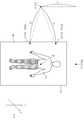
도 1은 본 발명의 일 실시예에 따른 의료 영상 촬영 장치(100)를 도시하는 도면이다. 도 1은 의료 영상 촬영 장치(100)의 예시로서 MRI 장치를 도시하고 있다.1 is a view showing a medical
의료 영상 촬영 장치(100)는 대상체(10)를 지지하는 테이블(110)과 테이블(110)에 위치한 대상체(10)가 내부에 위치하게 되는 갠트리(105)를 포함한다.A medical
대상체(10)의 의료 영상을 촬영하기 위해서는 대상체(10)의 촬영 부위 또는 촬영 지점(B)이 갠트리(105) 내부의 기준 지점(A), 예를 들어, 갠트리(105) 내부의 중앙 지점에 위치하여야 한다. 대상체(10)의 촬영 부위는 다양하기 때문에 사용자(20)가 대상체(10)의 촬영 부위 또는 촬영 지점(B)의 위치를 의료 영상 촬영 장치(100)에게 인식시켜야 한다.In order to photograph the medical image of the
종래에는, 고정된 지점에 위치한 레이저에 의해 레이저 신호가 조사되는 지점에 대상체(10)의 촬영 지점(B)을 위치시킴으로써 의료 영상 촬영 장치(100)에 촬영 지점(B)을 설정하였다. 그러나, 이러한 방법은 대상체(10)의 촬영 지점(B)을 레이저 신호가 조사되는 지점에 위치시키기 위해 사용자(20)가 테이블(110)의 위치를 수동적으로 조절하여야 한다는 불편함이 존재하였다.Conventionally, the photographing point B is set in the medical
또한, 종래에는, 테이블(110)을 복수 개의 영역으로 구분하고 사용자(20)가 복수 개의 영역 중 어느 하나의 영역을 촬영 지점(B)으로 선택함으로써 촬영 지점(B)의 위치를 의료 영상 촬영 장치(100)에 설정하였다. 그러나, 이러한 방법은 대상체(10)의 촬영 지점(B)을 정확하게 설정하기 못한다는 문제점이 존재하였다.Conventionally, the table 110 is divided into a plurality of areas, and the
본 발명의 일 실시예에 따른 의료 영상 촬영 장치(100)는 복수 개의 감지부(200)와 사용자(20)에 의해 조작되는 인디케이터(300)를 이용하여 대상체(10)의 촬영 지점(B)을 설정할 수 있다. 즉, 사용자(20)는 대상체(10)의 테이블(110)의 위치를 수동적으로 조작할 필요없이 무선 인디케이터(300)를 이용하여 대상체(10)의 촬영 지점(B)을 편리하고 정밀하게 설정할 수 있다.The medical
한편, 도 1은 복수 개의 감지부(200)가 테이블(110)에 부착되어 있는 것으로 도시하고 있지만, 이는 하나의 예시일 뿐이며, 복수 개의 감지부(200)는 천장 또는 바닥과 연결된 부재에 연결될 수도 있다.1 shows that a plurality of sensing
또한, 도 1은 MRI 장치를 도시하고 있지만, 복수의 감지부(200) 및 인디케이터(300)를 이용하여 촬영 지점(B)을 설정하는 방법은 CT 장치에도 자명하게 적용될 수 있다.Although FIG. 1 shows the MRI apparatus, the method of setting the photographing point B using the plurality of sensing
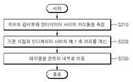
도 2는 본 발명의 일 실시예에 따른 테이블(110)의 위치 조절 방법의 순서를 도시하는 순서도이다.2 is a flowchart showing a procedure of a position adjustment method of the table 110 according to an embodiment of the present invention.
S210 단계에서, 의료 영상 촬영 장치(100)는 제 1 축을 따라 배치된 복수의 감지부(200) 각각과 사용자에 의해 임의의 지점에 위치된 인디케이터(300) 사이의 거리들을 측정한다. 예를 들어, 제 1 감지부와 제 2 감지부가 Y 축을 따라 의료 영상 촬영 장치(100)에 연결되어 있고, 사용자가 임의의 위치에서 인디케이터(300)를 파지하고 있는 경우, 의료 영상 촬영 장치(100)는 제 1 감지부와 인디케이터(300) 사이의 거리, 제 2 감지부와 인디케이터(300) 사이의 거리를 측정할 수 있다.In step S210, the
의료 영상 촬영 장치(100)는 다양한 방법으로 감지부(200)와 인디케이터(300)사이의 거리를 측정할 수 있다. 예를 들어, 의료 영상 촬영 장치(100)는 감지부(200)로 하여금 인디케이터(300)로 거리 측정용 신호를 송신하게 하고, 인디케이터(300)로부터 거리 측정용 신호를 수신하게 한 후, 거리 측정용 신호의 송수신 소요 시간을 측정한다. 다음으로, 의료 영상 촬영 장치(100)는 거리 측정용 신호의 송수신 소요 시간과 거리 측정용 신호의 속력을 이용하여 감지부(200)와 인디케이터(300) 사이의 거리를 측정할 수 있다. 거리 측정용 신호는 적외선 신호, 초음파 신호, RF 신호 등을 포함할 수 있다.The
감지부(200)는 RFID 리더기(reader)를 포함할 수 있고, 인디케이터(300)는 RFID 태그(tag)를 포함할 수 있다. RFID 리더기는 RF 신호를 방출하고, RFID 태그가 RF 신호에 대한 응답으로 반사하는 RF 신호를 수신하여 RFID 태그를 인식할 수 있다. 의료 영상 촬영 장치(100)는 RFID 리더기에 의해 RF 신호가 방출된 때로부터 RFID 태그가 반사하는 RF 신호를 RFID 리더기가 수신할 때까지 걸리는 시간과, RF 신호의 속력을 이용하여 RFID 리더기와 RFID 태그 사이의 거리를 측정할 수 있다.The
S220 단계에서, 의료 영상 촬영 장치(100)는 복수의 감지부(200) 각각과 인디케이터(300) 사이의 거리들과, 사용자에 의해 기 설정된 기준 지점에 대한 복수의 감지부(200)들 각각의 상대적인 위치를 이용하여 상기 기준 지점과 인디케이터(300) 사이의 제 1 축 상의 거리(이하, 제 1 축 거리)를 계산한다. 제 1 축을 Y 축이라 한다면, 제 1 축 거리는 인디케이터(300)가 기준 지점으로부터 Y 축을 따라 얼마나 이격되어 있는지를 나타낸다. 제 1 축 거리를 계산하는 방법에 대해서는 도 3을 참조하여 후술된다.In step S220, the medical
S230 단계에서, 의료 영상 촬영 장치(100)는 제 1 축 거리에 기초하여 테이블(110)을 의료 영상 촬영 장치(100)의 갠트리(105) 내부로 이동시킨다.In step S230, the medical
하기에서 설명할 바와 같이, 본 발명의 일 실시예에 따른 의료 영상 촬영 장치(100)의 사용자(20)는 기준 지점으로부터 제 1 축 거리만큼 이격된 지점에 인디케이터(300)를 위치시키기만 하면 대상체(10)의 촬영 지점을 설정할 수 있으므로, 종래 방법에 비해 매우 간편하게 촬영 지점을 설정할 수 있다.As described below, the
도 3은 촬영 지점을 설정하는 예시적인 방법을 설명하기 위한 도면이다.3 is a diagram for explaining an exemplary method of setting a photographing point.
제 1 감지부는 제 1 축(30) 상의 D1에 위치하고, 제 2 감지부는 제 1 축(30) 상의 D2에 위치하고 있다. 제 1 축(30)은 Y 축일 수 있다. Y 축 상에 위치하는 지점들의 X 축 좌표와 Z 축 좌표는 모두 동일하므로, D1과 D2의 Y 축 좌표는 b1과 b2로 서로 상이하지만, X 축 좌표와 Z 축 좌표는 a1 및 c1으로 동일하다.The first sensing portion is located at D1 on the
기준 지점은 A에 위치한다. 기준 지점의 위치는 사용자에 의해 미리 결정된다. 인디케이터(300)는 I에 위치한다.The reference point is located at A. The position of the reference point is predetermined by the user.
전술한 바와 같이, 제 1 감지부와 제 2 감지부 각각은 인디케이터(300)와의 이격 거리를 측정한다. D1과 I 사이의 거리는 r1이고, D2와 I 사이의 거리는 r2이다.As described above, each of the first sensing unit and the second sensing unit measures a separation distance from the
의료 영상 촬영 장치(100)는, D1과 I 사이의 거리(r1), D2와 I 사이의 거리(r2) 및 A에 대한 D1과 D2의 상대적인 위치에 기초하여 A와 I 사이의 제 1 축 거리(d)를 계산할 수 있다. A에 대한 D1과 D2의 상대적인 위치는, A에 대한 D1의 좌표(a1, b1, c1)와 D2의 좌표(a1, b2, c1)을 의미한다.The
D1과 I 사이의 거리 r1은 다음의 수학식 1로 표현될 수 있고, D2와 I 사이의 거리 r2는 다음의 수학식 2로 표현될 수 있다.The distance r1 between D1 and I can be expressed by the following equation (1), and the distance r2 between D2 and I can be expressed by the following equation (2).
[수학식 1][Equation 1]
r12 = (a1-x)2 + (b1-y)2 + (c1-z)2
r1 2 = (a1-x) 2 + (b1-y) 2 + (c1-z) 2
[수학식 2]&Quot; (2) "
r22 = (a1-x)2 + (b2-y)2 + (c1-z)2
r22 = (a1-x)2 + (b2-y)2 + (c1-z)2
수학식 2에서 수학식 1을 빼면 하기의 수학식 3이 도출된다.Subtracting the equation (1) from the equation (2) yields the following equation (3).
[수학식 3]&Quot; (3) "
r22- r12 = (b2-y)2 + (b1-y)2
r22 - r12 = (b2-y)2 + (b1-y)2
수학식 3에서 r1, r2, b1, b2는 이미 알고 있는 값이므로, I의 y 좌표는 수학식 3으로부터 획득될 수 있다. 마지막으로, A의 Y 축 상의 좌표는 b이므로, A와 I 사이의 제 1 축 길이 d는 b에서 y를 뺌으로써 계산될 수 있다.Since r1, r2, b1, and b2 in equation (3) are known values, the y coordinate of I can be obtained from equation (3). Finally, since the coordinate on the Y axis of A is b, the first axis length d between A and I can be calculated by subtracting y from b.
의료 영상 촬영 장치(100)는 기준 지점(A)으로부터 제 1 축 길이(d)만큼 이격된 대상체(10) 상의 지점(B)을 촬영 지점으로 설정할 수 있다. 다음에, 의료 영상 촬영 장치(100)는 테이블(110)을 갠트리(105) 내부로 이동시켜 촬영 지점(B)이 기준 지점(A)에 위치하게 할 수 있다.The
일반적인 MRI 장치에서는 테이블(110)이 X 축 또는 Z 축을 따라 이동할 수 없기 때문에, 테이블(110)의 Y축 상의 위치가 중요하다. 즉, 본 발명의 의료 영상 촬영 장치(100)의 사용자는 촬영 지점의 x 축 상의 위치와 z 축 상의 위치는 고려하지 않고, y축 상의 위치만을 고려하여 인디케이터(300)를 위치시킴으로써, 촬영 지점을 간편하게 설정할 수 있다.In a general MRI apparatus, since the table 110 can not move along the X axis or the Z axis, the position of the table 110 on the Y axis is important. In other words, the user of the
도 4는 본 발명의 다른 실시예에 따른 테이블(110)의 위치 조절 방법의 순서를 도시하는 순서도이다. 4 is a flowchart showing a procedure of a position adjustment method of the table 110 according to another embodiment of the present invention.
S410 단계에서, 의료 영상 촬영 장치(100)는 사용자로부터 인디케이터(300)를 통해 촬영 지점 설정 요청을 수신한다. 사용자는 촬영 지점을 설정하기 위해 임의의 지점에 인디케이터(300)를 위치시킨 후, 인디케이터(300)에 구비된 사용자 입력부를 통해 촬영 지점 설정 요청을 의료 영상 촬영 장치(100)로 전송할 수 있다.In step S410, the
S420 단계에서, 의료 영상 촬영 장치(100)는 복수의 감지부(200) 각각과 인디케이터(300) 사이의 거리들을 측정하고, S430 단계에서, 의료 영상 촬영 장치(100)는 기준 지점과 인디케이터(300) 사이의 제 1 축 거리를 계산한다. 의료 영상 촬영 장치(100)가 복수의 감지부(200) 각각과 인디케이터(300) 사이의 거리들을 측정하는 방법 및 기준 지점과 인디케이터(300) 사이의 제 1 축 거리를 계산하는 방법에 대해서는 전술하였는바, 상세한 설명을 생략한다.In step S420, the
S440 단계에서, 의료 영상 촬영 장치(100)는 기준 지점으로부터 제 1 축 거리만큼 이격된 대상체(10) 상의 지점을 촬영 지점으로 설정한다.In step S440, the medical
S450 단계에서, 의료 영상 촬영 장치(100)는 촬영 지점의 설정이 완료되었음을 나타내는 메시지를 인디케이터(300)로 전송한다.In step S450, the
S460 단계에서, 의료 영상 촬영 장치(100)는 사용자로부터 테이블(110)의 이동 요청을 인디케이터(300)를 통해 수신한다. 사용자는 인디케이터(300)에 구비된 사용자 입력부를 통해 테이블 이동 요청을 의료 영상 촬영 장치(100)로 전송할 수 있다.In step S460, the medical
S470 단계에서, 의료 영상 촬영 장치(100)는 제 1 축 거리에 기초하여 테이블(110)을 갠트리(105) 내부로 이동시킨다.In step S470, the
본 실시예에 따르면, 사용자는 인디케이터(300)를 이용하여 촬영 지점의 설정 및 테이블의 이동을 모두 제어할 수 있으므로, 사용자 편의성이 더욱 향상될 수 있다.According to the present embodiment, since the user can control both the setting of the shooting point and the movement of the table using the
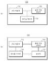
도 5는 본 발명의 또 다른 실시예에 따른 테이블(110)의 위치 조절 방법의 순서를 도시하는 순서도이다.5 is a flowchart showing a procedure of a position adjustment method of the table 110 according to another embodiment of the present invention.
S510 단계에서, 의료 영상 촬영 장치(100)는 제 1 축과 상이한 제 2 축을 따라 배치된 복수의 제 2 감지부 각각과 인디케이터(300) 사이의 거리들을 측정한다. 제 2 축과 제 1 축은 서로 수직일 수 있다. 복수의 제 2 감지부들 중 어느 하나의 제 2 감지부는 도 2에서 설명한 복수의 감지부들 중 어느 하나의 감지부와 동일한 감지부일 수 있다. 즉, 제 1 축을 따라 배치된 복수의 감지부들 중 어느 하나의 감지부는 동시에 제 2 축을 따라 배치된 제 2 감지부일 수 있다.In step S510, the
S520 단계에서, 의료 영상 촬영 장치(100)는, 복수의 제 2 감지부 각각과 인디케이터(300) 사이의 거리들과, 기준 지점에 대한 복수의 감지부들 각각의 상대적인 위치를 이용하여, 기준 지점과 인디케이터(300) 사이의 제 2 축 상의 거리(이하, 제 2 축 거리)를 계산한다. 의료 영상 촬영 장치(100)가 제 2 축 거리를 계산하는 방법에 대해서는 도 6을 참조하여 상세히 설명한다.In step S520, the medical
S530 단계에서, 의료 영상 촬영 장치(100)는 제 2 축 상의 거리에 기초하여 테이블(110)의 높이를 조절한다. CT 장치 또는 테이블(110)의 높이가 조절되는 MRI 장치의 경우, 촬영 지점의 높이를 갠트리(105) 내부의 기준 지점의 높이에 일치시키는 것이 이미지의 퀄리티를 확보하는데, 그리고 대상체(10)에 대한 엑스선의 피폭량을 조절하는데 매우 중요하다.In step S530, the
도 6은 촬영 지점을 설정하는 예시적인 방법을 설명하기 위한 도면이다.6 is a diagram for explaining an exemplary method of setting a shooting point.
제 2-1 감지부는 Z 축 상의 D1에 위치하고, 제 2-2 감지부는 Z 축 상의 D2에 각각 위치한다. Z 축 상에 위치하는 지점들의 X 축 좌표와 Y 축 좌표는 모두 동일하다. 따라서, D1과 D2의 Z 축 좌표는 c1과 c2로 서로 상이하지만, X 축 좌표와 Y 축 좌표는 각각 a1 및 b1으로 서로 동일하다.The 2-1th sensing unit is located on D1 on the Z axis, and the 2-2 sensing unit is located on D2 on the Z axis, respectively. The X-axis coordinate and the Y-axis coordinate of the points located on the Z-axis are all the same. Therefore, the Z-axis coordinates of D1 and D2 are different from each other between c1 and c2, but the X-axis coordinate and the Y-axis coordinate are the same as a1 and b1, respectively.
기준 지점은 A에 위치한다. 기준 지점의 위치는 사용자에 의해 미리 결정된다. 인디케이터(300)는 I에 위치한다.The reference point is located at A. The position of the reference point is predetermined by the user.
전술한 바와 같이, 제 2-1 감지부와 인디케이터(300) 사이의 거리 및 제 2-2 감지부와 인디케이터(300) 사이의 거리가 측정된다. D1과 I 사이의 거리는 r1이고, D2와 I 사이의 거리는 r2이다.As described above, the distance between the second-1 sensing unit and the
의료 영상 촬영 장치(100)는, D1과 I 사이의 거리(r1), D2와 I 사이의 거리(r2) 및 A에 대한 D1과 D2의 상대적인 위치에 기초하여 A와 I 사이의 제 2 축 거리(h)를 계산할 수 있다. A에 대한 D1과 D2의 상대적인 위치는, A에 대한 D1의 좌표(a1, b1, c1)와 D2의 좌표(a1, b1, c2)를 의미한다.The
전술한 수학식 1, 수학식 2 및 수학식 3을 이용하면, I의 z 좌표가 획득될 수 있다. A의 Z 축 상의 좌표는 c이므로, A와 I 사이의 제 2 축 길이 h는 z에서 c를 뺌으로써 계산될 수 있다.Using the above-described equations (1), (2) and (3), the z coordinate of I can be obtained. Since the coordinate on the Z axis of A is c, the second axial length h between A and I can be calculated by subtracting c from z.
의료 영상 촬영 장치(100)는 기준 지점(A)으로부터 제 2 축을 따라 제 2 축 길이만큼 이격된 지점을 촬영 지점으로 설정할 수 있다. 의료 영상 촬영 장치(100)는 테이블(110)을 제 2 축을 따라 h만큼 하강시켜 인디케이터(300)의 높이와 기준 지점(A)의 높이를 일치시킬 수 있다.The medical
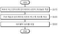
도 7(a)는 본 발명의 일 실시예에 따른 의료 영상 촬영 장치(700)의 구성을 도시하는 블록도이다.7 (a) is a block diagram showing a configuration of a medical
도 7(a)를 참조하면, 본 발명의 일 실시예에 따른 의료 영상 촬영 장치(700)는 거리 측정부(710), 촬영 지점 설정부(730) 및 테이블 제어부(750)를 포함한다. 거리 측정부(710) 및 촬영 지점 설정부(730)는 마이크로 프로세서로 구현될 수 있다.7A, a medical
거리 측정부(710)는 제 1 축을 따라 배치된 복수의 감지부(200) 각각과 사용자에 의해 임의의 지점에 위치된 인디케이터(300) 사이의 거리들을 측정한다. 거리 측정부(710)는 복수의 감지부(200) 각각으로부터 거리 측정 신호가 방출된 때로부터 복수의 감지부(200) 각각이 인디케이터(300)에 의해 반사된 거리 측정 신호를 수신할 때까지 소요되는 시간을 이용하여 복수의 감지부(200) 각각과 인디케이터(300) 사이의 거리를 측정할 수 있다. 거리 측정부(710)는 제 1 축과 상이한, 예를 들어 제 1 축과 수직 관계인 제 2 축을 따라 배치된 복수의 제 2 감지부 각각과 인디케이터(300) 사이의 거리들을 측정할 수도 있다.The
촬영 지점 설정부(730)는 복수의 감지부(200) 각각과 인디케이터(300) 사이의 거리와, 사용자에 의해 기 설정된 기준 지점에 대한 복수의 감지부(200)들 각각의 상대적인 위치를 이용하여 상기 기준 지점과 인디케이터(300) 사이의 제 1 축 상의 거리(이하, 제 1 축 거리)를 계산한다. 촬영 지점 설정부(730)는 기준 지점으로부터 제 1 축 거리만큼 이격된 대상체(10) 상의 지점을 촬영 지점으로 설정할 수 있다.The photographing
또한, 촬영 지점 설정부(730)는 복수의 제 2 감지부 각각과 인디케이터(300) 사이의 거리들, 및 기준 지점에 대한 복수의 제 2 감지부들 각각의 상대적인 위치를 이용하여, 기준 지점과 인디케이터(300) 사이의 제 2 축 상의 거리(이하, 제 2 축 거리)를 계산할 수 있다.Further, the shooting
테이블 제어부(750)는 계산된 제 1 축 거리에 기초하여, 테이블(110)을 의료 영상 획득 장치의 갠트리(105) 내부로 이동시킨다. 또한, 테이블 제어부(750)는 제 2 축 거리에 기초하여, 테이블(110)의 높이를 조절할 수도 있다.The
도 7(b)는 본 발명의 다른 실시예에 따른 의료 영상 촬영 장치(700)의 구성을 도시하는 블록도이다.7 (b) is a block diagram showing the configuration of a medical
본 발명의 다른 실시예에 따른 의료 영상 촬영 장치(700)는 도 7(a)에 도시된 의료 영상 촬영 장치(700)의 구성 이외에 통신부(770)를 더 포함할 수 있다.The medical
통신부(770)는 인디케이터(300)로부터 촬영 지점의 설정 요청을 수신하고, 촬영 지점 설정부(730)가 촬영 지점의 설정을 완료한 경우, 촬영 지점의 설정이 완료되었음을 나타내는 메시지를 인디케이터(300)로 전송할 수 있다.The
또한, 통신부(770)는 인디케이터(300)로부터 테이블(110) 이동 요청을 수신하고, 테이블(110) 이동 요청을 테이블 제어부(750)로 전달하여 테이블 제어부(750)가 테이블(110)의 위치를 조절할 수 있게 한다.The
도 8은 본 발명의 또 다른 실시예에 따른 테이블(110)의 위치 조절 방법의 순서를 도시하는 순서도이다. 도 8은 무선 인디케이터(300)에 의해 수행되는 테이블(110)의 위치 조절 방법을 나타낸다.8 is a flowchart showing a procedure of a position adjustment method of the table 110 according to another embodiment of the present invention. 8 shows a method of adjusting the position of the table 110 performed by the
S810 단계에서, 무선 인디케이터(300)는 사용자의 제 1 입력에 기초하여, 무선 인디케이터(300)에 부착된 RFID 태그를 활성화시킨다. 무선 인디케이터(300)에 부착된 RFID 태그는 가시광선에 의해 활성화 또는 비활성화되는 RFID 태그를 포함할 수 있다. 구체적으로, 사용자가 무선 인디케이터(300)에 제 1 입력을 입력하면, 무선 인디케이터(300)는 가시광선을 RFID 태그에 조사하여 RFID 태그를 활성화시킬 수 있다. RFID 태그가 활성화되면 RFID 리더기에 의해 RFID 태그가 인식될 것이므로, 무선 인디케이터(300)는 RFID 태그를 활성화시킴으로써 의료 영상 촬영 장치(100)에게 촬영 지점의 설정 요청을 전송할 수 있다.In step S810, the
S820 단계에서, 무선 인디케이터(300)는, 의료 영상 촬영 장치(100)의 RFID 리더기를 통해 인식된 상기 무선 인디케이터(300)의 위치를 기준으로 촬영 지점의 설정이 완료되었음을 나타내는 메시지를 의료 영상 촬영 장치(100)로부터 수신할 수 있다. 전술한 바와 같이, 사용자가 임의의 지점에 무선 인디케이터(300)를 위치시키면, 의료 영상 촬영 장치(100)는 무선 인디케이터(300)와 기준 지점 사이의 제 1 축 거리를 계산함으로써, 촬영 지점을 설정할 수 있다. 다음으로, 의료 영상 촬영 장치(100)는 촬영 지점의 설정이 완료되었음을 나타내는 메시지를 무선 인디케이터(300)로 전송할 수 있다.In step S820, the
S830 단계에서, 무선 인디케이터(300)는 사용자의 제 2 입력에 기초하여, 테이블(110) 이동 요청을 의료 영상 촬영 장치(100)로 전송한다.In step S830, the
본 발명의 일 실시예에 따른 무선 인디케이터(300)는 의료 영상 촬영 장치(100)로부터 촬영 지점의 설정이 완료되었음을 나타내는 메시지를 수신한 이후에 의료 영상 촬영 장치(100)로 테이블(110) 이동 요청을 전송할 수 있다. 만약, RFID 태그를 활성화시킨 이후, 소정 시간 내에 의료 영상 촬영 장치(100)로부터 상기 메시지를 수신하지 못한 경우, 무선 인디케이터(300)는 위치의 재조정을 요청하는 메시지를 출력할 수 있다.The
RFID 리더기와 RFID 태그를 포함한 무선 통신 장치들은 기 설정된 통신 반경이 존재하므로, 무선 인디케이터(300)가 기 설정된 통신 반경을 벗어난 경우 위치의 재조정을 요청하는 메시지를 출력하는 것이다.Since the wireless communication devices including the RFID reader and the RFID tag have a predetermined communication radius, when the
또는, 의료 영상 촬영 장치(100)는, 기준 지점과 무선 인디케이터(300) 사이의 제 1 축 상의 거리가 기 설정된 거리를 초과하는 경우 촬영 지점의 설정을 수행하지 않을 수 있다. 예를 들어, 무선 인디케이터(300)가 제 1 축 방향을 따라 테이블(110)을 벗어난 지점에 위치하는 경우, 테이블(110) 전체가 갠트리(105) 내부로 이동하더라도 촬영 지점과 기준 지점이 일치하지 않을 수 있다. 이 경우, 의료 영상 촬영 장치(100)는 촬영 지점의 설정을 수행하지 않고, 무선 인디케이터(300)로 촬영 지점의 완료를 나타내는 메시지를 전송하지도 않는다. 이에 따라, 무선 인디케이터(300)는 위치의 재조정을 요청하는 메시지를 출력할 수 있다.Alternatively, the
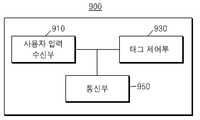
도 9는 본 발명의 일 실시예에 따른 무선 인디케이터(900)의 구성을 도시하는 블록도이다.9 is a block diagram illustrating a configuration of a
도 9를 참조하면, 본 발명의 일 실시예에 따른 무선 인디케이터(900)는 사용자 입력 수신부(910), 태그 제어부(930) 및 통신부(950)를 포함할 수 있다.9, the
사용자 입력 수신부(910)는 사용자로부터 소정의 입력을 수신한다. 사용자 입력 수신부(910)는 음성 인식부, 지문 인식부, 제스처 인식부, 안구 인식부 등 사용자로부터 소정의 입력을 수신하는 장치를 포함할 수 있다.The user
태그 제어부(930)는 사용자의 제 1 입력에 기초하여, 무선 인디케이터(900)에 부착된 RFID 태그를 활성화 또는 온(On) 시킨다.The
통신부(950)는, 의료 영상 촬영 장치(100)의 RFID 리더기를 통해 인식된 무선 인디케이터(900)의 위치를 기준으로 촬영 지점의 설정이 완료되었음을 나타내는 메시지를 의료 영상 촬영 장치(100)로부터 수신하고, 사용자의 제 2 입력에 기초하여, 테이블(110) 이동 요청을 의료 영상 촬영 장치(100)로 전송한다.The
도 9에는 도시되지 않았지만, 본 발명의 일 실시예에 따른 무선 인디케이터(900)는 RFID 태그를 활성화시킨 이후, 소정 시간 내에 의료 영상 촬영 장치(100)로부터 촬영 지점의 설정이 완료되었음을 나타내는 메시지를 수신하지 못한 경우, 무선 인디케이터(900)의 위치의 재조정을 요청하는 메시지를 출력하는 출력부를 더 포함할 수 있다.Although not shown in FIG. 9, the
또한, 본 발명의 일 실시예에 따른 무선 인디케이터(900)는 직선 방향으로 광을 조사하는 광 포인터부(미도시)를 더 포함할 수 있는데, 사용자는 광 포인터부에 의해 조사된 광을 이용하여 무선 인디케이터(900)가 대상체의 어느 지점을 가리키고 있는지를 확인할 수 있다. 사용자는 광 포인터부를 이용하여 촬영 지점을 보다 정확하게 설정할 수 있다.In addition, the
도 10은 본 발명의 일 실시예에 따른 무선 인디케이터(1000)를 도시하는 도면이다.10 is a diagram illustrating a
도 10에 도시된 바와 같이, 무선 인디케이터(1000)는 사용자 입력부(1010), RFID 태그(1030), 출력부(1070), 광 조사부(1050) 및 RFID 태그에 대한 물리적인 충격을 보호하는 RFID 태그 캡(cap)(1090)을 포함할 수 있다.10, the
사용자 입력부(1010)는 버튼 구조로 구성되며, 사용자는 버튼을 눌러 소정의 제어 명령을 입력할 수 있다. 사용자는 사용자 입력부(1010) 중 촬영 지점 설정 버튼을 눌러 광 조사부(1050)를 통해 광이 RFIF 태그(1030)에 조사되도록 할 수 있다. 이에 의해, RFID 태그가 활성화된다.The
무선 인디케이터(1000)는 의료 영상 촬영 장치(100)로부터 촬영 지점의 설정이 완료되었음을 나타내는 메시지를 수신한 경우, 이를 출력부(1070)를 통해 출력하고, RFID 태그(1030)가 활성화된 이후 소정 시간 내에 상기 메시지가 수신되지 않은 경우 출력부(1070)를 통해 무선 인디케이터(1000)의 위치 재조정을 요청하는 메시지를 출력할 수 있다.When the
사용자는 출력부(1070)에 촬영 지점의 설정이 완료되었다는 메시지가 출력된 경우, 사용자 입력부(1010) 중 테이블 이동 버튼을 눌러 의료 영상 촬영 장치(100)로 테이블 이동 요청이 전송되도록 할 수 있다.When a message indicating that the setting of the photographing point is completed is output to the
도 10에는 도시되지 않았지만, 본 발명의 일 실시예에 따른 무선 인디케이터(1000)는 직선 방향으로 광을 조사하는 광 포인터부를 더 포함할 수 있다. 광 포인터부에 의해 방출되는 광은 RFID 태그 캡(1090)을 통해 직선으로 조사되어 사용자가 대상체의 어느 부분을 가리키고 있는지를 표시할 수 있다.Although not shown in FIG. 10, the
도 11은 본 발명의 또 다른 실시예에 따른 의료 영상 촬영 장치(1100)의 구성을 도시하는 블록도이다. 도 11은 의료 영상 촬영 장치(1100)로서, MRI 장치를 도시하고 있다.11 is a block diagram showing a configuration of a medical
도 11을 참조하면, MRI 장치(1100)는 갠트리(gantry)(1110), 신호 송수신부(1130), 모니터링부(1150), 시스템 제어부(1170) 및 오퍼레이팅부(1190)를 포함할 수 있다.Referring to FIG. 11, the
갠트리(1110)는 주 자석(1112), 경사 코일(1113), 고정식 RF 코일(1114) 및 착탈식 RF 코일(1115) 등에 의하여 생성된 전자파가 외부로 방사되는 것을 차단한다. 갠트리(1110) 내 보어(bore)에는 정자기장 및 경사자장이 형성되며, 대상체(10)를 향하여 RF 신호가 조사된다.The
주 자석(1112), 경사 코일(1113) 및 고정식 RF 코일(1114)은 갠트리(1110)의 소정의 방향을 따라 배치될 수 있다. 소정의 방향은 동축 원통 방향 등을 포함할 수 있다. 원통의 수평축을 따라 원통 내부로 삽입 가능한 테이블(1116)상에 대상체(10)가 위치될 수 있다.The
주 자석(1112)은 대상체(10)에 포함된 원자핵들의 자기 쌍극자 모멘트(magnetic dipole moment)의 방향을 일정한 방향으로 정렬하기 위한 정자기장 또는 정자장(static magnetic field)을 생성한다. 주 자석에 의하여 생성된 자장이 강하고 균일할수록 대상체(10)에 대한 비교적 정밀하고 정확한 MR 영상을 획득할 수 있다.The
경사 코일(Gradient coil)(1113)은 서로 직교하는 X축, Y축 및 Z축 방향의 경사자장을 발생시키는 X, Y, Z 코일을 포함한다. 경사 코일(1113)은 대상체(10)의 부위 별로 공명 주파수를 서로 다르게 유도하여 대상체(10)의 각 부위의 위치 정보를 제공할 수 있다.The
고정식 RF 코일(1114)과 착탈식 RF 코일(1115)은 환자에게 RF 신호를 조사하고, 환자로부터 방출되는 MR 신호를 수신할 수 있다. 구체적으로, 고정식 RF 코일(1114)과 착탈식 RF 코일(1115)은, 세차 운동을 하는 원자핵을 향하여 세차운동의 주파수와 동일한 주파수의 RF 신호를 환자에게 전송한 후 RF 신호의 전송을 중단하고, 환자로부터 방출되는 MR 신호를 수신할 수 있다.The
예를 들어, 고정식 RF 코일(1114)과 착탈식 RF 코일(1115)은 어떤 원자핵을 낮은 에너지 상태로부터 높은 에너지 상태로 천이시키기 위하여 이 원자핵의 종류에 대응하는 무선 주파수(Radio Frequency)를 갖는 전자파 신호, 예컨대 RF 신호를 생성하여 대상체(10)에 인가할 수 있다. 고정식 RF 코일(1114)과 착탈식 RF 코일(1115)에 의해 생성된 전자파 신호가 어떤 원자핵에 가해지면, 이 원자핵은 낮은 에너지 상태로부터 높은 에너지 상태로 천이될 수 있다. 이후에, 고정식 RF 코일(1114)과 착탈식 RF 코일(1115)에 의해 생성된 전자파가 사라지면, 전자파가 가해졌던 원자핵은 높은 에너지 상태로부터 낮은 에너지 상태로 천이하면서 라모어 주파수를 갖는 전자파를 방사할 수 있다. 다시 말해서, 원자핵에 대하여 전자파 신호의 인가가 중단되면, 전자파가 가해졌던 원자핵에서는 높은 에너지에서 낮은 에너지로의 에너지 준위의 변화가 발생하면서 라모어 주파수를 갖는 전자파가 방사될 수 있다. 고정식 RF 코일(1114)과 착탈식 RF 코일(1115)은 대상체(10) 내부의 원자핵들로부터 방사된 전자파 신호를 수신할 수 있다.For example, the
고정식 RF 코일(1114)과 착탈식 RF 코일(1115)은 원자핵의 종류에 대응하는 무선 주파수를 갖는 전자파를 생성하는 기능과 원자핵으로부터 방사된 전자파를 수신하는 기능을 함께 갖는 하나의 RF 송수신 코일로서 구현될 수도 있다. 또한, 원자핵의 종류에 대응하는 무선 주파수를 갖는 전자파를 생성하는 기능을 갖는 송신 RF 코일과 원자핵으로부터 방사된 전자파를 수신하는 기능을 갖는 수신 RF 코일로서 각각 구현될 수도 있다.The fixed
착탈식 RF 코일(1115)은 머리 RF 코일, 흉부 RF 코일, 다리 RF 코일, 목 RF 코일, 어깨 RF 코일, 손목 RF 코일, 다리 RF 코일 및 발목 RF 코일 등을 포함한 대상체의 일부분에 대한 RF 코일을 포함할 수 있다.The removable RF coil 1115 includes an RF coil for a portion of the object including a head RF coil, a thorax RF coil, a leg RF coil, a neck RF coil, a shoulder RF coil, a wrist RF coil, a leg RF coil, and an ankle RF coil. can do.
착탈식 RF 코일(1115)은 유선 및/또는 무선으로 외부 장치와 통신할 수 있으며, 통신 주파수 대역에 따른 듀얼 튠(dual tune) 통신도 수행할 수 있다.The removable RF coil 1115 can communicate with an external device by wire and / or wireless, and can also perform dual tune communication according to a communication frequency band.
또한, 착탈식 RF 코일(1115)은 코일의 구조에 따라 새장형 코일(birdcage coil), 표면 부착형 코일(surface coil) 및 횡전자기파 코일(TEM 코일)을 포함할 수 있다.The removable RF coil 1115 may include a birdcage coil, a surface coil, and a transverse electromagnetic coil (TEM coil) according to the structure of the coil.
또한, 착탈식 RF 코일(1115)은 용도에 따라, 송신 전용 코일, 수신 전용 코일 및 송/수신 겸용 코일을 포함할 수 있다.Also, the removable RF coil 1115 may include a transmission-only coil, a reception-only coil, and a transmission / reception combination coil, depending on the use.
또한, 착탈식 RF 코일(1115)은 채널 수에 따라 16 채널, 32 채널, 72채널 및 144 채널 등 다양한 채널의 RF 코일을 포함할 수 있다.Also, the removable RF coil 1115 may include RF coils of various channels such as 16 channels, 32 channels, 72 channels, and 144 channels depending on the number of channels.
갠트리(1110)는 갠트리(1110)의 외측에 위치하는 디스플레이(1117)와 갠트리(1110)의 내측에 위치하는 디스플레이(미도시)를 더 포함할 수 있다.The
신호 송수신부(1130)는 소정의 MR 시퀀스에 따라 갠트리(1110) 내부, 즉 보어에 형성되는 경사자장을 제어하고, RF 신호와 MR 신호의 송수신을 제어할 수 있다.The signal transmitting and receiving
신호 송수신부(1130)는 경사자장 증폭기(1132), 송수신 스위치(1134), RF 송신부(1136) 및 MR 수신부(1138)를 포함할 수 있다.The signal transmitting and receiving
경사자장 증폭기(Gradient Amplifier)(1132)는 갠트리(1110)에 포함된 경사 코일(1113)을 구동시키며, 경사자장 제어부(1174)의 제어 하에 경사자장을 발생시키기 위한 펄스 신호를 경사 코일(1113)에 공급할 수 있다. 경사자장 증폭기(1132)로부터 경사 코일(1113)에 공급되는 펄스 신호를 제어함으로써, X축, Y축, Z축 방향의 경사 자장이 합성될 수 있다.The gradient
RF 송신부(1136) 및 MR 수신부(1138)는 고정식 RF 코일(1114)과 착탈식 RF 코일(1115)을 구동시킬 수 있다. RF 송신부(1136)는 라모어 주파수의 RF 펄스를 고정식 RF 코일(1114)과 착탈식 RF 코일(1115)에 공급하고, MR 수신부(1138)는 고정식 RF 코일(1114)과 착탈식 RF 코일(1115)이 수신한 MR 신호를 수신할 수 있다.The
송수신 스위치(1134)는 RF 신호와 MR 신호의 송수신 방향을 조절할 수 있다. 예를 들어, 송신 모드 동안에 고정식 RF 코일(1114)과 착탈식 RF 코일(1115)을 통하여 대상체(10)로 RF 신호가 조사되게 하고, 수신 모드 동안에는 고정식 RF 코일(1114)과 착탈식 RF 코일(1115)을 통하여 대상체(10)로부터의 MR 신호가 수신되게 할 수 있다. 이러한 송수신 스위치(1134)는 RF 제어부(1176)로부터의 제어 신호에 의하여 제어될 수 있다.The transmission /
모니터링부(1150)는 갠트리(1110) 또는 갠트리(1110)에 장착된 기기들을 모니터링 또는 제어할 수 있다. 모니터링부(1150)는 시스템 모니터링부(1152), 대상체 모니터링부(1154), 테이블 제어부(1156) 및 디스플레이 제어부(1158)를 포함할 수 있다.The
시스템 모니터링부(1152)는 정자기장의 상태, 경사자장의 상태, RF 신호의 상태, RF 코일의 상태, 테이블의 상태, 대상체의 신체 정보를 측정하는 기기의 상태, 전원 공급 상태, 열 교환기의 상태, 컴프레셔의 상태 등을 모니터링하고 제어할 수 있다.The system monitoring unit 1152 monitors the state of the static magnetic field, the state of the inclined magnetic field, the state of the RF signal, the state of the RF coil, the state of the table, the state of the device for measuring the body information of the object, You can monitor and control the state of the compressor.
대상체 모니터링부(1154)는 대상체(10)의 상태를 모니터링한다. 구체적으로, 대상체 모니터링부(1154)는 대상체(10)의 움직임 또는 위치를 관찰하기 위한 카메라, 대상체(10)의 호흡을 측정하기 위한 호흡 측정기, 대상체(10)의 심전도를 측정하기 위한 ECG 측정기, 또는 대상체(10)의 체온을 측정하기 위한 체온 측정기를 포함할 수 있고, 호흡 측정기, ECG 측정기, 체온 측정기 등은 갠트리(1110)에 착탈될 수 있다.The object monitoring unit 1154 monitors the state of the
테이블 제어부(1156)는 대상체(10)가 위치하는 테이블(1116)의 이동을 제어한다. 테이블 제어부(1156)는 시퀀스 제어부(1172)의 시퀀스 제어에 따라 테이블(1116)의 이동을 제어할 수도 있다. 예를 들어, 대상체의 이동 영상 촬영(moving imaging)에 있어서, 테이블 제어부(1156)는 시퀀스 제어부(1172)에 의한 시퀀스 제어에 따라 지속적으로 또는 단속적으로 테이블(1116)을 이동시킬 수 있으며, 이에 의해, 갠트리의 FOV(field of view)보다 큰 FOV로 대상체를 촬영할 수 있다.The table control unit 1156 controls the movement of the table 1116 in which the
또한, 테이블 제어부(1156)는 촬영 지점 설정부(1196)에 의해 계산된 제 1 축 거리와 제 2 축 거리에 기초하여, 테이블(1116)을 갠트리(1110) 내부로 이동시킬 수 있고, 테이블(1116)의 높이를 조절할 수도 있다.The table control unit 1156 can move the table 1116 into the
디스플레이 제어부(1158)는 갠트리(1110)의 외측 및 내측에 위치하는 디스플레이를 제어한다. 구체적으로, 디스플레이 제어부(1158)는 갠트리(1110)의 외측 및 내측에 위치하는 디스플레이의 온/오프 또는 디스플레이에 출력될 화면 등을 제어할 수 있다. 또한, 갠트리(1110) 내측 또는 외측에 스피커가 위치하는 경우, 디스플레이 제어부(1158)는 스피커의 온/오프 또는 스피커를 통해 출력될 사운드 등을 제어할 수도 있다.The display control unit 1158 controls the displays located outside and inside the
시스템 제어부(1170)는 갠트리(1110) 내부에서 형성되는 신호들의 시퀀스를 제어하는 시퀀스 제어부(1172), 및 갠트리(1110)와 갠트리(1110)에 장착된 기기들을 제어하는 갠트리 제어부(1178)를 포함할 수 있다.The
시퀀스 제어부(1172)는 경사자장 증폭기(1132)를 제어하는 경사자장 제어부(1174), 및 RF 송신부(1136), MR 수신부(1138) 및 송수신 스위치(1134)를 제어하는 RF 제어부(1176)를 포함할 수 있다.The
시퀀스 제어부(1172)는 오퍼레이팅부(1190)로부터 수신된 펄스 시퀀스에 따라 경사자장 증폭기(1132), RF 송신부(1136), MR 수신부(1138) 및 송수신 스위치(1134)를 제어할 수 있다. 여기에서, 펄스 시퀀스(pulse sequence)란, 경사자장 증폭기(1132), RF 송신부(1136), MR 수신부(1138) 및 송수신 스위치(1134)를 제어하기 위해 필요한 모든 정보를 포함하며, 예를 들면 경사 코일(1113)에 인가하는 펄스(pulse) 신호의 강도, 인가 시간, 인가 타이밍(timing) 등에 관한 정보 등을 포함할 수 있다.The
오퍼레이팅부(1190)는 시스템 제어부(1170)에 펄스 시퀀스 정보를 지령하는 것과 동시에, MRI 장치(1100) 전체의 동작을 제어할 수 있다.The
오퍼레이팅부(1190)는 입력부(1192), 거리 측정부(1194), 촬영 지점 설정부(1196), 영상 처리부(1197) 및 출력부(1199)를 포함할 수 있다.The
사용자는 입력부(1192)를 이용하여 대상체 정보, 파라미터 정보, 스캔 조건, 펄스 시퀀스, 화상 합성이나 차분의 연산에 관한 정보 등을 입력할 수 있다. 입력부(1192)는 키보드, 마우스, 트랙볼, 음성 인식부, 제스처 인식부, 터치 스크린 등을 포함할 수 있고, 기타 당업자에게 자명한 범위 내에서 다양한 입력 장치들을 포함할 수 있다.The user can input object information, parameter information, scan conditions, pulse sequences, information on image synthesis and calculation of difference, etc., using the
거리 측정부(1194)는 제 1 축을 따라 배치된 복수의 감지부 각각과 사용자에 의해 임의의 지점에 위치된 인디케이터 사이의 거리들을 측정한다. 거리 측정부(1194)는 복수의 감지부 각각으로부터 거리 측정 신호가 방출된 때로부터 복수의 감지부 각각이 인디케이터에 의해 반사된 거리 측정 신호를 수신할 때까지 소요되는 시간을 이용하여 복수의 감지부 각각과 인디케이터 사이의 거리를 측정할 수 있다. 거리 측정부(1194)는 제 1 축과 상이한, 예를 들어 제 1 축과 수직 관계인 제 2 축을 따라 배치된 복수의 제 2 감지부 각각과 인디케이터 사이의 거리들을 측정할 수도 있다.The
촬영 지점 설정부(1196)는 복수의 감지부(200) 각각과 인디케이터 사이의 거리와, 사용자에 의해 기 설정된 기준 지점에 대한 복수의 감지부(200)들 각각의 상대적인 위치를 이용하여 상기 기준 지점과 인디케이터 사이의 제 1 축 상의 거리(이하, 제 1 축 거리)를 계산한다. 촬영 지점 설정부(1196)는 기준 지점으로부터 제 1 축 거리만큼 이격된 대상체 상의 지점을 촬영 지점으로 설정할 수 있다.The shooting
또한, 촬영 지점 설정부(1196)는 복수의 제 2 감지부 각각과 인디케이터 사이의 거리들, 및 기준 지점에 대한 복수의 감지부들 각각의 상대적인 위치를 이용하여, 기준 지점과 인디케이터 사이의 제 2 축 상의 거리(이하, 제 2 축 거리)를 계산할 수 있다.Further, the shooting
영상 처리부(1197)는 MR 수신부(1138)로부터 수신되는 MR 신호를 처리하여, 대상체(10)에 대한 MR 화상 데이터를 생성할 수 있다. 영상 처리부(1197)는 MR 수신부(1138)가 수신한 MR 신호에 증폭, 주파수 변환, 위상 검파, 저주파 증폭, 필터링(filtering) 등과 같은 각종의 신호 처리를 가한다.The
영상 처리부(1197)는, 예를 들어, 메모리의 k 공간 (예컨대, 푸리에(Fourier) 공간 또는 주파수 공간이라고도 지칭됨)에 디지털 데이터를 배치하고, 이러한 데이터를 2차원 또는 3차원 푸리에 변환을 하여 화상 데이터로 재구성할 수 있다.The
또한, 영상 처리부(1197)는 필요에 따라, 화상 데이터(data)의 합성 처리나 차분 연산 처리 등도 수행할 수 있다. 합성 처리는, 픽셀에 대한 가산 처리, 최대치 투영(MIP)처리 등을 포함할 수 있다. 또한, 영상 처리부(1197)는 재구성되는 화상 데이터뿐만 아니라 합성 처리나 차분 연산 처리가 행해진 화상 데이터를 메모리(미도시) 또는 외부의 서버에 저장할 수 있다.In addition, the
또한, 영상 처리부(1197)가 MR 신호에 대해 적용하는 각종 신호 처리는 병렬적으로 수행될 수 있다. 예를 들어, 다채널 RF 코일에 의해 수신되는 복수의 MR 신호에 신호 처리를 병렬적으로 가하여 복수의 MR 신호를 화상 데이터로 재구성할 수도 있다.In addition, various signal processes applied to the MR signal by the
출력부(1199)는 영상 처리부(1197)에 의해 생성된 화상 데이터 또는 재구성 화상 데이터를 사용자에게 출력할 수 있다. 또한, 출력부(1199)는 UI(user interface), 사용자 정보 또는 대상체 정보 등 사용자가 MRI 장치(1100)를 조작하기 위해 필요한 정보를 출력할 수 있다. 출력부(1199)는 스피커, 프린터, CRT 디스플레이, LCD 디스플레이, PDP 디스플레이, OLED 디스플레이, FED 디스플레이, LED 디스플레이, VFD 디스플레이, DLP 디스플레이, PFD 디스플레이, 3D 디스플레이, 투명 디스플레이 등을 포함할 수 있고, 기타 당업자에게 자명한 범위 내에서 다양한 출력 장치들을 포함할 수 있다.The
도 11은 신호 송수신부(1130), 모니터링부(1150), 시스템 제어부(1170) 및 오퍼레이팅부(1190)를 서로 분리된 객체로 도시하였지만, 신호 송수신부(1130), 모니터링부(1150), 시스템 제어부(1170) 및 오퍼레이팅부(1190) 각각에 의해 수행되는 기능들이 다른 객체에서 수행될 수도 있다는 것은 당업자라면 충분히 이해할 수 있을 것이다. 예를 들어, 영상 처리부(1197)는, MR 수신부(1138)가 수신한 MR 신호를 디지털 신호로 변환한다고 전술하였지만, 이 디지털 신호로의 변환은 MR 수신부(1138), 고정식 RF 코일(1114) 또는 착탈식 RF 코일(1115)이 직접 수행할 수도 있다.11 shows the signal transmission /
갠트리(1110), 고정식 RF 코일(1114), 착탈식 RF 코일(1115), 신호 송수신부(1130), 모니터링부(1150), 시스템 제어부(1170) 및 오퍼레이팅부(1190)는 서로 무선 또는 유선으로 연결될 수 있고, 무선으로 연결된 경우에는 서로 간의 클럭(clock)을 동기화하기 위한 장치(미도시)를 더 포함할 수 있다. 갠트리(1110), 고정식 RF 코일(1114), 착탈식 RF 코일(1115), 신호 송수신부(1130), 모니터링부(1150), 시스템 제어부(1170) 및 오퍼레이팅부(1190) 사이의 통신은, LVDS(Low Voltage Differential Signaling) 등의 고속 디지털 인터페이스, UART(universal asynchronous receiver transmitter) 등의 비동기 시리얼 통신, 과오 동기 시리얼 통신 또는 CAN(Controller Area Network) 등의 저지연형의 네트워크 프로토콜, 광통신 등이 이용될 수 있으며, 당업자에게 자명한 범위 내에서 다양한 통신 방법이 이용될 수 있다.The
도 12는 도 11의 MRI 장치(1100)에 포함되는 통신부를 도시하는 도면이다.12 is a diagram showing a communication unit included in the
통신부(1210)는 도 11에 도시된 갠트리(1110), 신호 송수신부(1130), 모니터링부(1150), 시스템 제어부(1170) 및 오퍼레이팅부(1190) 중 적어도 하나에 연결될 수 있다.The
통신부(1210)는 의료 영상 정보 시스템(PACS, Picture Archiving and Communication System)을 통해 연결된 병원 서버나 병원 내의 다른 의료 장치와 데이터를 주고 받을 수 있으며, 의료용 디지털 영상 및 통신(DICOM, Digital Imaging and Communications in Medicine) 표준에 따라 데이터 통신할 수 있다.The
도 12에 도시된 바와 같이, 통신부(1210)는 유선 또는 무선으로 네트워크(1230)와 연결되어 외부의 서버(1252), 외부의 의료 장치(1254), 또는 외부의 휴대용 장치(1256)와 통신을 수행할 수 있다.12, the
구체적으로, 통신부(1210)는 네트워크(1230)를 통해 대상체의 진단과 관련된 데이터를 송수신할 수 있으며, CT, MRI, X-ray 등 다른 의료 장치(1254)에서 촬영한 의료 이미지 또한 송수신할 수 있다. 나아가, 통신부(1210)는 서버(1252)로부터 환자의 진단 이력이나 치료 일정 등을 수신하여 대상체의 진단에 활용할 수도 있다. 또한, 통신부(1210)는 병원 내의 서버(1252)나 의료 장치(1254)뿐만 아니라, 의사나 고객의 휴대폰, PDA, 노트북 등의 휴대용 장치(1256)와 데이터 통신을 수행할 수도 있다.Specifically, the
또한, 통신부(1210)는 MRI 장치(1100)의 이상 유무 또는 의료 영상 품질 정보를 네트워크(1230)를 통해 사용자에게 송신하고 그에 대한 피드백을 사용자로부터 수신할 수도 있다.In addition, the
통신부(1210)는 외부 장치와 통신을 가능하게 하는 하나 이상의 구성 요소를 포함할 수 있으며, 예를 들어 근거리 통신 모듈(1212), 유선 통신 모듈(1214) 및 무선 통신 모듈(1216)을 포함할 수 있다.The
근거리 통신 모듈(1212)은 소정 거리 이내의 위치하는 기기와 근거리 통신을 수행하기 위한 모듈을 의미한다. 본 발명의 일 실시예에 따른 근거리 통신 기술에는 무선 랜(Wireless LAN), 와이파이(Wi-Fi), 블루투스, 지그비(zigbee), WFD(Wi-Fi Direct), UWB(ultra wideband), 적외선 통신(IrDA, infrared Data Association), BLE (Bluetooth Low Energy), NFC(Near Field Communication) 등을 포함할 수 있으나, 이에 한정되는 것은 아니다.The short-
유선 통신 모듈(1214)은 전기적 신호 또는 광 신호를 이용한 통신을 수행하기 위한 모듈을 의미하며, 유선 통신 기술에는 페어 케이블(pair cable), 동축 케이블, 광섬유 케이블 등을 이용한 유선 통신 기술이 포함될 수 있고, 그 밖에 당업자에게 자명한 유선 통신 기술이 포함될 수 있다.The
무선 통신 모듈(1216)은, 이동 통신망 상에서의 기지국, 외부의 장치, 서버 중 적어도 하나와 무선 신호를 송수신한다. 여기에서, 무선 신호는, 음성 호 신호, 화상 통화 호 신호 또는 문자/멀티미디어 메시지 송수신에 따른 다양한 형태의 데이터를 포함할 수 있다.The
한편, 상술한 본 발명의 실시예들은 컴퓨터에서 실행될 수 있는 프로그램으로 작성가능하고, 컴퓨터로 읽을 수 있는 기록매체를 이용하여 상기 프로그램을 동작시키는 범용 디지털 컴퓨터에서 구현될 수 있다.The above-described embodiments of the present invention can be embodied in a general-purpose digital computer that can be embodied as a program that can be executed by a computer and operates the program using a computer-readable recording medium.
상기 컴퓨터로 읽을 수 있는 기록매체는 마그네틱 저장매체(예를 들면, 롬, 플로피 디스크, 하드디스크 등), 광학적 판독 매체(예를 들면, 시디롬, 디브이디 등) 및 캐리어 웨이브(예를 들면, 인터넷을 통한 전송)와 같은 저장매체를 포함한다.The computer readable recording medium may be a magnetic storage medium such as a ROM, a floppy disk, a hard disk, etc., an optical reading medium such as a CD-ROM or a DVD and a carrier wave such as the Internet Lt; / RTI > transmission).
이상과 첨부된 도면을 참조하여 본 발명의 실시예를 설명하였지만, 본 발명이 속하는 기술분야에서 통상의 지식을 가진 자는 본 발명이 그 기술적 사상이나 필수적인 특징을 변경하지 않고서 다른 구체적인 형태로 실시될 수 있다는 것을 이해할 수 있을 것이다. 그러므로 이상에서 기술한 실시예들은 모든 면에서 예시적인 것이며 한정적이 아닌 것으로 이해해야만 한다.While the present invention has been described in connection with what is presently considered to be practical exemplary embodiments, it is to be understood that the invention is not limited to the disclosed embodiments, but, on the contrary, It will be understood. It is therefore to be understood that the above-described embodiments are illustrative in all aspects and not restrictive.
100, 700, 1100: 의료 영상 촬영 장치
110, 1116: 테이블
200: 감지부
300, 900, 1000: 인디케이터
1200: 통신부100, 700, 1100: medical image capturing device
110, 1116: table
200:
300, 900, 1000: Indicator
1200:
Claims (26)
Translated fromKorean제 1 축을 따라 배치된 복수의 감지부들 각각과 사용자에 의해 임의의 지점에 위치된 인디케이터 사이의 거리들을 측정하는 단계;
상기 측정된 거리들과, 기준 지점에 대한 상기 복수의 감지부들 각각의 상대적인 위치를 이용하여 상기 기준 지점과 상기 인디케이터 사이의 제 1 축 상의 거리(이하, 제 1 축 거리)를 계산하는 단계; 및
상기 계산된 제 1 축 거리에 기초하여, 상기 테이블을 의료 영상 획득 장치의 갠트리 내부로 이동시키는 단계를 포함하는 것을 특징으로 하는 테이블의 위치 조절 방법.
A method of adjusting a position of a table for supporting a medical image capturing apparatus,
Measuring distances between each of the plurality of sensing portions disposed along the first axis and an indicator positioned at an arbitrary point by a user;
Calculating a distance on a first axis (hereinafter referred to as a first axis distance) between the reference point and the indicator using the measured distances and a relative position of each of the plurality of sensors with respect to the reference point; And
And moving the table into the gantry of the medical image acquisition device based on the calculated first axis distance.
상기 측정하는 단계는,
상기 제 1 축과 상이한 제 2 축을 따라 배치된 복수의 제 2 감지부들 각각과 상기 인디케이터 사이의 거리들을 측정하는 단계를 포함하고,
상기 계산하는 단계는,
상기 복수의 제 2 감지부들 각각과 상기 인디케이터 사이의 거리들, 및 상기 기준 지점에 대한 상기 복수의 제 2 감지부들 각각의 상대적인 위치를 이용하여, 상기 기준 지점과 상기 인디케이터 사이의 제 2 축 상의 거리(이하, 제 2 축 거리)를 계산하는 단계를 포함하고,
상기 테이블을 이동시키는 단계는,
상기 계산된 제 2 축 거리에 기초하여, 상기 테이블의 높이를 조절하는 단계를 포함하는 것을 특징으로 하는 테이블의 위치 조절 방법.
The method according to claim 1,
Wherein the measuring step comprises:
Measuring distances between each of the plurality of second sensing portions disposed along a second axis different from the first axis and the indicator,
Wherein the calculating step comprises:
Using a distance between each of the plurality of second sensing portions and the indicator and a relative position of each of the plurality of second sensing portions with respect to the reference point to calculate a distance on the second axis between the reference point and the indicator (Hereinafter referred to as a second axis distance)
The step of moving the table comprises:
And adjusting a height of the table based on the calculated second axis distance.
상기 제 1 축과 상기 제 2 축은,
서로 수직인 것을 특징으로 하는 테이블의 위치 조절 방법.
3. The method of claim 2,
Wherein the first shaft and the second shaft are rotatable,
Wherein the first and second tables are perpendicular to each other.
상기 테이블의 위치 조절 방법은,
상기 기준 지점으로부터 상기 계산된 제 1 축 거리만큼 이격된 상기 대상체 상의 지점을 촬영 지점으로 설정하는 단계를 더 포함하고,
상기 이동시키는 단계는,
상기 촬영 지점이 상기 갠트리의 내부에 위치하도록 상기 테이블을 이동시키는 단계를 포함하는 것을 포함하는 것을 특징으로 하는 테이블의 위치 조절 방법.
The method according to claim 1,
A method of adjusting a position of a table,
Further comprising setting a point on the object, which is spaced apart from the reference point by the calculated first axis distance, as a photographing point,
Wherein the moving comprises:
And moving the table so that the shooting point is located inside the gantry.
상기 테이블의 위치 조절 방법은,
상기 인디케이터로부터 촬영 지점 설정 요청을 수신하는 단계를 더 포함하는 것을 특징으로 하는 테이블의 위치 조절 방법.
The method according to claim 1,
A method of adjusting a position of a table,
Further comprising the step of receiving a photographing point setting request from the indicator.
상기 계산하는 단계는,
상기 제 1 축 거리의 계산이 완료된 후, 촬영 지점의 설정이 완료되었음을 나타내는 메시지를 상기 인디케이터로 전송하는 단계를 포함하는 것을 특징으로 하는 테이블의 위치 조절 방법.
6. The method of claim 5,
Wherein the calculating step comprises:
And transmitting to the indicator a message indicating that the setting of the photographing point is completed after the calculation of the first axis distance is completed.
상기 테이블을 이동시키는 단계는,
상기 인디케이터로부터 테이블 이동 요청을 수신하는 단계를 포함하는 것을 특징으로 하는 테이블의 위치 조절 방법.
The method according to claim 1,
The step of moving the table comprises:
And receiving a table movement request from the indicator.
상기 인디케이터는, RFID 태그를 포함하고,
상기 복수의 감지부들은, 복수의 RFID 리더기를 포함하는 것을 특징으로 하는 테이블의 위치 조절 방법.
The method according to claim 1,
Wherein the indicator comprises an RFID tag,
Wherein the plurality of sensing units include a plurality of RFID readers.
상기 측정하는 단계는,
상기 복수의 RFID 리더기 각각으로부터 제 1 신호가 방출된 때부터 상기 RFID 태그로부터 방출되는 제 2 신호가 상기 복수의 RFID 리더기 각각으로 수신될 때까지 걸리는 시간을 이용하여 상기 복수의 RFID 리더기 각각과 상기 RFID 태그 사이의 거리들을 측정하는 단계를 포함하는 것을 특징으로 하는 테이블의 위치 조절 방법.
9. The method of claim 8,
Wherein the measuring step comprises:
The method of claim 1, wherein the first signal is transmitted from each of the plurality of RFID readers to the first RFID reader and the second signal is transmitted from the RFID reader to each of the plurality of RFID readers. And measuring distances between the tags. ≪ RTI ID = 0.0 > 11. < / RTI >
상기 의료 영상 촬영 장치는,
MRI 장치 또는 CT 장치를 포함하는 것을 특징으로 하는 테이블의 위치 조절 방법.
The method according to claim 1,
The medical image photographing apparatus includes:
An MRI apparatus or a CT apparatus.
사용자의 제 1 입력에 기초하여, 상기 무선 인디케이터에 부착된 RFID 태그를 활성화시키는 단계;
의료 영상 촬영 장치의 RFID 리더기를 통해 인식된 상기 무선 인디케이터의 위치를 기준으로 촬영 지점의 설정이 완료되었음을 나타내는 메시지를 상기 의료 영상 촬영 장치로부터 수신하는 단계; 및
상기 사용자의 제 2 입력에 기초하여, 테이블 이동 요청을 의료 영상 촬영 장치로 전송하는 단계를 포함하는 것을 특징으로 하는 테이블의 위치 조절 방법.
CLAIMS 1. A method of adjusting the position of a table on which a wireless indicator supports a target,
Activating an RFID tag attached to the wireless indicator based on a first input of the user;
Receiving a message from the medical image capturing apparatus indicating that the setting of the photographing point is completed based on the position of the wireless indicator recognized by the RFID reader of the medical image capturing apparatus; And
And transmitting the table movement request to the medical image photographing apparatus based on the second input of the user.
상기 테이블의 위치 조절 방법은,
상기 RFID 태그를 활성화시킨 이후, 소정 시간 내에 상기 의료 영상 촬영 장치로부터 상기 메시지를 수신하지 못한 경우, 상기 무선 인디케이터의 위치의 재조정을 요청하는 메시지를 출력하는 단계를 더 포함하는 것을 특징으로 하는 테이블의 위치 조절 방법.
12. The method of claim 11,
A method of adjusting a position of a table,
Further comprising the step of outputting a message for requesting repositioning of the wireless indicator when the message is not received from the medical imaging device within a predetermined time after activating the RFID tag Position adjustment method.
A computer-readable recording medium on which a computer program for executing the position adjustment method of the table of any one of claims 1 to 12 is recorded.
제 1 축을 따라 배치된 복수의 감지부들 각각과 사용자에 의해 임의의 지점에 위치된 인디케이터 사이의 거리들을 측정하는 거리 측정부;
상기 측정된 거리들과, 기준 지점에 대한 상기 복수의 감지부들 각각의 상대적인 위치를 이용하여 상기 기준 지점과 상기 인디케이터 사이의 제 1 축 상의 거리(이하, 제 1 축 거리)를 계산하는 촬영 지점 설정부; 및
상기 계산된 제 1 축 거리에 기초하여, 상기 테이블을 의료 영상 획득 장치의 갠트리 내부로 이동시키는 테이블 제어부를 포함하는 것을 특징으로 하는 의료 영상 촬영 장치.
A medical image photographing apparatus for adjusting a position of a table supporting an object,
A distance measuring unit that measures distances between each of the plurality of sensing units disposed along the first axis and an indicator positioned at an arbitrary point by the user;
(Hereinafter referred to as a first axis distance) between the reference point and the indicator by using the measured distances and the relative positions of the plurality of sensors with respect to the reference point, part; And
And a table control unit for moving the table into the gantry of the medical image acquisition apparatus based on the calculated first axis distance.
상기 거리 측정부는,
상기 제 1 축과 상이한 제 2 축을 따라 배치된 복수의 제 2 감지부들 각각과 상기 인디케이터 사이의 거리들을 측정하고,
상기 촬영 지점 설정부는,
상기 복수의 제 2 감지부들 각각과 상기 인디케이터 사이의 거리들, 및 상기 기준 지점에 대한 상기 복수의 제 2 감지부들 각각의 상대적인 위치를 이용하여, 상기 기준 지점과 상기 인디케이터 사이의 제 2 축 상의 거리(이하, 제 2 축 거리)를 계산하고,
상기 테이블 제어부는,
상기 계산된 제 2 축 거리에 기초하여, 상기 테이블의 높이를 조절하는 것을 특징으로 하는 의료 영상 촬영 장치.
15. The method of claim 14,
The distance measuring unit may measure,
Measuring distances between each of the plurality of second sensing portions disposed along a second axis different from the first axis and the indicator,
The photographing point setting unit,
Using a distance between each of the plurality of second sensing portions and the indicator and a relative position of each of the plurality of second sensing portions with respect to the reference point to calculate a distance on the second axis between the reference point and the indicator (Hereinafter referred to as a second axis distance)
The table control unit,
And adjusts the height of the table based on the calculated second axis distance.
상기 제 1 축과 상기 제 2 축은,
서로 수직인 것을 특징으로 하는 의료 영상 촬영 장치.
16. The method of claim 15,
Wherein the first shaft and the second shaft are rotatable,
Wherein the first and second images are perpendicular to each other.
상기 촬영 지점 설정부는,
상기 기준 지점으로부터 상기 계산된 제 1 축 거리만큼 이격된 상기 대상체 상의 지점을 촬영 지점으로 설정하고,
상기 테이블 제어부는,
상기 촬영 지점이 상기 갠트리의 내부에 위치하도록 상기 테이블을 이동시키는 것을 특징으로 하는 의료 영상 촬영 장치.
15. The method of claim 14,
The photographing point setting unit,
Sets a point on the object, which is spaced apart from the reference point by the calculated first axis distance, as a photographing point,
The table control unit,
And moves the table so that the photographing point is located inside the gantry.
상기 의료 영상 촬영 장치는,
상기 인디케이터로부터 촬영 지점 설정 요청을 수신하는 통신부를 더 포함하는 것을 특징으로 하는 의료 영상 촬영 장치.
15. The method of claim 14,
The medical image photographing apparatus includes:
Further comprising a communication unit for receiving a photographing point setting request from the indicator.
상기 통신부는,
상기 제 1 축 거리의 계산이 완료된 후, 촬영 지점의 설정이 완료되었음을 나타내는 메시지를 상기 인디케이터로 전송하는 것을 특징으로 하는 의료 영상 촬영 장치.
19. The method of claim 18,
Wherein,
And transmits a message to the indicator indicating that the setting of the photographing point is completed after the calculation of the first axis distance is completed.
상기 의료 영상 촬영 장치는,
상기 인디케이터로부터 테이블 이동 요청을 수신하는 통신부를 더 포함하는 것을 특징으로 하는 의료 영상 촬영 장치.
15. The method of claim 14,
The medical image photographing apparatus includes:
Further comprising a communication unit for receiving a table movement request from the indicator.
상기 인디케이터는, RFID 태그를 포함하고,
상기 복수의 감지부들은, 복수의 RFID 리더기를 포함하는 것을 특징으로 하는 의료 영상 촬영 장치.
15. The method of claim 14,
Wherein the indicator comprises an RFID tag,
Wherein the plurality of sensing units include a plurality of RFID readers.
상기 거리 측정부는,
상기 복수의 RFID 리더기 각각으로부터 제 1 신호가 방출된 때부터 상기 RFID 태그로부터 방출되는 제 2 신호가 상기 복수의 RFID 리더기 각각으로 수신될 때까지 걸리는 시간을 이용하여 상기 복수의 RFID 리더기 각각과 상기 RFID 태그 사이의 거리들을 측정하는 것을 특징으로 하는 의료 영상 촬영 장치.
22. The method of claim 21,
The distance measuring unit may measure,
The method of claim 1, wherein the first signal is transmitted from each of the plurality of RFID readers to the first RFID reader and the second signal is transmitted from the RFID reader to each of the plurality of RFID readers. And measures the distances between the tags.
상기 의료 영상 촬영 장치는,
MRI 장치 또는 CT 장치를 포함하는 것을 특징으로 하는 의료 영상 촬영 장치.
15. The method of claim 14,
The medical image photographing apparatus includes:
An MRI apparatus or a CT apparatus.
사용자로부터 소정의 입력을 수신하는 사용자 입력 수신부;
사용자의 제 1 입력에 기초하여, 상기 무선 인디케이터에 부착된 RFID 태그를 활성화시키는 태그 제어부; 및
의료 영상 촬영 장치의 RFID 리더기를 통해 인식된 상기 무선 인디케이터의 위치를 기준으로 촬영 지점의 설정이 완료되었음을 나타내는 메시지를 상기 의료 영상 촬영 장치로부터 수신하고, 상기 사용자의 제 2 입력에 기초하여, 테이블 이동 요청을 상기 의료 영상 촬영 장치로 전송하는 통신부를 포함하는 것을 특징으로 하는 무선 인디케이터.
1. A wireless indicator for adjusting a position of a table supporting an object,
A user input receiving unit for receiving a predetermined input from a user;
A tag controller for activating an RFID tag attached to the wireless indicator based on a first input of the user; And
Receiving a message from the medical image capturing apparatus indicating that the setting of the photographing point is completed based on the position of the wireless indicator recognized by the RFID reader of the medical image capturing apparatus, And a communication unit for transmitting a request to the medical image photographing apparatus.
상기 무선 인디케이터는,
상기 RFID 태그를 활성화시킨 이후, 소정 시간 내에 상기 의료 영상 촬영 장치로부터 상기 메시지를 수신하지 못한 경우, 상기 무선 인디케이터의 위치의 재조정을 요청하는 메시지를 출력하는 출력부를 더 포함하는 것을 특징으로 하는 무선 인디케이터.
25. The method of claim 24,
The wireless indicator comprising:
Further comprising an output unit for outputting a message requesting repositioning of the wireless indicator when the message is not received from the medical imaging device within a predetermined time after activating the RFID tag, .
상기 무선 인디케이터는,
직선 방향으로 광을 조사하여 상기 무선 인디케이터가 어느 지점을 가리키고 있는지를 나타내는 광 포인터부를 더 포함하는 것을 특징으로 하는 무선 인디케이터.
25. The method of claim 24,
The wireless indicator comprising:
Further comprising: an optical pointer unit for irradiating light in a linear direction to indicate a point at which the wireless indicator is pointing.
Priority Applications (3)
| Application Number | Priority Date | Filing Date | Title |
|---|---|---|---|
| KR1020130096129AKR101534097B1 (en) | 2013-08-13 | 2013-08-13 | Apparatus for obtaining medical image and method for adjusting location of table by using the same |
| US14/451,676US9585596B2 (en) | 2013-08-13 | 2014-08-05 | Apparatus for capturing medical image and method of adjusting table thereof |
| EP20140180091EP2837332A3 (en) | 2013-08-13 | 2014-08-06 | Apparatus for capturing medical image and method of adjusting table thereof |
Applications Claiming Priority (1)
| Application Number | Priority Date | Filing Date | Title |
|---|---|---|---|
| KR1020130096129AKR101534097B1 (en) | 2013-08-13 | 2013-08-13 | Apparatus for obtaining medical image and method for adjusting location of table by using the same |
Publications (2)
| Publication Number | Publication Date |
|---|---|
| KR20150019365A KR20150019365A (en) | 2015-02-25 |
| KR101534097B1true KR101534097B1 (en) | 2015-07-06 |
Family
ID=51266195
Family Applications (1)
| Application Number | Title | Priority Date | Filing Date |
|---|---|---|---|
| KR1020130096129AExpired - Fee RelatedKR101534097B1 (en) | 2013-08-13 | 2013-08-13 | Apparatus for obtaining medical image and method for adjusting location of table by using the same |
Country Status (3)
| Country | Link |
|---|---|
| US (1) | US9585596B2 (en) |
| EP (1) | EP2837332A3 (en) |
| KR (1) | KR101534097B1 (en) |
Cited By (1)
| Publication number | Priority date | Publication date | Assignee | Title |
|---|---|---|---|---|
| KR20220090290A (en) | 2020-12-22 | 2022-06-29 | 한국원자력연구원 | Nuclear Reactor |
Families Citing this family (13)
| Publication number | Priority date | Publication date | Assignee | Title |
|---|---|---|---|---|
| WO2005087128A1 (en) | 2004-03-05 | 2005-09-22 | Hansen Medical, Inc. | Robotic catheter system |
| JP6345485B2 (en)* | 2013-05-29 | 2018-06-20 | キヤノンメディカルシステムズ株式会社 | Bed apparatus, X-ray CT apparatus, and medical image diagnostic apparatus |
| WO2016083926A1 (en)* | 2014-11-24 | 2016-06-02 | Koninklijke Philips N.V. | Optical data cable handling on patient table of mri system |
| CN105455840B (en)* | 2015-11-20 | 2018-09-18 | 沈阳东软医疗系统有限公司 | Control the method, apparatus and equipment of scan table movement |
| US10932861B2 (en) | 2016-01-14 | 2021-03-02 | Auris Health, Inc. | Electromagnetic tracking surgical system and method of controlling the same |
| US10932691B2 (en) | 2016-01-26 | 2021-03-02 | Auris Health, Inc. | Surgical tools having electromagnetic tracking components |
| US11324554B2 (en)* | 2016-04-08 | 2022-05-10 | Auris Health, Inc. | Floating electromagnetic field generator system and method of controlling the same |
| US11000254B2 (en)* | 2016-11-22 | 2021-05-11 | General Electric Company | Methods and systems for patient scan setup |
| JP2019146679A (en)* | 2018-02-26 | 2019-09-05 | 株式会社島津製作所 | X-ray imaging apparatus |
| CN108619621B (en)* | 2018-05-23 | 2020-08-21 | 郑向鹏 | System for be used for accurate location of tumour patient radiation therapy and pendulum position |
| CN109171789B (en)* | 2018-09-18 | 2023-02-28 | 上海联影医疗科技股份有限公司 | Calibration method and calibration system for imaging diagnostic equipment |
| US11182927B2 (en) | 2018-09-18 | 2021-11-23 | Shanghai United Imaging Healthcare Co., Ltd. | Systems and methods for positioning an object |
| CN111904768B (en)* | 2020-08-27 | 2023-01-03 | 上海联影医疗科技股份有限公司 | Medical equipment scanning intra-aperture image display method and medical equipment |
Citations (3)
| Publication number | Priority date | Publication date | Assignee | Title |
|---|---|---|---|---|
| JPH08126638A (en)* | 1994-10-31 | 1996-05-21 | Hitachi Medical Corp | Medical image diagnostic apparatus |
| KR20120096728A (en)* | 2011-02-23 | 2012-08-31 | 가천의과학대학교 산학협력단 | Fusion medical images system using location monitoring system |
| KR20130027235A (en)* | 2011-09-07 | 2013-03-15 | 삼성전자주식회사 | Magnetic resonance imaging device and control method thereof |
Family Cites Families (15)
| Publication number | Priority date | Publication date | Assignee | Title |
|---|---|---|---|---|
| US6405072B1 (en) | 1991-01-28 | 2002-06-11 | Sherwood Services Ag | Apparatus and method for determining a location of an anatomical target with reference to a medical apparatus |
| DE19920008B4 (en)* | 1999-05-03 | 2004-04-08 | Siemens Ag | Operation diagnosis device with a storage device for a treatment and / or examination object |
| US20060079764A1 (en) | 2004-07-23 | 2006-04-13 | Wright J N | Systems and methods for real time tracking of targets in radiation therapy and other medical applications |
| US7199719B2 (en) | 2004-03-24 | 2007-04-03 | Dan Alan Steinberg | RFID tag reader with tag location indicated by visible light beam |
| US7170412B2 (en)* | 2004-08-31 | 2007-01-30 | Symbol Technologies, Inc. | Angle of position object location system and method |
| US7835785B2 (en)* | 2005-10-04 | 2010-11-16 | Ascension Technology Corporation | DC magnetic-based position and orientation monitoring system for tracking medical instruments |
| US20070225588A1 (en)* | 2006-03-17 | 2007-09-27 | Michael Steckner | Automated Patient Localization in a Medical Imaging System |
| US8600478B2 (en)* | 2007-02-19 | 2013-12-03 | Medtronic Navigation, Inc. | Automatic identification of instruments used with a surgical navigation system |
| US8890657B2 (en)* | 2009-10-30 | 2014-11-18 | Symbol Technologies, Inc. | System and method for operating an RFID system with head tracking |
| US8953570B2 (en)* | 2010-11-23 | 2015-02-10 | Symbol Technologies, Inc. | Radio frequency identification system and related operating methods |
| JP5581190B2 (en)* | 2010-11-30 | 2014-08-27 | 東芝テック株式会社 | RFID tag position detection apparatus and RFID tag position detection method |
| CN103429159B (en)* | 2011-03-09 | 2016-08-10 | 皇家飞利浦有限公司 | Imaging system subject support |
| US20130165767A1 (en) | 2011-12-21 | 2013-06-27 | General Electric Company | Systems and methods for automatic landmarking |
| EP2863827B1 (en)* | 2012-06-21 | 2022-11-16 | Globus Medical, Inc. | Surgical robot platform |
| DE102012217634A1 (en)* | 2012-09-27 | 2014-03-27 | Siemens Aktiengesellschaft | Patient positioning device, medical imaging system and medical imaging method |
- 2013
- 2013-08-13KRKR1020130096129Apatent/KR101534097B1/ennot_activeExpired - Fee Related
- 2014
- 2014-08-05USUS14/451,676patent/US9585596B2/enactiveActive
- 2014-08-06EPEP20140180091patent/EP2837332A3/ennot_activeWithdrawn
Patent Citations (3)
| Publication number | Priority date | Publication date | Assignee | Title |
|---|---|---|---|---|
| JPH08126638A (en)* | 1994-10-31 | 1996-05-21 | Hitachi Medical Corp | Medical image diagnostic apparatus |
| KR20120096728A (en)* | 2011-02-23 | 2012-08-31 | 가천의과학대학교 산학협력단 | Fusion medical images system using location monitoring system |
| KR20130027235A (en)* | 2011-09-07 | 2013-03-15 | 삼성전자주식회사 | Magnetic resonance imaging device and control method thereof |
Cited By (1)
| Publication number | Priority date | Publication date | Assignee | Title |
|---|---|---|---|---|
| KR20220090290A (en) | 2020-12-22 | 2022-06-29 | 한국원자력연구원 | Nuclear Reactor |
Also Published As
| Publication number | Publication date |
|---|---|
| EP2837332A2 (en) | 2015-02-18 |
| KR20150019365A (en) | 2015-02-25 |
| US20150047125A1 (en) | 2015-02-19 |
| US9585596B2 (en) | 2017-03-07 |
| EP2837332A3 (en) | 2015-05-06 |
Similar Documents
| Publication | Publication Date | Title |
|---|---|---|
| KR101534097B1 (en) | Apparatus for obtaining medical image and method for adjusting location of table by using the same | |
| KR101676789B1 (en) | Magnetic resonance imaging apparatus and processing method thereof | |
| KR102349449B1 (en) | Magnetic resonance imaging apparatus and image processing method thereof | |
| KR101690655B1 (en) | Medical imaging processing apparatus and medical image processing method thereof | |
| US10466328B2 (en) | Apparatus and method for generating magnetic resonance image | |
| KR101690654B1 (en) | Medical imaging apparatus and medical image processing method thereof | |
| EP3187891B1 (en) | Setting and preview of linked parameters for magnetic resonance imaging. | |
| KR101652047B1 (en) | Magnetic resonance imaging apparatus and method thereof | |
| KR101621849B1 (en) | Apparatus and method for determining nodes for brain network analysis | |
| KR101505832B1 (en) | Method and apparatus for displaying medical image | |
| KR101524466B1 (en) | Method for providing guide information to imagaing object, method for recomending object, and medical imaging apparatus | |
| KR102003045B1 (en) | Medical imaging apparatus and medical image processing method thereof | |
| KR101652048B1 (en) | Magnetic resonance imaging apparatus and method for generating magnetic resonance image | |
| KR102449249B1 (en) | Magnetic resonance imaging device and method therefor | |
| KR101659577B1 (en) | Magnetic resonance imaging apparatus and generating method for magnetic resonance image thereof | |
| KR101767214B1 (en) | Magnetic resonance imaging apparatus and method for shimming of magnetic resonance imaging apparatus thereof | |
| KR101755600B1 (en) | Rf receiving coil unit for mr imaging device | |
| KR20150009884A (en) | Magnetic resonance imaging apparatus and method for providing notification information by mri apparatus, and radio frequency coil and method for providing notification information by rf coil | |
| EP3062121A1 (en) | Magnetic resonance imaging (mri) apparatus and method of controlling mri apparatus | |
| KR20150020946A (en) | Method and apparatus for arraying mri scan protocol list | |
| KR101786052B1 (en) | Magnetic Resonance Imaging apparatus and method for OBTAINING A Magnetic Resonance ImagE THEREOF | |
| KR20150054648A (en) | Magnetic Resonance Imaging apparatus and method for operating the same | |
| KR101750051B1 (en) | Magnetic resonance imaging apparatus and controlling method thereof | |
| KR101616029B1 (en) | Magnetic resonance imaging processing method and apparatus thereof | |
| KR20160120649A (en) | Magnetic resonance imaging apparatus and method for obtaining a magnetic resonance image thereof |
Legal Events
| Date | Code | Title | Description |
|---|---|---|---|
| A201 | Request for examination | ||
| PA0109 | Patent application | St.27 status event code:A-0-1-A10-A12-nap-PA0109 | |
| PA0201 | Request for examination | St.27 status event code:A-1-2-D10-D11-exm-PA0201 | |
| D13-X000 | Search requested | St.27 status event code:A-1-2-D10-D13-srh-X000 | |
| D14-X000 | Search report completed | St.27 status event code:A-1-2-D10-D14-srh-X000 | |
| E902 | Notification of reason for refusal | ||
| PE0902 | Notice of grounds for rejection | St.27 status event code:A-1-2-D10-D21-exm-PE0902 | |
| P11-X000 | Amendment of application requested | St.27 status event code:A-2-2-P10-P11-nap-X000 | |
| P13-X000 | Application amended | St.27 status event code:A-2-2-P10-P13-nap-X000 | |
| PG1501 | Laying open of application | St.27 status event code:A-1-1-Q10-Q12-nap-PG1501 | |
| E701 | Decision to grant or registration of patent right | ||
| PE0701 | Decision of registration | St.27 status event code:A-1-2-D10-D22-exm-PE0701 | |
| PR0701 | Registration of establishment | St.27 status event code:A-2-4-F10-F11-exm-PR0701 | |
| PR1002 | Payment of registration fee | St.27 status event code:A-2-2-U10-U11-oth-PR1002 Fee payment year number:1 | |
| PG1601 | Publication of registration | St.27 status event code:A-4-4-Q10-Q13-nap-PG1601 | |
| FPAY | Annual fee payment | Payment date:20180530 Year of fee payment:4 | |
| PR1001 | Payment of annual fee | St.27 status event code:A-4-4-U10-U11-oth-PR1001 Fee payment year number:4 | |
| FPAY | Annual fee payment | Payment date:20190530 Year of fee payment:5 | |
| PR1001 | Payment of annual fee | St.27 status event code:A-4-4-U10-U11-oth-PR1001 Fee payment year number:5 | |
| PR1001 | Payment of annual fee | St.27 status event code:A-4-4-U10-U11-oth-PR1001 Fee payment year number:6 | |
| PR1001 | Payment of annual fee | St.27 status event code:A-4-4-U10-U11-oth-PR1001 Fee payment year number:7 | |
| PC1903 | Unpaid annual fee | St.27 status event code:A-4-4-U10-U13-oth-PC1903 Not in force date:20220701 Payment event data comment text:Termination Category : DEFAULT_OF_REGISTRATION_FEE | |
| PC1903 | Unpaid annual fee | St.27 status event code:N-4-6-H10-H13-oth-PC1903 Ip right cessation event data comment text:Termination Category : DEFAULT_OF_REGISTRATION_FEE Not in force date:20220701 |