KR101534063B1 - Vacuum cleaner for both upright and canister - Google Patents
Vacuum cleaner for both upright and canisterDownload PDFInfo
- Publication number
- KR101534063B1 KR101534063B1KR1020080124891AKR20080124891AKR101534063B1KR 101534063 B1KR101534063 B1KR 101534063B1KR 1020080124891 AKR1020080124891 AKR 1020080124891AKR 20080124891 AKR20080124891 AKR 20080124891AKR 101534063 B1KR101534063 B1KR 101534063B1
- Authority
- KR
- South Korea
- Prior art keywords
- connecting pipe
- pivot
- vacuum cleaner
- locking
- cylindrical
- Prior art date
- Legal status (The legal status is an assumption and is not a legal conclusion. Google has not performed a legal analysis and makes no representation as to the accuracy of the status listed.)
- Expired - Fee Related
Links
Images


Classifications
- A—HUMAN NECESSITIES
- A47—FURNITURE; DOMESTIC ARTICLES OR APPLIANCES; COFFEE MILLS; SPICE MILLS; SUCTION CLEANERS IN GENERAL
- A47L—DOMESTIC WASHING OR CLEANING; SUCTION CLEANERS IN GENERAL
- A47L5/00—Structural features of suction cleaners
- A47L5/12—Structural features of suction cleaners with power-driven air-pumps or air-compressors, e.g. driven by motor vehicle engine vacuum
- A47L5/22—Structural features of suction cleaners with power-driven air-pumps or air-compressors, e.g. driven by motor vehicle engine vacuum with rotary fans
- A47L5/36—Suction cleaners with hose between nozzle and casing; Suction cleaners for fixing on staircases; Suction cleaners for carrying on the back
- A47L5/362—Suction cleaners with hose between nozzle and casing; Suction cleaners for fixing on staircases; Suction cleaners for carrying on the back of the horizontal type, e.g. canister or sledge type
- A—HUMAN NECESSITIES
- A47—FURNITURE; DOMESTIC ARTICLES OR APPLIANCES; COFFEE MILLS; SPICE MILLS; SUCTION CLEANERS IN GENERAL
- A47L—DOMESTIC WASHING OR CLEANING; SUCTION CLEANERS IN GENERAL
- A47L9/00—Details or accessories of suction cleaners, e.g. mechanical means for controlling the suction or for effecting pulsating action; Storing devices specially adapted to suction cleaners or parts thereof; Carrying-vehicles specially adapted for suction cleaners
- A47L9/02—Nozzles
- A—HUMAN NECESSITIES
- A47—FURNITURE; DOMESTIC ARTICLES OR APPLIANCES; COFFEE MILLS; SPICE MILLS; SUCTION CLEANERS IN GENERAL
- A47L—DOMESTIC WASHING OR CLEANING; SUCTION CLEANERS IN GENERAL
- A47L5/00—Structural features of suction cleaners
- A47L5/12—Structural features of suction cleaners with power-driven air-pumps or air-compressors, e.g. driven by motor vehicle engine vacuum
- A47L5/22—Structural features of suction cleaners with power-driven air-pumps or air-compressors, e.g. driven by motor vehicle engine vacuum with rotary fans
- A47L5/28—Suction cleaners with handles and nozzles fixed on the casings, e.g. wheeled suction cleaners with steering handle
- A47L5/32—Suction cleaners with handles and nozzles fixed on the casings, e.g. wheeled suction cleaners with steering handle with means for connecting a hose
- A—HUMAN NECESSITIES
- A47—FURNITURE; DOMESTIC ARTICLES OR APPLIANCES; COFFEE MILLS; SPICE MILLS; SUCTION CLEANERS IN GENERAL
- A47L—DOMESTIC WASHING OR CLEANING; SUCTION CLEANERS IN GENERAL
- A47L5/00—Structural features of suction cleaners
- A47L5/12—Structural features of suction cleaners with power-driven air-pumps or air-compressors, e.g. driven by motor vehicle engine vacuum
- A47L5/22—Structural features of suction cleaners with power-driven air-pumps or air-compressors, e.g. driven by motor vehicle engine vacuum with rotary fans
- A47L5/225—Convertible suction cleaners, i.e. convertible between different types thereof, e.g. from upright suction cleaners to sledge-type suction cleaners
- A—HUMAN NECESSITIES
- A47—FURNITURE; DOMESTIC ARTICLES OR APPLIANCES; COFFEE MILLS; SPICE MILLS; SUCTION CLEANERS IN GENERAL
- A47L—DOMESTIC WASHING OR CLEANING; SUCTION CLEANERS IN GENERAL
- A47L5/00—Structural features of suction cleaners
- A47L5/12—Structural features of suction cleaners with power-driven air-pumps or air-compressors, e.g. driven by motor vehicle engine vacuum
- A47L5/22—Structural features of suction cleaners with power-driven air-pumps or air-compressors, e.g. driven by motor vehicle engine vacuum with rotary fans
- A47L5/28—Suction cleaners with handles and nozzles fixed on the casings, e.g. wheeled suction cleaners with steering handle
- A47L5/30—Suction cleaners with handles and nozzles fixed on the casings, e.g. wheeled suction cleaners with steering handle with driven dust-loosening tools, e.g. rotating brushes
- A—HUMAN NECESSITIES
- A47—FURNITURE; DOMESTIC ARTICLES OR APPLIANCES; COFFEE MILLS; SPICE MILLS; SUCTION CLEANERS IN GENERAL
- A47L—DOMESTIC WASHING OR CLEANING; SUCTION CLEANERS IN GENERAL
- A47L9/00—Details or accessories of suction cleaners, e.g. mechanical means for controlling the suction or for effecting pulsating action; Storing devices specially adapted to suction cleaners or parts thereof; Carrying-vehicles specially adapted for suction cleaners
- A47L9/24—Hoses or pipes; Hose or pipe couplings
- A47L9/242—Hose or pipe couplings
Landscapes
- Engineering & Computer Science (AREA)
- Mechanical Engineering (AREA)
- Electric Vacuum Cleaner (AREA)
Abstract
Translated fromKoreanDescription
Translated fromKorean본 발명은 진공청소기에 관한 것으로, 보다 상세하게는 청소시 피 청소면의 형태에 따라 업라이트 형태로 사용하거나 캐니스터 형태로 사용할 수 있는 업라이트 및 캐니스터 겸용 진공청소기에 관한 것이다.BACKGROUND OF THE
일반적으로, 업라이트 진공청소기는 청소기 본체 내부에서 발생된 흡입력에 의해 외부로부터 공기와 함께 먼지 또는 오물을 강제로 흡입하여 피 청소면의 청소작업을 수행한다. 이러한 업라이트 진공청소기는 피청소면을 따라 이동 가능하도록 형성된 흡입노즐 조립체, 및 흡입노즐 조립체 위에 장착된 청소기 본체를 구비한다. 또한, 청소기 본체 내부에는 흡입노즐 조립체를 통해 피청소면으로부터 흡입된 오물을 수거하는 집진부와 집진부 하측으로 흡입모터가 설치되는 모터부가 구획 형성된다. 이와 같은 업라이트 진공청소기는 청소시 청소기 본체가 흡입노즐 조립체 위에 장착되어 흡입노즐 조립체와 함께 이동하므로, 진공청소기를 들어서 이동할 필요가 없는 마루나 카펫 등의 넓은 피 청소면을 청소하는데 주로 사용되고 있다.Generally, an upright vacuum cleaner forcibly sucks dust or dirt together with air from the outside by a suction force generated inside the cleaner main body, thereby performing cleaning work of the surface to be cleaned. The upright vacuum cleaner includes a suction nozzle assembly configured to be movable along the surface to be cleaned, and a cleaner body mounted on the suction nozzle assembly. In addition, a dust collecting part for collecting the dust sucked from the surface to be cleaned through the suction nozzle assembly and a motor part for installing the suction motor below the dust collecting part are formed in the cleaner main body. Such an upright vacuum cleaner is mainly used for cleaning a wide surface to be cleaned such as floor or carpet which does not need to be lifted by moving the vacuum cleaner because the cleaner main body is mounted on the suction nozzle assembly and moved together with the suction nozzle assembly.
그러나, 이러한 업라이트형 진공청소기는 계단과 같은 좁은 피 청소면을 청 소하는 경우에는 무거운 청소기 본체와 흡입노즐 조립체 모두를 빈번하게 들어서 이동시켜야 하므로, 청소작업을 힘들게 할 뿐 아니라 청소효율이 떨어지는 문제점이 있다.However, in the upright type vacuum cleaner, when cleaning a narrow surface to be cleaned such as a staircase, both the heavy cleaner main body and the suction nozzle assembly must be frequently lifted and moved, thereby making the cleaning work difficult and the cleaning efficiency low .
이러한 문제점을 개선하기 위해, 최근에는 흡입노즐 조립체 위에 장착되는 청소기 본체를 흡입노즐 조립체로부터 착탈할 수 있게 설치하고, 청소시 피 청소면의 형태에 따라 청소기 본체를 흡입노즐 조립체에 장착하여 사용하는 업라이트 형태나 청소기 본체를 흡입노즐 조립체로부터 분리시켜 사용하는 캐니스터 형태를 택일할 수 있게 하는 업라이트 및 캐니스터 겸용 진공청소기가 개발 및 사용되고 있다.In order to solve such a problem, recently, a vacuum cleaner body mounted on a suction nozzle assembly is detachably installed from a suction nozzle assembly, and an upright type vacuum cleaner is installed in a suction nozzle assembly according to the shape of a surface to be cleaned And a canister type in which the main body of the vacuum cleaner is detached from the suction nozzle assembly can be selected, and a vacuum cleaner for both the upright and the canister is developed and used.
이러한 업라이트 및 캐니스터 겸용 진공청소기는 일반적으로 흡입노즐 조립체에 의해 바닥에 직립된 상태로 보관된다. 따라서, 흡입노즐 조립체는 통상 집진부와 모터부를 포함하는 청소기 본체를 안정되게 지지할 수 있도록 하기 위해 비교적 크고 넓은 전후 및 좌우 폭, 특히, 전후 폭을 갖도록 형성된다. 그 결과, 종래의 업라이트 및 캐니스터 겸용 진공청소기는 마루나 카펫 등의 넓은 피 청소면을 청소하는 업라이트 형태로 사용하는 경우는 별 문제가 없었으나, 계단과 같은 좁은 전후 폭을 갖는 피 청소면을 청소하는 캐니스터 형태로 사용할 경우에는 흡입노즐 조립체의 일부가 계단의 폭 너머로 돌출되어 흡입노즐 조립체의 바닥면이 계단과 완전하게 접촉하지 않아 청소기의 오물흡입 효율이 저하될 수 있었다. 또한, 사용자의 힘과 흡입노즐 조립체에 연결된 연장관의 중량이 가해지는 흡입노즐 조립체의 노즐본체와 연결파이프 사이의 단일 피봇연결부가 계단의 폭 너머로 돌출된 흡입노 즐 조립체의 일부와 함께 계단밖에 위치하기 때문에, 사용자는 흡입노즐 조립체를 계단면에 대해 자유롭게 누르지 못하고 이동시켜야 하며, 이에 따라 청소작업이 어려워지는 문제점이 있다.These upright and canister vacuum cleaners are typically kept upright on the floor by a suction nozzle assembly. Accordingly, the suction nozzle assembly is formed to have a relatively large and wide front and rear, left and right width, in particular, front and rear width, in order to stably support the cleaner main body including the dust collecting portion and the motor portion. As a result, the conventional vacuum cleaner for both the upright and the canister has little problem when it is used in the form of an upturn for cleaning a wide surface to be cleaned such as a floor or a carpet, but a canister A part of the suction nozzle assembly protrudes beyond the width of the step so that the bottom surface of the suction nozzle assembly does not completely come into contact with the step so that the dust suction efficiency of the vacuum cleaner may be lowered. In addition, a single pivotal connection between the nozzle body and the connecting pipe of the suction nozzle assembly, where the force of the user and the weight of the extension pipe connected to the suction nozzle assembly is applied, is located outside the stairs with a portion of the suction nozzle assembly protruding beyond the width of the stairs Therefore, the user has to move the suction nozzle assembly without being able to freely press the suction nozzle assembly against the stepped surface, thereby making the cleaning work difficult.
본 발명은 위와 같은 문제점을 해결하기 위해 안출된 것으로, 본 발명의 목적은 청소기 본체를 안정적으로 지지하여 보관할 수 있게 하면서도 흡입노즐 조립체의 크기를 줄일 수 있게 한 업라이트 및 캐니스터 겸용 진공청소기를 제공하는 데 있다.SUMMARY OF THE INVENTION It is an object of the present invention to provide a vacuum cleaner for an upright and a canister capable of reducing the size of a suction nozzle assembly while stably supporting and storing the vacuum cleaner main body have.
상기 목적을 달성하기 위한 본 발명의 일 실시양태에 따른 업라이트 및 캐비스터 겸용 진공청소기는, 흡입노즐 조립체의 노즐본체와 연장관 사이에 배치된 연결파이프를 적어도 두 개의 지점에서 피봇할 수 있게 하는 피봇부를 포함하는 것을 특징으로 한다.According to an aspect of the present invention, there is provided a vacuum cleaner for an upright and a cabbyster, the vacuum cleaner including a pivot portion for pivoting a connection pipe disposed between a nozzle body of an intake nozzle assembly and an extension pipe, .
여기서, 연결파이프는 적어도 제1 및 제2부분으로 분리되고, 피봇부는 노즐본체와 연결파이프의 제1부분 사이, 및 연결파이프의 제1 및 제2부분 사이를 피봇할 수 있게 연결할 수 있다.Here, the connecting pipe is separated into at least first and second parts, and the pivot part can pivotably connect between the nozzle body and the first part of the connecting pipe, and between the first and second parts of the connecting pipe.
피봇부는 연결파이프의 제1부분을 노즐본체에 대해 제1각도범위 내에서 피봇할 수 있게 연결하는 제1피봇, 및 연결파이프의 제2부분을 제1부분에 대해 제2각도범위 내에서 피봇할 수 있게 연결하는 제2피봇을 포함할 수 있다. 이때, 제1 및 제 2각도범위는 서로 동일하고, 약 0 도에서 90 도 사이인 것이 바람직하다.The pivot portion includes a first pivot pivotably connecting a first portion of the connecting pipe to the nozzle body within a first angular range and a second portion of the connecting pipe pivoting within a second angular range relative to the first portion The second pivot connecting the first and second pivots. At this time, the first and second angular ranges are equal to each other, and preferably between about 0 and 90 degrees.
업라이트 형태로 사용시, 연결파이프의 제1부분은 피 청소면과 대략적으로 평행하게 위치되고 제2부분은 제2피봇을 중심으로 제2각도범위 내에서 피봇하도록 동작될 수 있다. 이때, 흡입호스를 통해 연장관에 연결된 청소기 본체를 연결파이프의 제1부분과 제2피봇 위쪽에 장착하기 위해, 진공청소기는 장착부를 더 포함할 수 있다. 장착부는 연결파이프의 제2부분에 형성된 탑재돌기, 탑재돌기에 대향하게 청소기 본체에 형성되고 탑재돌기를 수용하는 탑재홈, 및 청소기 본체의 후측면에 제2피봇의 상측부와 대응하는 형상으로 형성되고 제2피봇의 상측부가 지지되는 지지요부를 포함할 수 있다. 이때, 청소기 본체를 더 안정적으로 지지하기 위해, 연장관과 대향하는 청소기 본체에는 연장관의 일부를 수용 및 지지하는 장홈이 더 형성될 수 있다.In use in an upright configuration, the first portion of the connecting pipe may be positioned approximately parallel to the surface to be cleaned, and the second portion may be operable to pivot within a second angular range about the second pivot. At this time, in order to mount the cleaner body connected to the extension pipe through the suction hose to the first portion of the connection pipe and the second pivot, the vacuum cleaner may further include a mounting portion. The mounting portion is formed in a shape corresponding to the upper portion of the second pivot on the rear side of the cleaner main body and a mounting groove formed in the cleaner main body so as to face the mounting projection and formed in the second portion of the connecting pipe, And a support portion on which an upper portion of the second pivot is supported. At this time, in order to more stably support the cleaner main body, the cleaner main body opposed to the extension pipe may further have grooves for receiving and supporting a part of the extension pipe.
또한, 캐니스터 형태로 사용시, 연결파이프의 제2부분은 제1부분과 대략적으로 평행하게 고정되고 제1부분은 제1피봇을 중심으로 제1각도범위내에서 피봇하도록 동작될 수 있다.Also, in use in the form of a canister, the second portion of the connecting pipe may be fixed approximately parallel to the first portion and the first portion may be operable to pivot within a first angular range about the first pivot.
제1피봇은, 연결파이프의 제1부분와 직각으로 제1부분의 일단부과 연통하게 연결되고 흡입개구를 구비하는 제1원통부, 및 흡입개구를 노즐본체의 공기유로와 연결하도록 노즐본체에 형성되고 제1원통부를 수용하여 회전할 수 있게 지지하는 지지부를 포함할 수 있다.The first pivot is formed in the nozzle body so as to connect the suction opening to the air flow path of the nozzle body, the first pivot being connected to one end of the first portion at a right angle to the first portion of the connecting pipe and having a suction opening And a support for receiving and rotatably supporting the first cylindrical portion.
연결파이프의 제1부분이 노즐본체에 대해 제1각도범위 밖으로 피봇하는 것을 방지하기 위해, 지지부는 제1피봇제한부를 포함할 수 있다. 제1피봇제한부는 제1부 분의 일단부가 제1각도범위의 하한각도에 위치할 때 제1부분의 일단부와 접촉하도록 노즐본체에 형성된 제1반원형 요홈, 및 제1부분의 일단부가 제1각도범위의 상한각도에 위치할 때 제1부분의 일단부와 접촉하도록 노즐본체에 형성된 제2반원형 요홈을 포함할 수 있다.In order to prevent the first portion of the connecting pipe from pivoting out of the first angular range relative to the nozzle body, the support may include a first pivot restricting portion. The first pivot restricting portion includes a first semi-circular groove formed in the nozzle body so as to contact one end of the first portion when one end of the first portion is located at the lower limit angle of the first angle range, And a second semicylindrical groove formed in the nozzle body to contact one end of the first portion when positioned at an upper limit angle of the angular range.
제2피봇은, 연결파이프의 제1부분에 직각으로 제1부분의 타단부와 연통하게 연결되고 배출개구를 구비하는 제2원통부, 및 제2원통부 수용하여 회전할 수 있게 지지하고 배출개구를 연결파이프의 제2부분과 연통시키도록 연결파이프의 제2부분에 직각으로 제2부분의 일단부과 연통하게 연결된 원통형 지지부를 포함할 수 있다.The second pivot includes a second cylindrical portion connected to the other end of the first portion at right angles to the first portion of the connecting pipe and having a discharge opening and a second cylindrical portion rotatably supporting the second cylindrical portion, And a cylindrical support communicating with one end of the second portion at a right angle to the second portion of the connecting pipe to communicate the second portion of the connecting pipe.
연결파이프의 제2부분이 제1부분에 대해 제2각도범위 밖으로 피봇하는 것을 방지하기 위해, 원통형 지지부는 제2피봇제한부를 포함할 수 있다. 제2피봇제한부는, 원통형 지지부에 원주방향으로 형성되고, 제2부분이 제2각도범위의 상한각도에 위치할 때 제1부분의 타단부와 접촉하는 제1반원형 홈과 제2부분이 제2각도범위의 하한각도에 위치할 때 제2부분의 타단부와 접촉하는 제2반원형 홈을 구비하는 개구를 포함할 수 있다.To prevent the second portion of the connecting pipe from pivoting out of the second angular range relative to the first portion, the cylindrical support may include a second pivot restricting portion. The second pivot restricting portion includes a first semi-circular groove which is formed in the cylindrical support portion in the circumferential direction and which contacts the other end of the first portion when the second portion is located at the upper limit angle of the second angular range, And an opening having a second semicircular groove in contact with the other end of the second portion when positioned at a lower limit angle of the angular range.
연결파이프의 제1부분과 제2부분 중의 적어도 하나를 제1각도 또는 제2각도에 록킹하기 위해, 제1피봇과 제2피봇중 적어도 하나, 바람직하게는, 제2피봇은 록킹부를 더 포함할 수 있다. 여기서, 제1 및 제2각도는 각각 0 도와 90 도 일 수 있다.To lock at least one of the first and second portions of the connecting pipe at a first angle or a second angle, at least one of the first pivot and the second pivot, preferably the second pivot, further comprises a locking portion . Here, the first and second angles may be 0 degrees and 90 degrees, respectively.
록킹부는 누르거나 터치할 때 연결파이프의 제2부분의 록킹을 해제하도록 형 성될 수 있다. 이를 위해, 록킹부는, 제2원통부의 일측에 형성된 이동홈에 수평방향으로 이동할 수 있게 탄성적으로 지지되고 적어도 하나의 록킹돌기를 구비하는 이동부재, 원통형 지지부에 제2원통부의 일측과 대향하게 고정되고 록킹돌기를 수용하는 적어도 하나의 록킹홈을 구비하는 고정부재, 및 고정부재에 수직방향으로 이동할 수 있게 탄성적으로 지지되고 상하 이동동작에 따라 이동부재를 수평방향으로 이동시켜 록킹돌기가 록킹홈에 맞물리거나 풀려지게 하는 레버를 포함할 수 있다.The locking portion may be configured to unlock the second portion of the connecting pipe when it is pressed or touched. To this end, the locking portion includes a moving member elastically supported in a moving groove formed at one side of the second cylindrical portion so as to be movable in a horizontal direction and having at least one locking projection, a movable member fixed to the cylindrical supporting portion in opposition to one side of the second cylindrical portion, And a locking member having a locking protrusion for locking the locking member in a vertical direction by moving the movable member horizontally in accordance with a vertical movement operation, And a lever that engages or disengages the lever.
또한, 록킹부는 연결파이프의 제2부분이 제1부분과 평행한 평행위치나 제1부분과 직각인 직각위치에 있을 때 제2부분의 피봇을 록킹할 수 있다. 이를 위해, 이동부재의 적어도 하나의 록킹돌기는 원주상으로 90 도 각도로 배치된 4 개의 돌기를 포함하고, 고정부재의 적어도 하나의 록킹홈은 록킹돌기에 대향하게 원주상으로 90도 각도로 배치된 4 개의 홈을 포함할 수 있다.The locking portion can also lock the pivot of the second portion when the second portion of the connecting pipe is in a parallel position parallel to the first portion or in a right angle position perpendicular to the first portion. To this end, at least one locking protrusion of the movable member comprises four protrusions arranged at an angle of 90 degrees in the circumferential direction, and at least one locking groove of the fixing member is arranged circumferentially at a 90 degree angle to the locking protrusion As shown in FIG.
선택적으로, 제1 및 제2피봇중 적어도 하나는 노즐본체와 연결파이프의 제1부분 사이와 연결파이프의 제1 및 제2부분 사이 중 적어도 하나를 연결하는 적어도 하나의 플렉시블호스를 포함할 수 있다. 이때, 적어도 하나의 플렉시블호스는 플렉시블호스를 감싸도록 연결파이프의 제1 및 제2부분 사이 중 적어도 하나에 설치된 보호커버에 의해 보호될 수 있다.Optionally, at least one of the first and second pivots may include at least one flexible hose connecting at least one of between the nozzle body and the first portion of the connecting pipe and between the first and second portions of the connecting pipe . At least one flexible hose may be protected by a protective cover disposed on at least one of the first and second portions of the connecting pipe so as to surround the flexible hose.
상기한 바와 같은 본 발명에 따른 업라이트 및 캐니스터 겸용 진공청소기는, 흡입노즐 조립체의 노즐본체와 연장관 사이에 배치된 연결파이프의 제1부분을 노즐 본체에 대해 제1각도의 범위내에서 피봇할 수 있게 연결하는 제1피봇, 및 연결파이프의 제2부분을 제1부분에 대해 제2각도의 범위내에서 피봇할 수 있게 연결하는 제2피봇을 구비하는 피봇부를 포함한다. 따라서, 본 발명의 업라이트 및 캐니스터 겸용 진공청소기는 사용모드, 즉 업라이트 형태 또는 캐니스터 형태에 따라 제1피봇 또는 제2피봇을 선택하여 연장관을 노즐본체에 대해 피봇하면서 피 청소면을 청소할 수 있다.As described above, the upright and canister vacuum cleaner according to the present invention is capable of pivoting the first portion of the connecting pipe disposed between the nozzle body of the suction nozzle assembly and the extension pipe within a range of the first angle with respect to the nozzle body And a pivot portion having a second pivot connecting the second portion of the connecting pipe pivotably within a range of a second angle relative to the first portion. Therefore, the upright and canister vacuum cleaners of the present invention can select the first pivot or the second pivot according to the mode of use, that is, the upright shape or the canister shape, to clean the cleaning surface while pivoting the extension pipe against the nozzle body.
즉, 청소기 본체를 연결파이프의 제1부분과 제2피봇 위쪽에 장착하여 업라이트 형태로 사용시, 연결파이프의 제1부분은 피 청소면과 대략적으로 평행하게 위치되고 제2부분은 제2피봇을 중심으로 제2각도의 범위내에서 피봇하도록 동작될 수 있다. 그러므로, 진공청소기는 노즐본체 부근에서의 피 청소면 점유공간을 비교적 크게 한 상태로 사용될 수 있다. 반면, 청소기 본체를 연결파이프의 제1부분과 제2피봇 위쪽으로부터 제거하여 캐니스터 형태로 사용시, 연결파이프의 제2부분은 제1부분과 대략적으로 평행하게 고정되고 제1부분은 제1피봇을 중심으로 제1각도의 범위내에서 피봇하도록 동작될 수 있다. 그러므로, 진공청소기는 노즐본체 부근에서의 피 청소면 점유공간을 비교적 작게 유지한 상태로 사용될 수 있다.That is, when the cleaner main body is mounted upright on the first portion of the connecting pipe and on the second pivot, the first portion of the connecting pipe is positioned approximately parallel to the surface to be cleaned, and the second portion is positioned about the second pivot And can be operated to pivot within a range of the second angle. Therefore, the vacuum cleaner can be used with a relatively large occupied space on the surface to be cleaned in the vicinity of the nozzle body. On the other hand, when the cleaner body is removed from the first portion of the connecting pipe and the second pivot and is used in the form of a canister, the second portion of the connecting pipe is fixed approximately parallel to the first portion, To pivot within a range of the first angle. Therefore, the vacuum cleaner can be used in a state in which the space occupied by the surface to be cleaned in the vicinity of the nozzle body is kept relatively small.
그 결과, 본 발명의 업라이트 및 캐니스터 겸용 진공청소기는 종래의 진공청소기와 같이 업라이트 형태로 사용시 청소기 본체를 노즐 본체에 안정적으로 장착 및 보관하기 위해 노즐본체의 전후 폭을 크게 형성할 필요 없다. 따라서, 계단과 같은 좁은 전후 폭을 갖는 피 청소면을 청소하는 캐니스터 형태로 사용할 경우에도, 노즐 본체가 계단의 폭 너머로 돌출되어 노즐 본체의 바닥면이 계단과 완전하 게 접촉하지 않아 오물흡입 효율이 떨어지는 문제점이 방지된다. 또한, 캐니스터 형태의 사용시 사용자의 힘과 연장관의 중량이 가해지는 제1피봇이 노즐본체와 함께 계단안에 위치하기 때문에, 사용자는 노즐본체를 계단면에 대해 자유롭게 누르면서 이동시킬 수 있고, 이에 따라 청소작업이 쉽게 된다.As a result, in the upright and canister vacuum cleaners of the present invention, when the vacuum cleaner is used in the form of an upright like a conventional vacuum cleaner, it is not necessary to form the nozzle main body in a large width in order to stably mount and store the cleaner main body in the nozzle main body. Therefore, even when used in the form of a canister for cleaning a cleaning surface having a narrow fore and aft width such as a step, the nozzle body protrudes beyond the width of the step so that the bottom surface of the nozzle body does not completely contact the step, Problems are prevented. Further, since the first pivot, in which the force of the user and the weight of the extension pipe are applied, is located in the step with the nozzle body when the canister type is used, the user can freely move the nozzle body while pressing against the step face, This becomes easy.
이하, 첨부된 도면을 참조하여 본 발명의 일 실시예에 따른 업라이트 및 캐니스터 겸용 진공청소기를 상세히 설명하면 다음과 같다.DETAILED DESCRIPTION OF THE PREFERRED EMBODIMENTS Hereinafter, a vacuum cleaner for an upright and a canister according to an embodiment of the present invention will be described in detail with reference to the accompanying drawings.
첨부된 도 1 및 도 2는 본 발명의 일 실시예에 따른 업라이트 및 캐니스터 겸용 진공청소기(1)를 업라이트 형태 및 캐니스터 형태로 사용하는 예를 각각 예시하는 개략 사시도이다.1 and 2 are schematic perspective views illustrating an example of using an upright and
도 1 및 도 2를 참조하면, 본 발명의 업라이트 및 캐니스터 겸용 진공청소기(1)는 청소기 본체(10), 연장관(20), 및 흡입노즐 조립체(30)를 포함한다.1 and 2, the upright and
청소기 본체(10)는 내부에 흡입모터(도시하지 않음)가 장착되는 모터부(도시하지 않음)와 먼지를 분리하기 위한 집진부(도시하지 않음)가 서로 구획 배치된다. 또, 청소기 본체(10)는 상부에 본체 손잡이(11)가 형성된다. 청소기 본체(10)의 바닥면에는 청소기를 캐니스터 형태로 사용시 청소기 본체(10)를 피 청소면을 따라 이동시키는 각각 한 쌍의 앞뒤 바퀴(13a, 13b)가 배치된다.The cleaner
연장관(20)의 상부에는 조작핸들(21)이 형성되고, 조작핸들(21) 아래에는 청소기 본체(10)와 연결된 흡입호스(15)가 연결되어 있다. 연장관(20)의 하부에는 전선단자(도시하지 않음)를 외부에 노출되지 않게 내장한 암소켓(23)이 형성되어 있 다. 암소켓(23)은, 연장관(20)이 흡입노즐 조립체(30)의 연결파이프(36)와 결합될 때, 후술하는 연결파이프(36)의 제2부분(44)의 상부에 형성된 숫소켓(45; 도 3 및 도 4 참조)과 결합된다. 암소켓(23)의 전선단자는 숫소켓(45)의 대응 전선단자(도시하지 않음)에 연결되어 흡입노즐 조립체(30)의 노즐본체(31) 내의 구동모터(37)와 전기적으로 연결된다.An
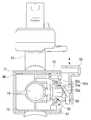
도 3 및 도 4에 도시한 바와 같이, 흡입노즐 조립체(30)는 노즐본체(31), 연결파이프(36), 및 피봇부(50)를 포함한다.3 and 4, the
노즐본체(31)는 상부 및 하부 케이싱(33, 34)으로 구성된다. 상부 및 하부 케이싱(33, 34)는 나사 등에 의해 서로 결합되어 있다. 상부 및 하부 케이싱(33, 34) 내에는 드럼브러시(35) 하측에서 하부 케이싱(34)에 형성된 공기흡입구(도시하지 않음)와 연결된 공기유로(도시하지 않음)가 형성되어 있다. 또, 노즐본체(31)의 상부 및 하부 케이싱(33, 34) 내에는 드럼브러시(35)를 구동하는 구동모터(37)가 지지브라켓에 설치된다. 구동모터(37)는 타이밍벨트(38)를 통해 드럼브러시(35)의 일측에 형성된 피동치차(39)에 연결된다. 도 6a 내지 도 8에 도시한 바와 같이, 하부 케이싱(34)의 하측에는 청소시 흡입노즐 조립체(30)의 이동이 용이하도록 복수 개의 바퀴(41)가 설치된다.The
연결파이프(36)는 노즐본체(31)와 연장관(20) 사이를 연결하는 것으로, 노즐본체(31)와 연장관(20) 사이에서 노즐본체(31)에 배치된다. 연결파이프(36)는 본 발명에 따라 피봇부(50)에 의해 적어도 두 개의 지점에서 피봇할 수 있게 연결되도록 제1 및 제2부분(43, 44)으로 분리된다.The connecting
피봇부(50)는 연결파이프(36)를 적어도 두 개의 지점, 예를들면, 노즐본체(31)와 연결파이프(36)의 제1부분(43) 사이, 및 연결파이프(36)의 제1 및 제2부분(43, 44) 사이에서 피봇할 수 있게 연결한다. The pivoting
이를 위해, 피봇부(50)는 제1피봇(55), 및 제2피봇(60)을 구비한다.To this end, the
제1피봇(55)은 연결파이프(36)의 제1부분(43)을 노즐본체(31)에 대해 약 0 도에서 90 도 사이의 각도범위 내에서 피봇할 수 있게 연결한다. 제1피봇(55)은 제1원통부(56)와 지지부(59)로 이루어진다. 제1원통부(56)는 일측은 연결파이프(36)의 제1부분(43)과 직각으로 제1부분(43)의 일단부와 연통하게 연결되고, 타측에는 흡입개구(58)가 형성된다. 또, 제1원통부(56)의 양측 중앙에는 회전축(57)이 돌출 형성되어 있다. 지지부(59)는 제1 및 제2격벽(62, 63)과 제3 및 제4격벽(도시하지 않음)을 구비한다. 제1 및 제2격벽(62, 63)은 노즐본체(31)의 하부 케이싱(34)의 후방 중앙에 일정간격을 두고 형성되고, 제3 및 제4격벽은 상부 케이싱(33)의 후방 중앙에서 제1 및 제2격벽(62, 63)과 대응하는 위치에 일정간격을 두고 형성된다. 따라서, 상부 및 하부 케이싱(33, 34)이 서로 겹합할 때, 제1 내지 제4격벽(62, 63)은 제1원통부(56)를 수용함과 함께 흡입개구(58)를 노즐본체(31)의 공기유로와 연통시키는 공간을 형성한다. 또한, 제1 내지 제4격벽(62, 63)의 각각의 상부 중앙에는 상부 및 하부 케이싱(33, 34)이 서로 겹합할 때 제1원통부(56)의 회전축(57)을 회전할 수 있게 지지하기 위한 원형 지지홀을 형성하는 반원형 지지홈(64)이 형성되어 있다.The
연결파이프(36)의 제1부분(43)이 노즐본체(31)에 대해 0 도에서 90 도의 각 도범위 밖으로 피봇하는 것을 방지하기 위해, 지지부(59)는 제1피봇제한부(65)를 구비한다. 제1피봇제한부(65)는 제1반원형 요홈(66)과 제2반원형 요홈(67)로 이루어 진다. 제1반원형 요홈(66)은 노즐본체(31)의 하부 케이싱(34)에서 지지부(59)의 제1 및 제2격벽(62, 63) 사이에 형성되고, 연결파이프(36)의 제1부분(43)의 일단부가 0 도에서 90 도의 각도범위의 하한각도, 즉, 약 0 도(대략 수평위치)에 위치할 때(도 3, 도 6b 및 도 7b 참조) 제1부분(43)의 일단부와 접촉하여 제1부분(43)의 회전을 제한한다. 제2반원형 요홈(67)은 노즐본체(31)의 상부 케이싱(33)에서 지지부(59)의 제3 및 제4격벽 사이에 형성되고, 제1부분(43)의 일단부가 0 도에서 90도의 각도범위의 상한각도, 즉, 약 90 도(대략 수직위치)에 위치할 때 제1부분(43)의 일단부와 접촉하여 제1부분(43)의 회전을 제한한다.To prevent the
선택적으로, 연결파이프(36)의 제1부분(43)을 수직위치와 수평위치에 록킹하기 위해, 제1피봇(55)은 제1록킹부(68)를 더 포함할 수 있다. 제1록킹부(68)는 제1원통부(56)의 일측의 원주면에 90 도의 간격을 두고 미소하게 돌출 형성된 제1 및 제2록킹돌기(71, 72), 및 하부 케이싱(34)에서 지지부(59)의 제1격벽(62)과 제1반원형 요홈(66) 사이에 형성된 제1 탄성록킹홈(73)으로 구성될 수 있다. 연결파이프(36)의 제1부분(43)은 수직위치에 있을 때는 제1록킹돌기(71)가 제1 탄성록킹홈(73)에 삽입되어 수직위치로 록킹되고, 수평위치에 있을 때는 제2록킹돌기(72)가 제1 탄성록킹홈(73)에 삽입되어 수평위치로 록킹된다. 제1록킹돌기(71) 또는 제2록킹돌기(72)와 제1 탄성록킹홈(73) 사이의 록킹력은 진공청소기를 캐니스터 형태로 사용시 사용자가 연장관(2)을 제1피봇(55)을 중심으로 회전시키는 힘에 의해 쉽게 해제될 수 있도록 설정된다. 이러한 제1록킹부(68)는 사용빈도가 많지 않으므로, 설계에 따라 생략될 수 있다.Optionally, the
제2피봇(60)은 연결파이프(36)의 제2부분(44)을 제1부분(43)에 대해 약 0 도에서 90 도의 각도범위 내에서 피봇할 수 있게 연결한다. 제2피봇(60)은 제2원통부(75)와 원통형 지지부(80)로 이루어 진다. 제2원통부(75)는 일측은 연결파이프(36)의 제1부분(43)에 직각으로 제1부분(43)의 타단부와 연통하게 연결되고, 타측에서는 배출개구(74; 5 참조)가 형성된다. 원통형 지지부(80)는 제2원통부(75)를 수용하여 회전할 수 있게 지지하고, 제2원통부(75)의 배출개구(74)를 제2부분(44)과 연통시키도록 제2부분(44)에 직각으로 제2부분(44)의 일단부와 연통하게 연결된다. 원통형 지지부(80)는 좌측 및 우측 케이싱(76, 77)내에 배치되고, 좌측 및 우측 케이싱(76, 77)에 의해 밀폐된다.The
연결파이프(36)의 제2부분(44)이 제1부분(43)에 대해 0 도에서 90 도의 각도범위 밖으로 피봇하는 것을 방지하기 위해, 원통형 지지부(80)는 제2피봇제한부(78)를 포함한다. 도 4에 도시한 바와 같이, 제2피봇제한부(78)는 원통형 지지부(80)에 원주방향으로 형성된 제1 및 제2 반원형 홈(79a, 79b)을 구비하는 개구(79)로 이루어진다. 제1반원형 홈(79a)은 제2부분(44)이 0 도에서 90 도의 각도범위의 상한각도, 즉 약 90 도(제1단부(43)와 대략 직각인 직각위치)에 위치할 때(도 3 및 도 6b 참조) 제1부분(43)의 타단부와 접촉하여 제2부분(44)의 피봇을 제한한다. 제2반원형 홈(79b)는 제2부분(44)이 0 도에서 90 도의 각도범위의 하한각도, 즉 0 도(제1단부(43)와 대략 평행인 평행위치)에 위치할 때(도 8 참조) 제1부 분(43)의 타단부와 접촉하여 제2부분(44)의 피봇을 제한한다.The
연결파이프(36)의 제2부분(44)을 제1부분(42)에 대해 약 0 도(제1단부(43)와 대략 평행인 평행위치) 또는 약 90 도(제1단부(43)와 대략 직각인 직각위치)에 록킹하기 위해, 제2피봇(60)은 제2록킹부(88)를 더 포함한다.The
제2록킹부(88)는 누르거나 터치할 때 연결파이프(36)의 제2부분(44)의 록킹을 해제하도록 할 수 있다. 이를 위해, 제2록킹부(88)는 이동부재(89), 고정부재(91), 및 레버(92)로 이루어진다. 도 5에 도시한 바와 같이, 이동부재(89)는 제2원통부(75)의 일측에 형성된 이동홈(75a)내에서 좌우로 이동할 수 있게 스프링에 의해 탄성적으로 지지된다. 이동부재(89)의 일측 중앙에는 경사 슬라이딩면(93a)을 구비한 가이드돌기(93)가 돌출 형성되고, 이동부재(89)의 일측의 가이드돌기(93) 둘레에는 적어도 하나의 제2록킹돌기(89a)가 돌출 형성된다. 고정부재(91)는 제2원통부(75)의 일측과 대향하게 원통형 지지부(80)에 고정되고, 제2록킹돌기(89a)를 수용하여 록킹하는 적어도 하나의 제2록킹홈(91a)이 제2록킹돌기(89a)에 대향한 위치에 형성된다. 레버(92)는 고정부재(91)의 가이드슬롯(91b)에 수직방향으로 이동할 수 있게 스프링에 의해 탄성적으로 지지되고, 하부에 가이드돌기(93)의 슬라이딩면(89b)과 맞물리는 대응 경사 슬라이딩면(92a)이 형성된다.The
또한, 제2록킹부(88)는 연결파이프(36)의 제2부분(44)이 제1부분(43)과 평행하게 펴진 평행위치나(도 8 참조) 직각으로 벤딩된 직각위치에 있을 때(도 3 및 도 6b 참조), 제2부분(44)의 피봇을 록킹할 수 있다. 이를 위해, 이동부재(89)의 제2록킹돌기(89a)는 연결파이프(36)의 제2부분(44)의 평행위치 및 직각위치에 맞추어 원주상으로 90 도 각도로 배치된 4 개의 돌기로 구성되고, 고정부재(91)의 제2록킹홈(91a)은 4 개의 돌기에 대향하게 원주상으로 90 도 각도로 배치된 4 개의 홈으로 구성될 수 있다.The
따라서, 레버(92)가 사용자의 누름이나 터치에 의해 아래로 이동하면, 이동부재(89)는 경사 슬라이딩면(89b)이 레버(92)의 대응 경사 슬라이딩면(92a)에 의해 눌러져 이동홈(75a)을 따라 우측(도 4 및 도 5의 좌측)으로 이동하고, 이에 따라, 이동부재(89)의 제2록킹돌기(89a)는 고정부재(91)의 제2록킹홈(91a)으로부터 이격된다. 그 결과, 제2원통부(80)와 연결된 연결파이프(36)의 제2부분(44)은 제2원통부(75)와 연결된 연결파이프(36)의 제1부분(43)에 대해 자유롭게 피봇될 수 있다.When the
반대로, 도 5에 도시한 바와 같이, 레버(92)가 사용자의 누름 또는 터치 해제로 인해 스프링에 의해 위로 이동하면, 이동부재(89)는 스프링에 의해 이동홈(75a)을 따라 좌측(도 4 및 도 5의 우측)으로 이동하고, 이에 따라, 이동부재(89)의 제2록킹돌기(89a)는 고정부재(91)의 제2록킹홈(91a)에 삽입된다. 그 결과, 연결파이프(36)의 제2부분(44)은 제1부분(43)에 대한 피봇이 록킹된다. 그러나, 이때, 연결파이프(36)의 제2부분(44)이 평행위치 및 직각위치에 있지 않으면, 제2록킹돌기(89a)와 제2록킹홈(91a)이 연결파이프(36)의 제2부분(44)의 평행위치 및 직각위치에 맞추어 원주상으로 90 도 각도로 배치되어 있기 때문에, 제2록킹돌기(89a)와 제2록킹홈(91a)의 위치가 일치하지 않는다. 따라서, 제2록킹돌기(89a)는 고정부재(91)에 의해 제2록킹홈(91a)에 삽입되지 못한다. 이 경우, 연결파이프(36)의 제2부분(44)은 평행위치 및 직각위치에 위치할 때까지 제1부분(43)에 대해 자유 롭게 피봇될 수 있다.5, when the
이와 같이 구성된 피봇부(50)를 구비한 업라이트 및 캐니스터 겸용 진공청소기(1)는, 도 1 및 도 6a에 도시한 바와 같이 흡입호스(15)를 통해 연장관(20)에 연결된 청소기 본체(10)를 연결파이프(36)의 제1부분(43)과 제2피봇(60) 위쪽에 장착하여 보관된다. 이를 위해, 진공청소기(1)는 장착부(95)를 포함한다. 장착부(95)는 탑재돌기(96), 탑재홈(도시하지 않음), 및 지지요부(97)로 이루어진다. 탑재돌기(96)는 연결파이프(36)의 제2부분(44)의 타부분 상부에서 숫소켓(45) 근처에 형성된다. 탑재홈은 탑재돌기(96)를 수용하여 록킹하도록 탑재돌기(96)에 대향하게 청소기 본체(10)의 바닥면 하부에 형성된다. 지지요부(97)는 청소기 본체(10)의 후측면에 제2피봇(60)의 상측부와 대응하는 형상으로 형성된다. 지지요부(97)는 도 1 및 도 6a에 도시한 바와 같이 청소기 본체(10)가 업라이트 형태의 보관위치에 있을 때는 제2피봇(60)의 상측부에 안착 지지되고, 도 7a에 도시한 바와 같이 업라이트 형태의 사용위치에 있을 때는 제2피봇(60)의 상측부로부터 떨어질 수 있다. 이때, 청소기 본체(10)를 더 안정적으로 지지하기 위해, 연장관(20)과 대향하는 청소기 본체(10)의 바닥면에는 연장관(20)의 일부를 길이방향으로 수용 및 지지하는 장홈(98)이 더 형성될 수 있다.1 and 6A, the upright and
이와 같이, 본 발명에 따른 업라이트 및 캐니스터 겸용 진공청소기(1)는 청소기 본체(10)가 노즐본체(31) 대신, 연결파이프(36)의 제1부분(43)과 제1피봇(60) 위쪽에 장착되므로, 종래의 청소기와 같이 업라이트 형태로 사용시 청소기 본체(10)를 안정적으로 장착 유지하기 위해 노즐본체(31)의 크기, 특히, 전후 폭을 크게 형성할 필요가 없다. 예를들면, 도 8에 도시한 바와 같이, 노즐본체(31)의 전후 폭(L)은 L' 만큼 감소 될 수 있다. 따라서, 본 발명에 따른 업라이트 및 캐니스터 겸용 진공청소기(1)는 계단 등과 좁은 전후 폭을 갖는 피 청소면을 청소하는 캐니스터 형태로 사용할 경우에도, 노즐본체(31)가 계단의 폭 너머로 돌출되어 노즐본체(10)의 바닥면이 계단과 완전하게 접촉하지 않아 오물흡입 효율이 떨어지는 문제점이 방지된다. 또한, 사용자의 힘과 연장관(20)의 중량이 가해지는 제1피봇(55)이 노즐본체(31)와 함께 계단내에 위치하기 때문에, 사용자는 노즐본체(10)를 계단면에 대해 자유롭게 누르면서 이동시킬 수 있고, 이에 따라 청소작업이 쉽게 된다.As described above, the
이상에서, 본 발명에 따른 업라이트 및 캐니스터 겸용 진공청소기(1)는 제1 및 제2피봇(55, 60)이 원통부(56; 75)와 지지부(59; 80)로 구성된 것으로 예시 및 설명하였지만, 본 발명은 이것으로 한정되지 않는다. 즉, 도 9a 및 도 9b에 도시한 바와 같이, 제1 및 제2피봇중 하나, 예를들면, 제2피봇(60')은 연결파이프(36)의 제1 및 제2부분(43, 44)를 연결하는 플렉시블호스(61)를 포함할 수 있다. 이때, 플렉시블호스(61)는 플렉시블호스(61)를 감싸도록 연결파이프(36)의 제2부분(44)에 설치된 보호커버(80')에 의해 보호될 수 있다. 또, 제1 및 제2부분(43, 44) 사이의 피봇록킹은 연결파이프(36)의 제1부분(43)의 제1브라켓(75')과 보호커버(80')의 제2브라켓(85)의 양단부를 나선 연결하는 나선축(62)을 노브(69)로 회전시켜 죄우는 것에 의해 이루어 질 수 있다. 선택적으로, 제1 및 제2부분(43, 44) 사이의 피봇록킹은 제1브라켓(75')과 제2브라켓(85)의 양단부에서 양단부를 지지하는 피봇축(도시하지 않음) 둘레에 약 90도의 각도로 각각 형성된 복수 개의 록깅돌기(도시하지 않음)와 복수 개의 록킹홈(도시하지 않음)에 의해 이루어질 수 있다.The upright and
이하에서는 이상과 같이 구성된 본 발명에 따른 업라이트 및 캐니스터 겸용 진공청소기(1)를 업라이트 형태 및 캐니스터 형태로 사용하는 동작을 도 1 내지 도 8을 참조하여 상세히 설명하기로 한다.Hereinafter, the operation of using the upright and
먼저, 도 1 및 도 6a에 도시한 바와 같이, 진공청소기(1)가 업라이트 형태의 보관위치에 있을 때, 연결파이프(36)의 제1부분(43)은 제1피봇제한부(65)의 제1반원형 요홈(66)에 의해 청소면과 대략적으로 평행하게 위치되고, 제2부분(44)은 제2피봇(60)의 제2록킹부(88)에 의해 제1부분(43)에 대해 약 90 도의 각도를 갖는 직각위치에 위치한다(도 6b 참조). 또, 청소기 본체(1)은 장착부(95)에 의해 연결파이프(36)의 제1부분(43)과 피봇부(50)의 제2피봇(60) 위쪽에 장착되어 있다.First, as shown in Figs. 1 and 6A, when the
이러한 업라이트 형태의 보관위치에서 사용자가 진공청소기(1)를 사용하여 카펫, 마루 등과 같은 넓은 피청소면을 청소하고자 할 경우, 사용자가 제2록킹부(88)의 레버(92)를 발로 누르거나 손으로 터치하여 아래로 이동시키면, 도 4 및 도 5에 관하여 설명한 바와 같이, 이동부재(89)의 제2록킹돌기(89a)는 고정부재(91)의 제2록킹홈(91a)으로부터 해제되고, 그 결과, 연결파이프(36)의 제2부분(44)은 제1부분(43)에 대해 자유롭게 피봇될 수 있다. 이 상태에서, 도 7a 및 도 7b에 도시한 바와 같이, 사용자는 연장관(20)의 조작핸들(21)을 사용하여 제1 및 제2부분(43, 44)이 서로 평행하거나 직각이 되지 않은 범위내에서 연장관(20)을 제2피봇(60)을 중심으로 피봇시키면서 노즐본체(31)를 피 청소면에 밀착시켜 청소를 수행한다.When the user wants to clean a wide surface to be cleaned such as a carpet, floor or the like using the
청소가 완료된 후, 진공청소기(1)를 다시 보관위치로 보관하고자 할 경우, 사용자는 조작핸들(21)을 사용하여 제1 및 제2부분(43, 44)이 서로 직각이 되도록 연장관(20)을 제2피봇(60)을 중심으로 피봇시키면, 제2록킹부(88)는 도 5에 관하여 설명한 바와 같이, 제2록킹돌기(89a)가 제2록킹홈(91a)에 삽입되어 연결파이프(36)의 제2부분(44)의 제1부분(43)에 대한 피봇을 록킹한다. 그 결과, 진공청소기(1)는 도 1 및 도 6a에 도시한 바와 같이 보관위치로 복귀된다.When the
다음으로, 계단과 같은 좁은 폭을 갖는 피 청소면을 청소하기 위해, 도 1 및 도 6a에 도시한 바와 같이 업라이트 형태의 보관위치로 유지된 진공청소기(1)를 캐니스터 형태로 사용하고자 한다면, 사용자는 본체 손잡이(11)를 사용하여 청소기 본체(10)를 흡입노즐 조립체(30) 및 연장관(20)으로부터 분리한 후, 도 2에 도시한 바와 같이, 앞뒤 바퀴(13a, 13b)가 피 청소면의 바닥에 닿도록 피 청소면위로 이동시킨다. 그 다음, 사용자가 제2록킹부(88)의 레버(92)를 발로 누르거나 손으로 터치하여 아래로 이동시키면, 위에서 설명한 바와 같이, 제2록킹돌기(89a)는 제2록킹홈(91a)으로부터 해제되어, 연결파이프(36)의 제2부분(44)은 제1부분(43)에 대해 자유롭게 피봇될 수 있다. 이 상태에서, 사용자는 조작핸들(21)을 사용하여 제1 및 제2부분(43, 44)이 서로 대략 수직인 직각위치(도 6b 참조)에서부터 서로 대략 평행한 평행위치(도 2 및 도 8 참조)가 되도록 연장관(20)을 제2피봇(60)을 중심으로 피봇시키면, 제2록킹부(88)는 위에서 설명한 바와 같이, 제2록킹돌기(89a)가 제2록킹홈(91a)에 삽입되어 연결파이프(36)의 제2부분(44)의 제1부분(43)에 대한 피봇을 록킹한다. 그 결과, 진공청소기(1)는 도 2 및 도 8에 도시한 바와 같이, 연결파이 프(36)의 제2부분(44)은 제1부분(43)과 대략적으로 평행하게 고정되고 제1부분(43)은 제1피봇(55)을 중심으로 약 0 도에서 90 도 사이의 각도범위내에서 피봇될 수 있다. 이 상태에서, 사용자는 조작핸들(21)을 사용하여 연장관(20)을 제1피봇(55)을 중심으로 피봇시키면서 노즐본체(31)를 피 청소면에 밀착시켜 청소를 수행한다.Next, if it is desired to use the
청소가 완료된 후, 진공청소기(1)를 다시 보관위치에 보관하고자 할 경우, 사용자는 진공청소기(1)를 위에서 설명한 업라이트 형태의 보관위치에서부터 캐니스터 형태로 변환하는 동작의 역순으로 조작한다.When the
즉, 사용자는 제2록킹부(88)의 레버(92)를 발로 누르거나 손으로 터치하여 아래로 이동시켜 연결파이프(36)의 제2부분(44)을 제1부분(43)에 대해 자유롭게 피봇될 수 있게 한다. 그 다음, 사용자는 조작핸들(21)을 사용하여 제1 및 제2부분(43, 44)이 서로 대략 평행한 평행위치(도 2 및 도 8 참조)에서부터 대략 90 도의 각도를 갖는 직각위치(도 6b 참조)가 되도록 연장관(20)을 제2피봇(60)을 중심으로 피봇시킴과 함께, 도 6b에 도시한 바와 같이, 제1부분(43)이 제1피봇제한부(65)의 제1반원형 요홈(66)에 의해 피 청소면과 대략적으로 평행하게 위치되게 한다. 이 상태에서, 사용자는 본체 손잡이(11)를 사용하여 청소기 본체(10)를 흡입노즐 조립체(30) 위쪽으로 이동시킨 다음, 장착부(95)를 통해 연결파이프(36)의 제1부분(43)과 피봇부(50)의 제2피봇(55) 위에 장착한다. 그 결과, 진공청소기(1)는 도 1 및 도 6a에 도시한 바와 같이 보관위치로 복귀된다.That is, the user can press the
이상에서, 본 발명을 본 발명의 원리를 예시하기 위한 바람직한 실시예에 대하여 도시하고 설명하였으나, 본 발명은 그와 같이 도시되고 설명된 그대로의 구성 및 작용으로 한정되는 것이 아니다. 오히려, 첨부된 특허청구범위의 사상 및 범주를 일탈함이 없이 본 발명에 대한 변경 및 수정이 가능함을 당업자들은 잘 이해할 수 있을 것이다. 따라서, 그러한 모든 적절한 변경 및 수정과 균등물들도 본 발명의 범위에 속하는 것으로 간주되어야 할 것이다.While the present invention has been particularly shown and described with reference to exemplary embodiments thereof, it is to be understood that the invention is not limited to the disclosed exemplary embodiments. It will be appreciated by those skilled in the art that changes and modifications may be made thereto without departing from the spirit and scope of the appended claims. Accordingly, all such appropriate modifications and changes, and equivalents thereof, should be regarded as within the scope of the present invention.
도 1은 본 발명의 일 실시예에 따른 업라이트 및 캐니스터 겸용 진공청소기를 업라이트 형태의 보관위치로 보관된 것을 예시하는 개략 사시도,BRIEF DESCRIPTION OF THE DRAWINGS FIG. 1 is a schematic perspective view illustrating a case where a vacuum cleaner for both an upright and a canister according to an embodiment of the present invention is stored in an upright-
도 2는 도 1에 도시한 진공청소기를 캐니스터 형태로 사용하는 것을 예시하는 개략 사시도,FIG. 2 is a schematic perspective view illustrating the use of the vacuum cleaner shown in FIG. 1 in the form of a canister;
도 3는 도 1에 도시된 진공청소기의 흡입노즐 조립체를 예시하는 사시도,FIG. 3 is a perspective view illustrating the suction nozzle assembly of the vacuum cleaner shown in FIG. 1,
도 4는 도 3에 도시한 흡입노즐 조립체의 분해 사시도,FIG. 4 is an exploded perspective view of the suction nozzle assembly shown in FIG. 3,
도 5는 도 3에 선 V-V를 따라 도시한 단면도,5 is a cross-sectional view taken along the line V-V in Fig. 3,
도 6a는 도 1에 도시한 진공청소기의 측면도,FIG. 6A is a side view of the vacuum cleaner shown in FIG. 1,
도 6b는 도 6a에 도시한 진공청소기에서 청소기 본체를 제거한 상태로 도시한 부분 측면도,FIG. 6B is a partial side view of the vacuum cleaner shown in FIG. 6A,
도 7a는 도 1에 도시한 진공청소기를 업라이트 형태로 사용하는 것을 예시하는 측면도,FIG. 7A is a side view illustrating the use of the vacuum cleaner shown in FIG. 1 in the form of an upright,
도 7b는 도 7a에 도시한 진공청소기에서 청소기 본체를 제거한 상태로 도시한 부분 측면도,FIG. 7B is a partial side view of the vacuum cleaner shown in FIG. 7A with the cleaner main body removed. FIG.
도 8은 도 2에 도시한 진공청소기의 흡입노즐 조립체의 부분 측면도, 및8 is a partial side view of the suction nozzle assembly of the vacuum cleaner shown in Fig. 2, and Fig.
도 9a 및 도 9b는 본 발명의 다른 실시예에 따른 업라이트 및 캐니스터 겸용 진공청소기를 청소기 본체가 제거한 상태에서 업라이트 형태로 사용하는 것을 예시하는 부분 사시도이다.9A and 9B are partial perspective views illustrating use of an upright and a canister vacuum cleaner according to another embodiment of the present invention in an upright state with the cleaner main body removed.
*도면 내 주요부분에 대한 부호설명** Explanation of key parts in the drawing *
1: 진공청소기10: 청소기 본체1: Vacuum cleaner 10: Cleaner body
20: 연장관330: 흡입노즐 조립체20: extension tube 3 30: suction nozzle assembly
31: 노즐본체36: 연결파이프31: nozzle body 36: connecting pipe
50: 피봇부55: 제1피봇50: pivot portion 55: first pivot
56: 제1원통부59: 지지부56: first cylindrical portion 59:
60, 60': 제2피봇61: 플렉시블호스60, 60 ': second pivot 61: flexible hose
65: 제1피봇제한부68: 제1록킹부65: first pivot restricting portion 68: first locking portion
75: 제2원통부80: 원통형 지지부75: second cylindrical portion 80: cylindrical supporting portion
78: 제2피봇제한부88: 제2록킹부78: second pivot restricting portion 88: second locking portion
89: 이동부재91: 고정부재89: moving member 91: fixing member
92: 레버95: 장착부92: lever 95:
96: 탑재돌기98: 장홈96: mounting projection 98: groove
Claims (23)
Translated fromKoreanPriority Applications (3)
| Application Number | Priority Date | Filing Date | Title |
|---|---|---|---|
| KR1020080124891AKR101534063B1 (en) | 2008-12-09 | 2008-12-09 | Vacuum cleaner for both upright and canister |
| US12/584,326US8468646B2 (en) | 2008-12-09 | 2009-09-03 | Vacuum cleaner for using in both upright form and canister form |
| GB0917561AGB2466100B (en) | 2008-12-09 | 2009-10-07 | Vacuum cleaner for using in both upright form and canister form |
Applications Claiming Priority (1)
| Application Number | Priority Date | Filing Date | Title |
|---|---|---|---|
| KR1020080124891AKR101534063B1 (en) | 2008-12-09 | 2008-12-09 | Vacuum cleaner for both upright and canister |
Publications (2)
| Publication Number | Publication Date |
|---|---|
| KR20100066200A KR20100066200A (en) | 2010-06-17 |
| KR101534063B1true KR101534063B1 (en) | 2015-07-07 |
Family
ID=41402671
Family Applications (1)
| Application Number | Title | Priority Date | Filing Date |
|---|---|---|---|
| KR1020080124891AExpired - Fee RelatedKR101534063B1 (en) | 2008-12-09 | 2008-12-09 | Vacuum cleaner for both upright and canister |
Country Status (3)
| Country | Link |
|---|---|
| US (1) | US8468646B2 (en) |
| KR (1) | KR101534063B1 (en) |
| GB (1) | GB2466100B (en) |
Families Citing this family (63)
| Publication number | Priority date | Publication date | Assignee | Title |
|---|---|---|---|---|
| US10765277B2 (en) | 2006-12-12 | 2020-09-08 | Omachron Intellectual Property Inc. | Configuration of a surface cleaning apparatus |
| CN101626715B (en) | 2006-12-12 | 2012-07-25 | Gbd公司 | Convertible surface cleaning apparatus |
| US12220099B2 (en) | 2006-12-12 | 2025-02-11 | Omachron Intellectual Property Inc. | Surface cleaning apparatus |
| US8950039B2 (en) | 2009-03-11 | 2015-02-10 | G.B.D. Corp. | Configuration of a surface cleaning apparatus |
| US11751733B2 (en) | 2007-08-29 | 2023-09-12 | Omachron Intellectual Property Inc. | Portable surface cleaning apparatus |
| US12048409B2 (en) | 2007-03-11 | 2024-07-30 | Omachron Intellectual Property Inc. | Portable surface cleaning apparatus |
| US9211044B2 (en) | 2011-03-04 | 2015-12-15 | Omachron Intellectual Property Inc. | Compact surface cleaning apparatus |
| CA2674376A1 (en) | 2009-03-13 | 2010-09-13 | G.B.D. Corp. | Surface cleaning apparatus with different cleaning configurations |
| US9427122B2 (en) | 2009-03-13 | 2016-08-30 | Omachron Intellectual Property Inc. | Surface cleaning apparatus |
| US11690489B2 (en) | 2009-03-13 | 2023-07-04 | Omachron Intellectual Property Inc. | Surface cleaning apparatus with an external dirt chamber |
| US9198551B2 (en)* | 2013-02-28 | 2015-12-01 | Omachron Intellectual Property Inc. | Surface cleaning apparatus |
| US11612288B2 (en) | 2009-03-13 | 2023-03-28 | Omachron Intellectual Property Inc. | Surface cleaning apparatus |
| US9480373B2 (en) | 2009-03-13 | 2016-11-01 | Omachron Intellectual Property Inc. | Surface cleaning apparatus |
| US9591953B2 (en) | 2009-03-13 | 2017-03-14 | Omachron Intellectual Property Inc. | Surface cleaning apparatus |
| CA2674761C (en) | 2009-03-13 | 2016-10-04 | G.B.D. Corp. | Surface cleaning apparatus with different cleaning configurations |
| US9226633B2 (en) | 2009-03-13 | 2016-01-05 | Omachron Intellectual Property Inc. | Surface cleaning apparatus |
| CA2967272C (en) | 2009-03-13 | 2018-01-02 | Omachron Intellectual Property Inc. | Hand vacuum cleaner |
| US9392916B2 (en) | 2009-03-13 | 2016-07-19 | Omachron Intellectual Property Inc. | Surface cleaning apparatus |
| US9138114B2 (en) | 2009-03-13 | 2015-09-22 | Omachron Intellectual Property Inc. | Surface cleaning apparatus |
| GB2469049B (en)* | 2009-03-31 | 2013-04-17 | Dyson Technology Ltd | A cleaning appliance with steering mechanism |
| CA2674758C (en)* | 2009-07-30 | 2017-02-21 | G.B.D. Corp. | Surface cleaning apparatus |
| GB2474464B (en)* | 2009-10-15 | 2013-11-20 | Dyson Technology Ltd | A surface treating appliance |
| GB2474466B (en)* | 2009-10-15 | 2014-03-05 | Dyson Technology Ltd | A surface treating appliance |
| GB2474472B (en)* | 2009-10-15 | 2013-10-23 | Dyson Technology Ltd | A surface treating appliance |
| GB2474465B (en)* | 2009-10-15 | 2013-10-23 | Dyson Technology Ltd | A surface treating appliance |
| GB2474473B (en)* | 2009-10-15 | 2013-10-23 | Dyson Technology Ltd | A surface treating appliance |
| GB0918027D0 (en)* | 2009-10-15 | 2009-12-02 | Dyson Technology Ltd | A surface trating appliance |
| GB2474462B (en)* | 2009-10-15 | 2013-12-11 | Dyson Technology Ltd | A surface treating appliance with domed-shaped wheels |
| GB2474475B (en)* | 2009-10-15 | 2013-10-23 | Dyson Technology Ltd | A surface treating appliance |
| GB2474463B (en)* | 2009-10-15 | 2013-11-13 | Dyson Technology Ltd | A surface treating appliance |
| GB2474469B (en)* | 2009-10-15 | 2013-11-13 | Dyson Technology Ltd | A surface treating appliance |
| GB2474470B (en) | 2009-10-15 | 2013-10-23 | Dyson Technology Ltd | A surface treating appliance |
| US8875340B2 (en)* | 2010-03-12 | 2014-11-04 | G.B.D. Corp. | Surface cleaning apparatus with enhanced operability |
| US8887352B2 (en)* | 2011-02-25 | 2014-11-18 | Panasonic Corporation Of North America | Canister vacuum cleaner incorporating a control handle and nozzle assembly with upright swivel lock |
| US20120246866A1 (en)* | 2011-03-28 | 2012-10-04 | Emerson Electric Co. | Support System Adjustable by Like Motion and Method of Use |
| US20140331445A1 (en)* | 2011-12-14 | 2014-11-13 | Euro-Pro Operating Llc | Surface cleaning apparatus with a sideways pivoting handle |
| US10016107B2 (en) | 2011-12-14 | 2018-07-10 | Sharkninja Operating Llc | Surface cleaning apparatus with a sideways pivoting handle |
| US20140041149A1 (en)* | 2012-08-09 | 2014-02-13 | Techtronic Floor Care Technology Limited | Vacuum cleaner including a removable canister assembly |
| US9364127B2 (en) | 2013-02-28 | 2016-06-14 | Omachron Intellectual Property Inc. | Surface cleaning apparatus |
| US9314138B2 (en) | 2013-02-28 | 2016-04-19 | Omachron Intellectual Property Inc. | Surface cleaning apparatus |
| US9215960B2 (en) | 2013-02-28 | 2015-12-22 | Omachron Intellectual Property Inc. | Surface cleaning apparatus |
| US9456721B2 (en) | 2013-02-28 | 2016-10-04 | Omachron Intellectual Property Inc. | Surface cleaning apparatus |
| US8943647B1 (en) | 2013-08-09 | 2015-02-03 | Techtronic Floor Care Technology Limited | Vacuum cleaner including a removable handle assembly |
| CN105979839B (en) | 2014-01-17 | 2019-08-30 | 创科地板护理技术有限公司 | Vacuum cleaner with detachable filter tank component |
| AU2015268068B2 (en)* | 2014-05-29 | 2018-05-10 | Omachron Intellectual Property Inc. | Surface cleaning apparatus |
| US9414725B2 (en) | 2014-12-05 | 2016-08-16 | Panasonic Corporation Of North America | Upright vacuum cleaner with two auxiliary operating modes |
| US10080471B2 (en) | 2015-12-21 | 2018-09-25 | Electrolux Home Care Products, Inc. | Versatile vacuum cleaners |
| US11478117B2 (en) | 2016-08-29 | 2022-10-25 | Omachron Intellectual Property Inc. | Surface cleaning apparatus |
| US9962050B2 (en) | 2016-08-29 | 2018-05-08 | Omachron Intellectual Property Inc. | Surface cleaning apparatus |
| US10136780B2 (en) | 2016-08-29 | 2018-11-27 | Omachron Intellectual Property Inc. | Surface cleaning apparatus |
| US10433689B2 (en) | 2016-08-29 | 2019-10-08 | Omachron Intellectual Property Inc. | Surface cleaning apparatus |
| US10441124B2 (en) | 2016-08-29 | 2019-10-15 | Omachron Intellectual Property Inc. | Surface cleaning apparatus |
| US10292550B2 (en) | 2016-08-29 | 2019-05-21 | Omachron Intellectual Property Inc. | Surface cleaning apparatus |
| US10413141B2 (en) | 2016-08-29 | 2019-09-17 | Omachron Intellectual Property Inc. | Surface cleaning apparatus |
| US10405711B2 (en) | 2016-08-29 | 2019-09-10 | Omachron Intellectual Property Inc. | Surface cleaning apparatus |
| US10441125B2 (en) | 2016-08-29 | 2019-10-15 | Omachron Intellectual Property Inc. | Surface cleaning apparatus |
| US10321794B2 (en) | 2016-08-29 | 2019-06-18 | Omachron Intellectual Property Inc. | Surface cleaning apparatus |
| US10729295B2 (en) | 2016-08-29 | 2020-08-04 | Omachron Intellectual Property Inc. | Surface cleaning apparatus |
| US10136779B2 (en) | 2016-08-29 | 2018-11-27 | Omachron Intellectual Property Inc. | Surface cleaning apparatus |
| US11285495B2 (en) | 2016-12-27 | 2022-03-29 | Omachron Intellectual Property Inc. | Multistage cyclone and surface cleaning apparatus having same |
| KR20220012727A (en)* | 2020-07-23 | 2022-02-04 | 엘지전자 주식회사 | Vacuum Cleaner |
| KR20220012730A (en) | 2020-07-23 | 2022-02-04 | 엘지전자 주식회사 | Vacuum Cleaner |
| FR3129280B1 (en)* | 2021-11-25 | 2023-10-27 | Seb Sa | Vacuum cleaner equipped with a suction head that can be moved between retracted and extended positions |
Citations (2)
| Publication number | Priority date | Publication date | Assignee | Title |
|---|---|---|---|---|
| KR20010093070A (en)* | 2000-03-23 | 2001-10-27 | 마찌다 가쯔히꼬 | Electric vacuum cleaner |
| JP3868953B2 (en)* | 2003-12-22 | 2007-01-17 | 株式会社日立製作所 | Electric vacuum cleaner |
Family Cites Families (7)
| Publication number | Priority date | Publication date | Assignee | Title |
|---|---|---|---|---|
| EP0653640B1 (en) | 1993-11-16 | 2000-01-19 | Wako Pure Chemical Industries Ltd | Process for separating and measuring glycoprotein |
| JP3504744B2 (en) | 1994-01-20 | 2004-03-08 | 株式会社大宇エレクトロニクス | Dual type vacuum cleaner |
| JP3609582B2 (en)* | 1997-06-23 | 2005-01-12 | 三洋電機株式会社 | Electric vacuum cleaner |
| JPH1189757A (en) | 1997-09-18 | 1999-04-06 | Sanyo Electric Co Ltd | Electric vacuum cleaner |
| GB2402047B (en) | 2003-05-29 | 2006-07-19 | Dyson Ltd | A cleaning head |
| KR101491002B1 (en) | 2007-12-05 | 2015-02-06 | 삼성전자주식회사 | Vacuum cleaner |
| KR20100006786A (en) | 2008-07-10 | 2010-01-21 | 삼성전자주식회사 | Upright type cleaner |
- 2008
- 2008-12-09KRKR1020080124891Apatent/KR101534063B1/ennot_activeExpired - Fee Related
- 2009
- 2009-09-03USUS12/584,326patent/US8468646B2/ennot_activeExpired - Fee Related
- 2009-10-07GBGB0917561Apatent/GB2466100B/ennot_activeExpired - Fee Related
Patent Citations (2)
| Publication number | Priority date | Publication date | Assignee | Title |
|---|---|---|---|---|
| KR20010093070A (en)* | 2000-03-23 | 2001-10-27 | 마찌다 가쯔히꼬 | Electric vacuum cleaner |
| JP3868953B2 (en)* | 2003-12-22 | 2007-01-17 | 株式会社日立製作所 | Electric vacuum cleaner |
Also Published As
| Publication number | Publication date |
|---|---|
| KR20100066200A (en) | 2010-06-17 |
| GB2466100A (en) | 2010-06-16 |
| GB0917561D0 (en) | 2009-11-25 |
| US8468646B2 (en) | 2013-06-25 |
| GB2466100B (en) | 2010-11-03 |
| US20100139030A1 (en) | 2010-06-10 |
Similar Documents
| Publication | Publication Date | Title |
|---|---|---|
| KR101534063B1 (en) | Vacuum cleaner for both upright and canister | |
| CA2647384C (en) | Electric vacuum cleaner, and vacuum cleaner hose | |
| EP1994868B1 (en) | Nozzle assembly for a vacuum cleaner | |
| US7681279B2 (en) | Vacuum cleaner | |
| JPWO2018087937A1 (en) | Extension tube of vacuum cleaner | |
| US20090044371A1 (en) | Vacuum cleaner for use in both upright form and canister form | |
| WO2013121702A1 (en) | Suction device for electric vacuum cleaner, and electric vacuum cleaner with same | |
| JP2009504305A (en) | Angle adjustment device for upright vacuum cleaner | |
| US20050273972A1 (en) | Extension pipe supporting apparatus and a vacuum cleaner having the same | |
| JP5901331B2 (en) | Electric vacuum cleaner | |
| JP4946727B2 (en) | Suction tool and electric vacuum cleaner used therefor | |
| JP4417758B2 (en) | Vacuum cleaner | |
| JP2006198152A (en) | Electric vacuum cleaner | |
| KR20010038842A (en) | Suction nozzle unit for vacuum cleaner | |
| JP4228227B2 (en) | Electric vacuum cleaner | |
| JP4734434B2 (en) | Vacuum cleaner | |
| JP2005245897A (en) | Electric vacuum cleaner | |
| KR200369897Y1 (en) | Vacuum cleaner | |
| CN1190568A (en) | Electric Sweeper | |
| JP4930264B2 (en) | Suction tool and electric vacuum cleaner using the same | |
| JPS6347449B2 (en) | ||
| JP2001346739A (en) | Vacuum cleaner suction device and vacuum cleaner | |
| JPH10323302A (en) | Upright-type vacuum cleaner | |
| JPH06245879A (en) | Vacuum cleaner | |
| JPH04371124A (en) | upright vacuum cleaner |
Legal Events
| Date | Code | Title | Description |
|---|---|---|---|
| PA0109 | Patent application | St.27 status event code:A-0-1-A10-A12-nap-PA0109 | |
| PG1501 | Laying open of application | St.27 status event code:A-1-1-Q10-Q12-nap-PG1501 | |
| N231 | Notification of change of applicant | ||
| PN2301 | Change of applicant | St.27 status event code:A-3-3-R10-R13-asn-PN2301 St.27 status event code:A-3-3-R10-R11-asn-PN2301 | |
| R18-X000 | Changes to party contact information recorded | St.27 status event code:A-3-3-R10-R18-oth-X000 | |
| A201 | Request for examination | ||
| PA0201 | Request for examination | St.27 status event code:A-1-2-D10-D11-exm-PA0201 | |
| D13-X000 | Search requested | St.27 status event code:A-1-2-D10-D13-srh-X000 | |
| D14-X000 | Search report completed | St.27 status event code:A-1-2-D10-D14-srh-X000 | |
| E902 | Notification of reason for refusal | ||
| PE0902 | Notice of grounds for rejection | St.27 status event code:A-1-2-D10-D21-exm-PE0902 | |
| E13-X000 | Pre-grant limitation requested | St.27 status event code:A-2-3-E10-E13-lim-X000 | |
| P11-X000 | Amendment of application requested | St.27 status event code:A-2-2-P10-P11-nap-X000 | |
| P13-X000 | Application amended | St.27 status event code:A-2-2-P10-P13-nap-X000 | |
| E701 | Decision to grant or registration of patent right | ||
| PE0701 | Decision of registration | St.27 status event code:A-1-2-D10-D22-exm-PE0701 | |
| PR0701 | Registration of establishment | St.27 status event code:A-2-4-F10-F11-exm-PR0701 | |
| PR1002 | Payment of registration fee | St.27 status event code:A-2-2-U10-U11-oth-PR1002 Fee payment year number:1 | |
| PG1601 | Publication of registration | St.27 status event code:A-4-4-Q10-Q13-nap-PG1601 | |
| FPAY | Annual fee payment | Payment date:20180530 Year of fee payment:4 | |
| PR1001 | Payment of annual fee | St.27 status event code:A-4-4-U10-U11-oth-PR1001 Fee payment year number:4 | |
| PC1903 | Unpaid annual fee | St.27 status event code:A-4-4-U10-U13-oth-PC1903 Not in force date:20190701 Payment event data comment text:Termination Category : DEFAULT_OF_REGISTRATION_FEE | |
| PC1903 | Unpaid annual fee | St.27 status event code:N-4-6-H10-H13-oth-PC1903 Ip right cessation event data comment text:Termination Category : DEFAULT_OF_REGISTRATION_FEE Not in force date:20190701 |