KR101531829B1 - Phacoemulsification hand piece with integrated aspiration pump - Google Patents
Phacoemulsification hand piece with integrated aspiration pumpDownload PDFInfo
- Publication number
- KR101531829B1 KR101531829B1KR1020127017536AKR20127017536AKR101531829B1KR 101531829 B1KR101531829 B1KR 101531829B1KR 1020127017536 AKR1020127017536 AKR 1020127017536AKR 20127017536 AKR20127017536 AKR 20127017536AKR 101531829 B1KR101531829 B1KR 101531829B1
- Authority
- KR
- South Korea
- Prior art keywords
- needle
- suction pump
- suction
- eye
- handpiece
- Prior art date
- Legal status (The legal status is an assumption and is not a legal conclusion. Google has not performed a legal analysis and makes no representation as to the accuracy of the status listed.)
- Expired - Fee Related
Links
Images


Classifications
- A—HUMAN NECESSITIES
- A61—MEDICAL OR VETERINARY SCIENCE; HYGIENE
- A61M—DEVICES FOR INTRODUCING MEDIA INTO, OR ONTO, THE BODY; DEVICES FOR TRANSDUCING BODY MEDIA OR FOR TAKING MEDIA FROM THE BODY; DEVICES FOR PRODUCING OR ENDING SLEEP OR STUPOR
- A61M5/00—Devices for bringing media into the body in a subcutaneous, intra-vascular or intramuscular way; Accessories therefor, e.g. filling or cleaning devices, arm-rests
- A61M5/14—Infusion devices, e.g. infusing by gravity; Blood infusion; Accessories therefor
- A61M5/142—Pressure infusion, e.g. using pumps
- A—HUMAN NECESSITIES
- A61—MEDICAL OR VETERINARY SCIENCE; HYGIENE
- A61F—FILTERS IMPLANTABLE INTO BLOOD VESSELS; PROSTHESES; DEVICES PROVIDING PATENCY TO, OR PREVENTING COLLAPSING OF, TUBULAR STRUCTURES OF THE BODY, e.g. STENTS; ORTHOPAEDIC, NURSING OR CONTRACEPTIVE DEVICES; FOMENTATION; TREATMENT OR PROTECTION OF EYES OR EARS; BANDAGES, DRESSINGS OR ABSORBENT PADS; FIRST-AID KITS
- A61F9/00—Methods or devices for treatment of the eyes; Devices for putting in contact-lenses; Devices to correct squinting; Apparatus to guide the blind; Protective devices for the eyes, carried on the body or in the hand
- A61F9/007—Methods or devices for eye surgery
- A61F9/00736—Instruments for removal of intra-ocular material or intra-ocular injection, e.g. cataract instruments
- A61F9/00745—Instruments for removal of intra-ocular material or intra-ocular injection, e.g. cataract instruments using mechanical vibrations, e.g. ultrasonic
- A—HUMAN NECESSITIES
- A61—MEDICAL OR VETERINARY SCIENCE; HYGIENE
- A61F—FILTERS IMPLANTABLE INTO BLOOD VESSELS; PROSTHESES; DEVICES PROVIDING PATENCY TO, OR PREVENTING COLLAPSING OF, TUBULAR STRUCTURES OF THE BODY, e.g. STENTS; ORTHOPAEDIC, NURSING OR CONTRACEPTIVE DEVICES; FOMENTATION; TREATMENT OR PROTECTION OF EYES OR EARS; BANDAGES, DRESSINGS OR ABSORBENT PADS; FIRST-AID KITS
- A61F9/00—Methods or devices for treatment of the eyes; Devices for putting in contact-lenses; Devices to correct squinting; Apparatus to guide the blind; Protective devices for the eyes, carried on the body or in the hand
- A61F9/007—Methods or devices for eye surgery
- A—HUMAN NECESSITIES
- A61—MEDICAL OR VETERINARY SCIENCE; HYGIENE
- A61M—DEVICES FOR INTRODUCING MEDIA INTO, OR ONTO, THE BODY; DEVICES FOR TRANSDUCING BODY MEDIA OR FOR TAKING MEDIA FROM THE BODY; DEVICES FOR PRODUCING OR ENDING SLEEP OR STUPOR
- A61M5/00—Devices for bringing media into the body in a subcutaneous, intra-vascular or intramuscular way; Accessories therefor, e.g. filling or cleaning devices, arm-rests
- A61M5/14—Infusion devices, e.g. infusing by gravity; Blood infusion; Accessories therefor
- A61M5/142—Pressure infusion, e.g. using pumps
- A61M5/14212—Pumping with an aspiration and an expulsion action
- A61M5/14228—Pumping with an aspiration and an expulsion action with linear peristaltic action, i.e. comprising at least three pressurising members or a helical member
Landscapes
- Health & Medical Sciences (AREA)
- Ophthalmology & Optometry (AREA)
- Life Sciences & Earth Sciences (AREA)
- Public Health (AREA)
- Engineering & Computer Science (AREA)
- Biomedical Technology (AREA)
- Heart & Thoracic Surgery (AREA)
- Vascular Medicine (AREA)
- Veterinary Medicine (AREA)
- Animal Behavior & Ethology (AREA)
- General Health & Medical Sciences (AREA)
- Surgery (AREA)
- Nuclear Medicine, Radiotherapy & Molecular Imaging (AREA)
- Anesthesiology (AREA)
- Hematology (AREA)
- External Artificial Organs (AREA)
- Infusion, Injection, And Reservoir Apparatuses (AREA)
- Surgical Instruments (AREA)
- Saccharide Compounds (AREA)
Abstract
Translated fromKorean
Description
Translated fromKorean본 발명은 수정체 유화 수술에 관한 것으로, 보다 구체적으로는 백내장 수술 동안 눈에 작용하는 압력을 보다 잘 조절하는 장치에 관한 것이다.
The present invention relates to phacoemulsification surgery, and more particularly, to a device for better controlling pressure acting on the eye during cataract surgery.
인간의 눈은 각막이라고 하는 투명한 외측부를 통해 빛을 전달하여, 수정체를 거쳐 화상을 망막에 집중시킴으로써, 시야를 제공하는 기능을 한다. 집중된 화상의 질은 눈의 크기와 형상, 및 수정체와 각막의 투명도를 포함하여 많은 요인에 의존한다. 나이와 질병으로 인해 수정체의 투명도가 떨어질 때, 망막으로 전달될 수 있는 빛이 감소되어, 시야가 악화된다. 이와 같은 눈의 수정체의 결함은 의학적으로는 백내장으로 알려져 있다. 이러한 상태에 대해 인정되는 처치에는, 수정체를 외과적으로 들어내고, 수정체 기능을 인공적인 안구내 렌즈(IOL)로 대체하는 것이 있다.
The human eye transmits light through the transparent outer part called the cornea, and focuses the image on the retina through the lens, thereby providing a visual field. The quality of focused images depends on many factors including the size and shape of the eye, and the clarity of the lens and cornea. When the transparency of the lens decreases due to age and disease, the light that can be transmitted to the retina decreases, and the vision deteriorates. Such lens defects in the eye are medically known as cataracts. Acceptable treatments for this condition include surgically removing the lens and replacing the lens function with an artificial intraocular lens (IOL).
미국에서는, 백내장 수정체의 대부분은 수정체 유화술이라고 하는 외과적 기술에 의해 제거된다. 수정체 유화 절차에 적합한 전형적인 외과적 핸드피스(hand piece)는 초음파 구동식 수정체 유화 핸드피스, 세정 슬리브에 의해 둘러싸인 부착형 중공 절삭 바늘, 및 전자식 제어 콘솔로 구성된다. 핸드피스 조립체는 전선 및 가요성 배관에 의해 제어 콘솔에 부착된다. 전선을 통해, 콘솔은 핸드피스에 의해 부착형 절삭 바늘로 전달되는 전력 레벨을 변경시킨다. 가요성 배관은 세정 유체를 수술 부위에 공급하고, 핸드피스 조립체를 통해 눈으로부터 흡인 유체(aspiration fluid)를 빼낸다.
In the United States, most of the cataract lenses are removed by surgical techniques known as phacoemulsification. A typical surgical hand piece suitable for the lens emulsification procedure consists of an ultrasonic powered lens emulsion handpiece, an attached hollow cutting needle surrounded by a cleaning sleeve, and an electronic control console. The handpiece assembly is attached to the control console by wires and flexible tubing. Through the wire, the console changes the power level delivered by the handpiece to the attached cutting needle. The flexible tubing supplies a cleaning fluid to the surgical site and draws aspiration fluid from the eye through the handpiece assembly.
전형적인 핸드피스에 있어서 작동부는 일련의 압전 결정에 바로 부착된 중앙에 위치한 중공의 공명 바아 또는 혼(horn)이다. 상기 결정은, 수정체 유화술 동안, 혼 및 부착형 절삭 바늘 양자 모두를 구동시키는데 필요한 요구되는 초음파 진동을 공급하고, 콘솔에 의해 제어된다. 결정/혼 조립체가 가요성 장착부에 의해 핸드피스의 외피 또는 중공체 내에 현수된다. 핸드피스 본체는 본체의 말단부에서 직경 감소부 또는 노즈콘(nosecone)으로 종결된다. 전형적으로, 노즈콘은 절삭 바늘의 길이 대부분을 둘러싸는 중공의 세정 슬리브를 수용하기 위해 외측에 나사 가공이 되어 있다. 유사하게, 혼 보어는 그 말단에 내측으로 나사 가공이 되어 있어, 절삭 팁의 외측 나사산을 수용한다. 세정 슬리브는 또한 노즈콘의 외측 나사산에 나사 결합되는 내측 나사 가공된 보어를 구비한다. 절삭 바늘은 그 팁이 세정 슬리브의 개방 단부를 미리 정해진 양만큼만 지나 돌출하도록 조정된다.
In a typical handpiece, the actuators are hollow resonance bars or horns located centrally attached to a series of piezoelectric crystals. The crystals are controlled by a console, during ultrasonic emulsification, supplying the ultrasonic vibrations required to drive both the horn and the attached cutting needles. The crystal / horn assembly is suspended in the shell or hollow body of the handpiece by the flexible mounting portion. The handpiece body is terminated at the distal end of the body with a reduced diameter portion or nosecone. Typically, the nosecone is threaded outwardly to receive a hollow cleaning sleeve surrounding most of the length of the cutting needle. Similarly, the horn bore is internally threaded at its distal end to accommodate the external threads of the cutting tip. The cleaning sleeve also has an internally threaded bore screwed into the outer threads of the nosecone. The cutting needle is adjusted so that the tip protrudes past the open end of the cleaning sleeve by a predetermined amount.
수정체 유화술 절차 동안, 절삭 바늘의 팁 및 세정 슬리브의 단부는 눈의 외측 조직의 작은 절개부를 통해 눈의 전측 부분으로 삽입된다. 외과 의사가 절삭 바늘의 팁을 눈의 수정체와 접촉시켜, 진동 팁이 수정체를 부순다. 이에 따른 파편은 상기 절차 동안 눈에 제공되는 세정 용액과 함께, 절삭 바늘의 내측 보어를 통해 눈 밖 폐기통으로 흡인된다.
During the phacoemulsification procedure, the tip of the cutting needle and the end of the cleaning sleeve are inserted into the anterior portion of the eye through a small incision in the lateral tissue of the eye. The surgeon contacts the tip of the cutting needle with the lens of the eye, and the vibrating tip breaks the lens. The resulting debris, together with the cleaning solution provided to the eye during the procedure, is sucked into the waste bin outside the eye through the inner bore of the cutting needle.
상기 절차 전반에 걸쳐, 세정 유체는 눈 내부로 펌핑되어, 세정 슬리브와 절삭 바늘 사이를 지나 세정 슬리브의 팁에서, 그리고/또는 세정 슬리브의 단부 근처에서 세정 슬리브에 절삭되어 있는 하나 이상의 포트 또는 개구로부터 눈 안으로 빠져 나간다. 세정 유체는 유화된 수정체의 제거 동안, 눈의 쇠약을 방지하기 때문에 중요하다. 세정 유체는 또한, 초음파 절삭 바늘의 진동에 의해 발생하는 열로부터 눈의 조직을 보호한다. 또한, 세정 유체는 눈으로부터 흡인하기 위해 유화된 수정체의 파편을 부유시킨다.
Throughout the procedure, the cleaning fluid is pumped into the eye and is withdrawn from one or more ports or openings that are cut into the cleaning sleeve at the tips of the cleaning sleeve past the cleaning sleeve and the cutting needle, and / or near the end of the cleaning sleeve I get out of my eye. The cleaning fluid is important because it prevents eye debonding during removal of the emulsified lens. The cleaning fluid also protects the tissues of the eye from heat generated by the vibrations of the ultrasonic cutting needles. In addition, the cleaning fluid floats fragments of the emulsified lens for suction from the eye.
수정체 유화술 절차 동안의 통상적인 현상은 수술 절차 내내 발생하는 가변 유동률로부터 야기된다. 가변 유동률로 인해 눈으로의 세정 유체 공급으로부터 세정 유체 경로 내의 가변 압력 손실을 가져오며, 이로써 전방(anterior chamber)의 압력(안압 또는 IOP라 하기도 함)의 변화를 야기한다. 더 높은 유동률은 더 큰 압력 손실 및 더 낮은 IOP를 야기한다. IOP가 더 낮을수록, 눈 내부의 작업 공간은 줄어든다.
The usual phenomenon during the phacoemulsification procedure results from a variable flow rate that occurs throughout the surgical procedure. The variable flow rate results in a variable pressure loss in the cleaning fluid path from the cleaning fluid supply to the eye, thereby causing a change in pressure in the anterior chamber (also referred to as intraocular pressure or IOP). Higher flow rates result in greater pressure drop and lower IOP. The lower the IOP, the less work space inside the eye.
수정체 유화술 처리 동안의 다른 통상적인 문제는 흡인 바늘의 막힘 또는 폐색으로부터 초래된다. 세정 유체 및 유화된 조직이 눈의 내측으로부터 중공 절삭 바늘을 통해 흡인되어 나옴에 따라, 바늘의 보어의 직경보다 큰 조직의 조각이 바늘의 팁을 막아버릴 수 있다. 팁이 막히면, 팁 내에 진공압이 높아진다. 막힘이 제거될 때, 눈의 전방의 결과적인 압력 강하는 후-폐색 서지(post-occlusion surge)로 알려져 있다. 이러한 후-폐색 서지로 인해, 일부 경우에서는, 상대적으로 많은 양의 조직 및 유체가 신속하게 흡인되어 눈 밖으로 나가게 되며, 이로써 잠재적으로 눈이 쇠약하게 되거나, 그리고/또는 수정체낭이 찢어지게 된다.
Other common problems during phacoemulsification treatments result from clogging or obstruction of the suction needle. As the cleaning fluid and emulsified tissue are aspirated through the hollow cutting needle from the inside of the eye, pieces of tissue larger than the diameter of the bore of the needle can clog the tip of the needle. If the tip is clogged, the vacuum pressure inside the tip will increase. When clogging is removed, the resulting pressure drop in front of the eye is known as post-occlusion surge. Due to this post-occlusal surge, in some cases, relatively large amounts of tissue and fluid are quickly aspirated and out of the eye, thereby potentially causing eye weakness and / or tearing the lens capsule.
흡인 라인을 통기시키는 것과 같은 다양한 기술이 이러한 서지를 감소시키기 위해 설계되어 왔다. 그러나, 가변 유동 상태 전반에 걸쳐 안정된 IOP를 유지할뿐만 아니라, 후-폐색 서지를 감소시키는 개선된 수정체 유화 장치에 대한 필요성은 여전하다.
Various techniques have been designed to reduce such surges, such as venting the suction line. However, there remains a need for an improved catheter emulsion device that not only maintains a stable IOP throughout the variable flow conditions, but also reduces post-occlusal surge.
본 발명의 원리에 부합하는 일 실시예에서, 본 발명은, 바늘과 결합하는 혼(horn)에 결합되는 드라이버와, 상기 바늘에 가까이 위치되고, 상기 핸드피스와 일체인 흡인 펌프와, 상기 흡인 펌프와 상기 바늘 사이에 위치되는 고정 길이의 흡인 라인을 포함하는 눈 수술용 핸드피스이다.
In one embodiment consistent with the principles of the present invention, the present invention provides a surgical instrument comprising: a driver coupled to a horn that engages a needle; a suction pump located close to the needle and integral with the handpiece; And a suction line of fixed length positioned between the needles.
본 발명의 원리에 부합하는 다른 실시예에서, 본 발명은, 바늘과 결합하는 혼에 결합되는 드라이버와, 상기 바늘에 가까이 위치되고, 상기 핸드피스와 일체인 흡인 펌프와, 상기 흡인 펌프에 결합되는 일회용 세그먼트와, 상기 흡인 펌프와 상기 바늘 사이에 위치되는 고정 길이의 흡인 라인을 포함하는 눈 수술용 핸드피스이다.
In another embodiment consistent with the principles of the present invention, the present invention provides a surgical instrument, comprising: a driver coupled to a horn that engages a needle; a suction pump located close to the needle and integral with the handpiece; A disposable segment, and a suction line of fixed length positioned between the suction pump and the needle.
앞선 전반적인 설명 및 이하의 상세한 설명 모두는 예시로서 단지 설명을 위한 것이며, 청구된 본 발명의 추가적인 설명을 제공하고자 한다는 점을 이해해야 한다. 이하의 설명은 본 발명의 실시뿐만 아니라, 본 발명의 추가적인 이점 및 목적을 개시 및 시사한다.
It is to be understood that both the foregoing general description and the following detailed description are exemplary and explanatory only and are intended to provide further explanation of the invention as claimed. The following description discloses and suggests additional advantages and objects of the invention, as well as the practice of the invention.
본 명세서에 통합되어 그 일부를 이루는 첨부 도면은 본 발명의 몇몇 실시예들을 예시하고, 발명의 상세한 설명과 함께, 본 발명의 원리를 설명하는 역할을 한다.
도 1은 본 발명의 원리에 따른 일체형 흡인 펌프를 구비한 핸드피스를 포함하는 수정체 유화 시스템의 유체 경로 내의 구성요소의 도면.
도 2는 본 발명의 원리에 따른 일체형 흡인 펌프를 구비한 수정체 유화 핸드피스의 블록도.
도 3은 본 발명의 원리에 따른 일체형 흡인 펌프를 구비한 수정체 유화 핸드피스의 블록도.
도 4는 본 발명의 원리에 따른 일체형 흡인 펌프를 구비한 수정체 유화 핸드피스의 일부의 측면도.
도 5는 본 발명의 원리에 따른 일체형 흡인 펌프를 구비한 수정체 유화 핸드피스의 일부의 단면도.
도 6은 본 발명의 원리에 따른 일체형 흡인 펌프를 구비한 수정체 유화 핸드피스와 함께 사용하기 위한 제거 가능한 카트리지의 측면도.
도 7은 본 발명의 원리에 따른 일체형 흡인 펌프를 구비한 수정체 유화 핸드피스와 함께 사용하기 위한 제거 가능한 카트리지의 사시도.BRIEF DESCRIPTION OF THE DRAWINGS The accompanying drawings, which are incorporated in and constitute a part of this specification, illustrate several embodiments of the invention and, together with the description, serve to explain the principles of the invention.
BRIEF DESCRIPTION OF THE DRAWINGS Figure 1 is a diagram of components within a fluid path of a phantom emulsification system including a handpiece having an integral suction pump according to the principles of the present invention.
2 is a block diagram of a lens emulsion handpiece with an integral suction pump in accordance with the principles of the present invention;
3 is a block diagram of a lens emulsion handpiece with an integral suction pump in accordance with the principles of the present invention.
4 is a side view of a portion of a lens emulsion handpiece having an integral suction pump in accordance with the principles of the present invention.
5 is a cross-sectional view of a portion of a lens emulsion handpiece having an integral suction pump in accordance with the principles of the present invention.
6 is a side view of a removable cartridge for use with a lens emulsion handpiece with an integral suction pump in accordance with the principles of the present invention.
Figure 7 is a perspective view of a removable cartridge for use with a lens emulsion handpiece with an integral suction pump in accordance with the principles of the present invention.
이제, 첨부 도면에 여러 예들이 도시되어 있는 본 발명의 예시적인 실시예들을 상세하게 참조한다. 가능한 모든 경우에, 도면 전반에 걸쳐 동일한 도면부호는 동일하거나 유사한 부분을 나타내는데 사용된다.
Reference will now be made in detail to exemplary embodiments of the invention, examples of which are illustrated in the accompanying drawings. Wherever possible, the same reference numbers will be used throughout the drawings to refer to the same or like parts.
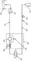
도 1은 본 발명의 원리에 따른 일체형 흡인 펌프를 구비한 핸드피스를 포함하는 수정체 유화 시스템의 유체 경로 내의 구성요소의 도면이다. 도 1은 백내장 수술 동안, 눈(145)을 통과하는 유체 경로를 도시한다. 구성요소에는 세정원(120), 선택적인 세정 압력 센서(130), 선택적인 세정 밸브(135), 세정 라인(140), 핸드피스(150), 흡인 라인(155), 선택적인 흡인 압력 센서(160), 선택적인 통기 밸브(165), 펌프(170), 저장통(175) 및 배수 포대(180)가 포함된다. 세정 라인(140)은 백내장 수술 동안 세정 유체를 눈(145)에 제공한다. 흡인 라인(155)은 백내장 수술 동안, 유체 및 유화된 수정체 조각들을 눈으로부터 제거한다.
BRIEF DESCRIPTION OF THE DRAWINGS Figure 1 is a diagram of components within the fluid path of a phantom emulsification system including a handpiece with an integral suction pump according to the principles of the present invention. Figure 1 shows the fluid path through the
세정 유체가 세정원(120)에서 나오면, 세정 유체는 세정 라인(140)을 통해 눈(145)으로 이동한다. 세정 압력 센서(130)가 세정 라인(140) 내의 세정 유체의 압력을 측정한다. 또한, 세정의 온/오프 제어를 위해 선택적인 세정 밸브(135)가 제공된다. 세정 압력 센서(130)는 다수의 구매 가능한 유체 압력 센서 중 하나에 의해 실현된다.
When the cleaning fluid exits the
수정체 유화술 절차 동안, 핸드피스(150)는 눈(145)에 대해 위치설정된다. 핸드피스(150)는 병에 걸린 수정체를 부수기 위해, 눈에서 초음파 진동을 일으키는 중공 바늘(도 2 및 도 3에서는 "270")을 구비한다. 바늘 주위에 위치되는 슬리브는 세정 라인(140)으로부터 세정 유체를 제공한다. 세정 유체는 바늘의 외부와 슬리브의 내부 사이의 공간을 통과한다. 유체와 수정체 조각은 중공 바늘을 통해 흡인된다. 이러한 방식으로, 중공 바늘의 내부 통로는 흡인 라인(155)에 유체 결합된다. 펌프(170)는 흡인된 유체를 눈(145)으로부터 인출해 낸다. 선택적인 흡인 압력 센서(160)가 흡인 라인의 압력을 측정한다. 선택적인 통기 밸브가 펌프(170)에 의해 생성된 진공을 통기시키는데 사용될 수 있다. 흡인된 유체는 저장통(175)을 통해 배수 포대(180)로 흐른다.
During the phacoemulsification procedure, the
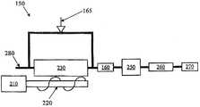
도 2는 본 발명의 원리에 따른 일체형 흡인 펌프를 구비한 수정체 유화 핸드피스의 블록도이다. 도 2에서, 핸드피스(150)는 모터(210), 샤프트(220), 제거 가능한 카트리지(230), 선택적인 흡인 압력 센서(160), 드라이버(250), 혼(260), 바늘(270) 및 흡인 라인(280)을 포함한다. 모터(210)는 샤프트(220)를 회전시킨다. 펌프 작동 시, 제거 가능한 카트리지(230)가 샤프트(220)에 대해 보유지지된다. 흡인 압력 센서(160)는 제거 가능한 카트리지(230)와 눈(145) 사이에 위치된다.
Figure 2 is a block diagram of a lens emulsion handpiece with an integral suction pump in accordance with the principles of the present invention. 2, the
도 2에서, 펌프(170)는 모터(210), 샤프트(220) 및 제거 가능한 카트리지(230) 내의 가요성 배관을 포함한다. 본 발명의 일 실시예에서, 샤프트(220)는 제거 가능한 카트리지(230) 내의 가요성 배관에 대해 가압하는 나선형 구조를 갖는다. 이러한 방식에서, 나사형 또는 스크롤 형 흡인 펌프는 모터(210), 샤프트(220) 및 제거 가능한 카트리지(230) 내의 가요성 배관으로 실현된다. 이는 도 4 및 도 5에 더욱 명확하게 도시 및 묘사된다. 펌프(170)가 나사형 펌프로서 설명되어 있지만, 다른 유형의 펌프도 사용될 수 있다.
In Figure 2, the
흡인 라인(280)은 제거 가능한 카트리지(230)에 유체 결합된다. 또한, 흡인 라인은 드라이버(250), 혼(260) 및 바늘(270)을 통과하거나 그 주위로 연장된다. 바늘(270) 내 루멘은 흡인 라인(280)에 유체 결합된다. 전술된 바와 같이, 유체 및 수정체 조각은 바늘(270)의 루멘을 통해 흡인된다. 흡인 펌프(170)는 바늘(270)의 루멘을 통해 유체 및 수정체 조각을 인입한다.
The
드라이버(250)는 전형적으로, 혼(260)에서 초음파 진동을 일으키는 초음파 드라이버이다. 혼(260)은 전형적으로, 드라이버(250) 및 바늘(270)에 결합되는 금속 뭉치이다. 이런 식으로, 드라이버(250)에 의해 생성된 진동이 혼(260) 및 바늘(270)로 이동된다. 바늘(270)이 눈에 위치되어 진동함으로써, 백내장의 수정체를 부순다.
The
흡인 압력 센서(160)는 흡인 라인(280) 내의 흡인 압력을 측정한다. 제거 가능한 카트리지(230)와 드라이버(250) 사이에 위치되는 것으로 도시되었지만, 흡인 압력 센서는 펌프(170)와 눈(145) 사이의 임의의 위치에 배치될 수도 있다. 흡인 압력 센서(160)는 공지된 다수의 압력 센서 장치 중 어느 하나에 의해 실현될 수 있다.
The
도 3은 본 발명의 원리에 따른 일체형 흡인 펌프를 구비한 수정체 유화 핸드피스의 블록도이다. 도 3의 예는 도 2의 요소들과, 선택적인 통기 밸브(165)를 갖는다. 선택적인 통기 밸브(165)가 존재하는 경우, 이는 흡인 펌프(170)용 통기 경로를 제공하는 역할을 한다. 이런 식으로, 핌프(170)는 예를 들어, 통기 밸브(165)가 개방된 경우, 대기로 통기될 수 있다. 도 3에 도시된 바와 같이, 흡인 라인(280)은 2개의 경로 - 제거 가능한 카트리지(230)를 통과하는 하나의 경로 및 제거 가능한 카트리지(230) 주위로 연장되는 다른 경로를 갖는다. 또한, [제거 가능한 카트리지(230) 주위로 연장되는] 이러한 제2 경로 및 관련된 통기 밸브(165)는 제거 가능한 카트리지(230)에 통합될 수도 있다. 통기 밸브(165)가 개방되는 경우, 대기로의 통기의 결과로서, 펌프(170)에 의해 생성되는 흡인 또는 진공은 감소된다.
3 is a block diagram of a lens emulsion handpiece with an integral suction pump in accordance with the principles of the present invention. The example of FIG. 3 has the elements of FIG. 2 and an
도 4 및 도 5는 각각, 본 발명의 원리에 따른 일체형 흡인 펌프를 구비한 수정체 유화 핸드피스의 일부에 대한 측면도 및 단면도이다. 도 4 및 도 5는 제거 가능한 카트리지(230) 및 펌프(170)의 일 예에 대한 상세를 더욱 명확하게 도시한다. 도시된 예에서, 제거 가능한 카트리지(230)는 흡인 라인 커플링(405), 제1 배관 커플링(420), 배관 홀더(440) 및 레버(430)를 포함한다. 이들 구성요소는 도시된 바와 같이 프레임에 일체화된다. 제거 가능한 카트리지(230)는 핸드피스의 나머지로부터 제거될 수 있다.
Figures 4 and 5 are side and cross-sectional views, respectively, of a portion of a lens emulsion handpiece with an integral suction pump in accordance with the principles of the present invention. Figures 4 and 5 more clearly illustrate details of one example of a
도 4 및 도 5에 도시된 제거 가능한 카트리지의 예에서, 흡인 라인 커플링(405)은 수술 콘솔에 결합되는 흡인 배관에 부착될 수 있다. 이런 식으로, 흡인 라인 커플링(405)은 수술 콘솔에 접속되는 핸드피스의 단부 근처에 있게 된다. 흡인 라인 커플링(405)으로부터 제1 배관 커플링(420)까지 튜브가 연장된다. 이 튜브는 도 2 및 도 3에 도시된 흡인 라인(280)의 일부이다.
In the example of the removable cartridge shown in FIGS. 4 and 5, the
배관 홀더(440)는 샤프트(220)와 배관 홀더(440) 사이에 위치되는 가요성 튜브(도시되지 않음)를 보유지지한다. 샤프트(220)는 배관 홀더(440)에 대해 가요성 배관을 가압한다. 샤프트(220)가 회전함에 따라, 샤프트(220) 상의 나선형 돌출부는 가요성 배관을 통해 유체를 펌핑한다(이로써, 나사형 또는 스크롤 형 펌프가 실현됨). 배관 홀더(440)는 가요성 배관을 보유지지하는데 적합한 강성 재료로 제조된다. 가요성 배관의 일단부는 제1 배관 커플링(420)에 유체 결합되고, 가요성 배관의 타단부는 제2 배관 커플링(425)에 유체 결합된다. 이런 방식에서, 가요성 배관은 흡인 라인(280)의 일부이다.
The
레버(430)는 제거 가능한 카트리지(230)를 핸드피스의 나머지 부분에 고정시키도록 작용한다. 레버로서 도시되어 있지만, 제거 가능한 카트리지를 핸드피스의 나머지 부분에 고정하는데에는 다른 기구가 사용될 수도 있다.
The
모터(210)는 샤프트(220)에 결합되어, 샤프트(220)를 회전시키는 역할을 한다. 모터(210)는 이하 보다 명확하게 설명되는 바와 같이, 샤프트(220)의 운동을 제어하도록 제어될 수 있다. 모터(210)는 전형적으로 DC 모터이지만, 샤프트(220)를 회전시키기에 적합한 임의의 유형의 모터 또는 드라이버일 수 있다.
The
도 4 및 도 5의 예에서, 커넥터(450)는 배관 홀더(440)에 의해 보유지지되는 가요성 배관을 핸드피스 커플링(415)에 연결한다. 커넥터 커플링(410)은 핸드피스 커플링(415)과 직접 또는 다른 부품을 개재하여 접속된다. 이런 식으로, 흡인 경로는 핸드피스 커플링(415), 커넥터 커플링(410), 커넥터(450), 제2 배관 커플링(425), 배관 홀더(440)에 의해 보유지지되는 가요성 배관, 제1 배관 커플링(420) 및 흡인 라인 커플링(405)을 통과한다. 커넥터(450)는 샤프트(220)의 단부에 접속된다. 이런 식으로, 커넥터(450), 샤프트(220) 및 모터(210)(이들 부품을 보유지지하는 프레임과 함께)는, [혼(260) 및 바늘(270)에 결합되는] 드라이버(250)에 부착된다.
In the example of Figures 4 and 5, the
펌프와 눈 사이[즉, 제2 배관 커플링(425)과 바늘(270) 사이]의 흡인 라인의 길이는 아주 짧다(수 인치 정도). 또한, 펌프와 눈 사이의 이러한 흡인 라인의 길이는 가변적이지 않을 수 있다(즉, 상기 길이는 고정적일 수 있다). 펌프(170)와 눈 사이의 비-가변식 배관의 작은 길이는 종래 기술의 시스템과 관련된 서지를 없앤다.
The length of the suction line between the pump and the eye (i.e., between the
작동 시, 모터(210)는 샤프트(220)를 회전시킨다. 제어기(도시되지 않음)가 모터(210)의 동작을 제어한다. 이런 식으로, 샤프트(220)는 임의의 요구되는 속도로 회전하여 임의의 요구되는 진공을 생성할 수 있다. 또한, 샤프트(220)는 요구되는 경우, 정지되거나 반대 방향으로 회전될 수 있다. 이런 식으로, 모터(210)는 각각의 방향으로 샤프트(220)를 회전시키도록 제어될 수 있다. 회전 시, 샤프트(220)는 가요성 튜브를 통해 유체를 이동시키고, 유체를 흡인 라인을 통해 펌핑시키는 역할을 한다.
In operation, the
다른 예에서, 샤프트(220)는 배관 홀더(440)에 대해 가까워지는 방향과 멀어지는 방향으로 이동될 수 있다. 이런 식으로, 배관 홀더(440)와 샤프트(220) 사이의 공간은, 가요성 배관이 샤프트(220)와 배관 홀더(440) 사이에서 상이한 정도로 죄여질 수 있도록 변경될 수 있다. 다시 말해, 샤프트(220)는 배관 홀더(440)에 의해 보유지지되는 가요성 배관을 매우 단단하게 조여 누설을 감안할 필요가 없는 펌핑 작용을 생성할 수 있다. 대안적으로, 샤프트(220)가 배관 홀더(440)로부터 멀어지는 방향으로 이동됨에 따라, 가요성 배관은 덜 단단히 죄여지고, 이로써 진공 또는 펌핑력의 누설 및 감소가 야기된다. 배관 홀더(440)에 대한 샤프트(220)의 위치는 가요성 배관을 통한 누설을 조정하고, 이에 따라 펌프에 의해 생성되는 진공을 조정하도록 가변적으로 제어될 수 있다.
In another example, the
다른 실시예(도 3에 도시됨)에서, 배관 홀더(440)에 대한 샤프트(220)의 위치는 고정될 수 있으며, 통기 밸브(165)는 펌프에 의해 생성되는 진공을 조정하는 누설을 생성하는데 사용될 수 있다. 이런 식으로, 통기 밸브(165)는 흡인 라인에 존재하는 진공의 양을 제어[통기 밸브(165)를 통한 누설의 양을 제어함으로써]하도록 가변적으로 제어될 수 있다.
In another embodiment (shown in FIG. 3), the position of the
흡인 진공의 제어는 흡인 압력 센서(160)로부터의 측정값에 기초할 수 있다. 흡인 압력 센서(160)는 펌프와 눈 사이에 위치된다. 이런 식으로, 흡인 압력 센서(160)는 눈에 매우 근접해 있는 흡인 라인의 압력 상태를 정확하게 나타낸다. 이러한 측정값은 눈에 적용되는 흡인 진공을 정밀하게 제어하는데 사용될 수 있다.
The control of the suction vacuum may be based on the measured value from the
도 6 및 도 7은 각각, 본 발명의 원리에 따른 일체형 흡인 펌프를 구비한 수정체 유화 핸드피스와 함께 사용하기 위한 제거 가능한 카트리지의 측면도 및 사시도이다. 도 6 및 도 7의 예에서, 제거 가능한 카트리지는 흡인 라인 커플링(405), 제1 배관 커플링(420), 배관 홀더(440), 레버(430) 및 개구(605)를 포함한다. 개구(605)는 도 5에 도시된 것과 같은 제2 배관 커플링(405)과 접속한다. 가요성 배관이 제1 배관 커플링(420)과 개구(605) 사이에 위치된다. 도 6 및 도 7의 제거 가능한 카트리지(230)는 재사용할 수 있거나 일회용일 수 있다. 일 예에서, 제거 가능한 카트리지는 재사용할 수 있고, 가요성 배관은 일회용이다. 다른 예에서, 제거 가능한 카트리지는 가요성 배관과 마찬가지로 일회용이다.
Figures 6 and 7 are respectively a side view and a perspective view of a removable cartridge for use with a catheter emulsion handpiece with an integral suction pump in accordance with the principles of the present invention. 6 and 7, the removable cartridge includes a
본 발명의 설계는 눈(145)에 매우 근접한 흡인 펌프(170)를 감안한다. 흡인 펌프(170)와 눈(145) 사이의 거리는 매우 짧게 이루어 질 수 있다 - 대략 수 인치. 흡인 펌프(170)를 눈(145)에 근접하여 위치시키는 것은 펌프(170)와 눈(145) 사이에 위치되는 매우 짧은 길이의 흡인 라인을 감안한다. 또한, 펌프(170)와 눈(145) 사이에 위치되는 흡인 라인의 길이는 고정될 수 있다(예를 들어, 흡인 라인은 스테인리스 스틸로 제조될 수 있음). 펌프(170)와 눈(145) 사이의 흡인 라인을 형성하는 비-가변식 재료의 이와 같은 짧은 길이는 종래의 수정체 유화 시스템과 관련된 임의의 서지 효과를 없앤다.
The design of the present invention contemplates a
종래의 수정체 유화 시스템에서, 흡인 펌프는 콘솔에 위치된다. 상대적으로 긴 길이(6 피트 이상)의 가요성 배관이 흡인 펌프와 눈 사이에 위치된다. 이러한 상대적으로 긴 길이의 가요성 배관은 많은 가변성을 갖는다 - 진공 압력의 변화에 응하여 연신될 수 있음. 이러한 가변성으로 인해, 전술한 바와 같은 서지가 야기된다. 흡인 펌프를 핸드피스에 통합시키고 (그리고 이를 눈에 매우 근접하여 위치시키고), 흡인 펌프와 눈 사이에서 비-가변식 배관의 길이를 매우 짧게 함으로써, 이러한 서지가 제거될 수 있기 때문에, 보다 안전하고 보다 효율적인 수술이 가능하다.
In a conventional phacoemulsification system, the suction pump is located at the console. A relatively long length (6 feet or more) of flexible tubing is located between the suction pump and the eye. This relatively long length of flexible piping has a great deal of variability - it can be stretched in response to changes in vacuum pressure. This variability leads to surges as described above. By integrating the suction pump into the handpiece (and placing it very close to the eye) and by making the length of the non-variable tubing between the suction pump and the eye very short, such a surge can be removed, More efficient surgery is possible.
전술한 바로부터, 본 발명은 수정체 유화 수술용 가압 주입 시스템을 제공한다는 것을 알 수 있다. 본 발명은 유체 압력을 보다 정밀하게 제어하는 세정 스퀴즈 밴드 장치를 제공한다. 본 명세서에 본 발명이 예시되며, 다양한 변형예들이 당업자에 의해 도출될 수 있다.
From the foregoing, it can be seen that the present invention provides a pressurized injection system for phacoemulsification surgery. The present invention provides a cleaning squeeze band device for more precisely controlling the fluid pressure. The present invention is illustrated herein, and various modifications may be derived by those skilled in the art.
본 발명의 다른 실시예들은 본 명세서에 개시된 본 발명의 실시 및 명세서를 고려할 때 당업자에게 명백할 것이다. 본 명세서 및 예들은 단지 예로서 고려되어야 하며, 본 발명의 진정한 범위 및 사상은 이하의 청구범위에 의해 명시되는 것으로 한다.Other embodiments of the invention will be apparent to those skilled in the art from consideration of the specification and practice of the invention disclosed herein. It is intended that the specification and examples be considered as exemplary only, with a true scope and spirit of the invention being indicated by the following claims.
Claims (8)
Translated fromKorean바늘과 결합하는 혼(horn)에 결합되는 드라이버; 및
상기 바늘에 가까이 위치되고, 상기 핸드피스와 일체인 흡인 펌프를 포함하고,
상기 흡인 펌프는,
모터;
상기 모터에 작동 가능하게 결합되는 샤프트; 및
가요성 배관을 포함하며,
상기 샤프트는 상기 가요성 배관에 대해 가압하도록 조정되는
눈 수술용 핸드피스.
As an eye surgical handpiece,
A driver coupled to a horn that engages the needle; And
And a suction pump located close to the needle and integral with the handpiece,
The suction pump includes:
motor;
A shaft operably coupled to the motor; And
A flexible piping,
The shaft is adapted to press against the flexible pipe
Eye surgical handpiece.
상기 흡인 펌프와 상기 바늘 사이에 위치되는 흡인 압력 센서를 더 포함하는
눈 수술용 핸드피스.
The method according to claim 1,
Further comprising a suction pressure sensor positioned between the suction pump and the needle
Eye surgical handpiece.
상기 흡인 펌프와 평행하게 위치되고, 상기 흡인 펌프에 의해 생성된 진공을 가변 제어하도록 가변 제어되는 통기 밸브를 더 포함하는
눈 수술용 핸드피스.
The method according to claim 1,
Further comprising a vent valve positioned in parallel with the suction pump and variably controlled to variably control the vacuum produced by the suction pump
Eye surgical handpiece.
상기 흡인 펌프와 상기 바늘 사이에 위치되는 고정 길이의 흡인 라인을 더 포함하고,
상기 가요성 배관에 대한 상기 샤프트의 위치가, 상기 고정 길이의 흡인 라인의 진공 압력을 감소시키는 누설을 결정하는
눈 수술용 핸드피스.
The method according to claim 1,
Further comprising a suction line of fixed length located between the suction pump and the needle,
Wherein the position of the shaft relative to the flexible pipe determines a leakage that reduces the vacuum pressure of the fixed length suction line
Eye surgical handpiece.
바늘과 결합하는 혼에 결합되는 드라이버;
상기 바늘에 가까이 위치되고, 상기 핸드피스와 일체인 흡인 펌프로서,
모터; 및
상기 모터에 작동 가능하게 결합되는 샤프트를 포함하는 흡인 펌프; 그리고
상기 흡인 펌프에 결합되는 일회용(diposable) 세그먼트를 포함하고,
상기 샤프트는 상기 일회용 세그먼트에 대해 가압하도록 조정되는
눈 수술용 핸드피스.
As an eye surgical handpiece,
A driver coupled to the horn to engage the needle;
A suction pump located close to the needle and integral with the handpiece,
motor; And
A suction pump including a shaft operably coupled to the motor; And
A diposable segment coupled to the suction pump,
The shaft is adapted to press against the disposable segment
Eye surgical handpiece.
상기 흡인 펌프와 상기 바늘 사이에 위치되는 흡인 압력 센서를 더 포함하는
눈 수술용 핸드피스.
6. The method of claim 5,
Further comprising a suction pressure sensor positioned between the suction pump and the needle
Eye surgical handpiece.
상기 흡인 펌프와 평행하게 위치되고, 상기 흡인 펌프에 의해 생성된 진공을 가변 제어하도록 가변 제어되는 통기 밸브를 더 포함하는
눈 수술용 핸드피스.
6. The method of claim 5,
Further comprising a vent valve positioned in parallel with the suction pump and variably controlled to variably control the vacuum produced by the suction pump
Eye surgical handpiece.
상기 흡인 펌프와 상기 바늘 사이에 위치되는 고정 길이의 흡인 라인을 더 포함하고,
상기 일회용 세그먼트에 대한 상기 샤프트의 위치가, 상기 고정 길이의 흡인 라인의 진공 압력을 감소시키는 누설을 결정하는
눈 수술용 핸드피스.6. The method of claim 5,
Further comprising a suction line of fixed length located between the suction pump and the needle,
Wherein the position of the shaft relative to the disposable segment determines the leakage that reduces the vacuum pressure of the suction line of the fixed length
Eye surgical handpiece.
Applications Claiming Priority (3)
| Application Number | Priority Date | Filing Date | Title |
|---|---|---|---|
| US12/633,363US20110137231A1 (en) | 2009-12-08 | 2009-12-08 | Phacoemulsification Hand Piece With Integrated Aspiration Pump |
| US12/633,363 | 2009-12-08 | ||
| PCT/US2010/058931WO2011071775A1 (en) | 2009-12-08 | 2010-12-03 | Phacoemulsification hand piece with integrated aspiration pump |
Publications (2)
| Publication Number | Publication Date |
|---|---|
| KR20120104283A KR20120104283A (en) | 2012-09-20 |
| KR101531829B1true KR101531829B1 (en) | 2015-06-26 |
Family
ID=44082714
Family Applications (1)
| Application Number | Title | Priority Date | Filing Date |
|---|---|---|---|
| KR1020127017536AExpired - Fee RelatedKR101531829B1 (en) | 2009-12-08 | 2010-12-03 | Phacoemulsification hand piece with integrated aspiration pump |
Country Status (21)
| Country | Link |
|---|---|
| US (3) | US20110137231A1 (en) |
| EP (1) | EP2509659B1 (en) |
| JP (3) | JP2013512760A (en) |
| KR (1) | KR101531829B1 (en) |
| CN (1) | CN102740905B (en) |
| AU (2) | AU2010328436B2 (en) |
| BR (1) | BR112012013848A2 (en) |
| CA (1) | CA2783155C (en) |
| CY (1) | CY1116140T1 (en) |
| DK (1) | DK2509659T3 (en) |
| ES (1) | ES2530735T3 (en) |
| HR (1) | HRP20150152T1 (en) |
| MX (1) | MX341706B (en) |
| PH (1) | PH12012501127A1 (en) |
| PL (1) | PL2509659T3 (en) |
| PT (1) | PT2509659E (en) |
| RS (1) | RS53810B1 (en) |
| RU (1) | RU2557911C2 (en) |
| SI (1) | SI2509659T1 (en) |
| SM (1) | SMT201500100B (en) |
| WO (1) | WO2011071775A1 (en) |
Cited By (2)
| Publication number | Priority date | Publication date | Assignee | Title |
|---|---|---|---|---|
| KR20210124298A (en)* | 2019-02-01 | 2021-10-14 | 칼 짜이스 메디텍 캐터랙트 테크놀로지 인크. | Ophthalmic Cutting Instrument with Integral Suction Pump |
| JP7753415B2 (en) | 2019-02-01 | 2025-10-14 | カール・ツァイス・メディテック・キャタラクト・テクノロジー・インコーポレイテッド | Ophthalmic cutting instrument with integrated suction pump |
Families Citing this family (56)
| Publication number | Priority date | Publication date | Assignee | Title |
|---|---|---|---|---|
| AU2009215477B2 (en)* | 2008-02-20 | 2014-10-23 | Mayo Foundation For Medical Education And Research | Systems, devices and methods for accessing body tissue |
| CA2715895A1 (en)* | 2008-02-20 | 2009-08-27 | Mayo Foundation For Medical Education And Research | Ultrasound guided systems and methods |
| US20110137231A1 (en)* | 2009-12-08 | 2011-06-09 | Alcon Research, Ltd. | Phacoemulsification Hand Piece With Integrated Aspiration Pump |
| US20110144567A1 (en)* | 2009-12-15 | 2011-06-16 | Alcon Research, Ltd. | Phacoemulsification Hand Piece With Integrated Aspiration Pump and Cartridge |
| US9795404B2 (en) | 2009-12-31 | 2017-10-24 | Tenex Health, Inc. | System and method for minimally invasive ultrasonic musculoskeletal tissue treatment |
| US8939949B2 (en) | 2011-08-15 | 2015-01-27 | Alcon Research, Ltd. | Stacked multi-disk ophthalmic pump |
| US9433725B2 (en) | 2011-12-23 | 2016-09-06 | Alcon Research, Ltd. | Combined coaxial and bimanual irrigation/aspiration apparatus |
| US10213533B2 (en)* | 2012-03-05 | 2019-02-26 | Keith A. Walter | Medical tools with aspiration tips suitable for cataract surgeries and related methods |
| US20130289469A1 (en)* | 2012-04-26 | 2013-10-31 | Karen T. Hong | Infusion Sleeve With Motion Reduction Profile |
| US10220186B2 (en) | 2012-05-23 | 2019-03-05 | Becton, Dickinson And Company | Collapse-resistant swellable catheter |
| US11406415B2 (en) | 2012-06-11 | 2022-08-09 | Tenex Health, Inc. | Systems and methods for tissue treatment |
| US9149291B2 (en) | 2012-06-11 | 2015-10-06 | Tenex Health, Inc. | Systems and methods for tissue treatment |
| NL2009424C2 (en) | 2012-09-06 | 2014-03-10 | D O R C Dutch Ophthalmic Res Ct International B V | Irrigation/aspiration system, cartridge, pump unit, surgical machine, method for controlling. |
| US9878075B2 (en)* | 2012-12-10 | 2018-01-30 | Alcon Research, Ltd. | Vacuum control method for surgical hand piece |
| CA2882220A1 (en) | 2012-12-11 | 2014-06-19 | Alcon Research Ltd. | Phacoemulsification hand piece with integrated aspiration and irrigation pump |
| US9962288B2 (en) | 2013-03-07 | 2018-05-08 | Novartis Ag | Active acoustic streaming in hand piece for occlusion surge mitigation |
| US9545337B2 (en) | 2013-03-15 | 2017-01-17 | Novartis Ag | Acoustic streaming glaucoma drainage device |
| US9750638B2 (en)* | 2013-03-15 | 2017-09-05 | Novartis Ag | Systems and methods for ocular surgery |
| US9126219B2 (en) | 2013-03-15 | 2015-09-08 | Alcon Research, Ltd. | Acoustic streaming fluid ejector |
| US9693896B2 (en) | 2013-03-15 | 2017-07-04 | Novartis Ag | Systems and methods for ocular surgery |
| US9915274B2 (en) | 2013-03-15 | 2018-03-13 | Novartis Ag | Acoustic pumps and systems |
| DK2986331T3 (en) | 2013-06-06 | 2019-02-18 | Novartis Ag | TRANSFORM IRRIGATION / EXTRACTION DEVICE |
| KR20160082968A (en)* | 2013-11-05 | 2016-07-11 | 노바르티스 아게 | Ophthalmic lubrication system and associated apparatus, systems, and methods |
| US10137034B2 (en) | 2013-11-26 | 2018-11-27 | Novartis Ag | Pressure-sensing vitrectomy surgical systems and methods |
| US9962181B2 (en) | 2014-09-02 | 2018-05-08 | Tenex Health, Inc. | Subcutaneous wound debridement |
| CN104161618A (en)* | 2014-09-10 | 2014-11-26 | 以诺康医疗科技(苏州)有限公司 | Ultrasonic emulsification handle |
| US20180058437A1 (en)* | 2015-02-16 | 2018-03-01 | The Regents Of The University Of Colorado, A Body Corporate | Pump with external controlled compression and methods of pumping with external controlled compression |
| US9763689B2 (en) | 2015-05-12 | 2017-09-19 | Tenex Health, Inc. | Elongated needles for ultrasonic applications |
| US10624785B2 (en) | 2016-01-30 | 2020-04-21 | Carl Zeiss Meditec Cataract Technology Inc. | Devices and methods for ocular surgery |
| US10278861B2 (en) | 2016-06-24 | 2019-05-07 | Novartis Ag | Phacoemulsification handpiece with flexible impeller pump |
| US11278450B2 (en) | 2017-05-04 | 2022-03-22 | Carl Zeiss Meditec Cataract Technology Inc. | Devices and methods for ocular surgery |
| US11071816B2 (en) | 2017-10-04 | 2021-07-27 | Johnson & Johnson Surgical Vision, Inc. | System, apparatus and method for monitoring anterior chamber intraoperative intraocular pressure |
| US11969380B2 (en) | 2017-10-04 | 2024-04-30 | Johnson & Johnson Surgical Vision, Inc. | Advanced occlusion management methods for a phacoemulsification system |
| EP3691585B1 (en) | 2017-10-04 | 2023-09-27 | Johnson & Johnson Surgical Vision, Inc. | Systems for measuring fluid flow in a venturi based system |
| WO2019069189A1 (en) | 2017-10-04 | 2019-04-11 | Johnson & Johnson Surgical Vision, Inc. | A system and method to augment irrigation pressure and to maintain iop during post occlusion surge |
| KR102782862B1 (en) | 2018-06-05 | 2025-03-19 | 칼 짜이스 메디텍 캐터랙트 테크놀로지 인크. | Ophthalmic Microsurgical Instruments, Systems and Methods of Use |
| CN108743019B (en)* | 2018-06-20 | 2020-05-12 | 太原爱尔眼科医院有限公司 | Femtosecond laser cataract emulsification treatment device |
| EP3826596A4 (en)* | 2018-07-24 | 2022-08-17 | Johnson & Johnson Surgical Vision, Inc. | SURGICAL INSTRUMENTS FOR EYE SURGERY |
| CN111281648B (en)* | 2018-12-08 | 2022-01-21 | 李聪 | Ultrasonic emulsification therapeutic instrument |
| US12171930B2 (en) | 2019-05-17 | 2024-12-24 | Johnson & Johnson Surgical Vision, Inc. | Ergonomic phacoemulsification handpiece |
| KR20220010739A (en) | 2019-05-17 | 2022-01-26 | 칼 짜이스 메디텍 캐터랙트 테크놀로지 인크. | Ophthalmic Cutting Instrument with Integral Suction Pump |
| RU2720821C1 (en)* | 2019-05-21 | 2020-05-13 | Александр Николаевич Епихин | System for irrigation and aspiration of ophthalmic apparatus for cataract and vitreal surgery |
| CA3142864A1 (en) | 2019-06-07 | 2020-12-10 | Carl Zeiss Meditec Cataract Technology Inc. | Multi-stage trigger for ophthalmology cutting tool |
| CA3145643A1 (en)* | 2019-07-01 | 2021-01-07 | Johnson & Johnson Surgical Vision, Inc. | Progressing aspiration pump in a surgical system |
| CN110338970B (en)* | 2019-07-23 | 2024-02-02 | 以诺康医疗科技(苏州)有限公司 | Ultrasonic emulsification handle with sensor and surge control system and method |
| RU2755271C1 (en)* | 2020-11-11 | 2021-09-14 | Закрытое акционерное общество "Оптимедсервис" | Ophthalmological fragmentator based on high-frequency vacuum oscillations |
| RU2755272C1 (en)* | 2020-11-12 | 2021-09-14 | Закрытое акционерное общество "Оптимедсервис" | Ophthalmological fragmentator based on vacuum oscillations |
| US12285360B2 (en) | 2020-12-22 | 2025-04-29 | Johnson & Johnson Surgical Vision, Inc. | Reducing irrigation/aspiration valve response time in a phacoemulsification system |
| US12129848B2 (en) | 2021-05-12 | 2024-10-29 | Johnson & Johnson Surgical Vision, Inc. | Disposable pump cartridge |
| US12016795B2 (en) | 2021-05-12 | 2024-06-25 | Johnson & Johnson Surgical Vision, Inc. | Clutch for disposable pump cartridge |
| US12137960B2 (en)* | 2021-05-25 | 2024-11-12 | Arthrex, Inc. | Surgical system with adaptive aspiration flow control |
| US12338816B2 (en)* | 2021-07-26 | 2025-06-24 | Johnson & Johnson Surgical Vision, Inc. | Progressive cavity pump cartridge with infrared temperature sensors on fluid inlet and outlet |
| US12427239B2 (en) | 2021-12-28 | 2025-09-30 | Johnson & Johnson Surgical Vision, Inc. | Pulse width modulation (PWM) operated vacuum relief valve in conjunction with an anti-vacuum surge (AVS) module |
| US12220139B2 (en) | 2022-03-20 | 2025-02-11 | Von Vascular, Inc. | System, devices and methods for removing obstructions in body lumens |
| US20230346597A1 (en)* | 2022-04-27 | 2023-11-02 | Johnson & Johnson Surgical Vision, Inc. | Jig to observe and quantify pressure pulse in phacoemulsification vacuum line |
| US12407980B2 (en) | 2023-03-01 | 2025-09-02 | Qsc, Llc | Customizable waveguides and associated systems and methods |
Citations (3)
| Publication number | Priority date | Publication date | Assignee | Title |
|---|---|---|---|---|
| US4861332A (en)* | 1986-04-14 | 1989-08-29 | Ultramed Corporation | Ultrasonic probe |
| US6117149A (en)* | 1992-11-30 | 2000-09-12 | Optex Ophthalmologics, Inc. | Rotary device and method for removing ophthalmic lens |
| WO2000053136A1 (en)* | 1999-03-08 | 2000-09-14 | Alcon Laboratories, Inc. | Surgical handpiece |
Family Cites Families (226)
| Publication number | Priority date | Publication date | Assignee | Title |
|---|---|---|---|---|
| US122381A (en)* | 1872-01-02 | Improvement in machines for making carpet-lining | ||
| US228146A (en)* | 1880-05-25 | Geoege w | ||
| US93989A (en)* | 1869-08-24 | Improvement in seeding-machines | ||
| US1061142A (en) | 1909-10-21 | 1913-05-06 | Nikola Tesla | Fluid propulsion |
| GB369037A (en)* | 1931-04-22 | 1932-03-17 | Yoshinobu Wada | Improvements in or relating to a pumping apparatus for medical treatments |
| US2015123A (en)* | 1934-05-11 | 1935-09-24 | Pennell Samuel | Blood transfusion apparatus |
| US2987004A (en) | 1955-07-29 | 1961-06-06 | Jerome L Murray | Fluid pressure device |
| US3447478A (en)* | 1967-03-03 | 1969-06-03 | Miles Lab | Peristaltic pump |
| NL145136C (en)* | 1967-07-25 | 1900-01-01 | ||
| US3487784A (en) | 1967-10-26 | 1970-01-06 | Edson Howard Rafferty | Pumps capable of use as heart pumps |
| US3996935A (en)* | 1969-02-14 | 1976-12-14 | Surgical Design Corporation | Surgical-type method for removing material |
| BE758029A (en) | 1969-10-27 | 1971-04-26 | Rhone Poulenc Sa | PERISTALTIC PUMP |
| FR2102904A5 (en) | 1970-08-28 | 1972-04-07 | Logeais Labor Jacques | |
| US4205948A (en) | 1977-02-10 | 1980-06-03 | Jones Allan R | Peristaltic pump |
| US4140118A (en) | 1977-03-09 | 1979-02-20 | Andros Incorporated | Cassette chamber for intravenous delivery system |
| US4187057A (en) | 1978-01-11 | 1980-02-05 | Stewart-Naumann Laboratories, Inc. | Peristaltic infusion pump and disposable cassette for use therewith |
| US4320761A (en)* | 1979-02-06 | 1982-03-23 | Haddad Heskel M | Surgical device for excision of tissue |
| US4255081A (en) | 1979-06-07 | 1981-03-10 | Oklejas Robert A | Centrifugal pump |
| FR2466641A1 (en) | 1979-09-27 | 1981-04-10 | Boeuf Lola Le | Peristaltic pump with conical rollers - has flexible tube compressed by rollers into groove of varying depth |
| JPS5825614B2 (en) | 1980-08-31 | 1983-05-28 | 重夫 中島 | Powder pressure feeding method and device |
| US4392794A (en) | 1980-12-29 | 1983-07-12 | Arthur Foxcroft | Peristaltic pump |
| AU564301B2 (en) | 1981-08-13 | 1987-08-06 | Commonwealth Scientific And Industrial Research Organisation | Reciprocatory piston and cylinder machine |
| US4493706A (en) | 1982-08-12 | 1985-01-15 | American Hospital Supply Corporation | Linear peristaltic pumping apparatus and disposable casette therefor |
| SU1209928A1 (en)* | 1982-11-15 | 1986-02-07 | Kozak Viktor | Peristaltic pump |
| US4479761A (en) | 1982-12-28 | 1984-10-30 | Baxter Travenol Laboratories, Inc. | Actuator apparatus for a prepackaged fluid processing module having pump and valve elements operable in response to externally applied pressures |
| US4537561A (en) | 1983-02-24 | 1985-08-27 | Medical Technology, Ltd. | Peristaltic infusion pump and disposable cassette for use therewith |
| JPS59154259U (en) | 1983-04-01 | 1984-10-16 | 株式会社ウベ循研 | Conical blood pump |
| DE3321151C2 (en)* | 1983-06-11 | 1986-09-18 | Walter Küsnacht Beck | Device for aspirating secretions |
| SE451541B (en) | 1983-06-30 | 1987-10-19 | Gambro Lundia Ab | EXTRACORPORAL BLOOD TREATMENT SYSTEM |
| US4684328A (en) | 1984-06-28 | 1987-08-04 | Piezo Electric Products, Inc. | Acoustic pump |
| US4657490A (en) | 1985-03-27 | 1987-04-14 | Quest Medical, Inc. | Infusion pump with disposable cassette |
| GB8510382D0 (en) | 1985-04-24 | 1985-05-30 | Russell D | Peristaltic pump |
| DK160633C (en) | 1985-05-15 | 1991-09-02 | Henning Munk Ejlersen | HOSE PUMP, ISSUE FOR EVENING AS INSULIN PUMP |
| US4713051A (en) | 1985-05-21 | 1987-12-15 | Coopervision, Inc. | Cassette for surgical irrigation and aspiration and sterile package therefor |
| US4935005A (en) | 1985-06-05 | 1990-06-19 | Nestle, S.A. | Opthalmic fluid flow control system |
| CA1280326C (en) | 1985-09-25 | 1991-02-19 | Leif Joakim Sundblom | Fast response tubeless vacuum aspiration collection cassette |
| US4768547A (en) | 1985-11-18 | 1988-09-06 | Critikon, Inc. | Parenteral solution pump assembly |
| US4909713A (en) | 1986-05-07 | 1990-03-20 | Cobe Laboratories, Inc. | Peristaltic pump |
| US4705500A (en)* | 1986-07-17 | 1987-11-10 | Mentor O & O, Inc. | Ophthalmic aspirator-irrigator |
| US4764165A (en) | 1986-07-17 | 1988-08-16 | Mentor O & O, Inc. | Ophthalmic aspirator-irrigator with valve |
| US4854825A (en) | 1987-02-27 | 1989-08-08 | Commonwealth Scientific And Industrial Research Organization | Multi-stage vacuum pump |
| SU1533696A1 (en) | 1987-04-22 | 1990-01-07 | Предприятие П/Я А-3697 | Peristaltic pump |
| US5195960A (en) | 1987-04-27 | 1993-03-23 | Site Microsurgical Systems, Inc. | Disposable vacuum/peristaltic pump cassette system |
| US4798580A (en)* | 1987-04-27 | 1989-01-17 | Site Microsurgical Systems, Inc. | Disposable peristaltic pump cassette system |
| US5125891A (en) | 1987-04-27 | 1992-06-30 | Site Microsurgical Systems, Inc. | Disposable vacuum/peristaltic pump cassette system |
| DE3850492T2 (en) | 1987-10-14 | 1995-02-16 | Nestle Sa | SURGICAL IRRIGATION AND SUCTION SYSTEM. |
| IT1220167B (en) | 1987-12-18 | 1990-06-06 | Renato Vicentini | PERFECT VOLUMETRIC PUMP FOR LIQUID OR GASEOUS FLUIDS |
| DE3809582A1 (en) | 1988-03-22 | 1989-10-12 | Franz Otto Dr Ing Kopp | Peristaltically operating diaphragm pump |
| JPH0270987A (en) | 1988-09-05 | 1990-03-09 | Terumo Corp | Roller pump |
| SU1590649A1 (en)* | 1988-10-27 | 1990-09-07 | Минский Филиал Всесоюзного Научно-Исследовательского И Проектно-Конструкторского Института Механизированного И Ручного Строительно-Монтажного Инструмента, Вибраторов И Строительно-Отделочных Машин | Peristaltic pump |
| US5046486A (en) | 1989-01-13 | 1991-09-10 | Stryker Corporation | Compact pulsing pump for irrigation handpiece |
| FR2644212B1 (en)* | 1989-03-13 | 1991-11-15 | Malbec Edouard | CASSETTE FOR PERISTALTIC PUMP WITH DEFORMABLE TUBE, AND PERISTALTIC PUMP EQUIPPED WITH SUCH A CASSETTE |
| US4963131A (en) | 1989-03-16 | 1990-10-16 | Surgin Surgical Instrumentation, Inc. | Disposable cassette for ophthalmic surgery applications |
| US4909710A (en) | 1989-10-23 | 1990-03-20 | Fisher Scientific Company | Linear peristaltic pump |
| US5041096A (en)* | 1989-10-27 | 1991-08-20 | Nestle, S.A. | Fluid handling method and system and fluid interface apparatus usable therewith |
| JPH03164586A (en) | 1989-11-22 | 1991-07-16 | Fujita Corp | Method and apparatus for force-feeding fluid by means of squeeze-type pump |
| US5106366A (en) | 1990-03-08 | 1992-04-21 | Nestle, S.A. | Medical fluid cassette and control system |
| US5038965A (en) | 1990-04-06 | 1991-08-13 | Spruhventile Gmbh | Pump dispenser for delivering a predetermined dosage regardless of method of actuation |
| US5957914A (en)* | 1990-06-19 | 1999-09-28 | Surgical Laser Technologies, Inc. | Photo optic breakdown probe |
| US6007513A (en)* | 1990-07-17 | 1999-12-28 | Aziz Yehia Anis | Removal of tissue |
| US5263830A (en)* | 1991-01-23 | 1993-11-23 | Sharp Kabushiki Kaisha | Peristaltic pump assembly |
| DE69212074T2 (en) | 1991-05-10 | 1996-11-07 | Terumo Corp | Liquid pump |
| US5316440A (en) | 1991-05-10 | 1994-05-31 | Terumo Kabushiki Kaisha | Blood pump apparatus |
| US5185002A (en)* | 1991-06-28 | 1993-02-09 | Alcon Surgical, Inc. | Transducer apparatus having water hammer dampening means |
| US5273517A (en) | 1991-07-09 | 1993-12-28 | Haemonetics Corporation | Blood processing method and apparatus with disposable cassette |
| US5207647A (en) | 1991-11-05 | 1993-05-04 | Phelps David Y | Needle device |
| US5267956A (en) | 1992-02-05 | 1993-12-07 | Alcon Surgical, Inc. | Surgical cassette |
| FR2690622B1 (en) | 1992-04-29 | 1995-01-20 | Chronotec | Programmable ambulatory infusion pump system. |
| FR2690715B1 (en) | 1992-04-30 | 1994-07-22 | Debiotech Sa | PERISTALTIC PUMP WITH CASSETTE PROVIDED WITH A DECORPAGE ASSEMBLY. |
| US5554013A (en) | 1992-05-01 | 1996-09-10 | Mcgaw, Inc. | Disposable cassette with negative head height fluid supply |
| US5302093A (en) | 1992-05-01 | 1994-04-12 | Mcgaw, Inc. | Disposable cassette with negative head height fluid supply and method |
| ATE161948T1 (en) | 1992-06-03 | 1998-01-15 | Allergan Inc | PRESSURE TRANSDUCER - INTERFACE |
| WO1993024082A1 (en) | 1992-06-03 | 1993-12-09 | Allergan, Inc. | Tubing management system |
| US5342181A (en) | 1992-06-15 | 1994-08-30 | Datascope Investment Corp. | Single roller blood pump and pump/oxygenator system using same |
| US5257917A (en) | 1992-10-02 | 1993-11-02 | Cole-Parmer Instrument Company | Peristaltic pump having means for reducing flow pulsation |
| GB2273533B (en) | 1992-12-18 | 1996-09-25 | Minnesota Mining & Mfg | Pumping cassette with integral manifold |
| US5403277A (en) | 1993-01-12 | 1995-04-04 | Minnesota Mining And Manufacturing Company | Irrigation system with tubing cassette |
| US5350357A (en) | 1993-03-03 | 1994-09-27 | Deka Products Limited Partnership | Peritoneal dialysis systems employing a liquid distribution and pumping cassette that emulates gravity flow |
| US6746419B1 (en)* | 1993-04-19 | 2004-06-08 | Stryker Corporation | Irrigation handpiece with built in pulsing pump |
| ATE168260T1 (en)* | 1993-05-07 | 1998-08-15 | Grieshaber & Co Ag | EYE SURGICAL DEVICE FOR Crushing and removing the lens nucleus from the eye of a living creature |
| US5868678A (en) | 1993-06-30 | 1999-02-09 | Medex, Inc. | Two-part medical pressure transducer with diaphragm stand-offs |
| US5514069A (en) | 1993-12-22 | 1996-05-07 | Baxter International Inc. | Stress-bearing umbilicus for a compact centrifuge |
| US5484239A (en) | 1993-12-22 | 1996-01-16 | Baxter International Inc. | Peristaltic pump and valve assembly for fluid processing systems |
| WO1995017218A1 (en) | 1993-12-22 | 1995-06-29 | Baxter International Inc. | Self-priming drip chamber with enhanced visibility |
| US5746708A (en) | 1993-12-22 | 1998-05-05 | Baxter International Inc. | Peristaltic pump tube holder with pump tube shield and cover |
| US5462416A (en) | 1993-12-22 | 1995-10-31 | Baxter International Inc. | Peristaltic pump tube cassette for blood processing systems |
| GB2285837B (en) | 1994-01-24 | 1998-05-13 | Varian Australia | Peristaltic pump |
| US5443370A (en) | 1994-05-02 | 1995-08-22 | Wang; Ro-Pin | Two cylinder manual air pump |
| US5460490A (en) | 1994-05-19 | 1995-10-24 | Linvatec Corporation | Multi-purpose irrigation/aspiration pump system |
| JP3679143B2 (en)* | 1994-06-30 | 2005-08-03 | 株式会社ニデック | Perfusion suction device |
| US5533976A (en) | 1994-07-15 | 1996-07-09 | Allergan, Inc. | Reusable cartridge assembly for a phaco machine |
| US5575632A (en) | 1994-09-12 | 1996-11-19 | Ivac Medical Systems, Inc. | Engineered pumping segment |
| US5573506A (en) | 1994-11-25 | 1996-11-12 | Block Medical, Inc. | Remotely programmable infusion system |
| US5542918A (en)* | 1995-01-06 | 1996-08-06 | Zimmer, Inc. | Vacuum driven fluid pump for an aspiration/irrigation instrument |
| US5910110A (en) | 1995-06-07 | 1999-06-08 | Mentor Ophthalmics, Inc. | Controlling pressure in the eye during surgery |
| US5630711A (en) | 1995-09-08 | 1997-05-20 | Graymills Corporation | Peristaltic pump having a loop-shaped tube path |
| US5588815A (en) | 1995-11-15 | 1996-12-31 | Alcon Laboratories, Inc. | Surgical cassette loading and unloading system |
| US6059544A (en) | 1995-12-01 | 2000-05-09 | Alcon Laboratories, Inc. | Identification system for a surgical cassette |
| US5705018A (en)* | 1995-12-13 | 1998-01-06 | Hartley; Frank T. | Micromachined peristaltic pump |
| US5759017A (en) | 1996-01-31 | 1998-06-02 | Medtronic Electromedics, Inc. | Peristaltic pump and tube loading system |
| US5688112A (en) | 1996-02-22 | 1997-11-18 | Garay; Thomas William | Rotor axis aligned tube and outlet for a peristaltic pump system |
| US5788667A (en)* | 1996-07-19 | 1998-08-04 | Stoller; Glenn | Fluid jet vitrectomy device and method for use |
| US5853386A (en) | 1996-07-25 | 1998-12-29 | Alaris Medical Systems, Inc. | Infusion device with disposable elements |
| FR2753235B1 (en) | 1996-09-10 | 1998-12-04 | Conseilray Sa | PORTABLE PERISTALTIC PUMP |
| US5733256A (en)* | 1996-09-26 | 1998-03-31 | Micro Medical Devices | Integrated phacoemulsification system |
| US5746719A (en) | 1996-10-25 | 1998-05-05 | Arthur D. Little, Inc. | Fluid flow control system incorporating a disposable pump cartridge |
| US6129699A (en) | 1997-10-31 | 2000-10-10 | Sorenson Development, Inc. | Portable persistaltic pump for peritoneal dialysis |
| JP3106980B2 (en) | 1996-11-07 | 2000-11-06 | 富士電機株式会社 | Liquid metering pump |
| US5899915A (en)* | 1996-12-02 | 1999-05-04 | Angiotrax, Inc. | Apparatus and method for intraoperatively performing surgery |
| US5879363A (en)* | 1997-03-18 | 1999-03-09 | Circuit Tree Medical, Inc. | Disposable surgical ultrasonic transducer |
| DE19711675A1 (en) | 1997-03-20 | 1998-10-01 | Fraunhofer Ges Forschung | Surgical hand instrument for removing tissue material in e.g. cataract surgery |
| US5897524A (en) | 1997-03-24 | 1999-04-27 | Wortrich; Theodore S. | Compact cassette for ophthalmic surgery |
| US6371934B1 (en)* | 1997-08-06 | 2002-04-16 | C. R. Bard, Inc. | Irrigation system and tip with debrider |
| WO1999011309A1 (en)* | 1997-08-29 | 1999-03-11 | Seiko Epson Corporation | Transfusion device and liquid supply tube |
| US5972012A (en)* | 1997-10-17 | 1999-10-26 | Angiotrax, Inc. | Cutting apparatus having articulable tip |
| US6012999A (en) | 1997-12-24 | 2000-01-11 | Patterson; Richard A. | Hydraulically-operated bicycle shifting system with positive pressure actuation |
| WO1999038549A1 (en) | 1998-01-28 | 1999-08-05 | Mentor Corporation | Tubing system to maintain fluid pressure during surgery |
| US6071639A (en)* | 1998-05-07 | 2000-06-06 | Itt Manufacturing Enterprises | Battery cartridge |
| US5927956A (en) | 1998-09-01 | 1999-07-27 | Linvatec Corporation | Peristaltic pump tubing system with latching cassette |
| US6214017B1 (en) | 1998-09-25 | 2001-04-10 | Sherwood Services Ag | Ultrasonic surgical apparatus |
| DE19856744C2 (en) | 1998-12-09 | 2003-06-26 | Plasmaselect Ag | Pump hose system for peristaltic delivery of liquid or gaseous media |
| US6058779A (en) | 1999-02-10 | 2000-05-09 | Cole; Mark S. | Coupled diaphragm interface for phacoemulsification apparatus |
| US6689146B1 (en)* | 1999-04-29 | 2004-02-10 | Stryker Corporation | Powered surgical handpiece with integrated irrigator and suction application |
| JP2002544439A (en) | 1999-05-12 | 2002-12-24 | ジー. ジョン アンデルセン, | Peristaltic pump |
| BR0011764A (en)* | 1999-06-18 | 2003-07-08 | Alcon Mfg Ltd | Infusion Control System |
| US6179808B1 (en) | 1999-06-18 | 2001-01-30 | Alcon Laboratories, Inc. | Method of controlling the operating parameters of a surgical system |
| US6416293B1 (en) | 1999-07-20 | 2002-07-09 | Deka Products Limited Partnership | Pumping cartridge including a bypass valve and method for directing flow in a pumping cartridge |
| US6604908B1 (en) | 1999-07-20 | 2003-08-12 | Deka Products Limited Partnership | Methods and systems for pulsed delivery of fluids from a pump |
| DE19936959A1 (en) | 1999-08-05 | 2001-02-15 | Wolf Gmbh Richard | Pinch valve for medical instruments and devices |
| US6261283B1 (en) | 1999-08-31 | 2001-07-17 | Alcon Universal Ltd. | Liquid venting surgical system and cassette |
| US20040253129A1 (en)* | 1999-08-31 | 2004-12-16 | Sorensen Gary P. | Liquid venting surgical cassette |
| US20010016706A1 (en) | 1999-08-31 | 2001-08-23 | Kurt D. Leukanech | Peristaltic pump |
| US6962488B2 (en) | 1999-11-10 | 2005-11-08 | Alcon, Inc. | Surgical cassette having an aspiration pressure sensor |
| US6293926B1 (en) | 1999-11-10 | 2001-09-25 | Alcon Universal Ltd. | Peristaltic pump and cassette |
| US6497680B1 (en) | 1999-12-17 | 2002-12-24 | Abbott Laboratories | Method for compensating for pressure differences across valves in cassette type IV pump |
| JP3529311B2 (en)* | 1999-12-22 | 2004-05-24 | 眞人 岸本 | Intraocular surgery device |
| US6296460B1 (en) | 2000-03-01 | 2001-10-02 | Steve C. Smith | Rotary cavity pump |
| CN2451084Y (en)* | 2000-05-26 | 2001-10-03 | 北京博达高科技有限公司 | Improvement of ultrasound cataract emulsion instrument transducer |
| GB0012931D0 (en) | 2000-05-26 | 2000-07-19 | Constance Ltd | Fluid bags |
| GB0012930D0 (en) | 2000-05-26 | 2000-07-19 | Constance Ltd | Peristaltic pumps |
| DE10034711B4 (en) | 2000-07-17 | 2006-04-20 | Fresenius Medical Care Deutschland Gmbh | sealing device |
| US20030153872A9 (en) | 2000-09-22 | 2003-08-14 | Tanner Howard M. C. | Apparatus and method for micro-volume infusion |
| EP1258260A3 (en) | 2000-10-04 | 2003-11-26 | Terumo Kabushiki Kaisha | Peritoneal dialysis apparatus |
| US6527765B2 (en)* | 2000-10-06 | 2003-03-04 | Charles D. Kelman | Cryogenic surgical system and method of use in removal of tissue |
| JP4752079B2 (en) | 2001-02-26 | 2011-08-17 | 株式会社ミクロン | Dental vacuum handpiece |
| WO2002077456A2 (en) | 2001-03-21 | 2002-10-03 | Innovent, Llc. | Inverted peristaltic pump |
| US6958058B1 (en)* | 2001-05-18 | 2005-10-25 | Medsafe Inc. | Methods and devices for pumping fluid and performing surgical procedures |
| US6890291B2 (en) | 2001-06-25 | 2005-05-10 | Mission Medical, Inc. | Integrated automatic blood collection and processing unit |
| US7018354B2 (en)* | 2001-11-08 | 2006-03-28 | El Hassane Tazi | Liposuction devices and methods and surrounding aspiration systems and methods |
| ITRM20010669A1 (en) | 2001-11-09 | 2003-05-09 | Optikon 2000 Spa | SUCTION INFUSION BOX (I / A) WITH SUCTION SYSTEM BOTH VIA PERISTALTIC PUMP OR OTHERWISE VOLUMETRIC THAN USING PR PUMP |
| US6599277B2 (en) | 2001-11-30 | 2003-07-29 | Bausch & Lomb Incorporated | Aspiration flow meter and control |
| DE10202378B4 (en) | 2002-01-23 | 2005-07-21 | Dürr Dental GmbH & Co. KG | Dental treatment device |
| US7063688B2 (en) | 2002-02-28 | 2006-06-20 | Say Family Trust | Portable battery operated aspirator |
| DE10209495C1 (en) | 2002-03-05 | 2003-10-30 | Wefis Vision Gmbh | Surgical instrument, in particular a phaco hollow needle |
| JP2003301778A (en) | 2002-04-10 | 2003-10-24 | Ckd Corp | Tube pump |
| US7087036B2 (en) | 2002-05-24 | 2006-08-08 | Baxter International Inc. | Fail safe system for operating medical fluid valves |
| US7238164B2 (en) | 2002-07-19 | 2007-07-03 | Baxter International Inc. | Systems, methods and apparatuses for pumping cassette-based therapies |
| DE10246469A1 (en)* | 2002-10-04 | 2004-04-15 | Applica Gmbh | Pump with peristaltic drive for medical applications, has cam segments with defined ratio between lamella height and stroke |
| DE10251598A1 (en) | 2002-11-06 | 2004-05-19 | A.M.I. Agency For Medical Innovations Gmbh | Surgical cleaning and suction device for uses in operating field has reservoirs for fresh fluid and fluid sucked back from distal end of tubular lance |
| US7150607B2 (en) | 2002-11-18 | 2006-12-19 | International Remote Imaging Systems, Inc. | Uniform flow displacement pump |
| RU2241887C1 (en) | 2003-02-28 | 2004-12-10 | Авилкин Юрий Михайлович | Valve unit of pump |
| US7238010B2 (en)* | 2003-04-14 | 2007-07-03 | Stryker Corporation | Surgical irrigation pump and tool system |
| US7645127B2 (en) | 2003-04-29 | 2010-01-12 | Loren Hagen | Pulseless peristaltic pump |
| WO2004110524A2 (en)* | 2003-06-06 | 2004-12-23 | Phacor, Inc. | Fluid-flow cassette for an ophthalmic surgical instrument |
| US7001153B2 (en)* | 2003-06-30 | 2006-02-21 | Blue-White Industries | Peristaltic injector pump leak monitor |
| CN1829545B (en) | 2003-07-31 | 2010-06-16 | 生物技术公司 | system for performing peritoneal dialysis |
| US20050049539A1 (en) | 2003-09-03 | 2005-03-03 | O'hara Gerald P. | Control system for driving fluids through an extracorporeal blood circuit |
| US7168930B2 (en)* | 2003-09-29 | 2007-01-30 | Bausch & Lomb Incorporated | Peristaltic pump with air venting via the movement of a pump head or a backing plate during surgery |
| US7445436B2 (en) | 2003-09-29 | 2008-11-04 | Bausch & Lomb Incorporated | Peristaltic pump with a moveable pump head |
| US7632078B2 (en) | 2003-10-30 | 2009-12-15 | Deka Products Limited Partnership | Pump cassette bank |
| US7776006B2 (en) | 2003-11-05 | 2010-08-17 | Baxter International Inc. | Medical fluid pumping system having real time volume determination |
| US8038639B2 (en) | 2004-11-04 | 2011-10-18 | Baxter International Inc. | Medical fluid system with flexible sheeting disposable unit |
| US7273359B2 (en) | 2003-11-05 | 2007-09-25 | Linvatec Corporation | Peristaltic irrigation pump system |
| US7959608B2 (en)* | 2004-04-27 | 2011-06-14 | The Spectranetics Corporation | Thrombectomy and soft debris removal device |
| US20050271531A1 (en)* | 2004-06-03 | 2005-12-08 | Brown William R Jr | Oral care device |
| US20060000925A1 (en) | 2004-06-30 | 2006-01-05 | Maher Colin G | Reduced sized micro-fluid jet nozzle structure |
| US8591464B2 (en) | 2004-08-27 | 2013-11-26 | Atul Kumar | Low turbulence fluid management system for endoscopic procedures |
| US8252321B2 (en)* | 2004-09-13 | 2012-08-28 | Chrono Therapeutics, Inc. | Biosynchronous transdermal drug delivery for longevity, anti-aging, fatigue management, obesity, weight loss, weight management, delivery of nutraceuticals, and the treatment of hyperglycemia, alzheimer's disease, sleep disorders, parkinson's disease, aids, epilepsy, attention deficit disorder, nicotine addiction, cancer, headache and pain control, asthma, angina, hypertension, depression, cold, flu and the like |
| US20060074345A1 (en) | 2004-09-29 | 2006-04-06 | Hibner John A | Biopsy apparatus and method |
| US20060184091A1 (en)* | 2005-02-14 | 2006-08-17 | Alcon, Inc. | Liquefaction handpiece |
| US20060253194A1 (en) | 2005-05-05 | 2006-11-09 | Dial Discoveries, Llc | Devices and methods for displacing biological fluids incorporating stacked disc impeller systems |
| EP1909864B1 (en) | 2005-06-13 | 2012-10-17 | Smith & Nephew, Inc. | Surgical fluid management |
| US7648465B2 (en)* | 2005-06-28 | 2010-01-19 | Alcon, Inc. | Method of testing a surgical system |
| US20070078379A1 (en)* | 2005-08-31 | 2007-04-05 | Alcon, Inc. | Controlling a phacoemulsification surgical system by transitioning between pulse and burst modes |
| US20070135760A1 (en) | 2005-12-14 | 2007-06-14 | Williams David L | Occlusion clearance in microsurgical system |
| US8500421B2 (en) | 2005-12-31 | 2013-08-06 | Novartis Ag | System and method operable to prevent tubing displacement within a peristaltic pump |
| US7775780B2 (en) | 2006-01-24 | 2010-08-17 | Alcon, Inc. | Surgical cassette |
| US20070217919A1 (en) | 2006-03-14 | 2007-09-20 | Alcon, Inc. | Peristaltic pump |
| US8303542B2 (en) | 2006-06-10 | 2012-11-06 | Bausch & Lomb Incorporated | Ophthalmic surgical cassette and system |
| US8480625B2 (en) | 2006-10-23 | 2013-07-09 | Bausch & Lamb Incorporated | Grooved aspiration pump roller-head assembly |
| WO2008053259A1 (en) | 2006-10-30 | 2008-05-08 | Gambro Lundia Ab | Hemo(dia)filtration apparatus |
| US9033940B2 (en) | 2006-11-09 | 2015-05-19 | Abbott Medical Optics Inc. | Eye treatment system with fluidics pump interface |
| US8491528B2 (en) | 2006-11-09 | 2013-07-23 | Abbott Medical Optics Inc. | Critical alignment of fluidics cassettes |
| US7967777B2 (en) | 2006-11-09 | 2011-06-28 | Abbott Medical Optics Inc. | Eye treatment system with multiple pumps |
| US9295765B2 (en) | 2006-11-09 | 2016-03-29 | Abbott Medical Optics Inc. | Surgical fluidics cassette supporting multiple pumps |
| US8414534B2 (en) | 2006-11-09 | 2013-04-09 | Abbott Medical Optics Inc. | Holding tank devices, systems, and methods for surgical fluidics cassette |
| US10959881B2 (en) | 2006-11-09 | 2021-03-30 | Johnson & Johnson Surgical Vision, Inc. | Fluidics cassette for ocular surgical system |
| US20100286791A1 (en)* | 2006-11-21 | 2010-11-11 | Goldsmith David S | Integrated system for the ballistic and nonballistic infixion and retrieval of implants |
| US7695242B2 (en) | 2006-12-05 | 2010-04-13 | Fuller Howard J | Wind turbine for generation of electric power |
| CN200991440Y (en) | 2006-12-29 | 2007-12-19 | 武汉半边天医疗技术发展有限公司 | Cystis suction pump |
| EP1970081A1 (en) | 2007-03-12 | 2008-09-17 | Jean-Denis Rochat | Enteral or parenteral or perfusion nutrition pumping unit |
| CN101765414B (en)* | 2007-04-20 | 2013-09-25 | 多汉尼眼科研究所 | Independent surgical center |
| US7540855B2 (en) | 2007-06-01 | 2009-06-02 | Peregrine Surgical, Ltd. | Disposable aspirator cassette |
| JP5199348B2 (en)* | 2007-06-19 | 2013-05-15 | アルコン リサーチ, リミテッド | Post-occlusion chamber collapse canceling device for surgical apparatus and method of use thereof |
| US7901376B2 (en) | 2007-07-05 | 2011-03-08 | Baxter International Inc. | Dialysis cassette having multiple outlet valve |
| US20090018488A1 (en) | 2007-07-09 | 2009-01-15 | Davis Sherman G | Method of Priming a Surgical System |
| US8162633B2 (en) | 2007-08-02 | 2012-04-24 | Abbott Medical Optics Inc. | Volumetric fluidics pump with translating shaft path |
| WO2009029666A1 (en) | 2007-08-27 | 2009-03-05 | Quest Medical, Inc. | Two-chamber blood pump |
| DE102007044790A1 (en) | 2007-09-19 | 2009-04-02 | Dieter Mann | One-hand device for eye surgery |
| US7892332B2 (en) | 2007-10-01 | 2011-02-22 | Baxter International Inc. | Dialysis systems having air traps with internal structures to enhance air removal |
| JP5883562B2 (en) | 2008-02-27 | 2016-03-15 | スミス アンド ネフュー インコーポレーテッド | Peristaltic pump apparatus and method |
| US20090246035A1 (en) | 2008-03-28 | 2009-10-01 | Smiths Medical Asd, Inc. | Pump Module Fluidically Isolated Displacement Device |
| US8449495B2 (en) | 2008-05-28 | 2013-05-28 | Baxter Healthcare Inc. | Dialysis system having automated effluent sampling and peritoneal equilibration test |
| DE102008026916A1 (en) | 2008-06-05 | 2009-12-17 | Fresenius Medical Care Deutschland Gmbh | Organizer for releasably receiving components of blood tubing sets and methods of making and preparing same |
| US8523539B2 (en) | 2008-06-19 | 2013-09-03 | The Board Of Regents Of The University Of Texas Systems | Centrifugal pump |
| WO2010054145A1 (en) | 2008-11-07 | 2010-05-14 | Abbott Medical Optics Inc. | Surgical cassette apparatus |
| AU2009313402C1 (en) | 2008-11-07 | 2015-10-15 | Johnson & Johnson Surgical Vision, Inc. | Automatically switching different aspiration levels and/or pumps to an ocular probe |
| US8998864B2 (en) | 2008-11-14 | 2015-04-07 | Bausch & Lomb Incorporated | Ophthalmic surgical cassettes for ophthalmic surgery |
| US9044544B2 (en) | 2008-11-21 | 2015-06-02 | Baxter International Inc. | Dialysis machine having auto-connection system with roller occluder |
| EP2349377B1 (en) | 2008-11-28 | 2017-04-05 | Terumo Kabushiki Kaisha | Blood bag system and cassette |
| WO2010080894A2 (en)* | 2009-01-07 | 2010-07-15 | Enlighten Technologies, Inc. | Tissue removal devices, systems and methods |
| CN102413849B (en) | 2009-05-06 | 2015-02-11 | 爱尔康研究有限公司 | Multiple segmented peristaltic pump and cassette |
| US20110137231A1 (en)* | 2009-12-08 | 2011-06-09 | Alcon Research, Ltd. | Phacoemulsification Hand Piece With Integrated Aspiration Pump |
| US20110144567A1 (en)* | 2009-12-15 | 2011-06-16 | Alcon Research, Ltd. | Phacoemulsification Hand Piece With Integrated Aspiration Pump and Cartridge |
| US20110313343A1 (en) | 2010-06-18 | 2011-12-22 | Alcon Research, Ltd. | Phacoemulsification Fluidics System Having a Single Pump Head |
| WO2012048261A2 (en) | 2010-10-07 | 2012-04-12 | Vanderbilt University | Peristaltic micropump and related systems and methods |
- 2009
- 2009-12-08USUS12/633,363patent/US20110137231A1/ennot_activeAbandoned
- 2010
- 2010-12-03CNCN201080061345.8Apatent/CN102740905B/ennot_activeExpired - Fee Related
- 2010-12-03RURU2012128589/14Apatent/RU2557911C2/ennot_activeIP Right Cessation
- 2010-12-03PTPT10836456Tpatent/PT2509659E/enunknown
- 2010-12-03AUAU2010328436Apatent/AU2010328436B2/ennot_activeCeased
- 2010-12-03BRBR112012013848Apatent/BR112012013848A2/enactiveSearch and Examination
- 2010-12-03PHPH1/2012/501127Apatent/PH12012501127A1/enunknown
- 2010-12-03CACA2783155Apatent/CA2783155C/ennot_activeExpired - Fee Related
- 2010-12-03HRHRP20150152TTpatent/HRP20150152T1/enunknown
- 2010-12-03DKDK10836456.3Tpatent/DK2509659T3/enactive
- 2010-12-03ESES10836456Tpatent/ES2530735T3/enactiveActive
- 2010-12-03JPJP2012543171Apatent/JP2013512760A/ennot_activeWithdrawn
- 2010-12-03MXMX2012006474Apatent/MX341706B/enactiveIP Right Grant
- 2010-12-03SISI201030909Tpatent/SI2509659T1/enunknown
- 2010-12-03RSRS20150067Apatent/RS53810B1/enunknown
- 2010-12-03PLPL10836456Tpatent/PL2509659T3/enunknown
- 2010-12-03KRKR1020127017536Apatent/KR101531829B1/ennot_activeExpired - Fee Related
- 2010-12-03EPEP10836456.3Apatent/EP2509659B1/enactiveActive
- 2010-12-03WOPCT/US2010/058931patent/WO2011071775A1/enactiveApplication Filing
- 2011
- 2011-12-14USUS13/325,549patent/US9861522B2/enactiveActive
- 2013
- 2013-11-19AUAU2013257535Apatent/AU2013257535B2/ennot_activeCeased
- 2015
- 2015-03-24CYCY20151100299Tpatent/CY1116140T1/enunknown
- 2015-04-23SMSM201500100Tpatent/SMT201500100B/enunknown
- 2015-09-16JPJP2015182632Apatent/JP2016027872A/ennot_activeWithdrawn
- 2017
- 2017-08-03JPJP2017150526Apatent/JP6334787B2/enactiveActive
- 2017-10-30USUS15/797,505patent/US20180049921A1/ennot_activeAbandoned
Patent Citations (3)
| Publication number | Priority date | Publication date | Assignee | Title |
|---|---|---|---|---|
| US4861332A (en)* | 1986-04-14 | 1989-08-29 | Ultramed Corporation | Ultrasonic probe |
| US6117149A (en)* | 1992-11-30 | 2000-09-12 | Optex Ophthalmologics, Inc. | Rotary device and method for removing ophthalmic lens |
| WO2000053136A1 (en)* | 1999-03-08 | 2000-09-14 | Alcon Laboratories, Inc. | Surgical handpiece |
Cited By (4)
| Publication number | Priority date | Publication date | Assignee | Title |
|---|---|---|---|---|
| KR20210124298A (en)* | 2019-02-01 | 2021-10-14 | 칼 짜이스 메디텍 캐터랙트 테크놀로지 인크. | Ophthalmic Cutting Instrument with Integral Suction Pump |
| JP2024056797A (en)* | 2019-02-01 | 2024-04-23 | カール・ツァイス・メディテック・キャタラクト・テクノロジー・インコーポレイテッド | Ophthalmic cutting instrument with integrated suction pump - Patent Application 20070123333 |
| KR102782067B1 (en) | 2019-02-01 | 2025-03-18 | 칼 짜이스 메디텍 캐터랙트 테크놀로지 인크. | Ophthalmic cutting device with integral suction pump |
| JP7753415B2 (en) | 2019-02-01 | 2025-10-14 | カール・ツァイス・メディテック・キャタラクト・テクノロジー・インコーポレイテッド | Ophthalmic cutting instrument with integrated suction pump |
Also Published As
Similar Documents
| Publication | Publication Date | Title |
|---|---|---|
| KR101531829B1 (en) | Phacoemulsification hand piece with integrated aspiration pump | |
| US20110144567A1 (en) | Phacoemulsification Hand Piece With Integrated Aspiration Pump and Cartridge | |
| JP5587986B2 (en) | Pressure perfusion squeeze band | |
| US9314553B2 (en) | Surgical system | |
| EP1852095A1 (en) | Irrigation/aspiration tip | |
| US20160089268A1 (en) | Phacoemulsification hand piece with integrated venturi aspiration pump | |
| EP1716828A1 (en) | Low resistance irrigation system and apparatus | |
| EP1647248A1 (en) | Low resistance irrigation system |
Legal Events
| Date | Code | Title | Description |
|---|---|---|---|
| PA0105 | International application | St.27 status event code:A-0-1-A10-A15-nap-PA0105 | |
| PG1501 | Laying open of application | St.27 status event code:A-1-1-Q10-Q12-nap-PG1501 | |
| R17-X000 | Change to representative recorded | St.27 status event code:A-3-3-R10-R17-oth-X000 | |
| A201 | Request for examination | ||
| PA0201 | Request for examination | St.27 status event code:A-1-2-D10-D11-exm-PA0201 | |
| E902 | Notification of reason for refusal | ||
| PE0902 | Notice of grounds for rejection | St.27 status event code:A-1-2-D10-D21-exm-PE0902 | |
| P11-X000 | Amendment of application requested | St.27 status event code:A-2-2-P10-P11-nap-X000 | |
| P13-X000 | Application amended | St.27 status event code:A-2-2-P10-P13-nap-X000 | |
| E701 | Decision to grant or registration of patent right | ||
| PE0701 | Decision of registration | St.27 status event code:A-1-2-D10-D22-exm-PE0701 | |
| GRNT | Written decision to grant | ||
| PR0701 | Registration of establishment | St.27 status event code:A-2-4-F10-F11-exm-PR0701 | |
| PR1002 | Payment of registration fee | St.27 status event code:A-2-2-U10-U12-oth-PR1002 Fee payment year number:1 | |
| PG1601 | Publication of registration | St.27 status event code:A-4-4-Q10-Q13-nap-PG1601 | |
| FPAY | Annual fee payment | Payment date:20180529 Year of fee payment:4 | |
| PR1001 | Payment of annual fee | St.27 status event code:A-4-4-U10-U11-oth-PR1001 Fee payment year number:4 | |
| FPAY | Annual fee payment | Payment date:20190530 Year of fee payment:5 | |
| PR1001 | Payment of annual fee | St.27 status event code:A-4-4-U10-U11-oth-PR1001 Fee payment year number:5 | |
| PN2301 | Change of applicant | St.27 status event code:A-5-5-R10-R11-asn-PN2301 | |
| PN2301 | Change of applicant | St.27 status event code:A-5-5-R10-R14-asn-PN2301 | |
| PN2301 | Change of applicant | St.27 status event code:A-5-5-R10-R14-asn-PN2301 | |
| PC1903 | Unpaid annual fee | St.27 status event code:A-4-4-U10-U13-oth-PC1903 Not in force date:20200623 Payment event data comment text:Termination Category : DEFAULT_OF_REGISTRATION_FEE | |
| R18-X000 | Changes to party contact information recorded | St.27 status event code:A-5-5-R10-R18-oth-X000 | |
| PC1903 | Unpaid annual fee | St.27 status event code:N-4-6-H10-H13-oth-PC1903 Ip right cessation event data comment text:Termination Category : DEFAULT_OF_REGISTRATION_FEE Not in force date:20200623 |