KR101531748B1 - The noumenon a straw cutter - Google Patents
The noumenon a straw cutterDownload PDFInfo
- Publication number
- KR101531748B1 KR101531748B1KR1020130059506AKR20130059506AKR101531748B1KR 101531748 B1KR101531748 B1KR 101531748B1KR 1020130059506 AKR1020130059506 AKR 1020130059506AKR 20130059506 AKR20130059506 AKR 20130059506AKR 101531748 B1KR101531748 B1KR 101531748B1
- Authority
- KR
- South Korea
- Prior art keywords
- movable blade
- support
- blade
- pedestal
- vertical support
- Prior art date
- Legal status (The legal status is an assumption and is not a legal conclusion. Google has not performed a legal analysis and makes no representation as to the accuracy of the status listed.)
- Active
Links
Images


Classifications
- B—PERFORMING OPERATIONS; TRANSPORTING
- B26—HAND CUTTING TOOLS; CUTTING; SEVERING
- B26D—CUTTING; DETAILS COMMON TO MACHINES FOR PERFORATING, PUNCHING, CUTTING-OUT, STAMPING-OUT OR SEVERING
- B26D1/00—Cutting through work characterised by the nature or movement of the cutting member or particular materials not otherwise provided for; Apparatus or machines therefor; Cutting members therefor
- B26D1/01—Cutting through work characterised by the nature or movement of the cutting member or particular materials not otherwise provided for; Apparatus or machines therefor; Cutting members therefor involving a cutting member which does not travel with the work
- B26D1/12—Cutting through work characterised by the nature or movement of the cutting member or particular materials not otherwise provided for; Apparatus or machines therefor; Cutting members therefor involving a cutting member which does not travel with the work having a cutting member moving about an axis
- B26D1/25—Cutting through work characterised by the nature or movement of the cutting member or particular materials not otherwise provided for; Apparatus or machines therefor; Cutting members therefor involving a cutting member which does not travel with the work having a cutting member moving about an axis with a non-circular cutting member
- B26D1/26—Cutting through work characterised by the nature or movement of the cutting member or particular materials not otherwise provided for; Apparatus or machines therefor; Cutting members therefor involving a cutting member which does not travel with the work having a cutting member moving about an axis with a non-circular cutting member moving about an axis substantially perpendicular to the line of cut
- B26D1/30—Cutting through work characterised by the nature or movement of the cutting member or particular materials not otherwise provided for; Apparatus or machines therefor; Cutting members therefor involving a cutting member which does not travel with the work having a cutting member moving about an axis with a non-circular cutting member moving about an axis substantially perpendicular to the line of cut with limited pivotal movement to effect cut
Landscapes
- Life Sciences & Earth Sciences (AREA)
- Forests & Forestry (AREA)
- Engineering & Computer Science (AREA)
- Mechanical Engineering (AREA)
- Knives (AREA)
Abstract
Translated fromKoreanDescription
Translated fromKorean본 발명은 작두 본체에 관한 것이며 보다 상세하게는 받침날과 가동날의 일방 선단은 힌지 조립되고, 가동날의 후방에는 손잡이가 구비되며, 작두 본체는 받침날과 받침대를 일체형으로 하고, 상기 받침날 후방에는 가동날의 손잡이가 받침날 하방이나 외측으로 밀려나오지 않도록 받침턱을 구비한 것이다.More particularly, the present invention relates to a main body, and more particularly, to a structure in which one end of a support blade and a movable blade are hingedly assembled, and a handle is provided on the rear side of the movable blade. And a support jaw is provided at the rear so that the handle of the movable blade is prevented from being pushed downward or outward of the support blade.
작두는 작두 본체 선단에 U형의 작두날 결합부를 구비하고, 상기 U형의 작두날 결합부에 가동날 선단을 위치시켜서 힌지 조립하고, 가동날의 후방에는 손잡이를 구비하여서 구성되고, 상기 작두 본체와 가동날 사이에 피절단물을 위치시켜서 가동날을 하방으로 내리면 피절단물이 절단되도록 한 도구를 의미하고 있다.A movable blade tip is disposed at the tip of the U-shaped conical blade to hinge-assemble the movable blade, and a handle is provided at the rear of the movable blade, Means that the workpiece is cut between the movable blade and the movable blade when the movable blade is lowered by positioning the workpiece between the movable blade and the movable blade.
상기 작두는 우사에서 소의 먹이인 생초나 건초 및 짚을 썰 때, 한약재를 규격으로 썰 때, 식품 고장이나 가정에서 무, 배추, 고기 등의 식재료를 썰 때 등 다양하게 사용된다.The above quotation is used variously when cutting raw herb, hay and straw, cutting herb medicine to standard, cutting food such as radish, Chinese cabbage and meat at home, and so on.
상기 작두에서 작두 본체는 대체적으로 목재로 된 받침판 선단에 금속재로 된 U형의 작두날 결합부를 구비하여서 구성하거나 또는 목재로 된 받침판 위에 L자형의 받침날을 고정 설치하여서 구성되는데, 전자의 작두 본체는 받침날이 구비되지 않아서 피절단물의 절단이 어려운 결점이 있고, 후자의 작두 본체는 받침날이 구비되어 피절단물의 절단이 용이한 이점으로 주로 사용되고 있다.In the above description, the main body is generally constituted by a U-shaped small-blade coupling part made of a metal material at the tip of a wooden base plate, or an L-shaped support blade is fixedly mounted on a wooden base plate. There is a disadvantage in that the cutting object is difficult to cut and the cutting object is difficult to cut. The latter main body is mainly used with an advantage that the cutting object can be easily cut by the supporting blade.
상기 작두 본체는 받침판은 목재판 위에 금속재의 받침날을 고정하여야 하고, 또 받침판의 길이와 받침날의 길이를 동일하게 하므로 가동날의 손잡이가 받침날 보다 길어야 하므로 사용시에는 받침판 후방으로 하중이 쏠리게 되므로 받침판의 기능이 상실되고 받침판 위에 설치되는 받침날의 길이를 짧게 하면 견고성이 떨어지고 또 가동날의 손잡이를 내릴 때 가동날의 손잡이가 받침판까지 하강되므로 사용자가 가동날의 손잡이를 잡고 사용하게 되면 사용자의 손이 받침판을 치게 되어 상해를 입게 되는 결점이 지적되고 있다.Since the base plate has a metal plate on the wood plate and the length of the plate is equal to the length of the base plate, the handle of the movable plate must be longer than the base plate. If the support plate is lost and the length of the support blade installed on the support plate is shortened, the robustness is decreased. When the handle of the movable blade is lowered, the handle of the movable blade is lowered to the support plate. It is pointed out that the hand is hit by the base plate and it causes injury.
본 발명은 상기 지적의 종래 결점들을 해소하고 금속판재를 절곡하여서 구성하고 받침날의 하방 좌우에는 대각으로 금속재의 받침대를 용착 구비하여서 작두 본체를 일체형으로 하여서 견고하게 하고, 상기 받침날 후방에는 가동날 받침턱과 힘살부를 두어 가동날을 하방으로 내릴 때 받침대 바닥으로 하강 되지 않도록 하여 사용을 편리하게 하는 작두 본체를 제공하는 것이다.The present invention has been made to solve the above-mentioned drawbacks of the prior art and to bend a metal plate, and to provide a solid body by integrally forming a main body of a metal material by fitting the base of a metal material in a diagonal direction on the lower left and right sides of the base, The main body is provided with a base jaw and a power cut-off portion so as not to descend to the floor of the base when the movable blade is lowered downward, thereby facilitating the use.
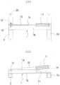
본 발명은 도1 및 도2와 같이 금속판재를 절곡하여서 세로 지지대(1a)와 가로 지지대(1b)를 한 몸통으로 하고, 상기 세로 지지대(1a)의 선단에는 가동날 조립공(1c)을, 후방 일지점에는 가동날 손잡이 받침턱(1d)과, 힘살부(1e)를 형성한 받침날(1)과, 상기 받침날(1)의 가로 지지대(1b)의 전후 선단에는 받침대(2)(2a)를 대각되도록 배치하고 접촉부분을 용착시켜서 받침날(1)과 받침대(2)(2a)가 일체형으로 구성된다.1 and 2, a metal plate is folded to form a
상기 도면에서 미설명된 부호 10은 가동날, 11은 가동날 작동 손잡이, 12는 힌지 볼트, 13은 결속 너트, 20은 통공, 21은 완충부싱을 표시한 것이다.
상기와 같은 본 발명의 작두 본체는 구조가 간단하여 제조가 용이하고, 또 받침날의 가로 지지대 후방 길이를 세로 지지대보다 길게 한 전후에는 받침대를 대각으로 위치시켜 용착하므로서 작두 본체는 견고하게 되고, 세로 지지대에 가동날을 위치시켜서 선단 지점의 조립공에서 힌지볼트와 결속너트로 조립하게 되면 가동날의 손잡이 부위는 힘살부 사이의 공간에 위치되어 안정감을 갖게 되고, 또 가동날의 손잡이는 가동날 받침턱 위에 얹혀지고, 가동날은 세로 지지대에 접촉을 유도하여 가동날이 세로 지지대에서 외측으로 밀려나가지 않아 사용이 편리한 이점이 있다.The main body of the present invention has a simple structure and is easy to manufacture. When the rear length of the support frame of the support blade is longer than that of the vertical support, When the movable blade is positioned on the support and assembled with the hinge bolt and the binding nut in the assembling hole at the end point, the handle portion of the movable blade is positioned in the space between the forceps portions to provide a sense of stability, and the handle of the movable blade, And the movable blade is brought into contact with the vertical support so that the movable blade is not pushed outwardly from the vertical support.
도1은 본 발명의 사시도
도2는 본 발명의 작두 본체에 가동날의 조립 예시도
도3은 본 발명의 작두 본체에 가동날이 조립된 사시도
도4는 본 발명의 작두 본체에 가동날을 조립한 작두이고,
(가)도는 평면도
(나)도는 정면도
도5는 본 발명의 작두 본체에 사용하는 가동날의 조립 예시도
도6 작두의 가동날에 사용하는 손잡이의 사시도BRIEF DESCRIPTION OF THE DRAWINGS FIG.
Fig. 2 is an assembling example of the movable blade in the main body of Fig.
Fig. 3 is a perspective view of the movable body of the present invention,
Fig. 4 is a perspective view showing a movable blade assembled to the main body of Fig.
(A) Turning plan
(B) Turning front view
Fig. 5 is an assembly example of a movable blade used in the main body of Fig.
Fig. 6 is a perspective view of the handle used for the movable blade of Fig.
상기 본 발명의 구체적인 실시 예를 첨부 도면에 의거 설명하면 다음과 같다.DETAILED DESCRIPTION OF THE PREFERRED EMBODIMENTS Hereinafter, preferred embodiments of the present invention will be described with reference to the accompanying drawings.
도1 및 도2와 같이 금속판재를 절곡하여서 세로 지지대(1a)와 가로 지지대(1b)를 한 몸통으로 하고, 상기 세로 지지대(1a)의 선단에는 가동날 조립공(1c)을, 후방 일지점에는 가동날 손잡이 받침턱(1d)과 힘살부(1e)를 형성한 받침날(1)을 구비하며, 상기 받침날(1)의 가로 지지대(1b) 전후 선단에는 받침대(2)(2a)를 대각으로 배치하고 접촉 부분을 용착하여서 받침날(1)과 받침대(2)(2a)가 일체형인 작두 본체가 구성된다.1 and 2, the metal plate is folded so that the
상기 받침날(1)의 가로 지지대(1b)와 받침대(2)(2a)의 접촉부분은 용착하지 않을 경우 볼트와 너트를 이용하여 결속하더라도 무방하다.
상기 받침대(2)(2a)의 전후에는 통공(20)을 더 구비하고 상기 받침대(2)(2a)의 통공(20)을 피스 등으로 바닥면에 작두 본체를 고정 설치할 수 있게 된다.The contact portion between the
A through
상기 본 발명에서 받침날(1)의 세로 지지대(1a) 후방에 가동날의 하강시 하강을 중단하는 가동날 손잡이 받침턱(1d)은 가동날(10)의 받침날(1)에 밀착될 수 있도록 측방으로 경사지게 하고, 또 손잡이 받침턱(1d)에는 고무소재로 된 완충 부싱(21)을 끼우게 되면 가동날(10)의 가동날 작동 손잡이(11)가 하강할 때 가동날 작동 손잡이(11)의 구면 외측지점이 가동날 손잡이 받침턱(1d)에 닿으면 가동날(10)이 받침날(1)과 밀착되면서 완충 된다.In the present invention, the movable
또 상기 가동날 손잡이 받침턱(1d)의 경사지는 범위는 가동날 손잡이 받침턱(1d)의 길이와 가동날 작동 손잡이(11)의 경에 따라 다르게 되나 대략 70˚범위가 안정적이다.The range of inclination of the movable blade
상기 본 발명에서 작두 본체는 금속판재를 절곡하여서 구성하므로 제조가 용이하게 되고, 또 받침날(1)의 세로 지지대(1a) 후방에는 가동날(10)의 가동날 작동 손잡이(11)가 하강할 때 작업자의 손이 닿지 않도록 하는 높이를 짧게 한 힘살부(1e)가 구비되고, 받침날(1) 후방의 받침대(2a)는 가동날(10)의 하강시에 손잡이(11) 후방에 위치되게 구성하므로 작두 본체는 지면에 안전하게 위치되고 사용이 편리하게 된다.The
상기 본 발명의 작두 본체에는 도5 및 도6과 같이 가동날(10)의 후방에 가동날 작동 손잡이(11)를 조립하고, 상기 가동날(10)의 선단을 도2와 같이 작두 본체의 세로 지지대(1a) 선단에 구비한 가동날 조립공(1c)에 위치시켜서 힌지 볼트(12)를 끼우고, 한 쌍의 결속 너트(13)로 결속하게 되면 도3 및 도4의 (가) 및 (나)와 같은 작두가 완성된다.5 and 6, the
상기 작두는 가동날(10) 후방에 구비되는 가동날 작동 손잡이(11)를 잡고 위로 올리면 힌지 볼트(12)를 중심으로 작두 본체의 세로 지지대(1a)와는 경사지게 세워지고, 작두 본체의 세로 지지대(1a)와 가동날(10) 사이에 피절단물을 위치시키고, 가동날(10)의 가동날 작동 손잡이(11)를 내리면 피절단물을 자를 수 있게 된다.When the movable
이때 작두 본체는 바닥에 안전하게 설치되므로 안전사고를 줄일 수 있게 되고 사용이 편리하게 된다.At this time, since the main body is installed on the floor safely, safety accidents can be reduced and the use becomes convenient.
1 : 받침날1a : 세로 지지대
1b : 가로 지지대1c : 가동날 조립공
1d : 가동날 손잡이 받침턱1e : 힘살부
2, 2a : 받침대1: Supporting
1b:
1d: movable blade handle support jaw 1e:
2, 2a: pedestal
Claims (1)
Translated fromKoreanPriority Applications (1)
| Application Number | Priority Date | Filing Date | Title |
|---|---|---|---|
| KR1020130059506AKR101531748B1 (en) | 2013-05-27 | 2013-05-27 | The noumenon a straw cutter |
Applications Claiming Priority (1)
| Application Number | Priority Date | Filing Date | Title |
|---|---|---|---|
| KR1020130059506AKR101531748B1 (en) | 2013-05-27 | 2013-05-27 | The noumenon a straw cutter |
Publications (2)
| Publication Number | Publication Date |
|---|---|
| KR20140139198A KR20140139198A (en) | 2014-12-05 |
| KR101531748B1true KR101531748B1 (en) | 2015-06-25 |
Family
ID=52459285
Family Applications (1)
| Application Number | Title | Priority Date | Filing Date |
|---|---|---|---|
| KR1020130059506AActiveKR101531748B1 (en) | 2013-05-27 | 2013-05-27 | The noumenon a straw cutter |
Country Status (1)
| Country | Link |
|---|---|
| KR (1) | KR101531748B1 (en) |
Families Citing this family (1)
| Publication number | Priority date | Publication date | Assignee | Title |
|---|---|---|---|---|
| KR101709382B1 (en)* | 2014-12-10 | 2017-02-22 | 김완영 | Food cutting equipment |
Citations (4)
| Publication number | Priority date | Publication date | Assignee | Title |
|---|---|---|---|---|
| JPH06285787A (en)* | 1992-09-09 | 1994-10-11 | Hokuyou Sangyo Kk | Dust cover cutter |
| JPH0685792U (en)* | 1993-05-26 | 1994-12-13 | 耕一 朝比奈 | Push-cutting cutter |
| KR20000007944U (en)* | 1998-10-13 | 2000-05-06 | 장익삼 | Chinese herbs cutting |
| JP2005219166A (en)* | 2004-02-06 | 2005-08-18 | Kobayashi Kogu Seisakusho:Kk | Press-cut cutter |
- 2013
- 2013-05-27KRKR1020130059506Apatent/KR101531748B1/enactiveActive
Patent Citations (4)
| Publication number | Priority date | Publication date | Assignee | Title |
|---|---|---|---|---|
| JPH06285787A (en)* | 1992-09-09 | 1994-10-11 | Hokuyou Sangyo Kk | Dust cover cutter |
| JPH0685792U (en)* | 1993-05-26 | 1994-12-13 | 耕一 朝比奈 | Push-cutting cutter |
| KR20000007944U (en)* | 1998-10-13 | 2000-05-06 | 장익삼 | Chinese herbs cutting |
| JP2005219166A (en)* | 2004-02-06 | 2005-08-18 | Kobayashi Kogu Seisakusho:Kk | Press-cut cutter |
Also Published As
| Publication number | Publication date |
|---|---|
| KR20140139198A (en) | 2014-12-05 |
Similar Documents
| Publication | Publication Date | Title |
|---|---|---|
| USD917604S1 (en) | Tripod | |
| USD911091S1 (en) | Barbecue grill | |
| USD616289S1 (en) | Furniture protective device | |
| USD857308S1 (en) | Pets ergonomic feeder | |
| US8418704B1 (en) | Power adjustable crutch assembly | |
| US8756734B1 (en) | Pillow device | |
| USD897711S1 (en) | Adjustable chair | |
| KR101531748B1 (en) | The noumenon a straw cutter | |
| CN103240804B (en) | The method of operating of magnetic briquetting cutting machine and magnetic briquetting | |
| US8118281B1 (en) | Tire lifting assembly | |
| KR20130088437A (en) | Slicing apparatus for food material | |
| CN205462529U (en) | Food comminution device | |
| CA2640991A1 (en) | Cutter assembly for building materials having a non-planar profile | |
| CN204734099U (en) | Dining table | |
| CN204546619U (en) | A kind of combination chopper | |
| CN209825677U (en) | Simple tea table | |
| US20070089729A1 (en) | Camping grill apparatus and method | |
| KR101531789B1 (en) | The body straw cutter | |
| CN202128111U (en) | Telescopic leg | |
| CN108481386B (en) | Safety cutter | |
| CN201798314U (en) | Anti-dumping device | |
| CN207803793U (en) | A multi-point support lifting coffee table | |
| TW200628102A (en) | Folding chair | |
| KR20190086074A (en) | A cutter main body with light weight and work structure | |
| USD815208S1 (en) | Configurable toss game |
Legal Events
| Date | Code | Title | Description |
|---|---|---|---|
| A201 | Request for examination | ||
| PA0109 | Patent application | Patent event code:PA01091R01D Comment text:Patent Application Patent event date:20130527 | |
| PA0201 | Request for examination | ||
| E902 | Notification of reason for refusal | ||
| PE0902 | Notice of grounds for rejection | Comment text:Notification of reason for refusal Patent event date:20140730 Patent event code:PE09021S01D | |
| AMND | Amendment | ||
| PG1501 | Laying open of application | ||
| E601 | Decision to refuse application | ||
| PE0601 | Decision on rejection of patent | Patent event date:20150109 Comment text:Decision to Refuse Application Patent event code:PE06012S01D Patent event date:20140730 Comment text:Notification of reason for refusal Patent event code:PE06011S01I | |
| AMND | Amendment | ||
| PX0901 | Re-examination | Patent event code:PX09011S01I Patent event date:20150109 Comment text:Decision to Refuse Application Patent event code:PX09012R01I Patent event date:20140925 Comment text:Amendment to Specification, etc. | |
| E902 | Notification of reason for refusal | ||
| PE0902 | Notice of grounds for rejection | Comment text:Notification of reason for refusal Patent event date:20150302 Patent event code:PE09021S01D | |
| PX0701 | Decision of registration after re-examination | Patent event date:20150617 Comment text:Decision to Grant Registration Patent event code:PX07013S01D Patent event date:20150129 Comment text:Amendment to Specification, etc. Patent event code:PX07012R01I Patent event date:20150109 Comment text:Decision to Refuse Application Patent event code:PX07011S01I Patent event date:20140925 Comment text:Amendment to Specification, etc. Patent event code:PX07012R01I | |
| X701 | Decision to grant (after re-examination) | ||
| GRNT | Written decision to grant | ||
| PR0701 | Registration of establishment | Comment text:Registration of Establishment Patent event date:20150619 Patent event code:PR07011E01D | |
| PR1002 | Payment of registration fee | Payment date:20150619 End annual number:3 Start annual number:1 | |
| PG1601 | Publication of registration | ||
| FPAY | Annual fee payment | Payment date:20180619 Year of fee payment:4 | |
| PR1001 | Payment of annual fee | Payment date:20180619 Start annual number:4 End annual number:4 | |
| FPAY | Annual fee payment | Payment date:20190618 Year of fee payment:5 | |
| PR1001 | Payment of annual fee | Payment date:20190618 Start annual number:5 End annual number:5 | |
| PR1001 | Payment of annual fee | Payment date:20210617 Start annual number:7 End annual number:7 | |
| PR1001 | Payment of annual fee | Payment date:20220620 Start annual number:8 End annual number:8 | |
| PR1001 | Payment of annual fee | Payment date:20240618 Start annual number:10 End annual number:10 |