KR101530168B1 - Biological assay sample analyzer - Google Patents
Biological assay sample analyzerDownload PDFInfo
- Publication number
- KR101530168B1 KR101530168B1KR1020147032990AKR20147032990AKR101530168B1KR 101530168 B1KR101530168 B1KR 101530168B1KR 1020147032990 AKR1020147032990 AKR 1020147032990AKR 20147032990 AKR20147032990 AKR 20147032990AKR 101530168 B1KR101530168 B1KR 101530168B1
- Authority
- KR
- South Korea
- Prior art keywords
- sample
- black
- reflector
- black sample
- optical axis
- Prior art date
- Legal status (The legal status is an assumption and is not a legal conclusion. Google has not performed a legal analysis and makes no representation as to the accuracy of the status listed.)
- Expired - Fee Related
Links
Images


Classifications
- G—PHYSICS
- G01—MEASURING; TESTING
- G01N—INVESTIGATING OR ANALYSING MATERIALS BY DETERMINING THEIR CHEMICAL OR PHYSICAL PROPERTIES
- G01N21/00—Investigating or analysing materials by the use of optical means, i.e. using sub-millimetre waves, infrared, visible or ultraviolet light
- G01N21/75—Systems in which material is subjected to a chemical reaction, the progress or the result of the reaction being investigated
- G01N21/76—Chemiluminescence; Bioluminescence
- G—PHYSICS
- G01—MEASURING; TESTING
- G01N—INVESTIGATING OR ANALYSING MATERIALS BY DETERMINING THEIR CHEMICAL OR PHYSICAL PROPERTIES
- G01N21/00—Investigating or analysing materials by the use of optical means, i.e. using sub-millimetre waves, infrared, visible or ultraviolet light
- G01N21/62—Systems in which the material investigated is excited whereby it emits light or causes a change in wavelength of the incident light
- G01N21/63—Systems in which the material investigated is excited whereby it emits light or causes a change in wavelength of the incident light optically excited
- G01N21/64—Fluorescence; Phosphorescence
- G01N21/645—Specially adapted constructive features of fluorimeters
- G01N2021/6463—Optics
- G01N2021/6471—Special filters, filter wheel
- G—PHYSICS
- G01—MEASURING; TESTING
- G01N—INVESTIGATING OR ANALYSING MATERIALS BY DETERMINING THEIR CHEMICAL OR PHYSICAL PROPERTIES
- G01N21/00—Investigating or analysing materials by the use of optical means, i.e. using sub-millimetre waves, infrared, visible or ultraviolet light
- G01N21/62—Systems in which the material investigated is excited whereby it emits light or causes a change in wavelength of the incident light
- G01N21/63—Systems in which the material investigated is excited whereby it emits light or causes a change in wavelength of the incident light optically excited
- G01N21/64—Fluorescence; Phosphorescence
- G01N21/645—Specially adapted constructive features of fluorimeters
- G01N2021/6463—Optics
- G01N2021/6473—In-line geometry
- G01N2021/6476—Front end, i.e. backscatter, geometry
- G—PHYSICS
- G01—MEASURING; TESTING
- G01N—INVESTIGATING OR ANALYSING MATERIALS BY DETERMINING THEIR CHEMICAL OR PHYSICAL PROPERTIES
- G01N2201/00—Features of devices classified in G01N21/00
- G01N2201/02—Mechanical
- G01N2201/024—Modular construction
- G01N2201/0245—Modular construction with insertable-removable part
- G—PHYSICS
- G01—MEASURING; TESTING
- G01N—INVESTIGATING OR ANALYSING MATERIALS BY DETERMINING THEIR CHEMICAL OR PHYSICAL PROPERTIES
- G01N2201/00—Features of devices classified in G01N21/00
- G01N2201/06—Illumination; Optics
- G01N2201/063—Illuminating optical parts
- G01N2201/0634—Diffuse illumination
- G—PHYSICS
- G01—MEASURING; TESTING
- G01N—INVESTIGATING OR ANALYSING MATERIALS BY DETERMINING THEIR CHEMICAL OR PHYSICAL PROPERTIES
- G01N2201/00—Features of devices classified in G01N21/00
- G01N2201/06—Illumination; Optics
- G01N2201/063—Illuminating optical parts
- G01N2201/0636—Reflectors
- G—PHYSICS
- G01—MEASURING; TESTING
- G01N—INVESTIGATING OR ANALYSING MATERIALS BY DETERMINING THEIR CHEMICAL OR PHYSICAL PROPERTIES
- G01N2201/00—Features of devices classified in G01N21/00
- G01N2201/06—Illumination; Optics
- G01N2201/066—Modifiable path; multiple paths in one sample
- G01N2201/0666—Selectable paths; insertable multiple sources
Landscapes
- Chemical & Material Sciences (AREA)
- Physics & Mathematics (AREA)
- Health & Medical Sciences (AREA)
- General Physics & Mathematics (AREA)
- Life Sciences & Earth Sciences (AREA)
- Analytical Chemistry (AREA)
- Biochemistry (AREA)
- General Health & Medical Sciences (AREA)
- Immunology (AREA)
- Pathology (AREA)
- Engineering & Computer Science (AREA)
- Chemical Kinetics & Catalysis (AREA)
- Plasma & Fusion (AREA)
- Nuclear Medicine, Radiotherapy & Molecular Imaging (AREA)
- Investigating, Analyzing Materials By Fluorescence Or Luminescence (AREA)
- Investigating Or Analysing Materials By The Use Of Chemical Reactions (AREA)
Abstract
Translated fromKorean
Description
Translated fromKorean관련 출원에 대한 교차 참조
2012년 4월 23일자로 출원된, 미국 가출원 일련번호 제 61/636,860호의 전체가 인용에 의해 본원에 명백하게 포함된다.
Cross-reference to related application
U.S. Provisional Serial No. 61 / 636,860, filed April 23, 2012, is expressly incorporated herein by reference in its entirety.
본원에 개시되고 청구되는 본 발명의 개념들은 샘플(sample) 분석기에 관한 것이며, 보다 구체적으로는, 이것으로 제한하는 것은 아니지만, 발광 검정 샘플(luminescent assay sample)로부터의 광자(photon) 수집 효율을 개선하기 위해 반사기를 갖는 샘플 분석기들에 관한 것이다.
The concepts of the present invention as disclosed and claimed herein relate to a sample analyzer, and more particularly, but not by way of limitation, improved photon collection efficiency from a luminescent assay sample ≪ / RTI > to a sample analyzer having a reflector.
화학 발광은 화학 반응의 결과로서의 광의 방출이다. 발광을 이용하는 다양한 타입들의 화학 분석들이 개발되어왔고, 형광 화합물들 및 화학 발광 화합물들과 같은 발광 화합물들이 핵산 검정 및 면역 검정과 같은 검정에서 라벨(label)들로서 사용되어왔다. 발광 측정들을 이용하는 다양한 타입들의 계기가 제약 및 의학 산업들에서 많이 이용된다. 분석 측정들은 종종 특정 샘플-시약(sample-reagent) 조합과 상호작용하기 위해 촉매 복사 빔(beam)을 사용하여 수행된다. 종종 매우 약한, 결과적인 광자 방출은 그 후 감지 검출기(sensitive detector)에 의해 검출되고 측정되며, 전기 신호로 변환되고, 실제 분석 결과를 제공하기 위해 추가로 상호 관계된다.
Chemiluminescence is the emission of light as a result of a chemical reaction. Various types of chemical assays using luminescence have been developed and luminescent compounds such as fluorescent compounds and chemiluminescent compounds have been used as labels in assays such as nucleic acid assays and immunoassays. Various types of instruments that utilize luminescence measurements are commonly used in the pharmaceutical and medical industries. Analytical measurements are often performed using a catalytic radiation beam to interact with a particular sample-reagent combination. The resultant photon emissions, which are often very weak, are then detected and measured by a sensitive detector, converted into electrical signals, and further correlated to provide an actual analysis result.
예컨대, 미국 특허 제 5,709,994호는 발광 산소 채널링 면역 검정(LOCI; Luminescent Oxygen Channeling Immunoassay))으로서 공지된 매우 민감한 검정 방법을 개시한다. 이 방법은 조사(irradiation)시에 일중항 산소(singlet oxygen)를 발생하는 광민감제(photosensitizer), 그리고 일중항 산소에 의해 활성화되는 화학 발광 화합물을 사용한다. 광민감제 및 화학 발광 화합물은 특정 파장의 광에 의해 조사되고, 그 후에 화학 발광 화합물에 의해 방출되는 결과적인 광이 검정을 제공하기 위해 측정되고 상호 관계된다.
For example, U.S. Patent No. 5,709,994 discloses a highly sensitive assay method known as Luminescent Oxygen Channeling Immunoassay (LOCI). This method uses a photosensitizer that generates singlet oxygen during irradiation, and a chemiluminescent compound that is activated by singlet oxygen. The photosensitizer and the chemiluminescent compound are irradiated by light of a particular wavelength, and then the resultant light emitted by the chemiluminescent compound is measured and correlated to provide assay.
이러한 분석들, 또는 검정들은 통상적으로 환자 샘플들을 담고 있는 바이알(vial)들이 그 안으로 로딩되는 자동화된 분석기들을 수반한다. 개선된 샘플 컨테이너들이 새로운 약물 개발을 위한 고 처리량 스크리닝(high-throughput screening)을 위해서 개발되어왔다. 방법들 및 계기들의 계속되는 개선들은 현저하게 증가한 검정 처리량 및 증가하는 속도를 초래하였다.
These assays, or assays, typically involve automated analyzers into which vials containing patient samples are loaded. Improved sample containers have been developed for high-throughput screening for new drug development. Continued improvements in methods and instruments have resulted in significantly increased black throughput and increased speed.
발광을 기반으로 하는 검정을 위해 이용되는 계기는, 부분적으로는, 사용되는 복잡하고 민감한 광학계(optics)로 인해 종종 물리적으로 대형이다. 크기(size)는 고 처리량 스크리닝을 용이하게 하는 대형 실험실들에서 주요 관심사가 아니지만; 발광을 기본으로 하는 정확한 분석들을 발생할 수 있는 더 경량의, 휴대용 유닛 또는 핸드헬드(handheld) 기기를 갖는 것이 유용할 것이다. 특히 로우 라이트(low light) 광자 카운팅 분야들에서, 전력 요건들을 감소시키고, 필요한 광 경로를 감소시키고, 광자 수집 효율을 증가시키는 디자인들이 이러한 휴대용 유닛을 제공하는 것을 도울 것이다.
Instruments used for emission-based assays are often physically large, in part due to the complex and sensitive optics used. Size is not a major concern in large laboratories that facilitate high throughput screening; It would be useful to have a lighter, portable unit or handheld device capable of producing accurate assays based on light emission. In low light photon counting applications in particular, designs that reduce power requirements, reduce the required light path, and increase photon collection efficiency will help provide such a portable unit.
전술한 관점에서, 감소된 샘플 크기, 감소된 전력 요구사항들, 감소된 광 경로 및 광자 수집 효율을 증가시키는 발광계 샘플 분석기에 대한 요구가 있다. 현재 개시되고 청구되는 본 발명의 개념(들)이 지향하는 것은 이러한 발광 샘플 분석기이다.
In view of the foregoing, there is a need for an emitter sample analyzer that increases the reduced sample size, reduced power requirements, reduced optical path, and photon collection efficiency. It is this luminescence sample analyzer that the presently claimed and claimed concept (s) of the present invention is directed to.
본원에 개시되고 청구되는 본 발명의 개념들은 일반적으로 발광을 이용하는 샘플 분석기에 관한 것이다. 이 샘플 분석기는 발광을 야기하기 위해 검정 샘플을 조명하기 위한 조명 장치(illuminator), 그리고 검정 샘플을 담고 있는 샘플 용기를 위한 지지부를 갖는다. 지지부는 검정 샘플을 조명 장치에 근접하게 위치시키도록 적응된다. 발광을 검출하기 위한 검출기가 조명 장치로부터, 위치된 검정 샘플을 통하여 검출기로 연장하는 광축(optical axis)을 따라 위치된다. 반사기가 조명 장치와 위치된 검정 샘플 사이에서 제거 가능하게 배치되어, 발광의 일부를 위치된 검정 샘플을 통하여 검출기를 향해 다시 반사한다.
The concepts of the present invention as disclosed and claimed herein generally relate to a sample analyzer utilizing luminescence. The sample analyzer has an illuminator for illuminating the black sample to cause luminescence, and a support for the sample container containing the black sample. The support is adapted to position the black sample proximate the illuminator. A detector for detecting the light emission is located from the illumination device along an optical axis extending from the positioned black sample to the detector. A reflector is removably disposed between the illumination device and the positioned black sample so that a portion of the light is reflected back toward the detector through the located black sample.
일 실시예에서, 반사기는 셔틀(shuttle)에 배치된다. 샘플 분석기는 분석의 측정 모드 동안 반사기를 광축과, 그리고 직각으로 그리고 위치된 샘플에 인접하게 정렬하도록 구성되는 셔틀 제어기를 포함한다. 셔틀은 그 후 조명 모드 동안 반사기를 광축으로부터 멀리 이동시킨다.
In one embodiment, the reflector is disposed in a shuttle. The sample analyzer includes a shuttle controller configured to align the reflector with the optical axis during the measurement mode of analysis and at a right angle and adjacent to the positioned sample. The shuttle then moves the reflector away from the optical axis during the illumination mode.
일부 실시예들에서, 검출기는 위치된 샘플로부터 3 내지 15㎜ 사이에 위치된다.
In some embodiments, the detector is positioned between 3 and 15 mm from the positioned sample.
다른 실시예에서, 샘플 분석기는 조명 장치와 셔틀 사이에 위치되는 광 확산기(light diffuser)를 포함한다. 광 확산기는 광축과 그리고 직각으로 정렬되며, 조명 모드에서 조명 장치로부터 위치된 샘플로 광을 확산시킨다. 또 다른 실시예에서, 광 확산기는 셔틀에 위치된다.
In another embodiment, the sample analyzer includes a light diffuser positioned between the illuminator and the shuttle. The light diffuser is aligned with the optical axis and at right angles, and diffuses the light from the illuminator to the sample located in the illumination mode. In another embodiment, the light diffuser is located in the shuttle.
검정 샘플로서 분석하는 방법은 이하의 단계들을 포함한다. 샘플 분석기가 얻어지는 단계로서, 이 샘플 분석기는 조명 장치, 이 조명 장치에 근접한 검정 샘플을 담고 있는 샘플 용기를 지지하기 위해 위치되는 지지부, 조명 장치로부터, 검정 샘플을 통하여 검출기로 연장하는 광축을 따라 위치되는 검출기, 그리고 조명 장치와 검정 샘플 사이에 제거 가능하게 배치되는 반사기를 포함한다. 검정 샘플을 담고 있는 샘플 용기는 조명 장치에 근접하여 지지된다. 검정 샘플은 발광을 야기하기 위해 조명된다. 반사기는 발광의 일부를 검정 샘플을 통하여 검출기를 향하여 다시 반사하기 위해 조명 장치와 검정 샘플 사이에 위치된다. 검출기는 그 후 발광을 측정한다.
The method of analyzing as a black sample comprises the following steps. A sample analyzer is provided comprising: a light source; a support positioned to support a sample container containing a black sample proximate to the illumination device; a light source positioned along the optical axis extending from the illumination device through the black sample to the detector; And a reflector that is removably disposed between the illuminator and the calibration sample. The sample container containing the black sample is supported close to the illuminator. The black sample is illuminated to cause luminescence. The reflector is positioned between the illuminator and the black sample to reflect back a portion of the emission through the black sample towards the detector. The detector then measures the luminescence.
도면들 내의 동일한 참조 부호들은 동일한 또는 유사한 요소 또는 기능을 나타내고 지칭한다. 본 개시의 이행들은 이후의 본 개시의 상세한 설명이 고려될 때 더 양호하게 이해될 수 있다. 이러한 설명은 병합된 그림을 포함하는 예시들, 개략도들, 그래프들 및 도면들을 참조한다. 도면들은 반드시 실척은 아니며 도면들의 특정 피쳐들 및 특정 도들은 명료함 및 간결함을 위해 확대되어, 실척대로 또는 개략적으로 도시될 수 있다.
The same reference numbers in the drawings denote the same or similar elements or functions and refer to them. The implementation of the present disclosure may be better understood when the following detailed description of the present disclosure is taken into consideration. This description refers to examples, schematic diagrams, graphs and drawings that include a merged figure. The drawings are not necessarily exhaustive and the specific features and specificities of the figures may be exaggerated for clarity and brevity and may be shown to scale or schematic.
도 1은 본원에 개시된 본 발명의 개념들에 따라 구성된 샘플 분석기의 실시예의 개략도이다.
도 2는 본원에 개시된 본 발명의 개념들에 따라 구성된 미세유체 카드 샘플(microfluidic card sample) 용기의 실시예의 개략도이다.
도 3a는 디스크 형상 샘플 저장소의 발광 샘플에 의해 방출되는 광의 모델이다.
도 3b는 일 측에 인접하여 반사기를 갖는 디스크 형상 샘플 저장소의 발광 샘플에 의해 방출되는 광의 모델이다.
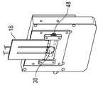
도 4a는 본원에 개시된 본 발명의 개념들에 따라 구성된 반사기 및 셔틀을 갖는 샘플 분석기의 실시예의 개략도이다.
도 4b는 반사기(48)를 예시하는 도 4a에 도시된 실시예의 다른 도면이다.
도 4c는 광축(24)에 정렬된 검정 용기(30)를 예시하는 도 4a에 도시된 실시예의 또 다른 도면이다.
도 5a는 조명 장치 측으로부터 본 도 4의 셔틀을 묘사한다.
도 5b는 샘플 용기 측으로부터 본 도 4의 셔틀을 묘사한다.
도 6은 본원에 개시된 본 발명의 개념들에 따른 샘플 분석기 작업의 실시예를 위한 타이밍 다이어그램(timing diagram)이다.
도 7은 상업적인 VISTA® LOCI 판독기와의 양호한 상호 관계를 묘사하는 프로토타입 판독기(prototype reader)로부터의 광자 카운트들의 그래프이다.
도 8은 상업적인 VISTA® LOCI 판독기와 비교되고 반사기에 의해 개선된 성능을 나타내는 본 발명의 일 실시예에 따른 프로토타입 판독기로부터의 광자 카운트들의 그래프이다.1 is a schematic diagram of an embodiment of a sample analyzer constructed in accordance with the concepts of the present invention disclosed herein.
2 is a schematic diagram of an embodiment of a microfluidic card sample container constructed in accordance with the concepts of the present invention disclosed herein.
Figure 3a is a model of light emitted by a luminescent sample in a disc shaped sample reservoir.
3B is a model of light emitted by a luminescent sample of a disc shaped sample reservoir having a reflector adjacent to one side.
4A is a schematic diagram of an embodiment of a sample analyzer having a reflector and shuttle configured in accordance with the concepts of the present invention disclosed herein.
4B is another view of the embodiment shown in FIG. 4A illustrating the
FIG. 4C is another view of the embodiment shown in FIG. 4A illustrating a
Figure 5a depicts the shuttle of Figure 4 as viewed from the illuminator side.
Figure 5b depicts the shuttle of Figure 4 viewed from the sample vessel side.
Figure 6 is a timing diagram for an embodiment of a sample analyzer operation in accordance with the concepts of the present invention disclosed herein.
Figure 7 is a graph of photon counts from a prototype reader depicting a good correlation with a commercial VISTA (R) LOCI reader.
8 is a graph of photon counts from a prototype reader according to one embodiment of the present invention compared to a commercial VISTA LOCI reader and showing improved performance by a reflector.
본원에 개시된 본 발명의 개념의 하나 이상의 실시예를 자세하게 설명하기 전에, 본 발명의 개념은 이후의 설명에 명시되는 또는 도면들에 예시된 구성요소들의 구성, 실험들, 예시적인 데이터 및/또는 배열의 세부사항들로 본 출원에서 제한되지 않는 것이 이해되어야 한다. 현재 개시된 그리고 청구되는 본 발명의 개념은 다른 실시예들일 수 있거나 다양한 방식들로 시행되고 실행될 수 있다. 또한, 본원에 이용된 어법 및 기술 용어는 단지 설명의 목적을 위한 것이며 어떠한 방식으로도 제한으로서 간주되어서는 안되는 것이 이해되어야 한다.
Before describing in more detail one or more embodiments of the inventive concepts disclosed herein, the concepts of the present invention may be embodied in the form of structures, experiments, exemplary data and / or arrangements of elements It is to be understood that the invention is not limited in its application to the details of this disclosure. The concepts of the presently disclosed and claimed invention may be embodied in other forms, or may be embodied and carried out in various ways. It is also to be understood that the phraseology and technical terminology used herein is for the purpose of description and should not be regarded as limiting in any manner.
본 발명의 개념의 실시예들의 이후의 상세한 설명에서, 수많은 특정 세부사항들이 본 발명의 개념의 더 온전한 이해를 제공하기 위해 명시된다. 하지만, 당업자에게 본 개시 내의 본 발명의 개념이 이러한 특정 세부사항들 없이 시행될 수 있는 것이 자명할 것이다. 다른 예들에서, 주지된 피쳐들은 지금의 개시를 불필요하게 복잡하게 하는 것을 피하기 위해 상세하게 설명되지 않았다.
In the following detailed description of embodiments of the inventive concepts, numerous specific details are set forth in order to provide a thorough understanding of the concepts of the present invention. However, it will be apparent to one skilled in the art that the concept of the present invention in this disclosure can be practiced without these specific details. In other instances, well-known features have not been described in detail in order to avoid unnecessarily complicating the present disclosure.
또한, 대조적으로 명백하게 언급되지 않는 한, "또는(or)"은 포괄적인 "또는"을 지칭하고 배타적인 "또는"을 지칭하지 않는다. 예컨대, 조건 A 또는 B는 이후의 조건 : A가 참(또는 존재) 그리고 B가 거짓(또는 존재하지 않음), A가 거짓(또는 존재하지 않음) 그리고 B가 참(또는 존재), 그리고 A와 B 모두가 참(또는 존재)인 조건 중 어느 것에 의해서도 만족된다.
Also, unless the context clearly indicates otherwise, the word "or" does not refer to a generic term or "exclusive" or " For example, a condition A or B can be defined as follows: A is true (or exists) and B is false (or nonexistent), A is false (or nonexistent) B are both true (or present).
게다가, 관사("a" 또는 "an")의 사용은 본원의 실시예들의 요소들 및 구성요소들을 설명하기 위해 이용된다. 이는 단지 편의를 한 것이며 본 발명의 개념의 일반적인 의미를 부여한다. 이러한 설명은 하나 또는 하나 이상을 포함하는 것으로 읽혀야 하며 단수는 또한 이 단수가 달리 의미를 갖는 것이 명백하지 않는다면 복수를 포함한다.
Moreover, the use of articles ("a" or "an") is used to describe the elements and components of the embodiments of the present disclosure. This is merely a convenience and gives the general meaning of the concept of the present invention. This description should be read to include one or more than one, and the singular also includes the plural unless it is obvious that the singular has different meanings.
발광 산소 채널링 면역 검정(LOCI) 방법들 및 광학 시스템들에 대한 참조는 단지 예를 위한 것이고, 본 발명의 개념들은 발광 검출을 이용하는 임의의 샘플 분석 과정과 함께 사용될 수 있다. "샘플" 또는 "검정 샘플"에 대한 참조는 분석될 샘플을 지칭하고 분석 과정에 따라 첨가되는 시약들을 포함하며, 이러한 시약들은 검정 샘플 용기 안으로의 삽입 이전 또는 후에 첨가된다.
References to luminescent oxygen channeling immunoassay (LOCI) methods and optical systems are for example only, and the concepts of the present invention may be used with any sample analysis procedure that uses luminescence detection. A reference to "sample" or "black sample" refers to the sample to be analyzed and includes reagents added according to the analysis procedure, and these reagents are added before or after insertion into the black sample container.
마지막으로, 본원에 사용되는 것과 같은 "일 실시예" 또는 "실시예"에 대한 임의의 참조는 실시예와 관련하여 설명된 특정 요소, 피쳐, 구조 또는 특징이 하나 이상의 실시예에 포함되는 것을 의미한다. 명세서의 다양한 부분들에서의 "일 실시예에서"라는 어구의 등장은 반드시 모두 동일한 실시예를 참조하는 것은 아니다.
Finally, any reference to "one embodiment" or "an embodiment ", as used herein, means that a particular element, feature, structure, or characteristic described in connection with the embodiment is included in one or more embodiments do. The appearances of the phrase "in one embodiment" in various portions of the specification are not necessarily all referring to the same embodiment.
화학 발광을 이용하는 기술들이 약물 분석(drug analysis)으로부터 토양 분석(soil analysis) 및 푸드 케미스트리(food chemistry)에 이르는 분야들에서 매우 다양한 분석물들 및 샘플들을 검출하는데 사용되어왔다. 액상 화학 발광 분석들은 효소 검정 및 탄수화물, 뉴클레오티드(nucleotide), 스테로이드(steroid) 및 다양한 약물들을 위한 검정을 포함한다. 미국 특허 제 7,402,281호에서 논의된 것과 같이, 환자 진단 및 치료에 연관된 다양한 타입들의 분석 시험들이 환자의 감염부들, 체액 또는 종기로부터 취해진 액체 샘플의 분석에 의해 수행될 수 있다. 체액의 예들은 요(urine), 전혈, 혈청, 혈장, 타액, 뇌척수액, 비인두 표본, 질근 표본들, 정액, 눈물, 조직(세포 재료들) 등을 포함한다.
Techniques using chemiluminescence have been used to detect a wide variety of analytes and samples in areas ranging from drug analysis to soil analysis and food chemistry. Liquid chemiluminescent assays include enzyme assays and assays for carbohydrates, nucleotides, steroids and various drugs. As discussed in U.S. Patent No. 7,402,281, various types of analytical tests related to patient diagnosis and treatment can be performed by analysis of a liquid sample taken from the infected parts, fluids, or boils of the patient. Examples of body fluids include urine, whole blood, serum, plasma, saliva, cerebrospinal fluid, nasopharyngeal specimens, gallbladder specimens, semen, tears, tissues (cell materials), and the like.
"면역 검정"은 결합(binding) 및 화학 반응에서 항원 또는 항체로서 작용하는 그 능력을 기본으로 하여, 호르몬 또는 효소와 같은 분석물의 존재 또는 농도를 측정한다. 화학 발광 면역 검정은, 보통 산화 환원 반응으로부터 나오는 화학 에너지에 의해 여기될 때(excited) 광을 발생하는 화학 발광 라벨을 이용한다. 화학 발광 분자들은 항원들에 직접 활용될 수 있거나, 또는 이들이 효소 라벨들을 위한 기질들로서 사용될 수 있다. 공통적으로 사용되는 화학 발광 라벨들은 아크리디늄 에스테르들, 루미놀들 및 디옥세탄들을 포함한다.
"Immunoassay" measures the presence or concentration of an analyte, such as a hormone or enzyme, based on its ability to act as an antigen or antibody in binding and chemical reactions. Chemiluminescent immunoassays use chemiluminescent labels that generate light when excited by chemical energy usually coming from a redox reaction. Chemiluminescent molecules can be used directly in antigens, or they can be used as substrates for enzyme labels. Commonly used chemiluminescent labels include acridinium esters, luminol and dioxetanes.
LOCI 기술은 플라즈마의 매우 작은 샘플들을 검정하는데 사용될 수 있고 2개의 상이한 코팅된 합성 입자들 또는 비드들의 근접성, 광증감제를 함유하는 증감제 비드(센시-비드(sensi-bead)), 및 화학 발광제를 함유하는 화학 발광제 비드(화학-비드)를 기반으로 한다. 하나의 LOCI 과정에서, 스트렙타비딘(streptavidin)이 증감제 비드의 표면에 결합되며, 일중항 산소를 발생하기 위해 680㎚에서 광을 흡수하는 프탈시아닌을 함유한다. 이는 여기(excitation)를 위해 상업적으로 이용 가능한 680㎚ 고체 상태 레이저 또는 다이오드들을 사용하는 것을 허용한다. 화학 발광제 비드는 분석물 특정 항체에 의해 코팅된다. 샘플의 분석물은 화학 발광제 비드의 분석물 특정 항체에 결합하고 또한 바이오티닐레이티드(biotinylated) 수용체 항원에 결합한다. 스트렙타비딘을 갖는 광증감제 비드는 바이오티닐형 수용체 항원 : 분석물 : 분석물 특정 항체 : 화학 발광제 복합체(complex)에 결합하며 따라서 입자 이량체(dimer)의 형성, 즉 화학 발광제 비드와 링크 결합되는 증감제 비드를 야기한다. 화학 발광제 비드는 일중항 산소와 반응하는 올레핀 염료(티옥센)를 함유하며, 390㎚에서 광을 방출한다(화학 발광). 일중항 산소의 짧은 반감기는 증감제 비드가 화학 발광을 발생하기 위해 화학 발광제 비드와 매우 근접한 상태에 있어야만 하는 것을 보장한다. 따라서, 입자 이량체의 생성은 화학 발광 신호를 발생하는 것을 허용하지만, 연관되지 않은 입자들이 발광 신호들을 생성하지 못할 수 있다. 형광 에너지 수용체(acceptor)(유로피윰 킬레이트(Europium Chelate))는 방출 파장을 즉시 612㎚로 이동시키고, 결과적인 광 방출은 입자 쌍들 또는 이량체들의 양과 직접 상호 관계되어, 샘플의 분석물의 농도의 정량화를 허용한다.
The LOCI technique can be used to test very small samples of plasma and includes the proximity of two different coated synthetic particles or beads, sensitiser beads containing a photosensitizer (sensi-bead), and chemiluminescent Based chemiluminescent beads (chemical-beads). In one LOCI process, streptavidin binds to the surface of the sensitizer beads and contains phthalocyanine that absorbs light at 680 nm to generate singlet oxygen. This allows the use of commercially available 680 nm solid state lasers or diodes for excitation. Chemiluminescent beads are coated by analyte specific antibodies. The analyte of the sample binds to the analyte specific antibody of the chemiluminescent bead and also binds to biotinylated receptor antigens. A photosensitizer bead having streptavidin binds to a biotinyl-type receptor antigen: analyte: analyte-specific antibody: chemiluminescent complex and thus forms a particle dimer, that is, a chemiluminescent bead Link causes the additive bead to be combined. Chemiluminescent beads contain olefinic dyes (thioxenes) that react with singlet oxygen and emit light at 390 nm (chemiluminescence). The short half-life of singlet oxygen ensures that the sensitiser beads must be in close proximity to the chemiluminescent bead to generate chemiluminescence. Thus, the generation of the particle dimer allows the generation of the chemiluminescent signal, but the unassociated particles may not produce the emission signals. The fluorescence energy acceptor (Europium Chelate) immediately shifts the emission wavelength to 612 nm and the resulting light emission is directly correlated with the amount of the particle pairs or dimers to quantify the concentration of the analyte in the sample .
이제 도면들을 참조하면, 그리고 더 특별하게는 도 1을 참조하면, 본원에 개시되고 청구된 본 발명의 개념들에 따라 구성된 샘플 분석기(10)의 예시적인 실시예가 여기에 도시된다. 샘플 분석기(10)는 발광을 야기하기 위해 검정 샘플(14)을 조명하기 위한 조명 장치(12)를 포함한다. 지지부(16)는 검정 샘플(14)이 조명 장치(12)에 근접하게 위치되도록 검정 샘플(14)을 담고 있는 샘플 용기(18)를 위치시킨다. 반사기(20)가 조명 장치(12)와 위치된 검정 샘플(14) 사이에 제거 가능하게 배치된다. 발광을 검출하기 위한 검출기(22)가 조명 장치(12)로부터, 위치된 검정 샘플(14)을 통하여, 검출기(22)로 연장하는 광축(24)을 따라 위치된다. 샘플 분석기(10)는 선택적으로는 셔터(26) 및 필터(28)를 포함한다. 셔터(26)는 검정의 조명 페이스 동안 광전자 증배관(photomultiplier tube)(PMT)들과 같은 고감도 검출기들을 조명 장치(12)로부터 보호하는데 사용된다. 필터(28)는 검출기(22)로의 광의 특정 파장들을 필터링하는데 사용될 수 있다.
Referring now to the drawings, and more particularly with reference to Figure 1, an exemplary embodiment of a
이후에 더 상세하게 논의되는 것과 같이, 기본 샘플 분석 프로세스는 검정 샘플 용기 안으로 검정될 액체를 삽입하는 단계; 샘플이 발광하는 것을 야기하기 위해 검정 샘플을 조사하는 단계(때때로, 이후에 "조명"이라고 지칭함); 조사 또는 조명의 결과로서 샘플에 의해 방출되는 광을 검출하는 단계; 및 검정에 대한 검출된 광의 양을 상호 관계하는 단계를 포함한다. 다양한 타입들 및 구성들의 검정 샘플 용기(18)들이 사용될 수 있다. 일 실시예에서, 검정 샘플 용기(18)는 디스크 형상 샘플 저장소(30)를 갖는 미세 유체 "카드"이다. 이러한 미세 유체 카드들은 당업자에게 공지되어 있다.
As will be discussed in further detail below, the basic sample analysis process includes the steps of inserting a liquid to be assayed into a black sample vessel; (Sometimes referred to hereinafter as "illumination") of irradiating a black sample to cause the sample to emit light; Detecting light emitted by the sample as a result of illumination or illumination; And correlating the amount of detected light to the test.
미세 유체 카드의 간소화된 모델이 도 2에 도시된다. 도 2의 모델은 단지 샘플 저장소(30), 유체 이송부(32)들 및 유체 입구(34)들만을 포함한다. 샘플 저장소(30)는 카드의 바닥부를 향하는 원형 또는 디스크 형상의 피쳐로서 도시된다. 검정 샘플(14)은 검정 샘플을 유체 입구(34)들 중 하나 안으로 주입함으로써 유체 이송부(32)들을 통하여 샘플 저장소(30)로 전달될 수 있다. 샘플 저장소(30)의 조명 측(36), 뿐만 아니라 샘플 저장소(30)의 측정 측(38)은 조명 장치(12)로부터의 광 그리고 검정 샘플로부터의 발광 광에 대해 투명하다. 이러한 샘플 용기 디자인은 샘플 저장소(30)의 두께(42)에 대해 큰 직경(40)을 갖는 비교적 얇은 샘플 저장소(30)를 허용한다. 얇은 샘플 저장소는 에지(44)의 표면적에 대하여 조명 면(36) 및 측정 면(38)을 위한 큰 표면적을 각각 제공한다.
A simplified model of the microfluidic card is shown in FIG. The model of FIG. 2 includes
일 실시예에서, 검정 샘플(14)은 약 50㎜ 내지 약 120㎜ 길이, 약 30㎜ 내지 약 75㎜ 너비, 그리고 약 2㎜ 내지 약 3㎜ 두께의 미세 유체 카드에 담겨진다. 끼워진(embeded) 원형 또는 디스크 형상 샘플 저장소(30)는 약 7㎜ 내지 10㎜의 직경과 1.5㎜ 내지 2.5㎜의 내측 두께를 갖는다. 이는 약 50 내지 200μL의 샘플 체적을 제공한다. 다른 실시예에서, 샘플 저장소 용적은 50μL미만이다. 카드의 크기는 매우 광범위하게 변할 수 있으며, 샘플 저장소(30)의 형상은 원형 디스크로 제한되지 않으며, 에지(44)의 표면적에 대한 측정 면(38)을 위한 큰 표면적을 제공하는 얇은 샘플 저장소는 에지(44)를 통하는 발광 손실을 감소시키며, 이에 의해 검출기에 도달하는 광 세기를 증가시킨다. 얇은 샘플 저장소는 방사 검정 샘플(14)과 검출기(22) 사이의 광 경로 길이를 단축시키는 것을 또한 돕고, 이에 의해 검출기에 도달하는 광 세기를 증가시킨다. 일 실시예에서, 검출기(22)의 인테이크(intake) 광학계들은 샘플 저장소(30)의 측정 측(38)으로부터 약 2㎜ 내지 15㎜에 위치된다. 다른 실시예에서, 검출기(22)의 인테이크 광학계(46)들은 샘플 저장소(30)의 측정 측(38)으로부터 약 2㎜ 내지 7㎜에 위치된다.
In one embodiment, the black sample 14 is contained in a microfluidic card of about 50 mm to about 120 mm long, about 30 mm to about 75 mm wide, and about 2 mm to about 3 mm thick. The embeded circular or disc shaped
도 3a는 디스크 형상 샘플 저장소(30) 내의 발광 검정 샘플로부터의 광자 방출의 모델링 결과들을 도시한다. 샘플 저장소(30)의 검정 샘플로부터의 광자 방출 패턴은 등방성(isotropic)이다. 동일한 광자들이 검출기(22)를 향하여 나오고 일부는 검출기로부터 멀어지도록 나온다. 결과로서, 검출기 인테이크 광학계들에 입사하지 않는 나오는 광자들은 소산 및 주변 기반 구조의 흡수 효과들에 의해 손실될 수 있고, 반응 관련 광자들이 카운트되지 않는 것을 초래한다.
3A shows modeling results of photon emission from a luminescence assay sample in a disc shaped
도 3b는 샘플 저장소(30)의 일 면에 인접한 반사기(20)를 갖는 디스크 형상 샘플 저장소(30) 내의 발광 검정 샘플로부터의 광자 방출의 모델링 결과들을 도시한다. 검출기(22)로부터 멀어지는 방향으로 검정 샘플로부터 나오는 광자들은 이제 반사기(20)로부터, 다시 검정 샘플(14)을 통하여, 샘플 저장소(30)의 측정 면(38) 밖으로 반사된다. 더 많은 광자들이 검출기(22)를 향하여 지향될수록, 광자 방출의 측정은 현저히 개선된다.
3B shows modeling results of photon emission from a luminescence calibration sample in a disc-shaped
검출기(22)는 특별한 검정에 의해 요구되는 감도를 갖는 임의의 광 검출기일 수 있다. 광전자 증배관(PMT)들과 같은 진공 광 검출기들이 통상적으로 매우 민감성이다. 더 적은 감도가 요구될 때 실리콘 포토 다이오드(silicon photodiode)와 같은 고체 상태 광 검출기들이 종종 사용된다. 이러한 검출기들 및 이들의 사용은 당업자에게 주지되어 있다. 광자 카운팅 전자기기를 사용하는 검출기(22)는 규정된 시간 간격, 통상적으로 약 10초에 걸쳐 검정 샘플(14)로부터의 광 방출을 측정한다. 검정 샘플(14)의 분석물 농도는 검정 샘플 용적 및 광자 발생에 정비례한다. 샘플 분석기 소프트웨어는 광자 카운트로부터 분석물 농도를 산출한다. 제작 동안, 샘플 분석기(10)는 정확한 검정 리포팅을 보증하기 위해 공지된 분석물 농도의 표준들의 세트를 사용하여 교정될 수 있다.
The
일 실시예에서, 샘플 분석기(10)는 그 사이에 위치된 검정 샘플에 대하여 이면 조명(back illumination) 및 전방 검출을 제공하도록 구성된다. 따라서, 반사기(20)는 분석의 촉매 조명 부분 동안 위치의 밖으로 이동되고, 분석의 검출 부분 동안 샘플 저장소(30)의 조명 면(36)에 인접한 위치로 이동된다. 도 4a 내지 도 4c에 예시된 것과 같이, 반사기(20)는 셔틀(48)에 위치되고, 셔틀 액츄에이터 메커니즘(shuttle actuator mechanism)(도시되지 않음)에 의해, 광이 반응 및 광자 방출을 시작하도록 검정 샘플 저장소(30) 안으로 비출 때 조명 간격(interval) 동안 조명 경로의 진로 밖으로 "움직이게 된다(shuttled)". 조명 간격 후에, 검정 샘플(14)은 광자들을 방출함으로써 반응하기 시작하고, 반사기(20)는 검정 샘플 저장소 뒤의 위치로 움직이게 되고, 이에 의해 검출기(22)를 향하여 광자들을 반사한다. 적절한 셔틀 액츄에이터 메커니즘의 비제한적인 예들은 스프링에 대항하여 작동하는 셔틀에 대한 링크 결합을 갖는 배터리 작동식 솔레노이드(solenoid), 스와이프(swipe)를 행하는 회전 토크 모터, 셔틀에 연결되는 랙-앤-피니언 기어 세트(rack-and-pinion gear set)를 구비한 전기 모터, 셔틀과 맞물리는 스테퍼 모터(stepper motor) 등을 포함한다. 일 실시예에서, 셔틀 작동은 셔터(26)의 작동과 통합된다.
In one embodiment, the
도 4a의 이미지는 반사 위치에 있는 반사기(20) 그리고 슬라이딩 가능한 방식으로 셔틀(48)을 또한 지지하는데 사용되는 지지부(16)의 일부를 도시한다. 도 4b의 이미지는 여전히 반사 위치에 있는 반사기(20)를 갖는 더 많은 셔틀(48)을 도시한다. 도 4c의 이미지는 반투명으로서 반사기(20)와 셔틀(48)을 도시하여 샘플 저장소(30)의 실루엣을 볼 수 있다.
The image of Figure 4a shows the
반사기(20)는 편평하거나 곡선일 수 있고 적절한 반사 특성들을 갖는 임의의 재료를 포함할 수 있다. 시험된 2개의 예시적인 반사기들은 상업적으로 이용 가능한 1㎜ 두께의 편평한 거울과 커스텀 파라볼릭 스플라인 반사기(custom parabolic spline reflector)였다. 파라볼릭 반사기는 플라스틱 폼(form) 상에 진공 증착 프로세스를 사용하여 제작될 수 있다. 편평한 거울 반사기에 의한 시험들은 반사기가 없는 측정에 비교하여 신호 이득(signal gain)에서 1.5배의 측정된 개선을 나타내었다. 파라볼릭 반사기에 의한 시험들은 반사기가 없이 얻어지는 것의 2배의 신호 이득을 나타내었다.
The
조명 간격 동안, 광이 반응 및 광자 방출을 시작하기 위해 검정 샘플 저장소(30) 안으로 비출 때, 반사기(20)는 셔틀(48) 및 셔틀 액츄에이터 메커니즘에 의해 진로의 밖으로 유지되어 조명은 샘플 저장소(30)의 조명 면(36)을 방해받지 않고 비출 수 있게 된다. 광 세기 및 조사 시간은 폭넓게 변할 수 있다. 조명 장치(12)는 다중 파장일 수 있고, 선택적으로는 바람직하지 않은 파장들을 차단하기 위해 필터링될 수 있거나, 단색광을 제공하는 레이저일 수 있다. 일 실시예에서, 발광 다이오드(LED)들이 사용된다. 다른 실시예에서, 조명 장치(12)는 가깝게 이격된 LED 다이의 어레이 또는 링에 배열되는 다중 LED들을 포함한다.
During the illumination interval, when light shines into the
또 다른 실시예에서, 확산기(50)가 조명 장치(12)와 셔틀(48) 사이에 배치된다. 확산기(50)가 그렇게 위치되고, 반사기(20)가 진로의 밖에서 유지되는 것에 의해, 조명 광은 샘플 저장소(30)의 검정 샘플(14)에 접촉하기 전에 확산기(50)를 반드시 통과해야만 한다. 확산기(50)는 부가적인 광 경로 거리를 발생하지 않으면서, 검정 샘플에 걸쳐 더 균일한 조명 및 더 균일한 플럭스(flux) 밀도를 제공하는 것을 돕는다. 조명 장치(12)와 샘플 저장소(30) 사이에 부가적인 거리를 발생하지 않음으로써, 더 적은 전력 입력이 동일한 검정 활성화 거동을 달성하는데 요구된다. 확산기는, 여전히 균일한 조명을 제공하면서, 조명 장치가 위치된 검정 샘플로부터 10㎜ 미만에 위치되는 것을 허용하고, 일 실시예에서 위치된 검정 샘플로부터 3㎜ 미만에 위치되는 것을 허용한다. 이는 샘플 분석기(10)의 전체 크기에서 현저한 감소를 제공하는 것을 돕는다.
In another embodiment, a
조명 간격이 완료된 후에, 반사기(20)는 검정 샘플 저장소(30) 뒤의 위치로 이동되거나 또는 "움직여진다". 반사기(20)가 정착한 후에, 검출기 셔터(26)는 개방되며 이는 검출기 인테이크 광학계(46)들에 대한 검정 샘플 광자 방출을 나타낸다. 도 5a는 조명 장치 측으로부터 본 셔틀을 묘사한다. 좌측 이미지는 조명 경로의 진로의 밖으로 움직여진 반사기 및 조명 간격을 위해 노출되는 확산기(50)를 도시한다. 이러한 실시예에서, 확산기(50) 위치는 조명 장치(12)와 샘플 저장소(30) 사이의 광학 정렬로 고정된다. 우측 이미지는, 달리 노출되는 확산기(50)를 커버하는(covering), 측정 간격에서 검정 샘플로부터 방출되는 광자들을 반사하기 위해 위치되는 반사기(20)를 도시한다. 도 5b는 검정 샘플 측으로부터 본 셔틀을 묘사한다. 좌측 이미지는 조명 간격 동안 노출되는 확산기(50)를 떠나는 조명 경로의 진로의 밖으로 움직여지는 반사기를 도시한다. 우측 이미지는 측정 간격 동안 검정 샘플로부터 방출되는 광자들을 반사하기 위해 셔틀에 의해 위치되는 반사기(20)를 도시한다.
After the illumination interval is completed, the
현재 개시된 본 발명의 개념(들)의 다른 실시예에서, 확산기(50)의 위치는 고정되지 않는다. 대신, 반사기(20)와 확산기(50) 모두는 이들의 위치들이 상기 설명된 것과 같이 정렬되도록 셔틀(48)에 의해 제어되도록 셔틀(48) 상에 존재한다.
In another embodiment of the presently disclosed inventive concept (s), the position of the
이후의 예들에서, 특정 검정들이 설명된다. 하지만, 본 발명의 개념(들)은 특정 실험, 결과들 및 실험실 과정들로 그 적용이 제한되지 않는다. 오히려, 예들은 다양한 실시예들 중 하나로서 간단하게 제공되고 배타적이지 않고 예시적인 것을 의미한다.
In the following examples, specific assays are described. However, the inventive concept (s) is not limited to specific experiments, results, and laboratory procedures. Rather, the examples are provided as simply one of various embodiments, and are meant to be non-exclusive and exemplary.
예들Examples
트로포닌(Troponin) I를 위한 것과 같은 통상적인 검정 방법에서, 환자 혈장 샘플이 화학-비드 시약들과 혼합되고 배양된다. 센시-비드 시약들이 첨가되고 결과적인 검정 샘플은 680㎚ 광에 의해 조명된다. 이는 일중항 산소 발생을 야기하고 광 검출 시스템에 의해 측정되는 612㎚ 광자들이 곧 방출되는 것을 야기한다. 도 6은 LOCI 트로포닌 I 검정을 묘사하는 예시의 타이밍 다이어그램이다. 프로세스 타이밍은 조명 단계에 대해, 확산기 또는 반사기 모드들을 위한 셔틀 작업에 대해, 광전자 증배관 셔터 및 신호 게이트들의 작업에 대해, 그리고 검정 샘플의 촉매로부터 방출되는 광자들의 발생 및 분석에 대해 도시된다.
In conventional assay methods such as for Troponin I, patient plasma samples are mixed and incubated with chemo-bead reagents. Sensi-bead reagents are added and the resulting assay sample is illuminated by 680 nm light. This causes singlet oxygen evolution and causes the 612 nm photons measured by the photodetecting system to be emitted soon. Figure 6 is an example timing diagram depicting the LOCI troponin I assay. Process timing is shown for the illumination step, for shuttle operations for diffuser or reflector modes, for the operation of the photomultiplier shutter and signal gates, and for the generation and analysis of photons emitted from the catalyst of the black sample.
LOCI 트로포닌 I 검정은 반사기를 갖고 그리고 반사기 없이 작동되는 프로토타입 휴대용, 배터리 작동식 샘플 분석기를 사용하여 수행되었다. 검정 샘플은 끼워진 원형 검정 샘플 저장소를 갖는 약 80㎜ 길이 x 50㎜ 너비 x 2.5㎜ 두께의 미세 유체 모듈 "카드"에 담겨졌다. 저장소의 내부 표면은 직경이 8.5㎜였고 깊이는 2㎜였다. 8.5㎜ 직경의 실린더가 검출기 광 중심선에 수직으로 향했다. 검출기의 인테이크 광학계들은 샘플 저장소의 측정 측으로부터 5㎜였다. 680㎚의 촉매 조명 LED 어레이 링은 샘플 저장소의 조명 측(측정 측의 반대)으로부터 2.55㎜였다.
The LOCI troponin I assay was performed using a prototype portable, battery-operated sample analyzer with and without a reflector. The black sample was contained in a microfluidic module "card" of about 80 mm length x 50 mm width x 2.5 mm thickness with a fitted circular black sample reservoir. The inner surface of the reservoir was 8.5 mm in diameter and 2 mm in depth. A cylinder of 8.5 mm diameter was directed perpendicular to the detector light centerline. The detector optical systems were 5 mm from the measurement side of the sample reservoir. The 680 nm catalyzed LED array ring was 2.55 mm from the illumination side (opposite the measurement side) of the sample reservoir.
반사기의 성능을 평가하기 위해, 측정들이 처음에는 제 위치의 반사기가 없이 취해졌고 상업적인 VISTA®LOCI 판독기를 사용한 측정들에 비교되었다. VISTA®LOCI 판독기는 프로토타입에 비교하여 상당히 상이한 기하학적 형상을 갖는다. VISTA®LOCI 판독기에서, 샘플 조명 LED들은 검출기 중심선에 대하여 검정 용기의 좌측 및 우측에 위치된다. 광자 카운트들은 넓은 범위의 트로포닌 I 검정 희석도에 대하여 이루어졌다. 반사기가 없는 프로토타입의 결과들은 도 7의 상업적인 VISTA®LOCI 판독기의 결과들에 비교된다. 볼 수 있는 것과 같이, 반응 상호 관계는 우수하였지만; 실제 광자 카운트들은 반사기가 없는 프로토타입에 비해 현저히 더 낮았다.
To evaluate the performance of the reflector, the measurements were taken initially without reflectors in situ and compared to measurements using a commercial VISTA® LOCI reader. The VISTA®LOCI reader has a significantly different geometry compared to the prototype. In the VISTA®LOCI reader, the sample illumination LEDs are located on the left and right sides of the black container with respect to the detector centerline. Photon counts were made for a wide range of troponin I assay dilutions. The results of the prototype without reflector are compared to those of the commercial VISTA LOCI reader of FIG. As can be seen, the reaction correlation was excellent; The actual photon counts were significantly lower than the reflectorless prototype.
반응 신호들은 반사기가 이용 가능했을 때 약 60% 개선되었다. 도 8은 반사기를 갖는 상기 설명된 프로토타입을 사용한 트로포닌 I 검정 결과들을 도시하며, VISTA®LOCI 판독기로부터의 결과들에 비교하였다. 광자 카운트들에서의 차이들은 상당히 작다.
Reaction signals were improved by about 60% when reflectors were available. Figure 8 shows results of troponin I assays using the prototypes described above with reflectors and compared to results from a VISTA®LOCI reader. Differences in photon counts are quite small.
상기 설명으로부터, 본원에 개시된 본 발명의 개념(들)이 목적들을 실행하기 위해 그리고 본원에 언급된 뿐만 아니라 본원에 개시된 본 발명의 개념에서 고유한 이점들을 달성하기 위해 양호하게 적응되는 것이 자명하다. 본원에 개시된 본 발명의 개념의 예시적인 실시예들이 본 개시의 목적들을 위해 설명되었지만, 당업자에 의해 스스로에게 즉시 제안될 그리고 본원에 개시된 본 발명의 개념의 범주로부터 벗어나지 않으면서 달성되며 첨부된 청구항들에 의해 정의되는 수많은 변경들이 이루어질 수 있는 것이 이해될 것이다.From the above description, it will be appreciated that the inventive concept (s) disclosed herein are well suited to carry out the objects and to achieve the advantages inherent in the concepts of the invention disclosed herein as well as those mentioned herein. Although exemplary embodiments of the inventive concepts disclosed herein have been described for purposes of this disclosure, they are accomplished without departing from the scope of the inventive concept immediately proposed by the inventors themselves and disclosed herein, It will be appreciated that numerous modifications may be made.
Claims (26)
Translated fromKorean상기 조명 장치가 검정 샘플(assay sample)의 발광을 야기하도록, 조명 장치에 근접하게 검정 샘플을 담고 있는 샘플 용기를 지지하도록 위치되는 지지부;
상기 검정 샘플의 발광을 검출하기 위해 조명 장치로부터, 검정 샘플을 통하여, 검출기로 연장하는 광축을 따라 위치되는 검출기;
상기 발광의 일부를 검정 샘플을 통하여 검출기를 향하여 다시 반사하기 위해, 조명 장치와 검정 샘플 사이에 제거 가능하게 배치되는 반사기로서, 상기 반사기는 셔틀(shuttle)상에 배치되고, 상기 셔틀은 분석의 측정 모드 동안 반사기를 상기 광축과 및 상기 광축에 수직하게 그리고 검정 샘플의 근처에 정렬하도록, 그리고 조명 모드 동안 상기 광축으로부터 반사기를 제거하도록 이동 가능한, 반사기; 및
상기 셔틀상에 배치되는 광 확산기로서, 상기 셔틀은 조명 모드 동안 광 확산기를 상기 광축과, 및 상기 광축에 수직하게 그리고 검정 샘플의 근처에 정렬하도록, 그리고 측정 모드 동안 상기 광축으로부터 광 확산기를 멀어지게 하고 반사기를 상기 광축과, 및 상기 광축에 수직하게 그리고 위치된 상기 샘플의 근처에 정렬하도록 이동 가능한, 광 확산기를 포함하는,
샘플 분석기.
An illuminator;
A support positioned to support a sample vessel containing a black sample proximate to the illuminator so that the illuminator causes emission of an assay sample;
A detector positioned along the optical axis extending from the illumination device, through the black sample, to the detector to detect luminescence of the black sample;
A reflector removably disposed between the illuminator and the calibration sample for reflecting a portion of the emitted light back toward the detector through a black sample, the reflector being disposed on a shuttle, A reflector movable to align the reflector with the optical axis and with respect to the optical axis and near the black sample during the mode and during the illumination mode to remove the reflector from the optical axis; And
An optical diffuser disposed on the shuttle, the shuttle being adapted to align the light diffuser with the optical axis and with the optical axis and perpendicular to the optical axis and proximate to the black sample during the illumination mode, And an optical diffuser movable to align a reflector with the optical axis and with the optical axis and perpendicular to the sample positioned thereon.
Sample Analyzer.
상기 검출기는 검정 샘플로부터 2㎜ 내지 15㎜에 위치되는,
샘플 분석기.
The method according to claim 1,
Said detector being located at 2 mm to 15 mm from a black sample,
Sample Analyzer.
상기 검출기는 검정 샘플로부터 2㎜ 내지 7㎜에 위치되는,
샘플 분석기.
The method according to claim 1,
Said detector being located at 2 mm to 7 mm from a black sample,
Sample Analyzer.
상기 검출기는 광전자 증배관(photomultiplier tube) 또는 고감도 실리콘 어발란체 포토 다이오드 검출기(high sensitivity silicon avalanche photodiode detector)를 포함하는,
샘플 분석기.
The method according to claim 1,
The detector comprises a photomultiplier tube or a high sensitivity silicon avalanche photodiode detector.
Sample Analyzer.
상기 반사기는 편평한 거울인,
샘플 분석기.
The method according to claim 1,
The reflector is a flat mirror,
Sample Analyzer.
상기 반사기는 파라볼릭 원뿔 반사기(parabolic conic reflector)인,
샘플 분석기.
The method according to claim 1,
Wherein the reflector is a parabolic conic reflector,
Sample Analyzer.
상기 조명 장치와 셔틀 사이에 고정되며, 조명 모드에서 조명 장치로부터 검정 샘플 안으로 광을 확산시키도록 상기 광축과 및 상기 광축에 수직하게 정렬되는 광 확산기를 더 포함하는,
샘플 분석기.
The method according to claim 1,
Further comprising a light diffuser fixed between the illuminator and the shuttle and arranged to be perpendicular to the optical axis and to diffuse light from the illuminator into the black sample in the illumination mode,
Sample Analyzer.
상기 조명 장치는 검정 샘플로부터 10㎜ 미만에 위치되는,
샘플 분석기.
The method according to claim 1,
The illumination device being located less than 10 mm from the black sample,
Sample Analyzer.
상기 검정 샘플은 샘플 용기 내의 디스크 형상 샘플 저장소에 담겨지는,
샘플 분석기.
The method according to claim 1,
The black sample is placed in a disc shaped sample reservoir in a sample container,
Sample Analyzer.
상기 디스크 형상 샘플 저장소는 1.5㎜ 내지 2.5㎜의 내측 두께를 갖는,
샘플 분석기.
12. The method of claim 11,
Said disk-shaped sample reservoir having an inner thickness of 1.5 mm to 2.5 mm,
Sample Analyzer.
샘플 분석기를 얻는 단계로서, 상기 샘플 분석기는
조명 장치;
상기 조명 장치에 근접한 검정 샘플을 담고 있는 샘플 용기를 지지하기 위해 위치되는 지지부;
상기 조명 장치로부터, 검정 샘플을 통하여, 검출기로 연장하는 광축을 따라 위치되는 검출기;
상기 조명 장치와 검정 샘플 사이에 제거 가능하게 배치되는 반사기로서, 상기 반사기는 셔틀 상에 배치되는, 반사기; 및
상기 셔틀 상에 배치되는 광 확산기로서, 조명하는 단계에 앞서, 셔틀은 광 확산기를 상기 광축과, 및 상기 광축에 수직하게 그리고 검정 샘플의 근처에 정렬하도록 이동시키는, 광 확산기를 포함하는, 샘플 분석기를 얻는 단계;
상기 조명 장치에 근접한 검정 샘플을 담고 있는 샘플 용기를 지지하는 단계;
상기 검정 샘플을 조명하기에 앞서 상기 반사기를 광축으로부터 떨어지도록 셔틀을 이동시키는 단계,
발광을 야기하기 위해 상기 검정 샘플을 조명하는 단계;
상기 발광의 일부를 검정 샘플을 통하여 검출기를 향하여 다시 반사하기 위해 조명 장치와 검정 샘플 사이에 반사기를 위치시키는 단계로서, 조명 장치와 검정 샘플 사이에 반사기를 위치시키는 단계는 분석의 측정 모드 동안 반사기를 상기 광축 및 상기 광축에 수직하게 그리고 검정 샘플의 근처에 정렬하도록 셔틀을 이동시키는 단계를 포함하는, 조명 장치와 검정 샘플 사이에 반사기를 위치시키는 단계; 및
상기 발광을 측정하는 단계를 포함하는,
검정 샘플의 분석 방법.
As a method of analyzing a black sample,
Obtaining a sample analyzer, wherein the sample analyzer
A lighting device;
A support positioned to support a sample vessel containing a black sample proximate to the illuminator;
A detector positioned from the illumination device, through the black sample, along the optical axis extending to the detector;
A reflector disposed removably between the illumination device and the calibration sample, the reflector being disposed on the shuttle; And
Wherein the shuttle moves the optical diffuser to align with the optical axis and perpendicular to the optical axis and near the black sample, prior to the step of illuminating, wherein the optical diffuser is disposed on the shuttle, ;
Supporting a sample container containing a black sample proximate to the illumination device;
Moving the shuttle such that the reflector is away from the optical axis prior to illuminating the black sample,
Illuminating the black sample to cause luminescence;
Positioning a reflector between the illuminator and the calibration sample to reflect a portion of the emission back towards the detector through a black sample, wherein locating the reflector between the illuminator and the calibration sample comprises providing a reflector Positioning the reflector between the illuminator and the black sample, comprising moving the shuttle to align the optical axis and the optical axis and in proximity to the black sample; And
And measuring the light emission.
A method of analyzing a black sample.
상기 검정 샘플의 분석물 농도는, 미리 정해진 시간에서 그리고 이 시간 동안 발광을 측정하고, 샘플 분석기 소프트웨어를 사용하고, 상기 측정된 발광으로부터 검정 샘플의 분석물 농도를 산출함으로써 판정되는,
검정 샘플의 분석 방법.
15. The method of claim 14,
Wherein the analyte concentration of the assay sample is determined by measuring luminescence at a predetermined time and during this time, using sample analyzer software, and calculating the analyte concentration of the black sample from the measured luminescence,
A method of analyzing a black sample.
상기 검정 샘플은 샘플 용기의 디스크 형상 샘플 저장소에 담겨지는,
검정 샘플의 분석 방법.
15. The method of claim 14,
Wherein the black sample is contained in a disc shaped sample reservoir of a sample container,
A method of analyzing a black sample.
상기 디스크 형상 샘플 저장소는 1.5㎜ 내지 2.5㎜의 내측 두께를 갖는,
검정 샘플의 분석 방법.
17. The method of claim 16,
Said disk-shaped sample reservoir having an inner thickness of 1.5 mm to 2.5 mm,
A method of analyzing a black sample.
상기 검출기는 검정 샘플로부터 3㎜ 내지 7㎜에 위치되는,
검정 샘플의 분석 방법.
15. The method of claim 14,
Said detector being located at 3 mm to 7 mm from a black sample,
A method of analyzing a black sample.
상기 검출기는 광전자 증배관인,
검정 샘플의 분석 방법.
15. The method of claim 14,
Wherein the detector is a photomultiplier tube,
A method of analyzing a black sample.
상기 반사기는 편평한 거울인,
검정 샘플의 분석 방법.
15. The method of claim 14,
The reflector is a flat mirror,
A method of analyzing a black sample.
상기 반사기는 파라볼릭 원뿔 반사기(parabolic conic reflector)인,
검정 샘플의 분석 방법.
15. The method of claim 14,
Wherein the reflector is a parabolic conic reflector,
A method of analyzing a black sample.
상기 샘플 분석기는, 조명 장치와 셔틀 사이에 고정되고, 상기 광축에 및 상기 광축에 수직하게 정렬되어 조명 장치로부터의 검정 샘플 안으로 광을 확산하는 광 확산기를 더 포함하는,
검정 샘플의 분석 방법.
15. The method of claim 14,
Wherein the sample analyzer further comprises an optical diffuser fixed between the illuminator and the shuttle and arranged to align with the optical axis and perpendicular to the optical axis to diffuse light into a black sample from the illuminator.
A method of analyzing a black sample.
상기 조명 장치는 검정 샘플로부터 10㎜ 미만에 위치되는,
검정 샘플의 분석 방법.15. The method of claim 14,
The illumination device being located less than 10 mm from the black sample,
A method of analyzing a black sample.
Applications Claiming Priority (3)
| Application Number | Priority Date | Filing Date | Title |
|---|---|---|---|
| US201261636860P | 2012-04-23 | 2012-04-23 | |
| US61/636,860 | 2012-04-23 | ||
| PCT/US2013/037712WO2013163129A1 (en) | 2012-04-23 | 2013-04-23 | Biological assay sample analyzer |
Publications (2)
| Publication Number | Publication Date |
|---|---|
| KR20140146665A KR20140146665A (en) | 2014-12-26 |
| KR101530168B1true KR101530168B1 (en) | 2015-06-19 |
Family
ID=49483814
Family Applications (1)
| Application Number | Title | Priority Date | Filing Date |
|---|---|---|---|
| KR1020147032990AExpired - Fee RelatedKR101530168B1 (en) | 2012-04-23 | 2013-04-23 | Biological assay sample analyzer |
Country Status (10)
| Country | Link |
|---|---|
| US (1) | US9606067B2 (en) |
| EP (2) | EP2841926B1 (en) |
| JP (1) | JP5797870B2 (en) |
| KR (1) | KR101530168B1 (en) |
| CN (1) | CN104246501B (en) |
| BR (1) | BR112014026197B1 (en) |
| CA (1) | CA2871658C (en) |
| IN (1) | IN2014DN08156A (en) |
| MX (1) | MX336583B (en) |
| WO (1) | WO2013163129A1 (en) |
Cited By (1)
| Publication number | Priority date | Publication date | Assignee | Title |
|---|---|---|---|---|
| KR20220139129A (en) | 2021-04-07 | 2022-10-14 | 중앙대학교 산학협력단 | Chemiluminescence measuring device |
Families Citing this family (7)
| Publication number | Priority date | Publication date | Assignee | Title |
|---|---|---|---|---|
| US10677734B2 (en) | 2014-09-05 | 2020-06-09 | Thermo Fisher Scientific Oy | Method and apparatus for optical measurement of liquid sample |
| WO2016149017A1 (en)* | 2015-03-13 | 2016-09-22 | 3M Innovative Properties Company | Light detection system and method of using same |
| EP3413051B1 (en)* | 2017-06-09 | 2020-07-29 | Siemens Healthcare Diagnostics Products GmbH | Activation test for diagnosing heparin-induced thrombocytopenia |
| EP4582806A3 (en)* | 2017-09-19 | 2025-08-13 | Beckman Coulter, Inc. | Analog light measuring and photon counting in chemiluminescence measurements |
| EP4288764B1 (en)* | 2021-02-03 | 2025-07-09 | Siemens Healthcare Diagnostics, Inc. | High-sensitivity chemiluminescence detection systems and methods |
| WO2023012630A1 (en)* | 2021-08-02 | 2023-02-09 | 3M Innovative Properties Company | Optical system, optical construction, optically recycling multi-well plate, and optical detection system |
| USD1069156S1 (en) | 2023-04-10 | 2025-04-01 | Becton, Dickinson And Company | Dispensing device |
Citations (4)
| Publication number | Priority date | Publication date | Assignee | Title |
|---|---|---|---|---|
| US4795256A (en)* | 1987-03-09 | 1989-01-03 | Photon Technology International, Inc. | Dual-wavelength spectrophotometry system |
| US6725294B1 (en)* | 2001-02-20 | 2004-04-20 | Lsi Logic Corporation | Installation and access of a device handler for a peripheral device in a computer |
| US20060188407A1 (en)* | 2005-02-14 | 2006-08-24 | Gable Jennifer H | Fluid handling cassette having a spectroscopic sample cell |
| US20090218517A1 (en)* | 2005-04-01 | 2009-09-03 | 3M Innovative Properties Company | Multiplex fluorescence detection device having removable optical modules |
Family Cites Families (27)
| Publication number | Priority date | Publication date | Assignee | Title |
|---|---|---|---|---|
| JPS535955B2 (en) | 1972-12-26 | 1978-03-03 | ||
| US4153369A (en) | 1977-11-11 | 1979-05-08 | Farrand Optical Co., Inc. | Convertible dual beam differential spectrofluorometer and absorption meter |
| DE3204686A1 (en)* | 1982-02-11 | 1983-08-18 | Fa. Carl Zeiss, 7920 Heidenheim | OPTICAL SYSTEM FOR TRANSMITTED MICROSCOPY IN RESIDUAL ILLUMINATION |
| US4562356A (en) | 1983-11-28 | 1985-12-31 | Midac Corporation | Apparatus and method for photoluminescence analysis |
| US5328822A (en)* | 1990-04-23 | 1994-07-12 | Solid State Farms, Inc. | Apparatus and method for sedimentation based blood analysis |
| ATE162892T1 (en) | 1992-07-31 | 1998-02-15 | Behringwerke Ag | PHOTOACTIVABLE CHEMILUMINIZING MATRICES |
| AU715627B2 (en)* | 1996-02-21 | 2000-02-03 | Biomerieux Vitek, Inc. | Automatic sample testing machine |
| SE9800965D0 (en) | 1998-03-23 | 1998-03-23 | Astra Ab | Analyzing Device |
| DE19942998B4 (en)* | 1999-09-09 | 2012-02-09 | Carl Zeiss Jena Gmbh | Microscope for incident and transmitted light microscopy |
| US6867851B2 (en) | 1999-11-04 | 2005-03-15 | Regents Of The University Of Minnesota | Scanning of biological samples |
| JP2002277396A (en) | 2001-03-19 | 2002-09-25 | Minolta Co Ltd | Light emission detector |
| DK2461156T3 (en)* | 2001-06-29 | 2020-08-03 | Meso Scale Technologies Llc | Device for luminescence test measurements |
| US6750457B2 (en)* | 2001-08-29 | 2004-06-15 | Becton Dickinson And Company | System for high throughput analysis |
| JP2003207453A (en) | 2002-01-16 | 2003-07-25 | Hitachi High-Technologies Corp | Fluorescence and phosphorescence measurement equipment |
| US20040102903A1 (en) | 2002-11-27 | 2004-05-27 | Graessle Josef A. | Biological growth plate scanner |
| US6970240B2 (en)* | 2003-03-10 | 2005-11-29 | Applera Corporation | Combination reader |
| US7402281B2 (en) | 2003-07-18 | 2008-07-22 | Siemens Healthcare Diagnostics Inc. | Magazine for inventorying reaction cuvettes in an automatic analyzer |
| CN101156059B (en)* | 2005-04-01 | 2011-06-08 | 3M创新有限公司 | Multiplex Fluorescence Detection Setup with Fiber Bundle Connecting Multiple Optical Modules to a Common Detector |
| EP1895348A4 (en)* | 2005-06-30 | 2009-11-25 | Nat Univ Corp Nara Inst | MICROSCOPE |
| JP2009537021A (en)* | 2006-05-12 | 2009-10-22 | ベリデックス・リミテッド・ライアビリティ・カンパニー | Laser irradiation system in fluorescence microscopy |
| US7702139B2 (en)* | 2006-10-13 | 2010-04-20 | Carestream Health, Inc. | Apparatus for caries detection |
| JP5136422B2 (en)* | 2006-12-12 | 2013-02-06 | 株式会社ニコン | Microscope device and image processing method |
| CN101622522A (en) | 2007-01-26 | 2010-01-06 | 贝克顿·迪金森公司 | Methods, systems, and compositions for cell counting and analysis |
| WO2009056669A1 (en)* | 2007-10-31 | 2009-05-07 | Wallac Oy | Sample measurement system |
| JP5300249B2 (en) | 2007-11-21 | 2013-09-25 | 株式会社日立ハイテクノロジーズ | Liquid analyzer |
| JP5087386B2 (en)* | 2007-12-18 | 2012-12-05 | オリンパス株式会社 | microscope |
| EP2315065B1 (en)* | 2009-10-26 | 2015-05-13 | Olympus Corporation | Microscope |
- 2013
- 2013-04-23KRKR1020147032990Apatent/KR101530168B1/ennot_activeExpired - Fee Related
- 2013-04-23ININ8156DEN2014patent/IN2014DN08156A/enunknown
- 2013-04-23CNCN201380021187.7Apatent/CN104246501B/ennot_activeExpired - Fee Related
- 2013-04-23MXMX2014012772Apatent/MX336583B/enunknown
- 2013-04-23BRBR112014026197-0Apatent/BR112014026197B1/ennot_activeIP Right Cessation
- 2013-04-23WOPCT/US2013/037712patent/WO2013163129A1/enactiveApplication Filing
- 2013-04-23EPEP13780950.5Apatent/EP2841926B1/ennot_activeNot-in-force
- 2013-04-23JPJP2015509069Apatent/JP5797870B2/ennot_activeExpired - Fee Related
- 2013-04-23USUS14/396,123patent/US9606067B2/ennot_activeExpired - Fee Related
- 2013-04-23CACA2871658Apatent/CA2871658C/enactiveActive
- 2013-04-23EPEP17175746.1Apatent/EP3324175B1/enactiveActive
Patent Citations (4)
| Publication number | Priority date | Publication date | Assignee | Title |
|---|---|---|---|---|
| US4795256A (en)* | 1987-03-09 | 1989-01-03 | Photon Technology International, Inc. | Dual-wavelength spectrophotometry system |
| US6725294B1 (en)* | 2001-02-20 | 2004-04-20 | Lsi Logic Corporation | Installation and access of a device handler for a peripheral device in a computer |
| US20060188407A1 (en)* | 2005-02-14 | 2006-08-24 | Gable Jennifer H | Fluid handling cassette having a spectroscopic sample cell |
| US20090218517A1 (en)* | 2005-04-01 | 2009-09-03 | 3M Innovative Properties Company | Multiplex fluorescence detection device having removable optical modules |
Cited By (1)
| Publication number | Priority date | Publication date | Assignee | Title |
|---|---|---|---|---|
| KR20220139129A (en) | 2021-04-07 | 2022-10-14 | 중앙대학교 산학협력단 | Chemiluminescence measuring device |
Also Published As
| Publication number | Publication date |
|---|---|
| IN2014DN08156A (en) | 2015-05-01 |
| KR20140146665A (en) | 2014-12-26 |
| EP2841926A4 (en) | 2015-11-18 |
| MX336583B (en) | 2016-01-21 |
| CA2871658A1 (en) | 2013-10-31 |
| EP2841926B1 (en) | 2017-07-26 |
| EP2841926A1 (en) | 2015-03-04 |
| CN104246501B (en) | 2016-06-29 |
| CN104246501A (en) | 2014-12-24 |
| US20150118690A1 (en) | 2015-04-30 |
| US9606067B2 (en) | 2017-03-28 |
| BR112014026197B1 (en) | 2020-10-13 |
| WO2013163129A1 (en) | 2013-10-31 |
| EP3324175A1 (en) | 2018-05-23 |
| MX2014012772A (en) | 2014-11-21 |
| CA2871658C (en) | 2015-09-15 |
| JP5797870B2 (en) | 2015-10-21 |
| BR112014026197A2 (en) | 2017-06-27 |
| JP2015515009A (en) | 2015-05-21 |
| EP3324175B1 (en) | 2023-07-19 |
Similar Documents
| Publication | Publication Date | Title |
|---|---|---|
| KR101530168B1 (en) | Biological assay sample analyzer | |
| KR102074153B1 (en) | Automated Device for Analyzing Immunoassay in Liquid | |
| EP2820420B1 (en) | Interactive test device and apparatus with timing mechanism | |
| EP3394597B1 (en) | Optical detection of a substance in fluid | |
| KR20200015316A (en) | Automated device for enzyme immunoassay in liquid and method thereof | |
| US9863879B2 (en) | Light and shutter for a sample analyzer | |
| JP6073317B2 (en) | Optical device for assay execution | |
| US20100096561A1 (en) | Methods and systems for detection with front irradiation | |
| CN101317085A (en) | Bio chip device with a sample compartment and a light sensitive element, method for the detection of fluorescent particles within at least one sample compartment of a bio chip device | |
| CN111413327B (en) | Dual mode detection system and dual mode detection method | |
| EP1163497B1 (en) | Producing and measuring light and determining the amounts of analytes in microplate wells |
Legal Events
| Date | Code | Title | Description |
|---|---|---|---|
| PA0105 | International application | St.27 status event code:A-0-1-A10-A15-nap-PA0105 | |
| A201 | Request for examination | ||
| A302 | Request for accelerated examination | ||
| E13-X000 | Pre-grant limitation requested | St.27 status event code:A-2-3-E10-E13-lim-X000 | |
| P11-X000 | Amendment of application requested | St.27 status event code:A-2-2-P10-P11-nap-X000 | |
| P13-X000 | Application amended | St.27 status event code:A-2-2-P10-P13-nap-X000 | |
| PA0201 | Request for examination | St.27 status event code:A-1-2-D10-D11-exm-PA0201 | |
| PA0302 | Request for accelerated examination | St.27 status event code:A-1-2-D10-D17-exm-PA0302 St.27 status event code:A-1-2-D10-D16-exm-PA0302 | |
| P11-X000 | Amendment of application requested | St.27 status event code:A-2-2-P10-P11-nap-X000 | |
| P13-X000 | Application amended | St.27 status event code:A-2-2-P10-P13-nap-X000 | |
| R18-X000 | Changes to party contact information recorded | St.27 status event code:A-3-3-R10-R18-oth-X000 | |
| PG1501 | Laying open of application | St.27 status event code:A-1-1-Q10-Q12-nap-PG1501 | |
| E902 | Notification of reason for refusal | ||
| PE0902 | Notice of grounds for rejection | St.27 status event code:A-1-2-D10-D21-exm-PE0902 | |
| R17-X000 | Change to representative recorded | St.27 status event code:A-3-3-R10-R17-oth-X000 | |
| P11-X000 | Amendment of application requested | St.27 status event code:A-2-2-P10-P11-nap-X000 | |
| P13-X000 | Application amended | St.27 status event code:A-2-2-P10-P13-nap-X000 | |
| R17-X000 | Change to representative recorded | St.27 status event code:A-3-3-R10-R17-oth-X000 | |
| E701 | Decision to grant or registration of patent right | ||
| PE0701 | Decision of registration | St.27 status event code:A-1-2-D10-D22-exm-PE0701 | |
| GRNT | Written decision to grant | ||
| PR0701 | Registration of establishment | St.27 status event code:A-2-4-F10-F11-exm-PR0701 | |
| PR1002 | Payment of registration fee | St.27 status event code:A-2-2-U10-U12-oth-PR1002 Fee payment year number:1 | |
| PG1601 | Publication of registration | St.27 status event code:A-4-4-Q10-Q13-nap-PG1601 | |
| R18-X000 | Changes to party contact information recorded | St.27 status event code:A-5-5-R10-R18-oth-X000 | |
| FPAY | Annual fee payment | Payment date:20180510 Year of fee payment:4 | |
| PR1001 | Payment of annual fee | St.27 status event code:A-4-4-U10-U11-oth-PR1001 Fee payment year number:4 | |
| FPAY | Annual fee payment | Payment date:20190513 Year of fee payment:5 | |
| PR1001 | Payment of annual fee | St.27 status event code:A-4-4-U10-U11-oth-PR1001 Fee payment year number:5 | |
| PR1001 | Payment of annual fee | St.27 status event code:A-4-4-U10-U11-oth-PR1001 Fee payment year number:6 | |
| PR1001 | Payment of annual fee | St.27 status event code:A-4-4-U10-U11-oth-PR1001 Fee payment year number:7 | |
| PR1001 | Payment of annual fee | St.27 status event code:A-4-4-U10-U11-oth-PR1001 Fee payment year number:8 | |
| PR1001 | Payment of annual fee | St.27 status event code:A-4-4-U10-U11-oth-PR1001 Fee payment year number:9 | |
| PC1903 | Unpaid annual fee | St.27 status event code:A-4-4-U10-U13-oth-PC1903 Not in force date:20240616 Payment event data comment text:Termination Category : DEFAULT_OF_REGISTRATION_FEE | |
| PC1903 | Unpaid annual fee | St.27 status event code:N-4-6-H10-H13-oth-PC1903 Ip right cessation event data comment text:Termination Category : DEFAULT_OF_REGISTRATION_FEE Not in force date:20240616 |