KR101528985B1 - Toothbrush - Google Patents
ToothbrushDownload PDFInfo
- Publication number
- KR101528985B1 KR101528985B1KR1020137013035AKR20137013035AKR101528985B1KR 101528985 B1KR101528985 B1KR 101528985B1KR 1020137013035 AKR1020137013035 AKR 1020137013035AKR 20137013035 AKR20137013035 AKR 20137013035AKR 101528985 B1KR101528985 B1KR 101528985B1
- Authority
- KR
- South Korea
- Prior art keywords
- degrees
- boundary
- gripping member
- less
- base
- Prior art date
- Legal status (The legal status is an assumption and is not a legal conclusion. Google has not performed a legal analysis and makes no representation as to the accuracy of the status listed.)
- Active
Links
- 239000000463materialSubstances0.000claimsabstractdescription68
- 238000000926separation methodMethods0.000claimsabstractdescription16
- 210000000214mouthAnatomy0.000claimsdescription6
- 239000013536elastomeric materialSubstances0.000claimsdescription2
- 238000000034methodMethods0.000claims14
- 210000003128headAnatomy0.000description21
- 230000033001locomotionEffects0.000description11
- 238000004519manufacturing processMethods0.000description9
- 239000000203mixtureSubstances0.000description6
- 238000013461designMethods0.000description5
- 238000001746injection mouldingMethods0.000description5
- -1polyethylenePolymers0.000description5
- 230000007704transitionEffects0.000description4
- 239000004698PolyethyleneSubstances0.000description3
- 239000004743PolypropyleneSubstances0.000description3
- 238000004140cleaningMethods0.000description3
- 238000007373indentationMethods0.000description3
- 229920000573polyethylenePolymers0.000description3
- 210000004872soft tissueAnatomy0.000description3
- 229920002725thermoplastic elastomerPolymers0.000description3
- 229920002803thermoplastic polyurethanePolymers0.000description3
- 239000000654additiveSubstances0.000description2
- 238000010276constructionMethods0.000description2
- 229920005669high impact polystyrenePolymers0.000description2
- 239000004797high-impact polystyreneSubstances0.000description2
- 238000002347injectionMethods0.000description2
- 239000007924injectionSubstances0.000description2
- 238000012986modificationMethods0.000description2
- 230000004048modificationEffects0.000description2
- 229920003023plasticPolymers0.000description2
- 239000004033plasticSubstances0.000description2
- 229920000728polyesterPolymers0.000description2
- 229920000139polyethylene terephthalatePolymers0.000description2
- 239000005020polyethylene terephthalateSubstances0.000description2
- 229920001155polypropylenePolymers0.000description2
- 238000012545processingMethods0.000description2
- 239000007779soft materialSubstances0.000description2
- 238000009732tuftingMethods0.000description2
- 230000000007visual effectEffects0.000description2
- 239000004677NylonSubstances0.000description1
- 239000004952PolyamideSubstances0.000description1
- 239000004433Thermoplastic polyurethaneSubstances0.000description1
- DHKHKXVYLBGOIT-UHFFFAOYSA-Nacetaldehyde Diethyl AcetalNatural productsCCOC(C)OCCDHKHKXVYLBGOIT-UHFFFAOYSA-N0.000description1
- 125000002777acetyl groupChemical class[H]C([H])([H])C(*)=O0.000description1
- 239000004676acrylonitrile butadiene styreneSubstances0.000description1
- 230000000996additive effectEffects0.000description1
- 230000002411adverseEffects0.000description1
- 238000013459approachMethods0.000description1
- 230000008901benefitEffects0.000description1
- 230000003139buffering effectEffects0.000description1
- 238000007796conventional methodMethods0.000description1
- 230000007423decreaseEffects0.000description1
- 208000002925dental cariesDiseases0.000description1
- 229920001971elastomerPolymers0.000description1
- 239000000806elastomerSubstances0.000description1
- 238000005516engineering processMethods0.000description1
- 230000006870functionEffects0.000description1
- 230000003370grooming effectEffects0.000description1
- 238000000465mouldingMethods0.000description1
- 229920001778nylonPolymers0.000description1
- 238000005498polishingMethods0.000description1
- 229920002647polyamidePolymers0.000description1
- 239000004417polycarbonateSubstances0.000description1
- 229920000515polycarbonatePolymers0.000description1
- 229920000642polymerPolymers0.000description1
- 230000035807sensationEffects0.000description1
- 238000007493shaping processMethods0.000description1
- 239000011145styrene acrylonitrile resinSubstances0.000description1
- 229920006132styrene block copolymerPolymers0.000description1
- 239000010409thin filmSubstances0.000description1
Images


Classifications
- A—HUMAN NECESSITIES
- A46—BRUSHWARE
- A46B—BRUSHES
- A46B5/00—Brush bodies; Handles integral with brushware
- A46B5/002—Brush bodies; Handles integral with brushware having articulations, joints or flexible portions
- A46B5/0054—Brush bodies; Handles integral with brushware having articulations, joints or flexible portions designed to allow relative positioning of the head to body
- A46B5/0062—Brush bodies; Handles integral with brushware having articulations, joints or flexible portions designed to allow relative positioning of the head to body being flexible or resilient during use
- A—HUMAN NECESSITIES
- A46—BRUSHWARE
- A46B—BRUSHES
- A46B5/00—Brush bodies; Handles integral with brushware
- A—HUMAN NECESSITIES
- A46—BRUSHWARE
- A46B—BRUSHES
- A46B5/00—Brush bodies; Handles integral with brushware
- A46B5/02—Brush bodies; Handles integral with brushware specially shaped for holding by the hand
- A—HUMAN NECESSITIES
- A46—BRUSHWARE
- A46B—BRUSHES
- A46B5/00—Brush bodies; Handles integral with brushware
- A46B5/02—Brush bodies; Handles integral with brushware specially shaped for holding by the hand
- A46B5/026—Grips or handles having a nonslip section
- A—HUMAN NECESSITIES
- A46—BRUSHWARE
- A46B—BRUSHES
- A46B2200/00—Brushes characterized by their functions, uses or applications
- A46B2200/10—For human or animal care
- A46B2200/1066—Toothbrush for cleaning the teeth or dentures
Landscapes
- Brushes (AREA)
- Moulds For Moulding Plastics Or The Like (AREA)
Abstract
Translated fromKoreanDescription
Translated fromKorean본 발명은 개인 위생 장치, 구체적으로는 전동식 또는 수동식 중 어느 하나인 칫솔에 관한 것이다.The present invention relates to a personal hygiene device, in particular a toothbrush, which is either electrically operated or manual.
칫솔은 충치를 예방하기 위한 최선의 기구들 중 하나로서 소비자들에 의해 널리 받아들여진다. 초기의 칫솔들은 일반적으로 복수의 필라멘트(filament)가 부착된 단일 구성요소로 제조된 손잡이를 포함하였다. 그러나, 특히 플라스틱 가공 분야에서의, 기술의 발전에 따라, 칫솔은 더 복잡하게 되고 있다. 예를 들어, 현재 입수가능한 일부 칫솔은 다수의 플라스틱 재료를 포함하는 손잡이를 갖는다.Toothbrushes are widely accepted by consumers as one of the best tools to prevent tooth decay. Earlier toothbrushes generally included a handle made of a single component with a plurality of filaments attached. However, with advances in technology, particularly in the field of plastics processing, toothbrushes have become more complex. For example, some currently available toothbrushes have a handle that includes a plurality of plastic materials.
칫솔에 다수의 재료를 이용하는 것은 종종 제조 복잡성으로 이어진다. 예를 들어, 제1 사출 성형 단계에서, 칫솔의 몸체가 제조될 수 있다. 이 몸체 상에 배치되는 각각의 추가 재료에 대해 추가의 사출 성형 단계가 요구될 수 있다. 추가의 재료가 심미적으로 만족스러운 칫솔을 생성할 수는 있지만, 추가의 재료는 또한 더 높은 생산 비용을 야기하는 추가의 제조 단계로 이어질 수 있다.The use of multiple materials in a toothbrush often leads to manufacturing complexity. For example, in the first injection molding step, the body of the toothbrush can be manufactured. Additional injection molding steps may be required for each additional material disposed on the body. Although the additional material can create an aesthetically pleasing toothbrush, additional materials can also lead to additional manufacturing steps leading to higher production costs.
칫솔 상의 복잡한 형태 또는 형상은 유사하게 추가의 제조 단계 및 더 높은 비용으로 이어질 수 있다. 일 예로서, 일부 에지가 칫솔의 종축에 대해 경사져서 형성될 수 있는데, 이는 제조 복잡성으로 이어질 수 있다. 일반적으로, 에지가 경사진 경우, 경사진 에지를 위한 성형 작업은 종축에 대체로 수직인 에지보다 더 복잡할 수 있다. 이는 특히 주형 반부(half)들의 분리가 수직 방향(종축에 수직임)인 경우에 해당된다. 경사진 에지는 언더컷(undercut)을 야기할 수 있다. 언더컷은 예를 들어 주형 공동(mold cavity)이 칫솔의 일부분보다 더 작은 치수를 갖는 개방부 - 이 더 작은 치수는 주형 제거를 달성하기 위해 횡단하여야 함 - 를 포함하는 경우에 발생한다. 언더컷이 존재하는 경우, 더 복잡한 성형 작업이 이용될 수 있다. 예를 들어, 측방향(수직 방향에 수직임)으로 이동하는 주형 구성요소가 이용될 수 있다. 그러나, 그러한 주형 구성요소의 구현은 성형 작업을 복잡하게 만들고 또한 칫솔의 생산 비용을 증가시킨다.The complex shape or shape on the toothbrush may similarly lead to additional manufacturing steps and higher costs. As an example, some of the edges may be formed inclined with respect to the longitudinal axis of the toothbrush, leading to manufacturing complexity. In general, when the edge is beveled, the forming operation for the beveled edge may be more complicated than the edge generally perpendicular to the longitudinal axis. This is particularly the case when the separation of the mold halves is vertical (perpendicular to the longitudinal axis). The beveled edge can cause an undercut. The undercut occurs, for example, when the mold cavity includes an opening with a dimension smaller than a portion of the toothbrush, which smaller dimension must traverse to achieve mold removal. If there is an undercut, a more complex shaping operation can be used. For example, a mold component moving laterally (perpendicular to the vertical direction) may be used. However, the implementation of such mold components complicates the molding operation and also increases the production cost of the toothbrush.
따라서, 사출 성형 작업을 통해 생성될 수 있는 복잡한 특징부 및/또는 형상을 포함하는 칫솔에 대한 필요성이 존재한다.Thus, there is a need for a toothbrush that includes complex features and / or shapes that can be produced through an injection molding operation.
본 발명의 구강 케어 기구는 촉진된 제조 프로파일을 여전히 유지하면서 복잡한 특징부를 구현하는 심미적으로 매력적인 칫솔을 제공할 수 있다. 일부 실시예에서, 구강 케어 기구는 손잡이 영역, 구강 결합 영역, 및 손잡이 영역과 구강 결합 영역 사이의 목부(neck)를 갖는 베이스(base)를 포함한다. 베이스는, 손잡이 및/또는 목부를 둘러싸고 제1 경계 및 제2 경계를 갖는 리세스(recess)를 추가로 포함한다. 제1 경계는 제2 경계보다 원위 단부(distal end)로부터 더 멀리 있다. 제1 경계는 구강 케어 기구의 주형 분리선(mold parting line)에 대해 약 90도 초과의 각도로 배치된다. 베이스는 제1 재료를 포함하고, 제2 재료를 포함하는 칼라(collar)가 리세스 내에 배치된다. 여기서, 제2 재료는 제1 재료보다 더 연질이다.The oral care implement of the present invention can provide an aesthetically attractive toothbrush that implements complex features while still maintaining an enhanced manufacturing profile. In some embodiments, the oral care implement includes a base having a handle region, a mouth engagement region, and a neck between the handle region and the oral engagement region. The base further includes a recess surrounding the handle and / or neck and having a first boundary and a second boundary. The first boundary is farther from the distal end than the second boundary. The first boundary is disposed at an angle greater than about 90 degrees with respect to the mold parting line of the oral care implement. The base comprises a first material, and a collar comprising a second material is disposed in the recess. Here, the second material is softer than the first material.
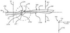
도 1a는 본 발명의 실시예에 따라 구성된 칫솔의 평면도.
도 1b는 도 1a의 칫솔의 베이스를 도시하는 평면도.
도 2a는 칫솔의 횡축을 도시하는, 도 1b의 베이스의 측면도.
도 2b는 도 2a의 베이스의 확대 측면도.
도 3a는 횡축에 평행하고 중간의 제1 경계 지점을 통해 연장되는 평면을 따른 도 2a의 베이스를 도시하는 단면도.
도 3b는 횡축에 평행하고 하부의 제1 경계 지점을 통해 연장되는 평면을 따른 도 2a의 베이스를 도시하는 단면도.
도 3c는 횡축에 평행하고 상부의 제1 경계 지점을 통해 연장되는 평면을 따른 도 2a의 베이스를 도시하는 단면도.
도 4a는 횡축에 평행하고 1차 중간 지점을 통해 연장되는 평면을 따른 도 2a의 베이스를 도시하는 단면도.
도 4b는 횡축에 평행하고 하부의 중간 지점을 통해 연장되는 평면을 따른 도 2a의 베이스를 도시하는 단면도.
도 4c는 횡축에 평행하고 상부의 중간 지점을 통해 연장되는 평면을 따른 도 2a의 베이스를 도시하는 단면도.
도 5a는 횡축에 평행하고 중간의 제2 경계 지점을 통해 연장되는 평면을 따른 도 2a의 베이스를 도시하는 단면도.
도 5b는 횡축에 평행하고 하부의 제2 경계 지점을 통해 연장되는 평면을 따른 도 2a의 베이스를 도시하는 단면도.
도 6은 도 2a의 베이스의 확대 측면도.
도 7a는 도 2a의 베이스의 확대 측면도.
도 7b, 도 7c, 및 도 7d는 도 1의 칫솔의 중간 영역의 제3 섹션을 도시하는 부분 사시도이며, 명료함을 위해 칫솔의 다른 특징부들 모두가 제거되어 있음.
도 8a, 도 8b, 및 도 8c는 도 1의 칫솔의 중간 영역의 제1 섹션 및 제2 섹션을 도시하는 부분 사시도이며, 명료함을 위해 칫솔의 다른 특징부들 모두가 제거되어 있음.
도 9a는 도 2a의 베이스의 확대 측면도.
<도 9b>
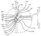
도 9b는 도 1의 칫솔의 중간 영역의 제4 섹션, 제5 섹션, 및 제6 섹션을 도시하는 부분 사시도.
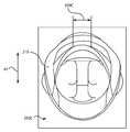
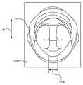
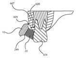
도 10은 부분 구강 내의 도 1의 칫솔을 도시하는 도면.BRIEF DESCRIPTION OF THE DRAWINGS Figure 1 a is a top view of a toothbrush constructed in accordance with an embodiment of the present invention.
Figure 1B is a plan view of the base of the toothbrush of Figure 1A;
Figure 2a is a side view of the base of Figure 1b, showing the abscissa axis of the toothbrush.
Figure 2b is an enlarged side view of the base of Figure 2a;
Figure 3a is a cross-sectional view of the base of Figure 2a along a plane parallel to the transverse axis and extending through a first boundary point in the middle;
Figure 3b is a cross-sectional view of the base of Figure 2a along a plane parallel to the transverse axis and extending through the first boundary point below;
Figure 3c is a cross-sectional view of the base of Figure 2a along a plane parallel to the transverse axis and extending through the first boundary point at the top;
Figure 4a is a cross-sectional view of the base of Figure 2a along a plane parallel to the transverse axis and extending through the primary midpoint;
Figure 4b is a cross-sectional view of the base of Figure 2a along a plane parallel to the transverse axis and extending through the midpoint of the bottom;
Figure 4c is a cross-sectional view of the base of Figure 2a along a plane parallel to the transverse axis and extending through an intermediate point at the top;
Figure 5a is a cross-sectional view of the base of Figure 2a along a plane parallel to the abscissa and extending through the middle second boundary point.
Figure 5b is a cross-sectional view of the base of Figure 2a along a plane parallel to the abscissa and extending through the second border point at the bottom;
Figure 6 is an enlarged side view of the base of Figure 2a.
Figure 7a is an enlarged side view of the base of Figure 2a.
Figures 7b, 7c, and 7d are partial perspective views illustrating a third section of the middle region of the toothbrush of Figure 1, with all other features of the toothbrush removed for clarity.
Figures 8A, 8B and 8C are partial perspective views showing first and second sections of the middle region of the toothbrush of Figure 1, with all other features of the toothbrush removed for clarity.
Figure 9a is an enlarged side view of the base of Figure 2a.
9B,
Figure 9b is a partial perspective view showing fourth, fifth, and sixth sections of the middle region of the toothbrush of Figure 1;
Figure 10 shows the toothbrush of Figure 1 in a partial cavity;
본 발명에 따라 구성된 구강 케어 기구는 복잡한 주형 부품을 피할 수 있는 사출 성형 공정을 이용하면서 복잡한 특징부 및/또는 형상을 포함할 수 있다. 구체적으로, 본 발명에 따라 설계된 구강 케어 기구는 수직 방향 주형 제거를 이용하면서 복잡한 형상을 포함할 수 있다. 하기에 기술된 실시예는 구강 케어 기구에 관한 것이지만, 하기의 교시는 다른 개인 케어 기구, 예를 들어 그루밍(grooming)(면도날, 면도기, 면도 도구) 등에 적용가능하다.The oral care implement constructed in accordance with the present invention may include complex features and / or features while utilizing an injection molding process that avoids complicated mold parts. Specifically, the oral care implement designed in accordance with the present invention may include complex shapes using vertical desoldering. While the embodiments described below relate to oral care devices, the following teachings are applicable to other personal care devices, such as grooming (razor blades, razors, shaving tools, etc.).
도 1a 및 도 1b에 도시된 바와 같이, 본 발명에 따라 구성된 구강 케어 기구, 예를 들어 칫솔은 베이스(210)(도 1b 및 도 2a 내지 도 2b에 도시됨)를 포함할 수 있다. 베이스(210)는 파지 영역(60) 및 구강 결합 영역(70)을 포함할 수 있다. 파지 영역(60)은 손잡이(12)의 일부분, 제1 파지 부재(20) 및 안내 요소(30)를 포함할 수 있다. 도시된 바와 같이, 제1 파지 부재(20)는 안내 요소(30)가 전방측 표면(260)의 일부를 형성하게 하는 개방부를 포함할 수 있다. 제1 파지 부재(20)는 파지 영역(60)을 적어도 부분적으로 덮는다.As shown in FIGS. 1A and 1B, a oral care instrument constructed in accordance with the present invention, for example, a toothbrush, may include a base 210 (shown in FIGS. IB and 2A-B). The
종축(40)은 구강 케어 기구(10)의 원위 단부(distal end)(80)로부터 구강 케어 기구(10)의 근위 단부(proximal end)(90)까지 연장된다. 측방향 축(42)은 종축(40)에 수직이고, 헤드(16)의 평면에 대체로 평행이다.The
구강 케어 기구(10)는 칼라(290)를 추가로 포함할 수 있다. 칼라(290)는 제1 파지 부재(20)와 단일형으로 형성될 수 있다. 베이스(210)는 칼라(290)를 위한 재료가 내부에 존재하는 리세스(277)를 포함할 수 있다. 리세스, 예를 들어 277 및 1279(도 7a에 도시됨)는, 이하에 논의되는 바와 같이, 수직 주형 제거를 여전히 허용하면서 복잡한 경사진 특징부를 포함할 수 있다. 리세스, 예를 들어 277 및 1279는 임의의 적합한 위치에 위치될 수 있다. 예를 들어, 리세스는 손잡이(12)와 목부(14) 사이에 위치될 수 있다. 그러한 실시예에서, 리세스는 목부(14)를 둘러쌀 수 있다. 그러나, 본 명세서에 제공된 원리는 구강 케어 기구 상의 임의의 위치에 경사진 요소를 생성하는 데 이용될 수 있다. 예를 들어, 손잡이(12), 목부(14), 헤드(16), 또는 이들의 조합은 본 명세서에 기술된 바와 같은 칼라를 포함할 수 있다.The
구강 케어 기구(10)는 헤드(16) 및 복수의 접촉 요소(200)를 포함하는 구강 결합 영역(70)을 추가로 포함할 수 있다. 목부(14)는 헤드(16)와 손잡이(12) 사이에서 연장되어서 구강 결합 영역(70)과 파지 영역(60)을 연결한다. 헤드(16) 및/또는 목부(14)는 손잡이(12)에 대해 경사질 수 있다. 부가적으로, 헤드(16)는 접촉 요소(200)가 그로부터 연장되는 상승된 표면(299)(도 2a에 도시됨)을 포함할 수 있다.The
상승된 표면(299)은 치아 표면에의 접촉 요소(200)의 보다 나은 도달을 제공할 수 있다. 도 10에 도시된 바와 같이, 일반적으로, 사용자의 잇몸(607)은 두께(608)가 변화할 수 있다. 이러한 변화하는 두께(608)는 칫솔과 치아(604) 사이의 거리를 한정할 수 있다. 상승된 표면(299) 때문에, 접촉 요소(200)는 치아(604)에 대한 보다 나은 접근을 갖는 것으로 여겨진다. 도시된 바와 같이, 칫솔과 잇몸(607) 사이의 간극(609)이 존재할 수 있지만, 칫솔이 상승된 표면(299)을 포함하기 때문에, 간극(609)에 가장 가까운 모서리가 부존재한다. 이러한 모서리의 부존재는 치아(604)에 대한 접촉 요소(200)의 더 가까운 위치설정을 허용한다. 대조적으로, 종래의 칫솔은 칫솔과 잇몸 사이의 간극의 거리에 영향을 미칠 수 있는, 간극 부근의 둥근 모서리를 포함할 수 있다.The raised
도 1a 및 도 1b를 다시 참조하면, 칫솔은 식별 기호부(50)를 포함할 수 있다. 식별 기호부(50)는 구강 케어 기구의 유형, 구강 케어 기구의 제조 회사, 및/또는 구강 케어 기구의 브랜드 명의 어떤 시각적 표시를 제공할 수 있다. 일부 실시예에서, 식별 기호부(50)는 복수의 재료를 포함할 수 있다. 예를 들어, 경질 재료가 특정의 문자 숫자식 부호 또는 다른 기호를 형성하는 데 이용될 수 있는 반면, 연질 재료가 이 문자 숫자식 부호 또는 다른 기호를 둘러싸거나 적어도 부분적으로 둘러쌀 수 있다. 다른 예로서, 연질 재료가 특정의 문자 숫자식 부호 또는 다른 기호를 형성하는 데 이용될 수 있는 반면, 더 경질의 재료가 이 문자 숫자식 부호 또는 다른 기호를 둘러싸거나 적어도 부분적으로 둘러쌀 수 있다.Referring again to FIGS. 1A and 1B, the toothbrush may include an
전술된 바와 같이, 제1 파지 부재(20)는 안내 요소(30)를 노출시키는 개방부를 포함할 수 있다. 안내 요소(30)는 베이스(210)와 단일형으로 형성될 수 있다. 부가적으로, 안내 요소(30)는 사용자에게 촉각적 단서를 제공하기 위해 제1 파지 부재(20)의 재료보다 더 경질인 재료를 포함할 수 있다.As described above, the first gripping
여전히 도 1a 및 도 1b를 참조하면, 베이스(210)는 손잡이 영역(120)에 제1 개구(220) 및 제2 개구(240)를 포함할 수 있다. 베이스(210)를 통해 연장되는 추가의 개구가 이용될 수 있다. 개구, 예를 들어 220 및 240은 제1 파지 부재(20)가 베이스(210)의 배면 상에 배치된 제2 파지 부재와 단일형으로 형성되게 할 수 있다. 제2 파지 부재 및 제1 파지 부재(20)는 제1 개구(220)를 통해 서로에 부착될 수 있다. 유사하게, 식별 기호부(50)는 제2 파지 부재와 단일형으로 형성되고 제2 개구(240)를 통해 그에 부착될 수 있다.Still referring to FIGS. 1A and 1B, the
베이스(210)는 칼라(290)를 위한 재료가 내부에 존재하는 리세스(277)를 포함할 수 있다. 칼라(290)는 제1 파지 부재(20)와 단일형으로 형성될 수 있다. 베이스(210)의 목부(14)는 재료의 스트립이 내부에 배치될 수 있는 채널을 포함할 수 있다. 재료의 스트립은 칼라(290)를 헤드(16) 내의 혀 세정기와 연결할 수 있다. 재료의 스트립, 혀 세정기 및 칼라(290)는 단일형으로 형성될 수 있다.The base 210 may include a
부가적으로, 구강 결합 영역(70) 내의 베이스(210)는 헤드(16)의 측에 복수의 만입부(indentation)를 포함할 수 있다. 만입부는 혀 세정기의 재료가 유동하여, 구강 케어 기구(10)의 헤드(16)의 상승된 표면(299)으로부터 연장되는 복수의 탄성중합체 요소를 형성하게 할 수 있다. 일부 실시예에서, 복수의 탄성중합체 요소는 혀 세정기와 단일형으로 형성될 수 있다.Additionally, the base 210 in the
가공 동안에, 제2 파지 부재에 이용되는 재료는 베이스(210)에 사출 성형될 수 있다. 사출 성형 작업은 제2 파지 부재를 형성하도록 베이스(210)의 후방 표면(270A)(도 2a에 도시됨) 상에 재료를 제공할 수 있다. 재료는 제1 개구(220) 및 제2 개구(240)를 통해 유동하여서 제1 파지 부재(20) 및 식별 요소(50)를 형성할 수 있다. 재료는 리세스(277)를 통해 유동하여서 칼라(290)를 형성할 수 있다. 재료는 채널을 통해 유동하여서 재료의 스트립을 형성하고 헤드(16)로 유동하여서 혀 세정기를 형성할 수 있다. 재료는 만입부를 통해 유동하여 복수의 탄성중합체 요소를 형성할 수 있다.During processing, the material used for the second gripping member may be injection molded into the
헤드(16)의 주변부 내측에 배치된 탄성중합체 요소를 포함하는 실시예의 경우, 개구가 헤드(16) 내에 제공되어서 혀 세정기(미도시)에 이용되는 재료가 헤드(16)를 통해 유동하여서 복수의 탄성중합체 요소(미도시)를 형성하게 할 수 있다. 부가적으로, 주변부 둘레에 배치된 탄성중합체 요소와 주변부 내측에 배치된 탄성중합체 요소 둘 모두를 포함하는 실시예의 경우, 만입부와 개구 둘 모두가 탄성중합체 요소를 형성하는 데 이용될 수 있다. 복수의 탄성중합체 요소 각각이 서로 일체형이고/일체형이거나 혀 세정기와 일체형인 실시예가 고려된다. 복수의 탄성중합체 요소가 헤드(16)의 주변부 내측에 배치되는 실시예의 경우, 복수의 탄성중합체 요소는 서로 일체형일 수 있다. 부가적으로, 그러한 실시예의 경우, 복수의 탄성중합체 요소는 혀 세정기와 일체형일 수 있다. 예를 들어, 복수의 탄성중합체 요소는 헤드(16) 내의 개구를 통해 연장되고 혀 세정기로부터 일체적으로 연장될 수 있다.For an embodiment that includes an elastomeric element disposed within the perimeter of the
독특하게, 베이스(210)를 가로지른 재료의 유동은 후방 표면(270A)으로부터 전방측 표면(260)으로 그리고 이어서 다시 후방 표면(270A)으로일 수 있다. 이러한 구성은 손잡이(12), 목부(14), 및/또는 헤드(16)를 위한 제3 재료의 사용 없이도 칫솔에 정교한 외관을 제공할 수 있다. 예를 들어, 이러한 구성은 제2 파지 부재와 칼라(290) 사이의 후방 표면(270A) 상에 분리부가 존재하는 것을 허용한다. 이러한 분리부는 심미적으로 매력적일 수 있다. 더욱이, 제2 파지 부재와 칼라(290) 사이의 분리부는 사용자에게 어떤 촉감을 제공할 수 있다. 칼라(290)와 제2 파지 부재가 분리되기 때문에, 더 경질의 재료가 칼라(290)와 제2 파지 부재 사이의 분리부에 제공될 수 있다. 더 경질의 재료는 분리부로부터 멀리 배치된 영역과는 대조적으로 분리부의 영역에서 제2 파지 부재에 추가의 저항력을 제공할 수 있다.Uniquely, the flow of material across the base 210 can be from the
전술된 바와 같이, 제2 파지 부재, 제1 파지 부재(20), 식별 요소(50), 칼라(290), 재료의 스트립, 혀 세정기, 및/또는 복수의 탄성중합체 요소는 단일형으로 형성될 수 있다. 그러나, 일부 실시예에서, 이들 중 적어도 하나, 예를 들어 제2 파지 부재, 제1 파지 부재(20), 식별 요소(50), 칼라(290), 재료의 스트립, 혀 세정기, 및/또는 복수의 탄성중합체 요소는 개별적으로 형성되고 베이스(210)에 부착될 수 있다. 제조 동안에 어쩌면 더 복잡하지만, 그러한 실시예는 이들 특징부를 위한 재료 선택에 있어서 상당한 유연성을 허용한다.As described above, the second gripping member, the first gripping
도 2a 및 도 2b에 도시된 바와 같이, 칼라(290)를 위한 리세스(277)는 목부(14)를 둘러쌀 수 있다. 리세스(277)는 제1 경계(277A) 및 제2 경계(277B)를 포함할 수 있다. 제1 경계(277A)는 목부(14)에 인접할 수 있는 반면, 제2 경계(277B)는 제1 파지 부재(20)에 인접할 수 있다. 리세스(277)는 제1 경계(277A)와 제2 경계(277B) 사이에 배치된 중간 영역(279)을 포함할 수 있다.2A and 2B, the
주형 분리선(280)은, 각각 교차점(319, 321)에서 제1 경계(277A) 및 제2 경계(277B)와 교차할 수 있다. 제1 경계(277A) 및/또는 제2 경계(277B)의 각도/곡률에 의해서도, 베이스(210)를 제조하는 데 이용되는 주형들이 수직 방향으로 제거될 수 있다. 예를 들어, 제1 주형 반부가 제1 방향(851)으로 제거될 수 있는 반면, 제2 주형 반부가 제1 방향(851)과는 반대인 제2 방향(852)으로 제거될 수 있다.The
도 1b 및 도 2a에 도시된 바와 같이, 제1 방향(851) 및 제2 방향(852)은 좌표계(700)의 Y 축(712)에 대체로 평행하다. 유사하게, 횡축(41)이 Y 축(712)에 대체로 평행하다. 종축(40)은 X 축(710)에 대체로 평행한 반면, 측방향 축(42)은 Z 축(714)과 대체로 평행하다.The
도 2a 및 도 2b를 다시 참조하면, 제1 경계(277A) 및/또는 제2 경계(277B)는 종축(40)에 수직인, 횡축(41) 또는 이에 평행한 선에 대해 경사질 수 있다. 제1 경계(277A)의 각도(450)는 약 5도 초과, 약 10도 초과, 약 15도 초과, 약 20도 초과, 약 30도 초과, 그리고/또는 약 30도 미만, 약 20도 미만, 약 15도 미만, 약 10도 미만, 또는 전술된 각도들 내의 임의의 범위 또는 임의의 수치일 수 있다.2A and 2B, the
일부 실시예에서, 각도(450)는 도 2b에 도시된 것과 반대로 배향될 수 있다. 예를 들어, 도 2b에 도시된 바와 같이, 각도(450)는 칫솔의 원위 단부(80)(도 1a에 도시됨)를 향해 경사진다. 그러나, 각도(450)가 칫솔의 근위 단부(90)(도 1a에 도시됨)를 향해 경사지는 실시예가 고려된다. 각도(450)는 경사에 무관하게 임의의 적합한 각도 크기일 수 있다. 적합한 각도 크기의 일부 예가 상기에 제공된다. 칫솔의 근위 단부를 향하는 각도(450)의 배향은 약 5도 초과, 약 10도 초과, 약 20도 초과, 약 30도 초과, 약 40도 초과, 약 50도 초과, 약 60도 초과, 그리고/또는 약 70도 미만, 약 60도 미만, 약 50도 미만, 약 40도 미만, 약 30도 미만, 약 20도 미만, 약 10도 미만, 또는 전술된 값들 내의 임의의 수치 또는 임의의 범위일 수 있다.In some embodiments,
제2 경계(277B)는 동일한 각도로 경사질 수 있다. 그러나, 일부 실시예에서, 제2 경계(277B)는 횡축(41)에 대해 약 10도 초과, 약 20도 초과, 약 30도 초과, 약 40도 초과, 약 50도 초과, 약 60도 초과, 약 70도 초과, 그리고/또는 약 70도 미만, 약 60도 미만, 약 50도 미만, 약 40도 미만, 약 30도 미만, 약 20도 미만, 약 10도 미만, 또는 전술된 각도들 내의 임의의 범위 또는 임의의 수치만큼 경사질 수 있다.The
수직 주형 제거를 수용하기 위해, 다양한 지점에서의 베이스(210)의 폭이 중요할 수 있다. 도 2a, 도 2b, 및 도 3a 내지 도 3c를 참조하면, 제1 경계(277A)를 따라, 베이스(210)는 주형 분리선(280)과 제1 경계(277A)의 교차점에 있는 중간의 제1 경계 지점(319A)을 통해 연장되는 중간의 제1 경계 폭(350A)을 포함할 수 있다. 여전히 제1 경계(277A)를 따라, 베이스(210)는 주형 분리선(280) 및 제1 경계(277A)를 따르고 중간의 제1 경계 지점(319A)에 대해 아래에 있는 하부의 제1 경계 지점(319B)을 통해 연장되는 하부의 제1 경계 폭(350B)을 포함할 수 있다. 제1 경계(277A)를 따라, 베이스(210)는 제1 경계(277A)의 최상부 부분에 있는 상부의 제1 경계 지점(319C)을 통해 연장되는 상부의 제1 경계 폭(350C)을 포함할 수 있다. 도 3a 내지 도 3c에 도시된 단면들 각각은 평면, 예를 들어 각각 355A, 355B, 및 355C - 이들 각각은 횡축(41)에 평행함 - 에서 취해진다. 부가적으로, 폭(350A, 350B, 350C) 각각은 측방향 축(42)(도 1b에 도시됨)에 대체로 평행하다.In order to accommodate vertical mold removal, the width of the base 210 at various points can be important. Referring to Figures 2A, 2B and 3A-C, along the
도 2a, 도 2b 및 도 4a 내지 도 4c를 참조하면, 중간 영역(279)에서, 베이스(210)는 1차 중간 영역 지점(323A) - 이곳에서 주형 분리선(280)이 중간 영역(279)의 (폭에 관하여) 가장 얇은 부분과 교차함 - 을 통해 연장되는 1차 중간 폭(370A)을 포함할 수 있다. 여전히 중간 영역(279)에서, 베이스(210)는 하부의 중간 영역 지점(323B)을 통해 연장되는 하부의 중간 영역 폭(370B)을 포함할 수 있다. 하부의 중간 영역 지점(323B)은 중간 영역(279) 내의 후방 표면(270A)의 일부를 형성하고, 중간 영역(279)의 (폭에 관하여) 가장 얇은 부분에 있다. 베이스(210)는 상부의 중간 영역 지점(323C)을 통해 연장되는 상부의 중간 영역 폭(370C)을 추가로 포함할 수 있다. 상부의 중간 영역 지점(323C)은 전방 표면(260) 상에 있고, 중간 영역(279)의 (폭에 관하여) 가장 얇은 부분에 있다. 도 4a 내지 도 4c에 도시된 단면들 각각은 평면, 예를 들어 각각 375A, 375B, 및 375C - 이들 각각은 횡축(41)에 평행함 - 에서 취해진다. 부가적으로, 폭(370A, 370B, 370C) 각각은 측방향 축(42)(도 1b에 도시됨)에 대체로 평행하다.Referring to FIGS. 2A, 2B and 4A-4C, in the
도 2a, 도 2b, 및 도 5a 내지 도 5b를 참조하면, 제2 경계(277B)를 따라, 베이스(210)는 주형 분리선(280)과 제2 경계(277B)의 교차점에 있는 중간의 제2 경계 지점(321A)을 통해 연장되는 중간의 제2 경계 폭(360A)을 포함할 수 있다. 여전히 제2 경계(277B)를 따라, 베이스(210)는 중간의 제2 경계 지점(321A)에 대해 아래에 배치되고 제2 경계(277B)를 따르는 하부의 제2 경계 지점(321B)을 통해 연장되는 하부의 제2 경계 폭(360B)을 포함할 수 있다. 하부의 제2 경계 지점(321B)은 후방 표면(270A) 상에 있다.Referring to Figures 2A, 2B and 5A-5B, along the
도 3a 내지 도 3c, 도 4a 내지 도 4c, 및 도 5a 내지 도 5b를 참조하면, 중간의 제1 경계 폭(350A)은 임의의 적합한 거리일 수 있다. 적합한 거리의 결정은 베이스(210)에 이용되는 재료의 유형에 좌우될 수 있다. 예를 들어, 중간의 제1 경계 폭(350A)은 중간의 제1 경계 폭(350A), 중간의 제2 경계 폭(360A), 및 1차 중간 폭(370A)의 영역에서의 파단 및/또는 피로 파괴를 방지하도록 크기설정되어야 한다. 중간의 제2 경계 폭(360A)은 약 5 ㎜ 초과, 약 6 ㎜ 초과, 약 7 ㎜ 초과, 약 8 ㎜ 초과, 약 9 ㎜ 초과, 약 10 ㎜ 초과, 약 11 ㎜ 초과, 약 12 ㎜ 초과, 약 13 ㎜ 초과, 약 15 ㎜ 초과, 약 16 ㎜ 초과, 그리고/또는 약 16 ㎜ 미만, 약 15 ㎜ 미만, 약 14 ㎜ 미만, 약 13 ㎜ 미만, 약 12 ㎜ 미만, 약 11 ㎜ 미만, 약 10 ㎜ 미만, 약 9 ㎜ 미만, 약 8 ㎜ 미만, 약 7 ㎜ 미만, 약 6 ㎜ 미만, 또는 제공된 거리들을 갖는 임의의 개별 수치 또는 범위일 수 있다. 일부 실시예에서, 중간의 제2 경계 폭(360A)은 약 10.7 ㎜일 수 있다.Referring to Figures 3A-3C, 4A-4C, and 5A-5B, the intermediate
중간의 제1 경계 폭(350A)은 임의의 적합한 거리일 수 있으며, 일부 실시예에서, 전술된 중간의 제2 경계 폭(360A)의 거리와 동일한 거리를 가질 수 있다. 일부 실시예에서, 중간의 제1 경계 폭(350A)은 약 10.6 ㎜일 수 있다. 유사하게, 1차 중간 폭(370A)은 임의의 적합한 거리일 수 있으며, 일부 실시예에서, 전술된 중간의 제2 경계 폭(360A)의 거리와 동일한 거리를 가질 수 있다. 일부 실시예에서, 1차 중간 폭(370A)은 약 10.1 ㎜일 수 있다.The intermediate
도 2a 및 도 2b, 도 3a 내지 도 3c, 도 4a 내지 도 4c, 및 도 5a 내지 도 5b를 다시 참조하면, 제1 방향(851) 및 제2 방향(852)에 있어서의 주형 분리선(280)을 따른 단순화된 주형 제거를 수용하기 위해, 본 명세서에 전술된 폭들은 주의 깊게 구성되어야 한다. 예를 들어, 중간의 제1 경계 폭(350A)의 경우, 주형 공동의 제거는 제1 기준선(390)을 따라 발생한다. 제1 방향(851)으로 제거되는 제1 주형 부분의 경우, 중간 영역(279)에서 중간의 제1 경계 지점(319A)과 상부의 제1 경계 지점(319C) 사이에 제1 언더컷이 발생할 수 있다. 언더컷의 가능성을 피하기 위해, 베이스(210)는 중간의 제1 경계 폭(350A)의 폭보다 더 큰, 제1 경계(277A)를 따른 폭을 갖지 않아야 한다. 또한, 베이스(210)는 1차 중간 폭(370A)의 폭보다 더 큰, 중간 영역(279)의 가장 얇은 부분을 따른 폭을 갖지 않아야 한다. 중간 영역(279)이 1차 중간 폭(370A)보다 더 큰 폭을 가질 수 있는 전이부(279A, 279B)를 포함할 수 있음에 유의해야 한다.Referring again to FIGS. 2A and 2B, 3A to 3C, 4A to 4C, and 5A to 5B, the
일부 실시예에서, 베이스(210)의 가장 넓은 부분(폭은 도 1b에 도시된 측방향 축(42)에 평행함)은 주형 제거선(280)을 따르거나 이에 인접해야 한다. 예를 들어, 전술된 바와 같이, 제1 방향(851)에 있어서의 주형 제거의 경우, 제1 기준선(390)은 중간의 제1 경계 폭(350A)을 형성하는 주형 부분에 대한 이동 경로를 나타낸다. (제1 방향(851)으로) 제1 기준선(390)을 따라, 베이스(210)의 가장 넓은 부분은 중간의 제1 경계 폭(350A)에 있을 수 있다.In some embodiments, the widest portion of the base 210 (the width parallel to the
제2 기준선(392)은 1차 중간 폭(370A)을 형성하는 주형 부분에 대한 이동 경로를 나타낸다. (제1 방향(851)으로) 제2 기준선(392)을 따라, 베이스(210)의 가장 넓은 부분은 1차 중간 폭(370A)에 있을 수 있다.The
제3 기준선(394)은 중간의 제2 경계 폭(360A)을 형성하는 주형 부분에 대한 이동 경로를 나타낸다. (제1 방향(851)으로) 제3 기준선(394)을 따라, 베이스(210)의 가장 넓은 부분은 중간의 제2 경계 폭(360A)에 있을 수 있다.And the
제2 방향(852)으로 제거되는 제2 주형 부분의 경우, 전이부(279B) 내의 중간 영역(279)에서 중간의 제2 경계 지점(321A)과 하부의 제2 경계 지점(321B) 사이에 제2 언더컷이 발생할 수 있다. 언더컷의 가능성을 피하기 위해, 기부(210)는 중간의 제2 경계 폭(360A)의 폭보다 더 큰, 제2 경계(277B)를 따른 폭을 갖지 않아야 한다. 또한, 베이스(210)는 1차 중간 폭(370A)의 폭보다 더 큰 폭을 갖는, 중간 영역(279)의 가장 얇은 부분을 따른 폭을 갖지 않아야 한다.In the case of the second mold part being removed in the
제2 방향(852)에 있어서의 주형 제거의 경우, 베이스(210)의 가장 넓은 부분은 주형 분리선(280)을 따르거나 이에 인접해야 한다. 제1 기준선(390)은 또한 2차 제1 경계 폭(351)(도 3a에 도시됨)을 형성하는 주형 부분에 대한 이동 경로를 나타낸다. 도 3a에 도시된 바와 같이, 2차 제1 경계 폭(351)은 중간의 제1 경계 폭(350A)의 것보다 약간 작다. 그러나, 2차 제1 경계 폭(351)이 하부 주형 부분에 의해 형성되기 때문에, 더 작은 2차 제1 경계 폭(351)은 상부 주형 부분에 관해서 언더컷을 생성하지 않는다. 도 2a 및 도 2b를 다시 참조하면, (제2 방향(852)으로) 제1 기준선(390)을 따라, 베이스(210)의 가장 넓은 부분은 2차 제1 경계 폭(351)(도 3a에 도시됨)에 있을 수 있다.In the case of mold removal in the
제2 기준선(392)은 1차 중간 폭(370A)을 형성하는 주형 부분에 대한 이동 경로를 나타낸다. (제2 방향(852)으로) 제2 기준선(392)을 따라, 베이스(210)의 가장 넓은 부분은 1차 중간 폭(370A)에 있을 수 있다.The
제3 기준선(394)은 2차 제2 경계 폭(361)(도 5a에 도시됨)을 형성하는 주형 부분에 대한 이동 경로를 나타낸다. 2차 제2 경계 폭(361)은 중간의 제2 경계 폭(360A)보다 약간 더 크지만, 중간의 제2 경계 폭(360A)이 주형의 상부 부분에 의해 형성되는 반면, 2차 제2 경계 폭(361)이 주형의 하부 부분에 의해 형성되기 때문에, 언더컷이 존재하지 않는다. 도 2a 및 도 2b를 다시 참조하면, (제2 방향(852)으로) 제3 기준선(394)을 따라, 베이스(210)의 가장 넓은 부분은 2차 제2 경계 폭(361)(도 5a에 도시됨)에 있을 수 있다.The
지금까지 기술된 폭들의 구성은 언더컷의 존재의 가능성을 크게 감소시킬 수 있다. 그렇기 때문에, 본 명세서에 기술된 바와 같은 베이스(210)의 구성은 제1 방향(851) 및 제2 방향(852)을 따른 수직 주형 제거를 이용하면서 심미적으로 만족스러운 칫솔을 제공할 수 있다.The configuration of the widths described so far can greatly reduce the possibility of the presence of undercuts. As such, the construction of the base 210 as described herein can provide an aesthetically pleasing toothbrush while utilizing vertical mold removal along the
도 6에 도시된 바와 같이, 주형 분리선(280)은 제1 방향(851) 및 제2 방향(852)으로의 주형 반부들의 제거를 수용하기 위해 중간 영역(279)에서 경사질 수 있다. 제2 경계(277B)와 전이부(279B)의 주형 분리선(280) 사이의 제1 각도(602)는 약 78.94도일 수 있다. 전이부(279A)의 주형 분리선(280)과 제1 경계(277A) 사이의 제2 각도(604)는 약 57.20도일 수 있다. 제1 경계(277A)를 따른 주형 분리선(280)과 종축(40) 사이의 제3 각도(606)는 약 107.20도일 수 있다. 임의의 적합한 각도가 이용될 수 있다.As shown in FIG. 6, the
도 2b를 다시 참조하면, 복잡한 기하학적 형상, 즉 경사진 특징부의 경우, 폭들의 조정은 매우 어려울 수 있다. 예를 들어, 제1 경계(277A)를 따른 단면이 1차 중간 폭(370A)보다 큰 일정한 폭을 포함한다면, 제2 기준선(392)은 제1 경계(277A)와 교차할 수 없고 복잡한 성형 구성요소의 사용 없이 제1 방향(851)으로의 수직 주형 제거를 여전히 유지할 수 있다. 그러나, 제1 경계(277A)를 따른 단면이 가변 폭을 포함하는 경우, 제2 기준선(392)은 기준선(392)과 제1 경계(277A) 사이의 교차점에서의 베이스(210)의 폭에 따라 제1 경계(277A)와 교차할 수 있다.Referring again to FIG. 2B, in the case of a complicated geometric shape, i.e., a sloped feature, adjustment of the widths can be very difficult. For example, if the cross-section along the
위에서 논의된 바와 같이, 칫솔의 특정 위치에서의 베이스(210)의 폭은 언더컷의 가능성을 감소시킬 수 있다. 그러나, 폭의 선택은 칫솔의 편안함 및 촉감을 고려해야 한다. 그래서, 넓은 각도가 제1 경계(277A) 상에서 달성가능할 수 있지만, 제2 기준선(392)과 제1 경계(277A) 사이의 교차점에서 베이스(210)의 폭이 상대적으로 작아야 하는 타협이 있을 수 있다. 이러한 디자인은 사용자에게 불편을 야기할 수 있고/있거나 불편한 칫솔에 관해서 소비자의 마음에 인식을 조장할 수 있다. 부가적으로, 베이스(210)의 더 작은 폭은 재료 파괴, 예를 들어 피로 파괴의 가능성을 증가시킬 수 있다.As discussed above, the width of the base 210 at a particular location of the toothbrush may reduce the likelihood of undercuts. However, the choice of width should take into account the comfort and feel of the toothbrush. Thus, although a wide angle may be achievable on the
일부 실시예에서, 넓은 각도가 제2 경계(277B)에 대해 채용되지만, 제2 방향(852)으로의 수직 주형 제거를 용이하게 하는 폭들을 수용하기 위해, 1차 중간 폭(370A)은 제2 기준선(392)과 제2 경계(277B)가 교차한다고 가정하여 하부의 제2 경계 폭(360B)을 수용하도록 증가되어야 할 수 있다. 1차 중간 폭(370A)의 증가는 칼라(290)(도 1a에 도시됨)를 위한 재료가 내부에 침착되는 리세스(277)의 깊이를 감소시킬 수 있다. 부가적으로, 리세스(277)의 감소된 깊이는 칫솔의 매력에 악영향을 미칠 수 있다. 예를 들어, 리세스(277) 내에 배치된 제2 재료가 사용자에게 연질 파지부를 제공하는 탄성중합체 조성물인 경우, 감소된 깊이는 리세스(277) 내의 탄성중합체 조성물에게는 더 작은 두께와 동일할 수 있다. 감소된 두께는 탄성중합체 조성물이 사용자에게 제공하는 완충의 양을 감소시킬 수 있다. 부가적으로, 탄성중합체 조성물의 감소된 두께는 또한 탄성중합체 조성물에 있어서의 반투명성을 촉진할 수 있다. 이러한 반투명성은 의도하지 않은 불쾌한 시각적 효과를 사용자에게 제공할 수 있다.In some embodiments, although a wide angle is employed for the
일부 실시예에서, 제2 기준선(392)은 제2 경계(277B)와 교차한다. 일부 실시예에서, 제2 기준선(392)은 제2 경계(277B)와 교차하지 않는다. 일부 실시예에서, 제2 기준선(392)은 제1 경계(277A)와 교차한다. 일부 실시예에서, 제2 기준선은 제1 경계(277A)와 교차하지 않는다.In some embodiments, the
이하에 기술되는 실시예의 경우, 칼라, 혀 세정기, 재료의 스트립, 제1 파지 부재, 및 제2 파지 부재가 그와 함께 포함될 수 있다. 도 7a를 참조하면, 일부 실시예에서, 예를 들어 제1 방향(1851)으로 그리고 제2 방향(1852)으로의 단순화된 주형 제거가, 칫솔 상에 3차원 특징부를 적절하게 설계함으로써 달성될 수 있다. 예를 들어, 적절하게, 제1 섹션(2110), 제2 섹션(2112), 및 제3 섹션(2114)을 갖는 리세스(1279)를 적절하게 설계함으로써, 언더컷이 제2 주형 제거 방향(1852)에 대해 제거될 수 있다. 단순화된 주형 제거는 칫솔 및 주형이 언더컷을 피하도록 생성될 때 발생한다. 제1 섹션(2110), 제2 섹션(2112), 및 제3 섹션(2114)은 도 7b에 도시된 3차원 좌표계(700)에 관하여 설계될 수 있다.For the embodiments described below, a collar, a tongue cleaner, a strip of material, a first gripping member, and a second gripping member may be included therewith. 7A, in some embodiments, a simplified mold removal, e.g., in a
여전히 도 7a를 참조하면, 제1 섹션(2110)은 주형 분리선(2280), 제2 경계(2177B), 및 횡축(42)(도 2a에 도시됨)에 대체로 평행한 제2 기준선(890)에 의해 한정된다. 제2 섹션(2112)은 제2 기준선(890), 중간 표면(2144), 및 중간 측부 표면(2146)에 의해 한정된다. 중간 측부 표면(2146)은 리세스(1279)의 가장 얇은 부분을 나타낸다. 제3 섹션(2114)은, 부분적으로, 제2 경계(2177B), 외측 표면(2148), 외측 경계(2178), 및 주형 분리선(2280)에 의해 한정된다.7A,
언더컷을 피하기 위해, 제1 섹션(2110)은 주형 부분이 제2 방향(1852)으로 제거될 수 있도록 설계되어야 한다. 유사하게, 제2 섹션(2112) 및 제3 섹션(2114)은 제2 주형 제거 방향(1852)을 수용하도록 설계되어야 한다. 제1 섹션(2110), 제2 섹션(2112), 및 제3 섹션(2114) 각각은 지금까지 기술된 바와 같이, 예를 들어 칫솔의 상대적 폭들에 관해서 설계될 수 있다. 부가적으로, 다른 특징부가 주형 제거 방향(1851 및/또는 1852)을 수용하는 데 이용될 수 있다. 예를 들어, 제1 섹션(2110), 제2 섹션(2112), 및 제3 섹션(2114)은 이들이 Y 축(712)(도 7b에 도시됨)에 대해 경사지도록 설계될 수 있다. 명료함을 위해, Y 축(712)은 제1 방향(1851) 및 제2 방향(1852)에 대해 대체로 평행하다.To avoid undercutting, the
주형 제거를 용이하게 하는 제3 섹션(2114)의 설계가 하기에 논의된다. 도 7b 내지 도 7d에 도시된 바와 같이, 제3 섹션(2114)은, 부분적으로, 제2 경계(2177B) 및 외측 경계(2178)에 의해 둘러싸인다. 제3 섹션(2114)은 제1 시작점(854) 및 제1 종료점(855)을 갖는다. 제1 시작점(854)에서, 제3 섹션(2114)은 Y 축(712)에 대해 약 21도의 제1 각도(2114A)를 갖는다. 제1 종료점(855)에서, 제3 섹션(2114)은 Y 축(712)에 대해 약 21도의 제2 각도(2114B)를 갖는다. 외측 표면(2148)은 Y 축(712)에 대해 약 11.67도의 외측 표면 각도(2114C)를 갖는다. 일부 실시예에서, 제1 각도(2114A) 및 제2 각도(2114B)는 외측 표면 각도(2114C)보다 약 10도만큼 더 클 수 있다.The design of the
제1 각도(2114A) 및 제2 각도(2114B)에 관해서, 임의의 적합한 각도가 이용될 수 있다. 예를 들어, 제1 각도(2114A) 및/또는 제2 각도(2114B)는 약 0.5도 초과, 약 1도 초과, 약 5도 초과, 약 10도 초과, 약 15도 초과, 약 20도 초과, 약 25도 초과, 약 30도 초과, 약 35도 초과, 약 40도 초과, 약 45도 초과, 그리고/또는 약 45도 미만, 약 40도 미만, 약 30도 미만, 약 25도 미만, 약 20도 미만, 약 15도 미만, 약 10도 미만, 약 5도 미만, 약 1도 미만, 또는 상기에 제공된 값들 내에 있는 임의의 개별 수치 또는 임의의 범위일 수 있다.With respect to the
유사하게, 외측 표면 각도(2114C)에 관해서, 임의의 적합한 각도가 이용될 수 있다. 일 예로서, 중간 지점 각도(2114C)는 약 0.5도 초과, 약 1도 초과, 약 5도 초과, 약 10도 초과, 약 15도 초과, 약 20도 초과, 약 25도 초과, 약 30도 초과, 그리고/또는 약 30도 미만, 약 25도 미만, 약 20도 미만, 약 15도 미만, 약 10도 미만, 약 5도 미만, 약 1도 미만, 그리고/또는 상기에 제공된 값들 내에 있는 임의의 개별 수치 또는 임의의 범위일 수 있다.Similarly, with respect to the
도 7c 및 도 7d에 도시된 바와 같이, 제1 각도(2114A) 및 제2 각도(2114B)는 Y 축(712)으로부터 XZ 평면(715)을 향해 내측으로, 예를 들어 제1 시작점(854)으로부터 제2 시작점(858)으로, 그리고 제1 종료점(855)으로부터 제2 종료점(859)으로 각각 경사질 수 있다. 유사하게, 외측 표면 각도(2114C)에 관해서, 제3 섹션(2114)은 Y 축(712)으로부터 XZ 평면(715)을 향해 경사질 수 있다. 도시된 바와 같이, 제3 섹션(2114)의 폭은 제3 섹션(2114)이 Y 축(712)을 따라 진행함에 따라 대체로 감소한다.7C and 7D, the
외측 표면(2148)의 곡률 반경(2170)은 변수(Xd, Yd, Zd)에 따라 달라질 수 있다. 본 발명에서, 곡률 반경(2170)은 임의의 적합한 값일 수 있다. 일부 실시예에서, 곡률 반경(2170)은 시작점 및 종료점에서 소정 각도를 갖는 한정된 반경을 갖는 원호에 의해, 서로 접선방향으로 연결되는 다수의 원호 또는 반경에 의해, 함수 R(x)로서 대략 기술될 수 있다. 일부 실시예에서, 반경(2170)은 약 2 ㎜ 내지 약 15 ㎜일 수 있다. 일부 실시예에서, 반경(2170)은 약 6 ㎜ 내지 약 7 ㎜일 수 있다. 일부 실시예에서, 반경(2170)은 약 6.6 ㎜일 수 있다. 또한, 복수의 원호와 유사한 세그먼트(segment)가 접선방향으로 연결되는 실시예 - 여기서 복수의 원호 세그먼트는 복수의 반경을 포함함 - 가 고려된다.The radius of
도 8a 내지 도 8c를 참조하면, 주형 제거 방향(1852)을 달성하기 위한 제2 섹션(2112) 및 제1 섹션(2110)의 설계가 하기에 논의된다. 제1 섹션(2110)은 주형 분리선(2280)을 따라 제2 시작점(873)까지 연장되는 에지를 갖는 제1 섹션 시작점(871)을 갖는다. 제1 섹션(2110)과 제2 섹션(2112) 사이의 분리선은 기준선(890)이다. 제2 섹션(2112)은 중간 표면(2144)을 포함한다. 제2 섹션(2112) 및 제1 섹션(2110)은, 부분적으로, 제2 경계(2177B)에 의해 둘러싸인다. 도시된 바와 같이, 제1 섹션(2110) 및 제2 섹션(2112)의 폭들은 제1 섹션(2110) 및 제2 섹션(2112)이 Y 축(712)을 따라 진행함에 따라 대체로 감소한다.8A-8C, the design of
제1 시작점(871)에서, 제1 섹션(2110)은 Z 축(714)에 대해 약 1.5도의 제1 각도(2110A)를 갖는다. 제1 종료점(872)에서, 제1 섹션(2110)은 Z 축(714)에 대해 약 1.5도의 제2 각도(2110B)를 갖는다. 중간 표면(2144)은 Y 축(712)에 대해 약 60도의 중간 표면 각도(2110C)를 갖는다. 일부 실시예에서, 제1 각도(2110A) 및 제2 각도(2110B)는 중간 표면 각도(2110C)보다 약 55도 초과만큼 더 작을 수 있다.At the
제1 각도(2110A) 및 제2 각도(2110B)에 관해서, 임의의 적합한 각도가 이용될 수 있다. 예를 들어, 제1 각도(2110A) 및/또는 제2 각도(2110B)는 약 0.5도 초과, 약 1도 초과, 약 5도 초과, 약 10도 초과, 약 15도 초과, 약 20도 초과, 약 25도 초과, 약 30도 초과, 약 35도 초과, 약 40도 초과, 약 45도 초과, 그리고/또는 약 45도 미만, 약 40도 미만, 약 30도 미만, 약 25도 미만, 약 20도 미만, 약 15도 미만, 약 10도 미만, 약 5도 미만, 약 1도 미만, 또는 상기에 제공된 값들 내에 있는 임의의 수치 또는 임의의 범위일 수 있다.With respect to the
유사하게, 중간 표면 각도(2110C)에 관해서, 임의의 적합한 각도가 이용될 수 있다. 일 예로서, 중간 표면 각도(2110C)는 약 0.5도 초과, 약 1도 초과, 약 5도 초과, 약 10도 초과, 약 15도 초과, 약 20도 초과, 약 25도 초과, 약 30도 초과, 약 40도 초과, 약 50도 초과, 약 60도 초과, 약 70도 초과, 약 80도 초과, 약 89도 초과, 그리고/또는 약 90도 미만, 약 80도 미만, 약 70도 미만, 약 60도 미만, 약 50도 미만, 약 40도 미만, 약 30도 미만, 약 25도 미만, 약 20도 미만, 약 15도 미만, 약 10도 미만, 약 5도 미만, 약 1도 미만, 그리고/또는 상기에 제공된 값들 내에 있는 임의의 개별 수치 또는 임의의 범위일 수 있다. 최대 중간 표면 각도(2110C)는 일부 실시예에서 89.5도를 초과하지 않아야 한다.Similarly, with respect to the
도 8b 및 도 8c에 도시된 바와 같이, 제1 각도(2110A) 및 제2 각도(2110B)는 Y 축(712)으로부터 XZ 평면(715)을 향해 내측으로, 예를 들어 제1 시작점(871)으로부터 제2 시작점(873)으로, 그리고 제1 종료점(872)으로부터 제2 종료점(874)으로 각각 경사질 수 있다. 유사하게, 중간 표면 각도(2110C)에 관해서, 제2 섹션(2112)은 Y 축(712)으로부터 XZ 평면(715)을 향해 경사질 수 있다.8B and 8C, the
제3 섹션(2114)(도 7a 내지 도 7d에 도시됨)과 유사하게, 제1 섹션(2110) 및/또는 제2 섹션(2112)은 변수(Xd, Yd, Zd)에 따라 달라질 수 있는 중간 표면(2144) 곡률을 가질 수 있다. 본 발명에서, 제1 섹션(2110) 및/또는 제2 섹션(2112)에 대한 곡률은 지금까지 기술된 반경(2170)과 유사하게 구성될 수 있다.Similar to the third section 2114 (shown in FIGS. 7A-7D), the
제1 주형 제거 방향(1851)에 관해서, 전술된 것과 유사한 설계 전략이 실행될 수 있다. 예를 들어, 도 9a에 도시된 바와 같이, 제4 섹션(905), 제5 섹션(907), 및 제6 섹션(909)의 적절한 설계는 언더컷의 가능성을 감소시키는 것을 도울 수 있다. 제4 섹션(905)은 제1 경계(2177A) 및 횡축(42)(도 2a에 도시됨)에 평행한 중간 경계(921)에 의해 한정되며, 상부의 제1 경계 지점(1319C)으로부터 주형 분리선(2280)까지 연장된다. 제4 섹션(905)은 칫솔(1000)이 적절하게 구성되지 않은 경우 가능성이 있는 언더컷 후보이다.With respect to the first
제5 섹션(907)은 리세스(1279)(도 1a에 도시된 측방향 축(41)에 관해서 그의 가장 얇은 부분), 중간 경계(921), 및 주형 분리선(2280)에 의해 한정된다. 제6 섹션(909)은 본 발명의 칫솔(1000)의 목부(1400)의 일부분이다. 제6 섹션(909)은 제1 경계(2177A), 칫솔(1000)의 상부 표면(1260), 및 주형 분리선(2280)에 의해 한정된다.The
제1 기준선(990)은 중간의 제1 경계 지점(1319A)과 관련된 폭을 형성하는 주형 부분에 대한 이동 경로를 나타낸다. 제2 기준선(992)은 1차 중간 영역 지점(1323A)과 관련된 폭을 형성하는 주형 부분에 대한 이동 경로를 나타낸다. 제3 기준선(994)은 중간의 제2 경계(1321A)와 관련된 폭을 형성하는 주형 부분에 대한 이동 경로를 나타낸다.The
도 9b를 참조하면, 제4 섹션(905)은 Y 축(712)으로부터 X 축(710)까지의 약 45도의 1차 각도(905A)를 가질 수 있다. 1차 각도(905A)는 임의의 적합한 수치일 수 있다. 예를 들어, 일부 실시예에서, 1차 각도(905A)는 약 3도 초과, 약 10도 초과, 약 20도 초과, 약 30도 초과, 약 40도 초과, 약 50도 초과, 약 60도 초과, 약 70도 초과, 약 80도 초과, 그리고/또는 약 90도 미만, 약 80도 미만, 약 70도 미만, 약 60도 미만, 약 50도 미만, 약 40도 미만, 약 30도 미만, 약 20도 미만, 약 10도 미만, 약 5도 미만, 또는 상기에 제공된 값들 내의 임의의 수치 또는 임의의 범위일 수 있다.Referring to FIG. 9B, the
제5 섹션(907)은 1차 각도(907A), 2차 각도(907B), 및 3차 각도(907C)를 가질 수 있다. 유사하게, 제6 섹션(909)은 1차 각도(909A), 2차 각도(909B), 3차 각도(909C), 및 4차 각도(909D)를 가질 수 있다.The
1차 각도(907A) 및 3차 각도(907C)는, 일부 실시예에서, Y 축(712)으로부터 Z 축(714)까지의 동일한 크기, 예를 들어 약 11도를 포함할 수 있다. 그러나, 1차 각도(907A)와 3차 각도(907C) 둘 모두는 임의의 적합한 값을 포함할 수 있다. 예를 들어, 이들 각도는 약 0.5도 초과, 약 1.0도 초과, 약 1.5도 초과, 약 5도 초과, 약 10도 초과, 약 15도 초과, 약 20도 초과, 약 25도 초과, 약 30도 초과, 그리고/또는 약 35도 미만, 약 30도 미만, 약 25도 미만, 약 20도 미만, 약 15도 미만, 약 10도 미만, 약 5도 미만, 약 1.5도 미만, 약 1도 미만, 또는 상기에 제공된 값들 내의 임의의 수치 또는 임의의 범위인 크기를 가질 수 있다.The
2차 각도(907B)는 Y 축(712)으로부터 Z 축(714)까지 약 70도일 수 있지만, 임의의 적합한 값이 이용될 수 있다. 일부 실시예에서, 2차 각도(907B)는 약 45도 초과, 약 55도 초과, 약 65도 초과, 약 75도 초과, 약 85도 초과, 그리고/또는 약 90도 미만, 약 85도 미만, 약 75도 미만, 약 65도 미만, 약 55도 미만, 또는 상기에 제공된 값들 내의 임의의 수치 또는 임의의 범위의 크기를 가질 수 있다.The
1차 각도(909A)는 Y 축(712)으로부터 X 축(710)까지 약 80도일 수 있다. 일부 실시예에서, 1차 각도(909A)는 약 3도 초과, 약 10도 초과, 약 20도 초과, 약 30도 초과, 약 40도 초과, 약 50도 초과, 약 60도 초과, 약 70도 초과, 약 80도 초과, 그리고/또는 약 90도 미만, 약 80도 미만, 약 70도 미만, 약 60도 미만, 약 50도 미만, 약 40도 미만, 약 30도 미만, 약 20도 미만, 약 10도 미만, 약 5도 미만, 또는 상기에 제공된 값들 내의 임의의 수치 또는 임의의 범위일 수 있다.The
2차 각도(909B) 및 4차 각도(909D)는, 일부 실시예에서, Y 축(712)으로부터 Z-축(714)까지의 동일한 값, 예를 들어 약 16도를 가질 수 있다. 일부 실시예에서, 2차 각도(909B) 및 제4 각도(909D)는 약 0.5도 초과, 약 1.0도 초과, 약 1.5도 초과, 약 5도 초과, 약 10도 초과, 약 15도 초과, 약 20도 초과, 약 25도 초과, 약 30도 초과, 약 35도 초과, 약 40도 초과, 그리고/또는 약 45도 미만, 약 40도 미만, 약 35도 미만, 약 30도 미만, 약 25도 미만, 약 20도 미만, 약 15도 미만, 약 10도 미만, 약 5도 미만, 약 1.5도 미만, 약 1도 미만, 또는 상기에 제공된 값들 내의 임의의 수치 또는 임의의 범위일 수 있다.
3차 각도(909C)는, 일부 실시예에서, Y 축(712)으로부터 Z 축(714)까지 약 41도일 수 있다. 일부 실시예에서, 3차 각도(909C)는 약 3도 초과, 약 10도 초과, 약 20도 초과, 약 30도 초과, 약 40도 초과, 약 50도 초과, 약 60도 초과, 약 70도 초과, 약 80도 초과, 그리고/또는 약 90도 미만, 약 80도 미만, 약 70도 미만, 약 60도 미만, 약 50도 미만, 약 40도 미만, 약 30도 미만, 약 20도 미만, 약 10도 미만, 약 5도 미만, 또는 상기에 제공된 값들 내의 임의의 수치 또는 임의의 범위인 값을 가질 수 있다.The
언더컷 이외에, 발생할 수 있는 다른 문제는 버링(burring)이다. 버(bur)는 주형 부품 에지 부근에서 박막이 생성될 때 발생한다. 도 2b, 도 3a, 및 도 5b를 다시 참조하면, 중간 영역(279) 내의 주형 분리선(280) 부근에서, 주형 부품들은 하나의 주형 부분을 넘어 주형 부분들 사이의 영역 내로의 누출의 가능성을 감소시키기 위해 안착 부분을 필요로 할 수 있다. 그렇기 때문에, 도 3a에 도시된 바와 같이, 평평한 안착 부분(311A, 311B)이 하부 주형 공동에 대해 베이스(210)의 양쪽에 제공된다. 이들 평평한 안착 부분(311A, 311B)은 버링의 가능성을 감소시킬 수 있다. 유사하게, 도 5a에 도시된 바와 같이, 평평한 안착 부분(313A, 313B)이 상부 주형 공동에 대해 베이스(210)의 양쪽에 제공될 수 있다. 이들 평평한 안착 부분(313A, 313B)은 버링의 가능성을 감소시킬 수 있다.In addition to the undercut, another problem that can occur is burring. The bur occurs when a thin film is produced near the edge of the mold part. Referring again to Figures 2b, 3a, and 5b, in the vicinity of the
임의의 적합한 재료가 본 명세서에 기술된 구강 케어 기구에 대해 이용될 수 있다. 예를 들어, 베이스(210)(도 1b, 도 2a 내지 도 2b, 도 3a 내지 도 3c, 도 4a 내지 도 4c, 및 도 5a 내지 도 5b에 도시됨)는 폴리에틸렌 (PE), 폴리프로필렌 (PP), 폴리에틸렌테레프탈레이트 (PET), 아크릴로니트릴-부타디엔-스티렌 (ABS), 스티렌-아크릴로니트릴 (SAN), PP 및 열가소성 탄성중합체 (TPE) 블렌드, 아세탈 (POM), 나일론 (PA), 개질된 폴리페닐렌 옥사이드 (PPO), 폴리에스테르 (PBT), 폴리카르보네이트 (PC), 고충격 폴리스티렌 (HIPS), 아이소플라스트 및 다른 열가소성 우레탄 (TPU) 재료 등, 및 이들의 적합한 조합을 포함할 수 있다.Any suitable material may be used for the oral care implement described herein. For example, the base 210 (shown in Figures 1B, 2A-2B, 3A-3C, 4A-4C, and 5A-5B) is made of polyethylene (PE), polypropylene ), Polyethyleneterephthalate (PET), acrylonitrile-butadiene-styrene (ABS), styrene-acrylonitrile (SAN), PP and thermoplastic elastomer (TPE) blends, acetal (POM), nylon (PPO), polyester (PBT), polycarbonate (PC), high impact polystyrene (HIPS), isoplast and other thermoplastic urethane (TPU) materials, and the like, as well as suitable combinations thereof can do.
제1 파지 부재(20), 제2 파지 부재, 칼라(290), 재료의 스트립, 혀 세정기, 및/또는 탄성중합체 요소는 임의의 적합한 열가소성 탄성중합체를 포함할 수 있다. 일부 적합한 예는 SEBS (스티렌-에틸렌-부틸렌-스티렌 블록 공중합체) 또는 열가소성 폴리우레탄을 포함한다. 일부 실시예에서, 제1 파지 부재(20), 제2 파지 부재, 칼라(290), 재료의 스트립, 혀 세정기, 및/또는 탄성중합체 요소에 이용되는 재료는 사용자에게 특정 이익을 제공하도록 선택될 수 있다. 예를 들어, 제1 파지 부재(20)에서 선택되는 재료는 복수의 탄성중합체 요소에 이용되는 재료보다 더 연질일 수 있다. 다른 예에서, 제1 파지 부재(20), 제2 파지 부재, 칼라(290), 재료의 스트립, 혀 세정기, 및/또는 탄성중합체 요소에 이용되는 재료에 첨가제가 포함될 수 있다. 일부 실시예에서, 재료에 심미적 매력을 제공하기 위해 첨가제가 첨가될 수 있다. 일 예로서, 글리터(glitter)가 재료에 첨가될 수 있다. 일부 실시예에서, 제1 파지 부재(20)에 이용되는 재료는 탄성중합체 재료를 이용하는 칫솔의 모든 부분에 사용될 수 있다.The first gripping
부가적으로, 본 명세서에 사용된 바와 같이, 용어 "접촉 요소"는 구강 내로 삽입될 수 있는 임의의 적합한 요소를 말하는 데 사용된다. 일부 적합한 요소는 강모 터프트(bristle tuft), 탄성중합체 마사지 요소, 탄성중합체 접촉 요소, 마사지 요소, 혀 세정기, 연조직 세정기, 경질 표면 세정기, 이들의 조합 등을 포함한다. 헤드는 다양한 접촉 요소를 포함할 수 있다. 예를 들어, 헤드는 강모, 탄성중합체 연마 요소, 특정 배향 또는 배열의 탄성중합체 요소, 예를 들어 피벗팅 핀(pivoting fin), 프로피 컵(prophy cup) 등을 포함할 수 있다. 탄성중합체 접촉 요소 및/또는 마사지 요소의 일부 적합한 예가 미국 특허 출원 공개 제2007/0251040호, 제2004/0154112호, 제2006/0272112호, 및 미국 특허 제6,553,604호, 제6,151,745호에 기술되어 있다. 접촉 요소는 테이퍼 형성되거나, 노치 형성되거나, 크림핑되거나, 딤플 형성되거나 등등일 수 있다. 이들 접촉 요소 및/또는 마사지 요소의 일부 적합한 예가 미국 특허 제6,151,745호, 제6,058,541호, 제5,268,005호, 제5,313,909호, 제4,802,255호, 제6,018,840호, 제5,836,769호, 제5,722,106호, 제6,475,553호, 및 미국 특허 출원 공개 제2006/0080794호에 기술되어 있다.Additionally, as used herein, the term "contact element" is used to refer to any suitable element that can be inserted into the oral cavity. Some suitable elements include bristle tufts, elastomeric massaging elements, elastomeric contact elements, massage elements, tongue cleaners, soft tissue cleaners, hard surface cleaners, combinations thereof, and the like. The head may include various contact elements. For example, the head may include a bristle, an elastomeric polishing element, an elastomeric element of a particular orientation or arrangement, such as a pivoting fin, a prophy cup, and the like. Some suitable examples of elastomeric contact elements and / or massage elements are described in U.S. Patent Application Publication Nos. 2007/0251040, 2004/0154112, 2006/0272112, and U.S. Patent Nos. 6,553,604 and 6,151,745. The contact element may be tapered, notched, crimped, dimpled or the like. Some suitable examples of these contact elements and / or massage elements are disclosed in U.S. Patent Nos. 6,151,745, 6,058,541, 5,268,005, 5,313,909, 4,802,255, 6,018,840, 5,836,769, 5,722,106, 6,475,553, And U.S. Patent Application Publication No. 2006/0080794.
일부 실시예에서, 접촉 요소(200)는 터프트를 포함할 수 있다. 터프트는 접촉 요소 캐리어에 견고하게 부착된 복수의 개별 필라멘트를 포함할 수 있다. 그러한 필라멘트는 중합체일 수 있으며, 폴리아미드 또는 폴리에스테르를 포함할 수 있다. 본 발명의 필라멘트의 종단면 및 횡단면 치수들과 필라멘트 단부의 프로파일은 변동될 수 있다. 부가적으로, 필라멘트 단부의 강성도(stiffness), 탄성(resiliency) 및 형상은 변동될 수 있다. 적합한 치수의 일부 예는 약 3 ㎝ 내지 약 6 ㎝, 또는 이 범위 내의 임의의 개별 수치의 길이를 포함한다. 부가적으로, 필라멘트는 약 100 내지 약 350 마이크로미터, 또는 이 범위 내의 임의의 개별 수치의 실질적으로 균일한 단면 치수를 포함할 수 있다. 필라멘트의 팁은 임의의 적합한 형상일 수 있으며, 그 예는 매끄러운 팁, 둥근 팁, 뾰족한 팁(테이퍼 형성됨), 및/또는 플래그형(flagged) 팁을 포함한다. 부가적으로, 단일 터프트가 여러 터프트들의 조합, 예를 들어 테이퍼 형성되고 둥근 것, 테이퍼 형성되고 플래그형인 것 등을 포함하는 실시예가 고려된다. 일부 실시예에서, 필라멘트는 미국 특허 제4,802,255호에 기술된 바와 같이 필라멘트의 마모를 나타내는 염료를 포함할 수 있다. 본 발명의 칫솔과 함께 사용하기에 적합한 필라멘트의 일부 예가 미국 특허 제6,199,242호에 기술되어 있다. 일부 실시예에서, 접촉 요소는 지금까지 기술된 바와 같은 핀(fin)을 포함할 수 있다. 예를 들어, 일부 실시예에서, 접촉 요소 영역은 핀과 터프트의 조합을 포함할 수 있다.In some embodiments, the
접촉 요소는 임의의 적합한 방식으로 헤드에 부착될 수 있다. 종래의 방법은 스테이플링(stapling), 앵커 프리 터프팅(anchor free tufting), 및 사출 성형 터프팅(injection mold tufting)을 포함한다. 탄성중합체를 포함하는 접촉 요소의 경우, 이들 요소는 서로 일체형으로 형성될 수 있는데, 예를 들어 일체형 베이스 부분을 갖고 이로부터 외측으로 연장된다.The contact element can be attached to the head in any suitable manner. Conventional methods include stapling, anchor free tufting, and injection mold tufting. In the case of a contact element comprising an elastomer, these elements may be integrally formed with one another, for example having an integral base portion and extending outwardly therefrom.
일부 실시예에서, 구강 케어 기구(10)는 혀 세정기를 포함할 수 있다. 혀 세정기는 헤드(16)의 후방측의 리세스 내에 배치될 수 있다. 혀 세정기는 구강 내의 악취 유발 물질의 양을 감소키는 데 이용될 수 있는 복수의 혀 세정 구조물을 포함할 수 있다. 혀 세정기에 적합한 재료의 일부 예는 탄성중합체 재료; 폴리프로필렌, 폴리에틸렌 등; 및/또는 이들의 조합을 포함한다. 혀 세정기는 임의의 적합한 연조직 접촉 요소를 포함할 수 있다. 그러한 요소뿐만 아니라 칫솔 상의 연조직 클렌저의 구성의 일부 예가 미국 특허 출원 제2006/0010628호; 제2005/0166344호; 제2005/0210612호; 제2006/0195995호; 제2008/0189888호; 제2006/0052806호; 제2004/0255416호; 제2005/0000049호; 제2005/0038461호; 제2004/0134007호; 제2006/0026784호; 제20070049956호; 제2008/0244849호; 제2005/0000043호; 제2007/140959호; 및 미국 특허 제5,980,542호; 제6,402,768호; 및 제6,102,923호에 기술되어 있다.In some embodiments, the
본 발명은 세정 운동이 완전히 사용자에 의해 공급되는 수동식 칫솔에 이용될 수 있다. 그러나, 본 발명이 미국 특허 출원 공개 제2003/0162145호에 기술된 바와 같은 진동 장치로 사용자의 운동을 보충하는 수동식 칫솔을 포함하는 실시예가 고려된다. 더욱이, 본 발명이 전동식 칫솔을 포함하는 실시예가 고려된다. 전동식 칫솔은 세정 운동의 대부분을 칫솔이 제공하는 칫솔이다. 사용자는 전동식 칫솔이 원하는 구강 표면과 접촉하는 것을 보장하도록 전동식 칫솔을 조작할 수 있다. 그러한 실시예에서, 접촉 요소는 다양한 운동으로 구동될 수 있다. 그러한 적합한 운동의 일부 예가 미국 특허 출원 공개 제2003/0084527호에 기술되어 있다. 또한, 본 발명이 전동식 및/또는 수동식 칫솔을 위한 교체가능한 칫솔 헤드를 포함하는 실시예가 고려된다.The present invention can be used in a hand-held toothbrush in which the cleaning movement is fully user supplied. However, there are contemplated embodiments in which the present invention includes a hand-held toothbrush that replenishes the user's movement with a vibrating device as described in U. S. Patent Application Publication No. 2003/0162145. Moreover, embodiments in which the present invention includes an electric toothbrush are contemplated. An electric toothbrush is a toothbrush provided with a toothbrush for most of the cleaning movement. The user can manipulate the electric toothbrush to ensure that the powered toothbrush contacts the desired oral surface. In such an embodiment, the contact element can be driven in a variety of motions. Some examples of such suitable movements are described in U.S. Patent Application Publication 2003/0084527. It is also contemplated that the present invention includes an interchangeable toothbrush head for an electric and / or manual toothbrush.
본 명세서에 개시된 치수 및 값은 기재된 정확한 수치 값으로 엄격히 제한되는 것으로 이해되어서는 안 된다. 대신에, 달리 명시되어 있지 않는 한, 각각의 그러한 치수는 기재된 값과 그 값 주변의 기능적으로 동등한 범위 둘 모두를 의미하는 것으로 의도된다. 예를 들어, "40 ㎜"로 개시된 치수는 "약 40 ㎜"를 의미하는 것으로 의도된다.It is to be understood that the dimensions and values disclosed herein are not strictly limited to the exact numerical values set forth. Instead, each such dimension is intended to mean both the stated value and a functionally equivalent range around the value, unless otherwise specified. For example, a dimension disclosed as "40 mm" is intended to mean "about 40 mm ".
임의의 상호 참조 또는 관련 특허 또는 출원을 포함한 본 명세서에 인용된 모든 문헌은 이에 의해, 명시적으로 배제되거나 달리 제한되지 않는 한, 전체적으로 본 명세서에 참고로 포함된다. 임의의 문헌의 인용은 그것이 본 명세서에서 개시 또는 청구된 임의의 발명에 대한 종래 기술임을, 또는 그것이 단독으로 또는 임의의 다른 참고문헌 또는 참고문헌들과의 임의의 조합으로 임의의 그러한 발명을 교시, 암시 또는 개시함을 인정하는 것이 아니다. 또한, 본 명세서의 용어의 임의의 의미 또는 정의가 참고로 포함된 문헌의 동일한 용어의 임의의 의미 또는 정의와 충돌하는 경우, 본 명세서의 그 용어에 대해 부여된 의미 또는 정의에 따른다.All references cited herein, including any cross-references or related patents or applications, are hereby incorporated by reference in their entirety, unless expressly excluded or otherwise limited. The citation of any document indicates that it is prior art to any invention disclosed or claimed herein, or that any such invention, by itself, or in any combination with any other reference or reference, Nor does it acknowledge that it is implied or initiated. In addition, where any meaning or definition of a term conflicts with any meaning or definition of the same term in a document incorporated by reference, it shall be subject to the meanings or definitions given for that term in this specification.
본 발명의 특정 실시예가 도시되고 설명되었지만, 다양한 다른 변경 및 변형이 본 발명의 사상 및 범주로부터 벗어남이 없이 이루어질 수 있음이 당업자에게 명백할 것이다. 따라서 본 발명의 범주 내에 있는 모든 그러한 변경 및 변형을 첨부된 특허청구범위에 포함시키고자 한다.
While particular embodiments of the invention have been illustrated and described, it will be apparent to those skilled in the art that various other changes and modifications can be made without departing from the spirit and scope of the invention. It is therefore intended to cover in the appended claims all such changes and modifications that are within the scope of the invention.
Claims (15)
Translated fromKorean상기 리세스 내에 배치된 제2 재료를 포함하는 칼라(collar)(290)로서, 상기 제2 재료는 상기 제1 재료보다 더 연질인, 상기 칼라
를 포함하는 구강 케어 기구 (10).A base (210) having a handle region (120), a mouth engagement region (70), a neck (14,1400) between said handle region and said oral engagement region, said base comprising a handle And / or a recess (277, 1279) surrounding the neck and having a first boundary (277A, 2177A) and a second boundary (277B, 2177B) 2 boundary than the distal end 80 and the first boundary is disposed obliquely at an angle greater than 90 degrees with respect to the mold parting line 280, 2280 of the oral care instrument Wherein the recess further comprises an intermediate region disposed between the first boundary and the second boundary and wherein the intermediate region has a different width along the length of the intermediate region, A first portion extending through a point intersecting the thinnest portion of the width of the intermediate region Wherein the first boundary is disposed midway between the first boundary and the second boundary, wherein the first boundary is formed by the mold separation lines (280, 2280) of the oral care instrument Is disposed at an angle of more than 5 degrees with respect to the transverse axis (41), which is perpendicular to the longitudinal axis (40) in the extending direction, the base comprising a first material; And
A collar (290) comprising a second material disposed in the recess, the second material being softer than the first material, the collar
(10).
상기 제2 재료는 탄성중합체인 것을 특징으로 하는 구강 케어 기구.The method according to claim 1,
Wherein the second material is an elastomeric material.
상기 제2 경계는, 구강 케어 기구의 상기 주형 분리선(280, 2280)이 연장되는 방향인 상기 종축 (40) 과 수직인, 상기 횡축 (41) 에 대해 10도 초과의 각도로 있는 것을 특징으로 하는 구강 케어 기구.3. The method according to claim 1 or 2,
Characterized in that said second boundary is at an angle greater than 10 degrees with respect to said transverse axis (41), perpendicular to said longitudinal axis (40) in the direction in which said mold separation lines (280, 2280) Oral care equipment.
상기 리세스는 상기 목부를 둘러싸는 것을 특징으로 하는 구강 케어 기구.3. The method according to claim 1 or 2,
Wherein the recess surrounds the neck.
상기 구강 케어 기구는 전방 표면(260)의 적어도 일부분을 형성하는 제1 파지 부재(20)를 추가로 포함하는 것을 특징으로 하는 구강 케어 기구.The method according to claim 1,
Wherein the oral care instrument further comprises a first gripping member (20) forming at least a portion of a front surface (260).
상기 구강 케어 기구는 상기 제1 파지 부재 내의 개방부 내에 배치된 안내 요소(30)를 추가로 포함하는 것을 특징으로 하는 구강 케어 기구.6. The method of claim 5,
Wherein said oral care instrument further comprises a guiding element (30) disposed in an opening in said first gripping member.
상기 제1 파지 부재 및 상기 칼라는 단일형인 것을 특징으로 하는 구강 케어 기구.6. The method of claim 5,
Wherein the first gripping member and the collar are unitary.
상기 안내 요소는 상기 제1 재료를 포함하고 상기 제1 파지 부재는 상기 제2 재료를 포함하는 것을 특징으로 하는 구강 케어 기구.The method according to claim 6,
Wherein the guide element comprises the first material and the first gripping member comprises the second material.
상기 구강 케어 기구는 상기 베이스의 후방 표면(270A) 상에 위치된 제2 파지 부재를 추가로 포함하는 것을 특징으로 하는 구강 케어 기구.6. The method of claim 5,
Wherein the oral care instrument further comprises a second gripping member located on a rear surface (270A) of the base.
상기 베이스는 상기 제1 파지 부재와 상기 제2 파지 부재가 단일형이 되도록 복수의 개구(220, 240)를 추가로 포함하는 것을 특징으로 하는 구강 케어 기구.10. The method of claim 9,
Wherein the base further comprises a plurality of openings (220, 240) such that the first gripping member and the second gripping member are unitary.
상기 제1 파지 부재, 상기 제2 파지 부재, 및 상기 칼라는 단일형인 것을 특징으로 하는 구강 케어 기구.11. The method of claim 10,
Wherein the first gripping member, the second gripping member, and the collar are of a single shape.
상기 구강 케어 기구는 상기 구강 결합 영역의 배면 상에 배치된 혀 세정기를 추가로 포함하는 것을 특징으로 하는 구강 케어 기구.3. The method according to claim 1 or 2,
Wherein said oral care mechanism further comprises a tongue cleaner disposed on a back side of said oral cavity region.
상기 구강 케어 기구는 상기 혀 세정기와 상기 제2 파지 부재 사이에서 연장되고 상기 혀 세정기 및 상기 제2 파지 부재와 단일형으로 형성되는 재료의 스트립을 추가로 포함하는 것을 특징으로 하는 구강 케어 기구.13. The method of claim 12,
Wherein the oral care instrument further comprises a strip of material extending between the tongue cleaner and the second grip member and formed integrally with the tongue cleaner and the second grip member.
상기 베이스는 상기 제2 파지 부재와 상기 혀 세정기 사이에서 연장되는 채널을 추가로 포함하고, 상기 재료의 스트립은 상기 채널 내에 배치되는 것을 특징으로 하는 구강 케어 기구.14. The method of claim 13,
Wherein the base further comprises a channel extending between the second gripping member and the tongue cleaner, wherein a strip of the material is disposed within the channel.
상기 제1 파지 부재, 상기 제2 파지 부재, 상기 재료의 스트립, 상기 혀 세정기, 및 상기 칼라는 단일형인 것을 특징으로 하는 구강 케어 기구.15. The method of claim 14,
Wherein the first gripping member, the second gripping member, the strip of material, the tongue cleaner, and the collar are single-piece.
Applications Claiming Priority (5)
| Application Number | Priority Date | Filing Date | Title |
|---|---|---|---|
| US41611210P | 2010-11-22 | 2010-11-22 | |
| US61/416,112 | 2010-11-22 | ||
| US13/300,932 | 2011-11-21 | ||
| US13/300,932US8732890B2 (en) | 2010-11-22 | 2011-11-21 | Toothbrush |
| PCT/IB2011/055243WO2012069996A1 (en) | 2010-11-22 | 2011-11-22 | Toothbrush |
Publications (2)
| Publication Number | Publication Date |
|---|---|
| KR20130113473A KR20130113473A (en) | 2013-10-15 |
| KR101528985B1true KR101528985B1 (en) | 2015-06-15 |
Family
ID=45217591
Family Applications (1)
| Application Number | Title | Priority Date | Filing Date |
|---|---|---|---|
| KR1020137013035AActiveKR101528985B1 (en) | 2010-11-22 | 2011-11-22 | Toothbrush |
Country Status (12)
| Country | Link |
|---|---|
| US (1) | US8732890B2 (en) |
| EP (1) | EP2642885B1 (en) |
| KR (1) | KR101528985B1 (en) |
| CN (1) | CN103220936B (en) |
| AU (1) | AU2011333380B2 (en) |
| BR (1) | BR112013011850B1 (en) |
| CA (1) | CA2818099C (en) |
| ES (1) | ES2670839T3 (en) |
| MX (1) | MX2013005771A (en) |
| PL (1) | PL2642885T3 (en) |
| TR (1) | TR201807183T4 (en) |
| WO (1) | WO2012069996A1 (en) |
Families Citing this family (18)
| Publication number | Priority date | Publication date | Assignee | Title |
|---|---|---|---|---|
| USD712155S1 (en)* | 2011-05-02 | 2014-09-02 | Colgate-Palmolive Company | Toothbrush |
| USD780457S1 (en) | 2014-12-23 | 2017-03-07 | Colgate-Palmolive Company | Oral care implement |
| CA2970677C (en) | 2014-12-23 | 2022-05-24 | Colgate-Palmolive Company | Oral care implement |
| CN107105874B (en) | 2014-12-23 | 2019-08-06 | 高露洁-棕榄公司 | Oral care implement with multi-part handle |
| US10743646B2 (en) | 2014-12-23 | 2020-08-18 | Colgate-Palmolive Company | Oral care implement |
| US11291293B2 (en) | 2014-12-23 | 2022-04-05 | Colgate-Palmolive Company | Oral care implement |
| MX2017007850A (en) | 2014-12-23 | 2017-09-19 | Colgate Palmolive Co | Oral care implement. |
| EP3223651B1 (en) | 2014-12-23 | 2023-05-31 | Colgate-Palmolive Company | Oral care implement having multi-component handle |
| AU2014414807B2 (en) | 2014-12-23 | 2018-03-01 | Colgate-Palmolive Company | Oral care implement |
| CA2970624A1 (en) | 2014-12-23 | 2016-06-30 | Colgate-Palmolive Company | Oral care implement |
| US11229281B2 (en) | 2014-12-23 | 2022-01-25 | Colgate-Palmolive Company | Oral care implement |
| CN106998897B (en) | 2014-12-23 | 2019-08-06 | 高露洁-棕榄公司 | Oral Care Appliances |
| RU2647813C1 (en) | 2014-12-23 | 2018-03-19 | Колгейт-Палмолив Компани | Oral care implement, having multi-component handle |
| US10631964B2 (en) | 2017-12-12 | 2020-04-28 | Colgate-Palmolive Company | Oral care implement |
| US10709533B2 (en) | 2017-12-12 | 2020-07-14 | Colgate-Palmolive Company | Oral care implement and handle and refill head thereof |
| USD846883S1 (en) | 2017-12-12 | 2019-04-30 | Colgate-Palmolive Company | Handle of an oral care implement |
| USD891784S1 (en) | 2018-12-18 | 2020-08-04 | Colgate-Palmolive Company | Electric toothbrush handle |
| USD960582S1 (en) | 2020-12-10 | 2022-08-16 | Colgate-Palmolive Company | Oral care refill head |
Citations (3)
| Publication number | Priority date | Publication date | Assignee | Title |
|---|---|---|---|---|
| JPH07327737A (en)* | 1994-06-10 | 1995-12-19 | Sunstar Inc | Toothbrush |
| JP2005185649A (en)* | 2003-12-26 | 2005-07-14 | Lion Corp | Toothbrush handle |
| KR20060019592A (en)* | 2003-06-20 | 2006-03-03 | 콜게이트-파아므올리브캄파니 | Oral health appliance |
Family Cites Families (45)
| Publication number | Priority date | Publication date | Assignee | Title |
|---|---|---|---|---|
| US4802255A (en) | 1987-08-10 | 1989-02-07 | Gillette Canada Inc. | Novel brush filaments |
| US6006126A (en) | 1991-01-28 | 1999-12-21 | Cosman; Eric R. | System and method for stereotactic registration of image scan data |
| US5268005A (en) | 1991-06-17 | 1993-12-07 | Gillette Canada Inc. | Method for ring-dyeing nylon filaments with indigotine dye for tooth-brushes |
| US5313909A (en) | 1992-11-05 | 1994-05-24 | Gillette Canada Inc. | Brush filaments |
| US5722106B1 (en) | 1995-02-01 | 2000-06-06 | Gillette Canada | Tooth polishing brush |
| US5987688A (en) | 1995-11-09 | 1999-11-23 | Gillette Canada Inc. | Gum-massaging oral brush |
| US5630244A (en) | 1996-01-02 | 1997-05-20 | Chang; Ching-Min | Elastic toothbrush |
| US6058541A (en) | 1996-07-03 | 2000-05-09 | Gillette Canada Inc. | Crimped bristle toothbrush |
| US5836769A (en) | 1996-12-03 | 1998-11-17 | Gillette Canada Inc. | Toothbrush, method of making a toothbrush, and method of brushing teeth |
| US6402768B1 (en) | 1997-06-24 | 2002-06-11 | Gary M. Liebel | Device for cleaning a human tongue |
| US6018840A (en) | 1998-03-09 | 2000-02-01 | Gillette Canada Inc. | Notched dental hygiene article |
| US6102923A (en) | 1998-03-13 | 2000-08-15 | Murayama; Ronald K. | Electric tongue cleaner |
| US6601272B2 (en) | 1998-05-08 | 2003-08-05 | John O. Butler Company | Dental hygiene system handle |
| US20010003600A1 (en) | 1998-07-10 | 2001-06-14 | Gordon G. Guay | Method of manufacturing a textured toothbrush bristle |
| US5980542A (en) | 1999-01-23 | 1999-11-09 | Saldivar; Nilsa M. | Tongue cleaner |
| US6553604B1 (en) | 2000-03-16 | 2003-04-29 | Gillette Canada Company | Toothbrush |
| EP1372429A1 (en) | 2001-03-30 | 2004-01-02 | Unilever N.V. | Toothbrush |
| GB0109444D0 (en) | 2001-04-17 | 2001-06-06 | Unilever Plc | Toothbrush usage monitoring system |
| US7908699B2 (en) | 2001-07-03 | 2011-03-22 | Colgate-Palmolive Company | Oral care implement |
| US7607189B2 (en) | 2004-07-14 | 2009-10-27 | Colgate-Palmolive | Oral care implement |
| US7143462B2 (en) | 2002-09-20 | 2006-12-05 | Colgate-Palmolive Company | Oral care implement |
| US20030084527A1 (en) | 2001-11-06 | 2003-05-08 | The Procter & Gamble Co. | Multi-motion toothbrush |
| US20030134255A1 (en) | 2002-01-15 | 2003-07-17 | The Gillette Company | Vibrating oral care device |
| US7836539B2 (en) | 2002-08-09 | 2010-11-23 | Colgate-Palmolive Company | Oral care implement |
| US7721376B2 (en) | 2002-09-20 | 2010-05-25 | Colgate-Palmolive Company | Oral care implement |
| US7360270B2 (en) | 2002-08-09 | 2008-04-22 | Colgate-Palmolive Company | Toothbrush |
| US20060026784A1 (en) | 2002-08-09 | 2006-02-09 | Colgate-Palmolive Company | Oral care implement |
| US7594293B2 (en) | 2002-09-20 | 2009-09-29 | Colgate-Palmolive Co. | Oral care implement |
| WO2004041025A1 (en) | 2002-11-06 | 2004-05-21 | Unilever N.V. | Toothbrush |
| KR101000592B1 (en)* | 2002-12-17 | 2010-12-10 | 콜게이트-파아므올리브캄파니 | Electric Toothbrush with Specific Type of Handle |
| US7934284B2 (en) | 2003-02-11 | 2011-05-03 | Braun Gmbh | Toothbrushes |
| US20040177462A1 (en) | 2003-03-14 | 2004-09-16 | The Gillette Company | Toothbrush head |
| US20060272112A9 (en) | 2003-03-14 | 2006-12-07 | The Gillette Company | Toothbrush |
| WO2004093719A2 (en) | 2003-04-23 | 2004-11-04 | The Procter & Gamble Company | Electric toothbrushes |
| US20050038461A1 (en) | 2003-08-12 | 2005-02-17 | Phillips Kyle Montague | Tongue squeegee |
| ATE499860T1 (en)* | 2003-11-18 | 2011-03-15 | Trisa Holding Ag | TOOTHBRUSH BODY |
| BRPI0517312A (en) | 2004-10-20 | 2008-10-07 | Procter & Gamble | toothbrush |
| US7931913B2 (en) | 2005-03-29 | 2011-04-26 | Daniel Richard Mythen | Tongue cleaning device with dissolvable blister |
| KR100650506B1 (en) | 2005-12-16 | 2006-11-30 | 한국원자력연구소 | Rhenium-tricarbonyl complex for radiopharmaceuticals and preparation method thereof |
| US7698014B2 (en) | 2006-01-20 | 2010-04-13 | 3M Innovative Properties Company | Local enforcement of accuracy in fabricated models |
| US7813591B2 (en) | 2006-01-20 | 2010-10-12 | 3M Innovative Properties Company | Visual feedback of 3D scan parameters |
| US8065286B2 (en) | 2006-01-23 | 2011-11-22 | Chacha Search, Inc. | Scalable search system using human searchers |
| US20080102953A1 (en) | 2006-10-31 | 2008-05-01 | Motorola, Inc. | Toothbrush affecting game play |
| US8201298B2 (en) | 2007-02-09 | 2012-06-19 | Colgate-Palmolive Company | Toothbrush with low profile head |
| CN201248780Y (en)* | 2008-09-23 | 2009-06-03 | 朱国蓉 | Oral care device |
- 2011
- 2011-11-21USUS13/300,932patent/US8732890B2/enactiveActive
- 2011-11-22CACA2818099Apatent/CA2818099C/enactiveActive
- 2011-11-22WOPCT/IB2011/055243patent/WO2012069996A1/enactiveApplication Filing
- 2011-11-22PLPL11793495Tpatent/PL2642885T3/enunknown
- 2011-11-22AUAU2011333380Apatent/AU2011333380B2/enactiveActive
- 2011-11-22KRKR1020137013035Apatent/KR101528985B1/enactiveActive
- 2011-11-22TRTR2018/07183Tpatent/TR201807183T4/enunknown
- 2011-11-22MXMX2013005771Apatent/MX2013005771A/enactiveIP Right Grant
- 2011-11-22EPEP11793495.0Apatent/EP2642885B1/enactiveActive
- 2011-11-22CNCN201180055962.1Apatent/CN103220936B/enactiveActive
- 2011-11-22ESES11793495.0Tpatent/ES2670839T3/enactiveActive
- 2011-11-22BRBR112013011850-4Apatent/BR112013011850B1/enactiveIP Right Grant
Patent Citations (3)
| Publication number | Priority date | Publication date | Assignee | Title |
|---|---|---|---|---|
| JPH07327737A (en)* | 1994-06-10 | 1995-12-19 | Sunstar Inc | Toothbrush |
| KR20060019592A (en)* | 2003-06-20 | 2006-03-03 | 콜게이트-파아므올리브캄파니 | Oral health appliance |
| JP2005185649A (en)* | 2003-12-26 | 2005-07-14 | Lion Corp | Toothbrush handle |
Also Published As
| Publication number | Publication date |
|---|---|
| CN103220936A (en) | 2013-07-24 |
| EP2642885B1 (en) | 2018-03-14 |
| AU2011333380A1 (en) | 2013-06-06 |
| EP2642885A1 (en) | 2013-10-02 |
| CN103220936B (en) | 2015-11-25 |
| HK1185238A1 (en) | 2014-02-14 |
| US20120174330A1 (en) | 2012-07-12 |
| BR112013011850B1 (en) | 2021-07-06 |
| ES2670839T3 (en) | 2018-06-01 |
| KR20130113473A (en) | 2013-10-15 |
| CA2818099C (en) | 2015-09-29 |
| MX2013005771A (en) | 2013-10-01 |
| TR201807183T4 (en) | 2018-06-21 |
| BR112013011850A2 (en) | 2016-08-16 |
| US8732890B2 (en) | 2014-05-27 |
| PL2642885T3 (en) | 2018-08-31 |
| WO2012069996A1 (en) | 2012-05-31 |
| CA2818099A1 (en) | 2012-05-31 |
| AU2011333380B2 (en) | 2015-01-29 |
Similar Documents
| Publication | Publication Date | Title |
|---|---|---|
| KR101528985B1 (en) | Toothbrush | |
| KR101624853B1 (en) | Toothbrush | |
| CN102058239B (en) | Oral hygiene implements having flexible elements, and methods of making the same | |
| JP5269351B2 (en) | toothbrush | |
| EP3531864B1 (en) | Personal care implement with replacement head | |
| US10485328B2 (en) | Oral care implement | |
| CN102651984B (en) | Oral care implement having a body disposed within a handle | |
| CN113197418A (en) | Oral care implement | |
| US20240122335A1 (en) | Personal care implement | |
| HK1185238B (en) | Toothbrush | |
| JP3165491U (en) | Toothbrush that brushes across the dentition | |
| HK1185237B (en) | Toothbrush |
Legal Events
| Date | Code | Title | Description |
|---|---|---|---|
| A201 | Request for examination | ||
| PA0105 | International application | Patent event date:20130521 Patent event code:PA01051R01D Comment text:International Patent Application | |
| PA0201 | Request for examination | ||
| PG1501 | Laying open of application | ||
| E902 | Notification of reason for refusal | ||
| PE0902 | Notice of grounds for rejection | Comment text:Notification of reason for refusal Patent event date:20140703 Patent event code:PE09021S01D | |
| E701 | Decision to grant or registration of patent right | ||
| PE0701 | Decision of registration | Patent event code:PE07011S01D Comment text:Decision to Grant Registration Patent event date:20150318 | |
| GRNT | Written decision to grant | ||
| PR0701 | Registration of establishment | Comment text:Registration of Establishment Patent event date:20150609 Patent event code:PR07011E01D | |
| PR1002 | Payment of registration fee | Payment date:20150609 End annual number:3 Start annual number:1 | |
| PG1601 | Publication of registration | ||
| FPAY | Annual fee payment | Payment date:20180516 Year of fee payment:4 | |
| PR1001 | Payment of annual fee | Payment date:20180516 Start annual number:4 End annual number:4 | |
| FPAY | Annual fee payment | Payment date:20190515 Year of fee payment:5 | |
| PR1001 | Payment of annual fee | Payment date:20190515 Start annual number:5 End annual number:5 | |
| PR1001 | Payment of annual fee | Payment date:20210517 Start annual number:7 End annual number:7 | |
| PR1001 | Payment of annual fee | Payment date:20220517 Start annual number:8 End annual number:8 | |
| PR1001 | Payment of annual fee | Payment date:20240514 Start annual number:10 End annual number:10 |