KR101525778B1 - A prefabricated rainwater storage tank and construction method thereof - Google Patents
A prefabricated rainwater storage tank and construction method thereofDownload PDFInfo
- Publication number
- KR101525778B1 KR101525778B1KR1020140181731AKR20140181731AKR101525778B1KR 101525778 B1KR101525778 B1KR 101525778B1KR 1020140181731 AKR1020140181731 AKR 1020140181731AKR 20140181731 AKR20140181731 AKR 20140181731AKR 101525778 B1KR101525778 B1KR 101525778B1
- Authority
- KR
- South Korea
- Prior art keywords
- unit
- storage tank
- rainwater storage
- rainwater
- assembled
- Prior art date
- Legal status (The legal status is an assumption and is not a legal conclusion. Google has not performed a legal analysis and makes no representation as to the accuracy of the status listed.)
- Active
Links
Images


Classifications
- E—FIXED CONSTRUCTIONS
- E03—WATER SUPPLY; SEWERAGE
- E03F—SEWERS; CESSPOOLS
- E03F5/00—Sewerage structures
- E03F5/10—Collecting-tanks; Equalising-tanks for regulating the run-off; Laying-up basins
- E03F5/101—Dedicated additional structures, interposed or parallel to the sewer system
- E—FIXED CONSTRUCTIONS
- E03—WATER SUPPLY; SEWERAGE
- E03F—SEWERS; CESSPOOLS
- E03F1/00—Methods, systems, or installations for draining-off sewage or storm water
- E03F1/002—Methods, systems, or installations for draining-off sewage or storm water with disposal into the ground, e.g. via dry wells
- E03F1/005—Methods, systems, or installations for draining-off sewage or storm water with disposal into the ground, e.g. via dry wells via box-shaped elements
- E—FIXED CONSTRUCTIONS
- E03—WATER SUPPLY; SEWERAGE
- E03F—SEWERS; CESSPOOLS
- E03F5/00—Sewerage structures
- E03F5/10—Collecting-tanks; Equalising-tanks for regulating the run-off; Laying-up basins
- E03F5/105—Accessories, e.g. flow regulators or cleaning devices
- E—FIXED CONSTRUCTIONS
- E03—WATER SUPPLY; SEWERAGE
- E03F—SEWERS; CESSPOOLS
- E03F5/00—Sewerage structures
- E03F5/14—Devices for separating liquid or solid substances from sewage, e.g. sand or sludge traps, rakes or grates
- Y—GENERAL TAGGING OF NEW TECHNOLOGICAL DEVELOPMENTS; GENERAL TAGGING OF CROSS-SECTIONAL TECHNOLOGIES SPANNING OVER SEVERAL SECTIONS OF THE IPC; TECHNICAL SUBJECTS COVERED BY FORMER USPC CROSS-REFERENCE ART COLLECTIONS [XRACs] AND DIGESTS
- Y02—TECHNOLOGIES OR APPLICATIONS FOR MITIGATION OR ADAPTATION AGAINST CLIMATE CHANGE
- Y02A—TECHNOLOGIES FOR ADAPTATION TO CLIMATE CHANGE
- Y02A20/00—Water conservation; Efficient water supply; Efficient water use
- Y02A20/108—Rainwater harvesting
Landscapes
- Health & Medical Sciences (AREA)
- Life Sciences & Earth Sciences (AREA)
- Engineering & Computer Science (AREA)
- Hydrology & Water Resources (AREA)
- Public Health (AREA)
- Water Supply & Treatment (AREA)
- Sewage (AREA)
Abstract
Translated fromKoreanDescription
Translated fromKorean본 발명은 빗물저류조 및 이의 시공방법에 관한 것으로, 더욱 상세하게는, 복수 방향의 유로가 교차 형성되는 복수의 단위블럭이 적층, 조립되어 완성되는 빗물저류조 및 이의 시공방법에 관한 것이다.
BACKGROUND OF THE
일반적으로 건물의 증가나 지표의 포장율의 상승에 따라 호우시에 빗물이 지하로 침수함이 없이 하수도나 하천으로 일시에 유입되고 있으며, 유입허용량을 초과하는 결과 홍수가 발생할 수 있다. 다른 한편으로는 하천의 유입량이 적으면 수질이 악화되고 지하수도 고갈되어 문제가 발생한다. 이 때문에 빗물을 일단 현장타설의 콘크리트나 합성수지제로 구성된 빗물저장시설에 저장하고 하천으로의 유출량을 조절하는 기술이 개발되었다.In general, due to the increase of buildings or the increase of the packing rate of the surface, rainwater is flown into the sewer or river at a time without flooding to the underground at the time of heavy rainfall, and flooding may occur as a result of exceeding the inflow limit. On the other hand, if the inflow of the river is small, the water quality deteriorates and the groundwater becomes depleted. For this reason, rainwater was once stored in a rainwater storage facility composed of concrete or synthetic resin placed on the spot, and a technique for controlling the flow rate to the stream was developed.
상기와 같은 문제를 해소하기 위한 기술중 하나로서, 일본국 특허 공개 평6-27299호에 개시되어 있다.One of the techniques for solving the above problems is disclosed in Japanese Patent Laid-Open No. 6-27299.
상기 발명은 블록 단체의 경량화를 위하여 저면 저면판부의 네 모서리 기둥의 상단부분에 수평 들보가 설치되고, 전후좌우의 각 수평 들보 사이에 상면 개구부를 형성한 본체부용 블록과, 측면판부의 양측 가장자리 부분에 상면판부와 저면판의 단부 부분을 연결하는 슬리브 벽부를 설치한 ㄷ자 형상의 주변부용블록과, 측면판부의 하단 부분에 저면판부를 연결 설치하여 상단 부분에 상면판부를 연결설치하여 모퉁이 벽부용 블록으로 구성되고, 본체부용 블록군의 측면 개구부가 주변부용 블록으로 폐쇄되며, 수평 들보에 탑재된 뚜껑판으로 본체부 용 블록의 상면 개구부가 폐쇄된다. 그러나, 이러한 빗물 저류조는 각각의 블록의 중량을 경량화하여 운반이나 취급이 용이한 이점은 있으나, 각각의 부분이 분리되어 있기 때문에, 각 부분을 조립하여 설치하는데 많은 노동력과 조립시간이 요구되어 시공 비용이 증가되는 문제가 있다.The present invention is characterized in that a block for a block body is provided with a horizontal beam at the upper end portion of four corner pillars of the bottom face plate portion and an upper face opening is formed between front and rear horizontal pillars and left and right horizontal pillars, Shaped peripheral block portion provided with a sleeve wall portion connecting the upper plate portion and the end portion of the bottom plate and a bottom plate portion connected to the lower end portion of the side plate portion and connecting the upper plate portion to the upper portion, The side opening of the block group for the main body is closed by the peripheral block, and the top opening of the block for the main body is closed by the cover plate mounted on the horizontal beam. However, such a rainwater storage tank is advantageous in that the weight of each block is lightened, so that it can be easily transported and handled. However, since each part is separated, a lot of labor and assembly time are required for assembling each part, Is increased.
또한, 대한민국 등록특허 제485742호는, 상면판과 저면판의 전후좌우의 네 모퉁이에 기둥들이 각각 직각으로 직립되며, 상기 기둥들에 의해 네개의 면에 개구부들이 형성되고, 상기 기둥들의 상부 및 하부에 다수의 너트 안치홈이 내측에 형성되는 관통공들이 각각 형성되는 한편, 커플 가이드 핀이 각각 삽입되는 다수의 홈들이 외부면에 형성되는 본체부용 블록과, 4개의 면들 중에 하나 이상의 면이 폐쇄된 형태를 위하는 것 외에는 상기 본체부용 블록과 동일한 구성을 가지는 주변부용 블록과, 조립되었을 때 외측으로 향하는 상기 주변부용 블록의 개구부를 폐쇄하도록 상기 주변부용 블록으로부터 외측으로 연장하는 나사 부재에 의해 상기 주변부용 블록에 결합되는 슬래브를 포함하는 것을 특징으로 하고 있다.Korean Patent Registration No. 485742 discloses a structure in which pillars are erected at right angles at four corners of the top plate and the bottom plate at right angles, openings are formed at four sides by the pillars, And a plurality of grooves into which a plurality of nut insertion grooves are formed on the inner side and a plurality of grooves into which the couple guide pins are respectively inserted are formed on the outer surface, And a screw member extending outwardly from the peripheral portion block to close the opening portion of the peripheral portion block facing outward when assembled, the peripheral portion block having the same configuration as that of the main body portion block, And a slab coupled to the block.
상기와 같은 빗물 저류조는 나사부재를 통해 각 블록들 및 슬래브를 결합하기 때문에 종래보다 시공비용을 감소시킬 수 있는 장점이 있으나, 본체부용 및 주변부용 블록이 각각 기둥을 포함하고 있고, 이들을 배열할 때 블록들의 기둥이 겹쳐서 불필요하게 두꺼운 기둥구조를 제공하게 되는 단점이 있다.The rainwater storage tank is advantageous in that the construction cost can be reduced compared with the conventional art because the rainwater storage tank joins the blocks and the slab through the screw member. However, the blocks for the main body part and the peripheral part each include the columns, There is a disadvantage in that the columns of blocks are overlapped to provide an unnecessarily thick columnar structure.
또한, 상기 빗물 저류조는 통상 상부와 하부를 하나의 와이어를 매개로 상호 연결하기 때문에 지반이 불균형하게 되어 있는 경우에는 시공이 상당히 불편할 뿐만 아니라, 시공시간이 많이 소요되는 문제가 있다.In addition, since the rainwater storage tank generally interconnects the upper part and the lower part via one wire, when the ground is unbalanced, the construction is considerably inconvenient and the construction time is long.
또한, 상기 빗물 저류조에 사용되는 블록은 통상 시공현장에 맞게 별물로 제작되기 때문에 규격화된 블록의 제작이 곤란하고, 제작된 블록보다 작거나 큰 블록을 사용하기 위해서는 별도로 주문하여 시공해야하기 때문에 범용성이 크게 떨어지는 문제가 있다.In addition, since the blocks used in the rainwater storage tank are usually manufactured as a separate product to meet the construction site, it is difficult to produce standardized blocks, and in order to use blocks smaller or larger than the manufactured blocks, There is a problem that falls significantly.
또한, 상기 빗물 저류조는 지진하중 등 횡방향 하중에 대한 보강 및 상재하중 등 종방향 하중에 대한 보강이 없기 때문에 구조적으로 불안정한 문제가 있다.In addition, the rainwater storage tank is structurally unstable because there is no reinforcement for lateral loads such as seismic loads and lateral loads such as overhead loads.
또한, 상기 빗물 저류조는 콘크리트의 재질에 직접 빗물이 저류됨에 따라 콘크리트 열화의 문제가 있다.In addition, the rainwater storage tank has a problem of concrete deterioration due to the accumulation of rainwater directly on the material of the concrete.
본 발명은 상기와 같은 문제를 해결하기 위하여 안출된 것으로서, 시공현장의 크기 및 범위에 따라 유연하게 적용 가능하여 공기를 줄일 수 있어 시공경제를 도모할 수 있는 빗물저류조 및 이의 시공방법을 제공하려는데 목적이 있다.SUMMARY OF THE INVENTION It is an object of the present invention to provide a rainwater storage tank and a construction method thereof that can be applied flexibly according to the size and range of a construction site, .
본 발명의 또 다른 목적은, 중량을 경량화하여 운반 및 조립을 용이할 수 있게 함과 동시에 횡방향 및 종방향 하중에 대한 저항성을 향상시켜 구조적 안정성을 도모할 수 있게 하는 빗물저류조 및 이의 시공방법을 제공하려는데 목적이 있다.
It is still another object of the present invention to provide a rainwater storage tank and a method of constructing the rainwater storage tank, which can reduce weight and facilitate transportation and assembly, and improve resistance to lateral and longitudinal loads, The purpose is to provide.
상술한 문제점들을 해결하기 위한 수단으로 본 발명에 따른 조립식 빗물저류조는, 복수의 단위블럭이 적층, 조립되어 형성되는 빗물저류조에 있어서, 상기 단위블럭은, 측면에 반원형의 개구가 형성되어 직경이 좁아드는 4개의 기둥이 형성되고 하면에는 원형의 개구가 형성되는 한쌍의 유닛 간 각각의 기둥이 접하도록 조립되어 3방향의 직교하는 유로가 형성되는 것을 특징으로 한다.In order to solve the above-mentioned problems, the assembled rainwater storage tank according to the present invention is a rainwater storage tank in which a plurality of unit blocks are stacked and assembled, wherein the unit block has a semicircular opening at its side, Wherein four columns are formed on the lower surface and a pair of units each having a circular opening formed on the lower surface thereof are assembled so as to be in contact with each other so as to form orthogonal flow paths in three directions.
하나의 예로 상기 단위블럭의 각각 유로에는 끝단의 내주연에 보강링이 구성됨을 특징으로 한다.As one example, each channel of the unit block has a reinforcing ring at the inner periphery of the end.
하나의 예로 상기 단위블럭에는, 상기 일 유로의 중앙에 여과부가 착탈이 되도록 구성되되, 상기 여과부는, 메쉬망으로 구성되는 여재틀과 상기 여재틀에 충진되는 여재와, 상기 여재틀의 중앙부에는 상기 여과부가 삽입되는 일 유로에서는 상기 여재틀에 겹쳐진 상태를 유지하면서 일 유로의 중앙에서 타 유로의 내부로 펼쳐지면서 상기 여과부를 상기 단위블럭에 장착시키는 복수의 탄성링으로 구성됨을 특징으로 한다.For example, the unit block may include a filter unit attached to the center of the one channel, wherein the filter unit includes a filter medium frame made of a mesh network, a filter material filled in the filter medium frame, And a plurality of elastic rings for supporting the filtration unit to the unit block while being extended from the center of the one flow path to the inside of the other flow path while maintaining the overlapped state in the filter medium frame in one flow path into which the filtration unit is inserted.
하나의 예로 상기 관부는 그 외주연에 친수성섬유가 와인딩 되어 부착된 표피층이 구성되도록 할 수 있다.As an example, the tubular portion may be constituted by a skin layer on which the hydrophilic fibers are wound to the outer periphery.
이에 더하여 상기 표피층에는 와인딩 된 친수성섬유에 프라이머를 함침하여 입자성분말 또는 친수성 단섬유가 부착되도록 할 수 있다.In addition, the surface layer may be impregnated with the primer to the wound hydrophilic fiber to allow the particle component or the hydrophilic staple fiber to adhere thereto.
이에 더하여 상기 입자성분말은 다공질의 광물입자로 구성되도록 할 수 있다.In addition, the particle component can be composed of porous mineral particles.
한편 본 발명의 조립식 빗물저류조 시공방법은 터파기 하는 단계(S10); 상기 단위블럭을 적층, 조립하여 조립식 빗물저류조를 시공하는 단계(S20); 를 포함하여 이루어짐을 특징으로 한다.Meanwhile, the method for constructing the assembled rainwater storage tank of the present invention comprises: a step (S10); (S20) of stacking and assembling the unit blocks to construct a prefabricated rainwater storage tank; And a control unit.
하나의 예로 상기 S20단계에서 단위블럭을 적층, 조립하되, 중앙부에 단위블럭을 적층, 조립하여 중앙조립체를 시공하고, 상기 중앙조립체와 소정거리 이격된 위치에 수직구 구조물 및 지보재를 시공하며, 상기 중앙조립체와 수직구 구조물 사이에 단위블럭을 적층, 조립하여 외각조립체를 시공하여 조립식 빗물저류조를 시공하도록 할 수 있다.
For example, in step S20, unit blocks are stacked and assembled, unit blocks are stacked and assembled at a central portion to construct a center assembly, a straight leg structure and support members are installed at a position spaced apart from the center assembly by a predetermined distance, A unitary block may be stacked and assembled between the central assembly and the vertical structure to construct the outer assembly, thereby constructing the assembled storm water storage tank.
이상에서 설명한 바와 같이 본 발명에 따른 조립식 빗물저류조는 한쌍의 유닛에 의해 단위블럭이 형성되고, 이러한 단위블럭으로 적층, 조립함으로써 시공현장의 크기 및 범위에 따라 유연하게 적용 가능하고 범용성이 뛰어나 현장시공성과 경제성이 우수한 효과가 있다.As described above, the assembled rainwater storage tank according to the present invention has unit blocks formed by a pair of units, and can be flexibly applied according to the size and range of the construction site by stacking and assembling the unit blocks, And economical efficiency.
또한, 단위블럭의 내부에 복수 방향의 유로가 교차 형성되므로 빗물 저장은 물론 횡방향 및 종방향으로 이동이 유도되고, 중량이 경량화되어 운반 및 조립이 용이한 장점이 있다.In addition, since channels in a plurality of directions are formed in an intersecting manner in the unit block, movement is induced in the horizontal and vertical directions as well as the storage of rainwater, and weight is lightened, which facilitates transportation and assembly.
또한, 단위블럭을 형성하는 유닛은 4개의 축으로서 각각의 축은 곡면을 형성하는 개구에 의해 연결이 되어 상부하중에 대해 4개의 축으로 하중을 완화시키는 구조에 의해 구조적인 건전성을 도모할 수 있는 장점이 있다.In addition, the units forming unit blocks have four axes, each axis being connected by an opening forming a curved surface, and the structural integrity can be achieved by a structure that relieves the load by four axes with respect to the upper load .
또한, 단위블럭 또는 유닛에 보강링이 부착되도록 하여 유로의 직경부분에서 구조적인 부분을 보강하도록 하며, 보강링은 친수성섬유에 의한 와인딩 된 표피층 등이 형성되어 이질의 재질과 부착력을 향상시킬 수 있어 부착력 저하에서 발생될 수 있는 열화, 구조적 건전성 저하의 문제를 해결할 수 있는 장점이 있다.In addition, the reinforcing ring is attached to the unit block or the unit so as to reinforce the structural part in the diameter portion of the channel, and the reinforcing ring can improve the material and adhesive force of the heterogeneous material by forming the wound skin layer or the like by the hydrophilic fiber There is an advantage that deterioration which may be caused by deterioration of adhesion force and deterioration of structural integrity can be solved.
또한 단위블럭에 여과부를 착탈이 가능하도록 함으로써 경우에 따라 초기우수 등의 비점오염원을 제거토록 할 수 있는 장점이 있다.In addition, the filtering unit can be attached to and detached from the unit block, thereby eliminating the nonpoint source such as the initial clearance.
또한, 본 발명에 따른 빗물저류조의 시공방법은 중앙조립체를 시공하고, 중앙조립체를 버팀목으로 하여 외곽조립체를 시공하여 완성함으로써 시공경제, 시공안전을 도모할 수 있고, 전체 구조물의 안정화를 유도할 수 있는 장점이 있다.
In addition, the rainwater storage tank construction method according to the present invention can achieve the construction economy and construction safety by constructing the center assembly and constructing the outer assembly by using the center assembly as a support, thereby achieving stabilization of the entire structure There is an advantage.
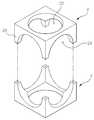
도 1은 본 발명에 따른 유닛의 조립에 의해 단위블럭이 형성되는 분해사시도이고,
도 2는 본 발명에 따른 단위블럭에 보강링이 게재된 상태를 나타내는 사시도이고,
도 3은 본 발명에 따른 유닛의 조립예를 나타내는 측단면도이고,
도 4는 본 발명의 조립식 빗물저류조를 나타내는 사시도이고,
도 5는 본 발명의 일 구성인 보강링의 일 실시 예를 나타내는 측단면도이고,
도 6a 및 도 6b는 도 5에 도시된 보강링의 또 다른 실시 예를 나타내는 각각의 개략도이고,
도 7은 본 발명의 일 구성으로서 여과부를 나타내는 측단면도이고,
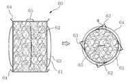
도 8는 도 7에 도시된 여과부가 관부에 장착되는 상태를 나타내는 개략도이고,
도 9a 내지 도 9d는 본 발명에 따른 빗물저류조 시공방법의 일 실시예를 나타내는 개략도이다.1 is an exploded perspective view in which a unit block is formed by assembling a unit according to the present invention,
2 is a perspective view showing a state in which a reinforcing ring is placed on a unit block according to the present invention,
3 is a side sectional view showing an assembling example of the unit according to the present invention,
4 is a perspective view showing the assembled rainwater storage tank of the present invention,
5 is a side sectional view showing an embodiment of a reinforcing ring which is a constitution of the present invention,
Figs. 6A and 6B are respective schematic views showing still another embodiment of the reinforcing ring shown in Fig. 5,
7 is a side sectional view showing a filtration unit as one configuration of the present invention,
8 is a schematic view showing a state in which the filtration part shown in Fig. 7 is mounted on the tube part,
9A to 9D are schematic views showing an embodiment of a rainwater storage tank construction method according to the present invention.
이하, 본 발명의 구성 및 작용을 첨부된 도면에 의거하여 좀 더 구체적으로 설명한다. 본 발명을 설명함에 있어서, 본 명세서 및 청구범위에 사용된 용어나 단어는 발명자가 그 자신의 발명을 가장 최선의 방법으로 설명하기 위해 용어의 개념을 적절하게 정의할 수 있다는 원칙에 입각하여 본 발명의 기술적 사상에 부합하는 의미와 개념으로 해석되어야만 한다.Hereinafter, the structure and operation of the present invention will be described in more detail with reference to the accompanying drawings. In describing the present invention, terms and words used in the present specification and claims are to be construed in accordance with the principles of the present invention, on the basis that the inventor can properly define the concept of a term in order to best explain his invention It should be construed as meaning and concept consistent with the technical idea of.
본 발명에 따른 조립식 빗물저류조(이하, "빗물저류조"라함)는 측면에 반원형의 개구(21)가 형성되어 직경이 좁아드는 4개의 기둥(23)이 형성되고 하면에는 원형의 개구(22)가 형성되는 한쌍의 유닛(2) 간 각각의 기둥이 접하도록 조립되어 3방향의 직교하는 유로(11)가 형성되도록 하는 단위블럭(10)이 종횡으로 적층, 조립됨으로써 완성되는 것으로 우천시 그 내부로 유입되는 빗물을 유로관부(11)에 흐르게 하여 빗물을 저장시키거나 지반으로 침투시키기 위한 것이다.(Hereinafter referred to as "rainwater storage tank") according to the present invention is formed with four
도 1을 참조하여 구체적으로 설명하면, 본 실시 예에 따른 유닛(2)은 측면에 반원형의 개구(21)가 4개 형성되어 직경이 좁아드는 4개의 기둥(23)이 형성되고 하면에는 원형의 개구(22)가 형성됨에 특징이 있다.1, the
상기 4개의 기둥(23)은 각각 하방향 곡면을 형성하는 개구(21)에 의해 연결이 되는데, 이렇게 4개의 기둥(23)이 직경이 좁아들도록 구성되되, 곡면을 형성하면서 상호 연결이 되도록 직경이 좁아들게 형성되어 상재하중에 대해 각각의 기둥(23)이 하중을 완화시켜 전달시키도록 하는 구조를 가지게 되어 구조적으로 안정된 장점이 있다.The four
이러한 한쌍의 유닛(2)이 각각 기둥(21)이 대향하도록 조립이 되어 단위블럭(10)이 형성되는데, 이렇게 형성된 단위블럭에는 도 2에서 보는 바와 같이 직교하는 3개의 유로가 형성되는 것이다.The pair of
또한 도 2에서는 상기 단위블럭(10)에 있어 각각의 유로(11) 단부에 보강링(20)이 게재되도록 하는 예를 제시한다. 이렇게 보강링(20)을 구성하는 이유는 유로(11)에 있어 피복두께가 가장 작아지는 단위블럭(10)의 상,하단과 유로(11)의 산,골부분이 하중에 대해 취약점으로 작용할 수 있는 바, 상기 보강링(20)이 게재됨으로써 이러한 문제를 해결하는 것이다.In addition, FIG. 2 shows an example in which the reinforcing
상기 보강링(20)은 유닛(2)의 제조시 프리캐스트화 할 수 있음은 물론 유닛(2) 간 조립후 부착하도록 구성될 수 있다.The reinforcing
상기 보강링(20)은 재료면에서 부식에 대한 저항성이 우수하고, 무게비 강성이 뛰어나며, 자중이 가벼워 시공이 간편한 재생 플라스틱관 또는 강화 플라스틱관 등의 합성수지재를 사용할 수 있다.The reinforcing
한편, 상기 보강링(20)은 도 5에서 보는 바와 같이 외부에 표피층(28)이 구성되도록 할 수 있는 바, 상기 보강링(20)을 열경화성수지 등 플라스틱재로 구성하되, 그 외주연에 친수성섬유가 와인딩 된 표피층(28)이 형성되도록 하는 것이다.5, the
이렇게 표피층(28)을 구성하는 이유는 역학적인 측면에서 주된 역할을 하도록 하는 것으로 각각의 보강링(20)은 상기 친수성섬유를 고정시켜주면서 한 개의 침수성섬유가 끊어졌을 때 다른 섬유로 하중을 전달하도록 하는 기능을 하는 것이다.The reason why the
특히 상기 표피층(28)이 친수성섬유로 구성되도록 하는 이유는 유닛(2)을 구성하는 콘크리트와 수소결합을 통해 이질의 보강링(20)과 유닛(2)의 부착을 견고히 하기 위한 것이다. 여기서 친수성섬유는 그 종류를 한정하지 않으며 폴리염화비닐 등이 사용될 수 있다.Particularly, the reason why the
이에 더하여 본 발명에서는 도 6a 및 도 6b에서 보는 바와 같이 상기 표피층(28)의 다른 실시 예를 제시한다.In addition, another embodiment of the
도 6a에서는 상기 표피층(28)에 와인딩 된 친수성섬유에 프라이머(283)를 함침하여 입자성분말(281)이 부착되도록 하는 예를 제시하고 있다.6A shows an example in which a hydrophilic fiber wound on the
이와 같이 구성하는 이유는 친수성섬유의 와인딩으로 이루어진 표피층(28)에 입자성분말(281)이 부착되도록 하여 몸체부(30)와 물리적인 부착력을 향상시키기 위한 것이다.The reason for this structure is to improve the physical adhesion force with the body portion 30 by allowing the
이에 더하여 상기 입자성분말(281)은 다공질의 광물입자로 구성되도록 함으로써 유닛(2)과의 부착력에 더해 유닛(2)와 보강링(20) 사이에 단열층이 형성되도록 하는 것이다.In addition to this, the
이와 같이 단열층이 형성되도록 하는 이유는 유닛(2)과 보강링(20)이 이질의 재질로 구성되어 열팽창계수가 다르므로 이렇게 입자성분말(281)에 의해 단열층이 형성되도록 함으로써 열팽창계수의 차이로 인한 재질간 분리, 유닛(2)의 동결융행 방지 등의 기능이 발현되는 것이다.The reason why the heat insulating layer is formed in this manner is that the
여기서 다공질의 광물질은 실리카, 송이 등 그 종류를 한정하지 않는다.The porous mineral is not limited to silica or clay.
다른 예로서 도 6b에서는 상기 표피층(28)에 와인딩 된 친수성섬유에 프라이머(283)를 함침하여 친수성 단섬유(282)가 부착되도록 하는 예를 제시하고 있다.As another example, FIG. 6B shows an example in which the hydrophilic fibers wound on the
이와 같이 표피층(28)에 친수성 단섬유(282)가 돌출되도록 함으로써 유닛(2)에 있어 보강링(20)과 접하는 부위에 온도균열 등을 제어할 수 있도록 하는 것이며, 친수성 단섬유(282)의 수소결합 및 물리적 돌출에 의한 부착력을 강화시킬 수 있게 되는 것이다.The
이 경우도 유닛(2)과 보강링(20)의 부착력 강화에 의해 이질의 재질에 의해 발생될 수 있는 들뜸, 균열 등의 하자를 방지할 수 있게 되는 것이다.In this case also, it is possible to prevent defects such as lifting and cracking which may be caused by the material of the heterogeneous body by strengthening the adhesion between the
도 4에서는 본 발명에 따른 빗물저류조(1)가 조립된 상태를 나타낸 것으로, 본 발명에 따른 빗물저류조(1)가 복수의 단위블럭(10)이 종횡으로 적층, 조립되는 것을 보여준다. 도면에 도시 하지는 않았으나 각 단위블럭(10)간의 결합수단으로는 각 단위블럭(10)에 일체로 체결구를 형성하거나 볼트, 너트와 같은 별도의 체결장치 등 공지의 구성을 사용하면 무방하므로 그 설명을 생략한다.FIG. 4 shows a state in which the
일 예로 도 3에서는 유닛(2) 간 조립의 예를 도시하고 있는 바, 본 실시 예는 유닛(2) 간을 상,하로 적층하여 프리스트레싱에 의해 조립되는 예를 제시하고 있다. 이를 위해서 각 유닛(2)에는 상호 연통되도록 관통공(24)이 형성되고, 각각 관통공(24)을 연통하도록 긴장재(25)를 삽입하여 정착구(26)에 의해 정착이 되도록 한다.For example, FIG. 3 shows an example of assembly between
종횡방향으로 적층, 조립되어 빗물저류조를 구성하게 되는 복수의 단위블럭(10)은 내부의 유로(11)가 상호간에 연통되어 우천시 빗물이 저류될 수 있는 공간이 마련됨은 물론 다방향으로 빗물이 유동하도록 구성되어 지반으로 침투가 가능하게 되는 것이다.The plurality of unit blocks 10, which are stacked and assembled vertically and horizontally to constitute a rainwater storage tank, are provided with a space in which the
한편, 상기와 같이 단위블럭(10)들을 조립하여 형성되는 빗물저류조의 외부에 마감재를 처리할 수 있는데, 상기 마감재는 빗물저류조의 외부를 감싸며 빗물저류조에 저장된 빗물이 외부로 침출될 수 있도록 하는 투수형시트를 사용할 수 있다. 상기 투수형시트는 부직포 등의 재질을 사용하는데, 폐색현상을 방지하기 위해 지반분류에 따라 부직포의 입경을 조절하여 사용하는 것이 바람직하다.Meanwhile, the finishing material can be treated on the outside of the rainwater storage tank formed by assembling the unit blocks 10 as described above. The finishing material covers the outside of the rainwater storage tank, and the rainwater stored in the rainwater storage tank can be leached to the outside. Shaped sheet can be used. The permeable sheet is made of a nonwoven fabric or the like, and it is preferable to adjust the particle diameter of the nonwoven fabric according to the classification of the ground in order to prevent clogging.
여기서 폐색현상이란 흙입자가 흙모체로부터 이탈한 후 부직포의 간극내 유체의 흐름에 의해 이동이 이루어지다가 부직포의 간극을 메우게 되는 현상을 말하는 것으로 이로 인해 부직포의 통수능을 감소시켜 빗물저류조에 저장된 빗물이 지반으로 침출될 수 없게 되는 것을 방지하기 위해 지반분류에 따라 부직포의 입경을 조절하여 사용함이 타당하다.Here, the occlusion phenomenon refers to a phenomenon in which the soil particles are separated from the soil matrix and then moved by the flow of the fluid in the gap of the nonwoven fabric, thereby filling up the gap of the nonwoven fabric. This reduces the watertightness of the nonwoven fabric, It is proper to use the nonwoven fabric by controlling the particle size of the nonwoven fabric according to the classification of the ground in order to prevent it from being leached into the ground.
상기 부직포 등으로 이루어진 투수형시트는 빗물저류조에 저장된 빗물이 지반으로 침출되도록 하는 기능에 더하여 외부로부터 이물질이 빗물저류조 내부로 유입되는 것을 차단하는 기능도 수행하는 것이다.The permeable sheet made of the nonwoven fabric or the like functions not only to allow the rainwater stored in the rainwater storage tank to be leached into the ground but also to prevent the foreign matter from flowing into the rainwater storage vessel from the outside.
한편 상기 마감재는 빗물저류조에 저장된 빗물이 외부로 침출될 수 없도록 하는 차수형시트도 사용할 수 있다. 상기 차수형시트는 EDPM 재질 등으로 구성할 수 있으며, 빗물저류조에 저장된 빗물의 지반 유출 및 외부이물질이 빗물저류조의 내부로의 유입도 차단하는 기능을 수행하는 것으로서 차수형시트를 마감재로 사용하는 경우에는 빗물저류조에 저장된 빗물의 외부유출을 위해 별도의 배수관 등을 설치하는 것이 바람직할 것이다.On the other hand, the finishing material may be a car shape sheet which prevents the rainwater stored in the rainwater storage tank from leaking out. The car shape sheet may be made of EDPM material or the like and functions to prevent the infiltration of groundwater of the rainwater stored in the rainwater storage tank and the inflow of foreign matter into the rainwater storage tank. In case of using the car water- It is desirable to provide a separate drain pipe or the like for the external leakage of the rainwater stored in the rainwater storage tank.
상기와 같이 마감재에 따라 투수형시트를 빗물저류조의 외부에 설치하여 빗물이 지반으로 침출될 수 있도록 구성(이하, 침투형이라함.)할 수 있으며, 빗물의 지반으로의 침출을 차단하고, 상기 저장된 빗물을 타 용도로 사용하기 위해서 빗물저류조의 외부를 차수형시트로 감싸서 빗물을 상기 빗물저류조에 저장할 수 있도록 구성(이하, 차수형이라함.)할 수 있는데, 상기 차수형시트는 저장된 빗물이 외부로 유출됨이 없으므로 빗물의 압력 등에 의해 차수형시트가 손상을 입을 수 있으므로 상기 차수형시트의 내, 외부로 보호용으로 투수용시트를 더 설치하는 것이 바람직하다. 또한 침투형과 상기 차수형을 병용하여 구성(이하, 병용형이라함.)할 수 있다.As described above, the permeable sheet is installed outside the rainwater storage tank according to the finishing material so that the rainwater can be leached into the ground (hereinafter referred to as the infiltration type), and the leaching of the rainwater into the ground is blocked, In order to use the stored rainwater for other purposes, the outside of the rainwater storage tank may be wrapped with a car shape sheet so that rainwater can be stored in the rainwater storage tank (hereinafter referred to as a car shape) It is preferable to further provide a water permeable sheet for protection to the inside and outside of the car shape sheet because the car shape sheet may be damaged by the pressure of rainwater because there is no leakage to the outside. Further, the infiltration type and the differential type can be used together (hereinafter referred to as a combination type).
우선 침투형의 경우 상기 단위블럭(10)을 조립하여 형성된 빗물저류조가 지하로 매립되며, 상기 빗물저류조의 외부에 상기 투수형시트가 시공된다. 상기 빗물저류조의 상부에는 지상과 관통하는 점검구가 하나 이상 구성되며, 상기 점검구의 구성에 의해 사후적으로 상기 빗물저류조 내부를 점검하여 침전된 이물질 등을 제거할 수 있게 되는 것이다. 이경우는 로버트형 카메라 등이 이용될 수 있다.First, in case of the penetration type, the rainwater storage tank formed by assembling the
상기 침투형에 의해 빗물이 저장, 침출되는 과정을 보면 건물 등에 흐르는 빗물이 유입관을 통해 빗물저류조로 유입되며 이렇게 유입되는 빗물은 빗물저류조의 최 외곽에 조립된 단위블럭(10)에 유로(11)를 통해 지반으로 빗물이 침출되어 빗물이 빗물저류조를 범람하여 홍수 등을 유발시킴을 사전에 방지하게 되는 것이다. 상기 침투형은 골프장, 운동장 등 빗물의 저장보다는 빗물을 지반으로의 침출이 중요한 경우에 사용됨이 바람직하다.In the process of storing and leaching rainwater by the penetration type, rainwater flowing into a building or the like flows into the rainwater storage tank through the inflow pipe, and the rainwater flowing into the rainwater storage pool is introduced into the
저장형의 경우도 상기 단위블럭(10)을 조립하여 형성된 빗물저류조가 지하로 매립되며, 상기 빗물저류조의 측면과 밑면에 상기 차수형시트가 시공되며, 상기 차수형시트의 내,외부로 투수형시트를 보호용으로 시공하는 것이 바람직하다.In the case of the storage type, the rainwater storage tank formed by assembling the
이러한 저장형은 상기 빗물저류조에 저장된 빗물을 이용하는데 주목적이 있으므로 배수관이 구성되어야 한다.Since the storage type is mainly used to utilize rainwater stored in the rainwater storage tank, a drain pipe should be constructed.
상기 저장형에 의해 빗물이 저장, 침출되는 과정을 보면 유입관을 통해 빗물이 빗물저류조로 유입되고, 이렇게 유입된 빗물은 빗물저류조의 측면 및 밑면이 상기 차수형시트에 의해 감싸지므로 빗물이 지반으로 침출되지 않고, 다만, 상면에 침투형시트가 설치되므로 상면을 통해서만 상기 빗물저류조를 범람하는 빗물이 침출된다.In the process of storing and leaching rainwater by the storage type, the rainwater flows into the rainwater storage tank through the inflow pipe, and the side and bottom of the rainwater storage tank are enclosed by the carillon- However, since the permeable sheet is provided on the upper surface, the rainwater overflowing the rainwater storage tank is leached only through the upper surface.
상기와 같이 빗물의 침출이 없으므로 상기 차수형시트에 빗물의 압력이 작용하여 하자를 유발할 우려가 있으므로 상기 차수형시트의 안,팍으로 보호용으로 상기 투수형시트을 설치하여 시트의 찢김 등에 의한 빗물의 침출을 방지하는 것이다.Since there is no leaching of rainwater as described above, there is a possibility that the pressure of the rainwater acts on the car shape sheet, which may cause defects. Therefore, the permeable sheet for protecting the car shape sheet is provided to protect the car shape sheet, .
상기와 같이 빗물저류조에 저장된 빗물은 배수관을 통해 다양한 목적에 사용토록 배출되는 것이다. 이렇게 저장된 빗물은 식수, 방화용 등 적절한 용도로 사용하게 되는 것이다.The rainwater stored in the rainwater storage tank is discharged through the water discharge pipe for various purposes. Such stored rainwater will be used for drinking water, fire protection and other purposes.
이러한 저장형의 경우도 점검구를 통해 빗물저류조에 빗물의 저장상태나, 내부하자 유무 점검 및 저장된 빗물로부터 걸어진 이물질의 제거를 할 수 있다.In case of such a storage type, it is also possible to check the storage state of rainwater, the existence of internal defect, and the foreign matter hanged from the stored rainwater through the inspection port.
상기 병용형은 상기 침투형과 상기 저장형을 동시에 사용하는 것으로 상호 보완적으로 사용되는 것이다.The combination type is used complementarily to the simultaneous use of the permeation type and the storage type.
한편 본 발명에서는 도 7에서 여과부(60)를 도시하고 있는데, 빗물저류조(1)를 형성하고 있는 단위블럭(10)에 선택적으로 여과부(60)가 해당 단위블럭(10)에 착탈이 가능하도록 구성하여 빗물저류조(1)에서 초기 우수 등의 경우 여과부(60)가 장착된 단위블럭(10)에 의해 여과가 이루어지도록 하는 것이다.7, the
또한 상기 여과부(60)는 사용중 폐색된 경우 해당 단위블럭(10)으로부터 탈착이 가능하도록 하여 여과부(60) 또는 여재(62)를 교체후 다시 장착이 가능하도록 하는 것이다.In addition, when the
이를 위해 상기 여과부(60)는 도 7에서 보는 바와 같이 여재틀(61), 여재(62) 및 탄성링(63)을 포함하여 구성되도록 한다.7, the
상기 여재틀(61)은 유로(11)의 형상에 따라 원통형으로 구성되며 메쉬망으로 구성되어 내,외부가 연통하도록 하는 구조를 가진다. 상기 여재틀(61)에는 상부에 후크(65)가 형성되어 사용중 여재(62)에 폐색이 발생하는 경우 각종 도구를 이용하여 해당 여과부(60)를 단위블럭(10)으로부터 탈착하도록 하기 위한 구성에 해당한다.The
상기 여재틀(61)은 높이가 각 유로(11)의 직경보다 크게 구성하여 일 유로(11)에는 상,하단이 노출되도록 하고, 타 유로(11)들에는 측면이 노출되도록 한다. 예로 도 8에서 보는 바와 같이 장착시 수직축에 구성된 일 유로(11)에 여재틀(61)의 상,하단부가 위치하도록 하고, 타유로(11)들에 측면이 노출되도록 하는 것이다. 즉 다방향에서 물의 유동에 의해 여과가 이루어지도록 하는 것이다.The
또한 상기 여재틀(61)에는 상,하단에 상향경사구배가 형성된 플랜지(64)가 각각 구성되도록 하는 바, 상기 플랜지(64)는 탄성재질로 구성하여 도 8에서 보는 바와 같이 일 유로(11)에 각각 밀착이 되도록 함으로써 유로(11) 내부의 물이 반드시 여재(62)를 통과하도록 하며 여재틀(61)이 유로(11)에서 견고한 장착이 이루어지도록 하기 위한 것이다.As shown in FIG. 8, the
상기 여재(62)는 그 종류를 한정하지 않으며 상기 여재틀(61)의 메쉬보다 직경이 커서 여재틀(61)에서 외부로 유출되는 것을 방지하여야 하는 것은 당연하다.It is needless to say that the type of the
상기 탄성링(63)은 상기 여과부(60)가 해당 단위블럭(10)에서 장착 및 착탈이 용이하도록 하는 구성으로서 상기 여재틀(61)의 측면에 복수로 돌출되는 링형상의 구성에 해당한다.The
도 7에서는 상기 탄성링(63)이 여재툴(61)의 측면에 4개가 구성된 예를 도시하고 있는데, 상기 탄성링(63)은 여과부(60)의 장착시 상기 여과부(60)가 삽입되는 유로(11)에서는 상기 여재틀(61)에 겹쳐진 상태를 유지하면서 상기 유로(11)의 중앙에서 타 유로(11)의 내부로 펼쳐지면서 상기 여과부(60)를 상기 유로(11)에 장착시키도록 하는 것이다.7 shows an example in which the
즉 도 7에서 보는 바와 같이 각각의 탄성링(63)은 탄성재질에 기해 일 유로(11)에 장착시 여재틀(61)에 겹쳐지는 형상으로 삽입이 되도록 하며 여과부(61)가 일 유로(11) 중앙에 도달시 타 유로(11)로 각각의 탄성링(63)이 펼쳐지면서 여과부(60)가 일 유로(11) 중앙에 장착이 되는 것이다.7, each
또한 여재(62) 폐색시는 반대로 상기 여과부(60)를 빼냄에 따라 상기 탄성링(63)이 상기 여재틀(61)에 겹쳐지면서 탈착이 가능하도록 하는 것이다. 이에 상기 탄성링(63)은 상기 여재틀(61)과 예각(α)을 형성하도록 하여 탄성링(63)이 여재틀(61)에 겹쳐지거나 펼쳐지는 과정에서 그 형상의 손상을 방지하여 용이한 탈부착이 가능하도록 하는 것이 타당하다.In addition, when the
특히 탈착시 후크(65)에 각종 도구를 체결하여 탄성링(63)이 경사진 방향으로 회전을 주면서 빼내는 경우 탈착이 용이하도록 하는 것이다.In particular, when the
한편, 본 발명에서는 조립식 빗물저류조 시공방법에 대해서도 제시하고 있는 바, 본 발명의 시공방법은 터파기 하는 단계(S10); 상기 단위블럭을 적층, 조립하여 조립식 빗물저류조를 시공하는 단계(S20); 를 포함하여 이루어짐을 특징으로 한다.In the meantime, the present invention also discloses a method of constructing a storable rainwater storage tank, wherein the construction method of the present invention comprises: (S20) of stacking and assembling the unit blocks to construct a prefabricated rainwater storage tank; And a control unit.
하나의 예로 상기 S20단계에서 단위블럭을 적층, 조립하되, 중앙부에 단위블럭을 적층, 조립하여 중앙조립체를 시공하고, 상기 중앙조립체와 소정거리 이격된 위치에 수직구 구조물 및 지보재를 시공하며, 상기 중앙조립체와 수직구 구조물 사이에 단위블럭을 적층, 조립하여 외각조립체를 시공하여 조립식 빗물저류조를 시공하도록 할 수 있다. 이와 같은 시공플로우가 도 9a 내지 도 9d에 도시되고 있다.For example, in step S20, unit blocks are stacked and assembled, unit blocks are stacked and assembled at a central portion to construct a center assembly, a straight leg structure and support members are installed at a position spaced apart from the center assembly by a predetermined distance, A unitary block may be stacked and assembled between the central assembly and the vertical structure to construct the outer assembly, thereby constructing the assembled storm water storage tank. Such a construction flow is shown in Figs. 9A to 9D.
즉 본 실시 예에서는 상기 빗물저류조를 시공하는 단계(S20)를 1,2차에 걸친 시공을 하도록 함에 특징이 있는 바, 우선 도 9a에서 보는 바와 같이 중앙부에 단위블럭을 적층, 조립하여 중앙조립체(1-1)를 시공하는 단계를 갖는다.In other words, in the present embodiment, the rainwater storage tank is constructed in such a manner that the step S20 is carried out over the first and second spaces. First, as shown in FIG. 9A, the unit blocks are stacked and assembled at the center, 1-1). ≪ / RTI >
이 경우 굴착된 지반의 측부는 자연토사에 해당하여 중앙부는 토압에 대한 영향이 없는 바, 우선 상기 단위블럭(10)을 적층, 조립하여 중앙조립체(1-1)를 시공한다.In this case, the side portion of the excavated soil corresponds to natural soil, and the central portion does not affect the earth pressure. First, the
그 다음으로 도 9b에서 보는 바와 같이 상기 중앙조립체(1-1)와 소정거리 이격된 위치에 수직구 구조물(3) 및 지보재(g)를 시공하는 단계를 갖는다.Next, as shown in FIG. 9B, there is a step of constructing the straight leg structure 3 and the support material g at a position spaced apart from the center assembly 1-1 by a predetermined distance.
이 경우 수직구 구조물(3)과 중앙조립체(1-1) 사이에만 지보재(g)를 설치하면 되므로 사용 지보재(g)의 양을 줄일 수 있으며, 지보재(g)의 길이를 짧게 할 수 있으므로 지보재(g)의 직경을 작게 하여도 충분한 바 경제적인 시공이 가능하게 되는 것이다.In this case, since the support material g is provided only between the vertical bar structure 3 and the central assembly 1-1, the amount of the used support material g can be reduced and the length of the support material g can be shortened, (g) is made small, economical construction is possible.
또한, 이렇게 지보재(g)를 사용할 수 있으므로 그 해체가 용이하고, 시공안전면에서도 유리하게 되는 것이다.Further, since the support material g can be used in this way, it is easy to disassemble it, and it is also advantageous in terms of construction safety.
그 다음으로 상기 도 9c에서 보는 바와 같이 상기 중앙조립체(1-1)와 수직구 구조물(3) 사이에 단위블럭(10)을 적층, 조립하여 외각조립체(1-2)를 시공하는 단계를 갖는다. 즉 중앙조립체(1-1)와 수직구 구조물(2) 사이에 외각조립체(1-2)를 시공하여 전체 빗물저류조(1)를 완성하게 되는 것이다.Next, as shown in FIG. 9C, there is a step of laminating and assembling the
이때 하부에서부터 지보재(g)를 제거하면서 상기 단위블럭(10)을 적층, 조립하게 되는 바, 기 시공된 중앙조립체(1-1)에 의해서 상기 수직구 구조물(3)로부터의 토압이 지지되므로 전체 구조물의 안정화를 유도할 수 있게 되는 것이다.At this time, the unit blocks 10 are stacked and assembled while removing the support material g from the bottom. Since the earth pressure from the straight-ended structure 3 is supported by the previously installed center assembly 1-1, And stabilization of the structure can be induced.
마지막으로 도 9d에서 보는 바와 같이 마무리 시공을 하는 단계를 갖는 바, 본 단계에서는 수직구 구조물(3)을 제거하고, 전체 빗물저류조를 매립하여 시공을 완성하는 것이다. 또한 경우에 따라 수직구 구조물(3)과 완성된 빗물저류조(1) 사이에 모래 등 충진제를 충진한 후에 매립을 함으로써 시공을 완성할 수 있다.Finally, as shown in FIG. 9 (d), there is a finishing construction step. In this step, the water straight structure 3 is removed and the entire rainwater storage tank is buried to complete the construction. In some cases, it is possible to complete the construction by filling the sandwich structure 3 and the completed
이상 설명한 내용을 통해 당업자라면 본 발명의 기술사상을 일탈하지 아니하는 범위에서 다양한 변경 및 수정 가능함을 알 수 있을 것이다. 따라서, 본 발명의 기술적 범위는 명세서의 상세한 설명에 기재된 내용으로 한정되는 것이 아니라 특허청구범위에 의해 정해져야만 할 것이다.It will be apparent to those skilled in the art that various modifications and variations can be made in the present invention without departing from the spirit or scope of the invention. Therefore, the technical scope of the present invention should not be limited to the contents described in the detailed description of the specification, but should be defined by the claims.
1 : 빗물저류조2 : 유닛
10 : 단위블럭20 : 보강링
1: Rainwater storage tank 2: Unit
10: unit block 20: reinforcing ring
Claims (8)
Translated fromKorean상기 단위블럭은,
측면에 반원형의 개구가 형성되어 직경이 좁아드는 4개의 기둥이 형성되고 하면에는 원형의 개구가 형성되는 한쌍의 유닛 간 각각의 기둥이 접하도록 조립되어 3방향의 직교하는 유로가 형성되며,
상기 단위블럭에는
상기 일 유로의 중앙에 여과부가 착탈이 되도록 구성되되,
상기 여과부는, 메쉬망으로 구성되는 여재틀과 상기 여재틀에 충진되는 여재와, 상기 여재틀의 중앙부에는 상기 여과부가 삽입되는 일 유로에서는 상기 여재틀에 겹쳐진 상태를 유지하면서 일 유로의 중앙에서 타 유로의 내부로 펼쳐지면서 상기 여과부를 상기 단위블럭에 장착시키는 복수의 탄성링으로 구성됨을 특징으로 하는 조립식 빗물저류조.
1. A rainwater storage tank in which a plurality of unit blocks are stacked and assembled,
The unit block includes:
Four columns are formed on the side surface with a semicircular opening formed therebetween and a pair of units each having a circular opening are formed on the lower surface thereof so that the columns are in contact with each other so as to form orthogonal flow paths in three directions,
In the unit block,
Wherein the filtration unit is detachably attached to the center of the one flow path,
The filter unit may include a filter medium frame formed of a mesh net, a filter medium filled in the filter medium frame, and a filter unit disposed in the center of the filter medium unit, And a plurality of elastic rings extending to the inside of the flow path and mounting the filtration unit to the unit block.
상기 단위블럭의 각각 유로에는 끝단의 내주연에 보강링이 구성됨을 특징으로 하는 조립식 빗물저류조.
The method according to claim 1,
Wherein each channel of the unit block has a reinforcing ring at an inner periphery of an end thereof.
상기 보강링은 그 외주연에 친수성섬유가 와인딩 되어 부착된 표피층이 구성됨을 특징으로 하는 조립식 빗물저류조.
3. The method of claim 2,
Wherein the reinforcing ring comprises a skin layer on which a hydrophilic fiber is wound and attached to the outer periphery.
상기 표피층에는 와인딩 된 친수성섬유에 프라이머를 함침하여 입자성분말 또는 친수성 단섬유가 부착되는 것을 특징으로 하는 조립식 빗물저조류.
5. The method of claim 4,
Wherein the skin layer is impregnated with a primer to the wound hydrophilic fiber to attach a particle component or a hydrophilic staple fiber to the skin layer.
상기 입자성분말은 다공질의 광물입자인 것을 특징으로 하는 조립식 빗물저류조.
6. The method of claim 5,
Wherein the particle component horse is a porous mineral particle.
제 1항, 제2항, 제 4항 내지 제 6항 중 어느 한 항의 단위블럭을 적층, 조립하여 조립식 빗물저류조를 시공하는 단계(S20);
를 포함하여 이루어짐을 특징으로 하는 조립식 빗물저류조 시공방법.
(S10);
(S20) of stacking and assembling the unit blocks according to any one of claims 1, 2, and 6 to construct a prefabricated rainwater storage tank;
Wherein the rainwater is discharged from the rainwater storage tank.
상기 S20단계에서 단위블럭을 적층, 조립하되,
중앙부에 단위블럭을 적층, 조립하여 중앙조립체를 시공하고, 상기 중앙조립체와 소정거리 이격된 위치에 수직구 구조물 및 지보재를 시공하며, 상기 중앙조립체와 수직구 구조물 사이에 단위블럭을 적층, 조립하여 외각조립체를 시공하여 조립식 빗물저류조를 시공하는 것을 특징으로 하는 조립식 빗물저류조의 시공방법.
8. The method of claim 7,
In step S20, unit blocks are stacked and assembled,
A unit block is stacked and assembled at a central portion to construct a center assembly, a straight leg structure and a support material are installed at a predetermined distance from the center assembly, and unit blocks are stacked and assembled between the center assembly and the straight leg structure Wherein the assembly of the rainwater storage tank is performed by installing the outer assembly.
Priority Applications (1)
| Application Number | Priority Date | Filing Date | Title |
|---|---|---|---|
| KR1020140181731AKR101525778B1 (en) | 2014-12-16 | 2014-12-16 | A prefabricated rainwater storage tank and construction method thereof |
Applications Claiming Priority (1)
| Application Number | Priority Date | Filing Date | Title |
|---|---|---|---|
| KR1020140181731AKR101525778B1 (en) | 2014-12-16 | 2014-12-16 | A prefabricated rainwater storage tank and construction method thereof |
Publications (1)
| Publication Number | Publication Date |
|---|---|
| KR101525778B1true KR101525778B1 (en) | 2015-06-05 |
Family
ID=53500065
Family Applications (1)
| Application Number | Title | Priority Date | Filing Date |
|---|---|---|---|
| KR1020140181731AActiveKR101525778B1 (en) | 2014-12-16 | 2014-12-16 | A prefabricated rainwater storage tank and construction method thereof |
Country Status (1)
| Country | Link |
|---|---|
| KR (1) | KR101525778B1 (en) |
Cited By (1)
| Publication number | Priority date | Publication date | Assignee | Title |
|---|---|---|---|---|
| CN112343159A (en)* | 2020-10-30 | 2021-02-09 | 深圳市新绿园林工程有限公司 | Environment-friendly municipal administration inspection shaft waste fitting discharging |
Citations (4)
| Publication number | Priority date | Publication date | Assignee | Title |
|---|---|---|---|---|
| KR950033755U (en)* | 1994-05-31 | 1995-12-18 | 대광콘크리트 주식회사 | Concrete fume pipe with reinforcing ring for socket |
| KR101052857B1 (en)* | 2010-11-25 | 2011-07-29 | 산수산업 (주) | Rainwater storage tank construction method using rainwater storage tank and rainwater storage tank and rainwater storage tank |
| KR101141308B1 (en)* | 2011-06-30 | 2012-07-11 | 이상우 | Permeatable rain storage system |
| KR20140022703A (en)* | 2012-08-14 | 2014-02-25 | 주식회사 서영엔지니어링 | Hexa-tube blocks for rainwater storage and the construction method using the same |
- 2014
- 2014-12-16KRKR1020140181731Apatent/KR101525778B1/enactiveActive
Patent Citations (4)
| Publication number | Priority date | Publication date | Assignee | Title |
|---|---|---|---|---|
| KR950033755U (en)* | 1994-05-31 | 1995-12-18 | 대광콘크리트 주식회사 | Concrete fume pipe with reinforcing ring for socket |
| KR101052857B1 (en)* | 2010-11-25 | 2011-07-29 | 산수산업 (주) | Rainwater storage tank construction method using rainwater storage tank and rainwater storage tank and rainwater storage tank |
| KR101141308B1 (en)* | 2011-06-30 | 2012-07-11 | 이상우 | Permeatable rain storage system |
| KR20140022703A (en)* | 2012-08-14 | 2014-02-25 | 주식회사 서영엔지니어링 | Hexa-tube blocks for rainwater storage and the construction method using the same |
Cited By (1)
| Publication number | Priority date | Publication date | Assignee | Title |
|---|---|---|---|---|
| CN112343159A (en)* | 2020-10-30 | 2021-02-09 | 深圳市新绿园林工程有限公司 | Environment-friendly municipal administration inspection shaft waste fitting discharging |
Similar Documents
| Publication | Publication Date | Title |
|---|---|---|
| TWI542758B (en) | Module and assembly for managing the flow of water beneath a ground surface | |
| JP3802027B2 (en) | Combined rainwater temporary storage tank | |
| JP5117932B2 (en) | Underground storage infiltration tank | |
| US8028713B2 (en) | Underground water storage tank | |
| JP3660917B2 (en) | Facility for storing and / or infiltrating rainwater etc. and filling member used for this facility | |
| KR101525778B1 (en) | A prefabricated rainwater storage tank and construction method thereof | |
| JP4517207B2 (en) | Construction for storage and infiltration of rainwater, etc. | |
| JP4993502B2 (en) | Rainwater storage system and drain unit | |
| JP2004052243A (en) | Storage and/or permeation facility for rainwater or the like | |
| KR200433220Y1 (en) | Sump structure | |
| KR101411989B1 (en) | A prefabricated rainwater storage tank and Structure construction method thereof | |
| KR20130045027A (en) | Block type rain retaining facility | |
| JP2011006857A (en) | Structure for temporarily storing drainage and infiltrating drainage to the underground | |
| KR20170136420A (en) | The retaining wall using pile | |
| KR100663793B1 (en) | Prefabricated rainwater storage facility and its construction method | |
| KR100663798B1 (en) | Prefabricated rainwater storage facility that can be assembled by manual and its construction method | |
| KR101099777B1 (en) | Prefab Rainwater Storage Facility | |
| KR102571761B1 (en) | Rainwater storage facility with improved structure | |
| JP2005179919A (en) | Facility for storage and percolation of rainwater and the like | |
| JP2003278193A (en) | Underground water storage tank | |
| KR100736157B1 (en) | Prefabricated rainwater storage facility using pipe unit and construction method | |
| KR101857595B1 (en) | Rain Water Storage Cell Of Improved Capacity And Coupling Structure Thereof | |
| JP3556784B2 (en) | Stacking members used for underground water storage tanks, etc. | |
| WO2022249501A1 (en) | Rainwater storage and infiltration facility and sedimentation retaining board for rainwater storage and infiltration facility | |
| KR200403791Y1 (en) | Jointed facilities keeping rainwater using pipe unit |
Legal Events
| Date | Code | Title | Description |
|---|---|---|---|
| PA0109 | Patent application | Patent event code:PA01091R01D Comment text:Patent Application Patent event date:20141216 | |
| PA0201 | Request for examination | ||
| PA0302 | Request for accelerated examination | Patent event date:20141219 Patent event code:PA03022R01D Comment text:Request for Accelerated Examination Patent event date:20141216 Patent event code:PA03021R01I Comment text:Patent Application | |
| PE0902 | Notice of grounds for rejection | Comment text:Notification of reason for refusal Patent event date:20150120 Patent event code:PE09021S01D | |
| PE0701 | Decision of registration | Patent event code:PE07011S01D Comment text:Decision to Grant Registration Patent event date:20150305 | |
| GRNT | Written decision to grant | ||
| PR0701 | Registration of establishment | Comment text:Registration of Establishment Patent event date:20150529 Patent event code:PR07011E01D | |
| PR1002 | Payment of registration fee | Payment date:20150601 End annual number:3 Start annual number:1 | |
| PG1601 | Publication of registration | ||
| FPAY | Annual fee payment | Payment date:20180529 Year of fee payment:4 | |
| PR1001 | Payment of annual fee | Payment date:20180529 Start annual number:4 End annual number:4 | |
| FPAY | Annual fee payment | Payment date:20190502 Year of fee payment:5 | |
| PR1001 | Payment of annual fee | Payment date:20190502 Start annual number:5 End annual number:5 | |
| PR1001 | Payment of annual fee | Payment date:20200428 Start annual number:6 End annual number:6 | |
| PR1001 | Payment of annual fee | Payment date:20210401 Start annual number:7 End annual number:7 | |
| PR1001 | Payment of annual fee | Payment date:20230403 Start annual number:9 End annual number:9 | |
| PR1001 | Payment of annual fee | Payment date:20240404 Start annual number:10 End annual number:10 | |
| PR1001 | Payment of annual fee | Payment date:20250512 Start annual number:11 End annual number:11 |