KR101525645B1 - Multilayer ceramic capacitor - Google Patents
Multilayer ceramic capacitorDownload PDFInfo
- Publication number
- KR101525645B1 KR101525645B1KR1020110088996AKR20110088996AKR101525645B1KR 101525645 B1KR101525645 B1KR 101525645B1KR 1020110088996 AKR1020110088996 AKR 1020110088996AKR 20110088996 AKR20110088996 AKR 20110088996AKR 101525645 B1KR101525645 B1KR 101525645B1
- Authority
- KR
- South Korea
- Prior art keywords
- ceramic body
- internal electrode
- exposed
- internal
- lead portion
- Prior art date
- Legal status (The legal status is an assumption and is not a legal conclusion. Google has not performed a legal analysis and makes no representation as to the accuracy of the status listed.)
- Expired - Fee Related
Links
Images


Classifications
- H—ELECTRICITY
- H01—ELECTRIC ELEMENTS
- H01G—CAPACITORS; CAPACITORS, RECTIFIERS, DETECTORS, SWITCHING DEVICES, LIGHT-SENSITIVE OR TEMPERATURE-SENSITIVE DEVICES OF THE ELECTROLYTIC TYPE
- H01G4/00—Fixed capacitors; Processes of their manufacture
- H01G4/002—Details
- H01G4/005—Electrodes
- H01G4/012—Form of non-self-supporting electrodes
- H—ELECTRICITY
- H01—ELECTRIC ELEMENTS
- H01G—CAPACITORS; CAPACITORS, RECTIFIERS, DETECTORS, SWITCHING DEVICES, LIGHT-SENSITIVE OR TEMPERATURE-SENSITIVE DEVICES OF THE ELECTROLYTIC TYPE
- H01G4/00—Fixed capacitors; Processes of their manufacture
- H01G4/002—Details
- H01G4/018—Dielectrics
- H01G4/06—Solid dielectrics
- H01G4/08—Inorganic dielectrics
- H01G4/12—Ceramic dielectrics
- H—ELECTRICITY
- H01—ELECTRIC ELEMENTS
- H01G—CAPACITORS; CAPACITORS, RECTIFIERS, DETECTORS, SWITCHING DEVICES, LIGHT-SENSITIVE OR TEMPERATURE-SENSITIVE DEVICES OF THE ELECTROLYTIC TYPE
- H01G4/00—Fixed capacitors; Processes of their manufacture
- H01G4/002—Details
- H01G4/228—Terminals
- H01G4/232—Terminals electrically connecting two or more layers of a stacked or rolled capacitor
- H—ELECTRICITY
- H01—ELECTRIC ELEMENTS
- H01G—CAPACITORS; CAPACITORS, RECTIFIERS, DETECTORS, SWITCHING DEVICES, LIGHT-SENSITIVE OR TEMPERATURE-SENSITIVE DEVICES OF THE ELECTROLYTIC TYPE
- H01G4/00—Fixed capacitors; Processes of their manufacture
- H01G4/002—Details
- H01G4/228—Terminals
- H01G4/236—Terminals leading through the housing, i.e. lead-through
- H—ELECTRICITY
- H01—ELECTRIC ELEMENTS
- H01G—CAPACITORS; CAPACITORS, RECTIFIERS, DETECTORS, SWITCHING DEVICES, LIGHT-SENSITIVE OR TEMPERATURE-SENSITIVE DEVICES OF THE ELECTROLYTIC TYPE
- H01G4/00—Fixed capacitors; Processes of their manufacture
- H01G4/30—Stacked capacitors
Landscapes
- Engineering & Computer Science (AREA)
- Power Engineering (AREA)
- Manufacturing & Machinery (AREA)
- Microelectronics & Electronic Packaging (AREA)
- Chemical & Material Sciences (AREA)
- Ceramic Engineering (AREA)
- Inorganic Chemistry (AREA)
- Fixed Capacitors And Capacitor Manufacturing Machines (AREA)
- Ceramic Capacitors (AREA)
Abstract
Translated fromKoreanDescription
Translated fromKorean본 발명은 적층 세라믹 커패시터에 관한 것으로, 보다 상세하게는 우수한 정전용량을 가지고, 낮은 등가직렬인덕턴스를 나타내는 적층 세라믹 커패시터에 관한 것이다.The present invention relates to a multilayer ceramic capacitor, and more particularly, to a multilayer ceramic capacitor having an excellent capacitance and exhibiting a low equivalent series inductance.
일반적으로 커패시터, 인턱터, 압전체 소자, 바리스터 또는 서미스터 등의 세라믹 재료를 사용하는 전자부품은 세라믹 재료로 이루어진 세라믹 본체, 본체 내부에 형성된 내부전극 및 상기 내부전극과 접속되도록 세라믹 본체 표면에 설치된 외부전극을 구비한다.
In general, an electronic component using a ceramic material such as a capacitor, an inductor, a piezoelectric element, a varistor or a thermistor includes a ceramic body made of a ceramic material, internal electrodes formed inside the body, and external electrodes provided on the surface of the ceramic body to be connected to the internal electrodes Respectively.
세라믹 전자부품 중 적층 세라믹 커패시터는 적층된 복수의 유전체층, 일 유전체층을 사이에 두고 대향 배치되는 내부전극, 상기 내부전극에 전기적으로 접속된 외부전극을 포함한다.A multilayer ceramic capacitor in a ceramic electronic device includes a plurality of laminated dielectric layers, an inner electrode disposed opposite to the dielectric layer with one dielectric layer interposed therebetween, and an outer electrode electrically connected to the inner electrode.
적층 세라믹 커패시터는 소형이면서도 고용량이 보장되고 실장이 용이하다는 장점으로 인하여 컴퓨터, PDA, 휴대폰 등의 이동 통신장치의 부품으로서 널리 사용되고 있다.The multilayer ceramic capacitor is widely used as a component of a mobile communication device such as a computer, a PDA, and a mobile phone due to its small size, high capacity, and ease of mounting.
최근에는 전자제품이 소형화 및 다기능화됨에 따라 칩 부품 또한 소형화 및 고기능화되는 추세이므로, 적층 세라믹 커패시터도 크기가 작고, 용량이 큰 고용량 제품이 요구되고 있다.In recent years, miniaturization and multifunctionalization of electronic products have led to the tendency of miniaturization and high functioning of chip components. Therefore, a multilayer ceramic capacitor is required to have a small-sized and high capacity high-capacity product.
또한, 적층 세라믹 커패시터는 LSI의 전원 회로 내에 배치되는 바이패스(bypass) 커패시터로 유용하게 사용되고 있으며, 이러한 바이패스 커패시터로 기능하기 위해서는 적층 세라믹 커패시터가 고주파 노이즈를 효과적으로 제거할 수 있어야 한다. 이러한 요구는 전자장치의 고주파화 경향에 따라 더욱 증가되고 있다. 바이패스 커패시터로 사용되는 적층 세라믹 커패시터는 회로기판 상의 실장 패드 상에 솔더링을 통하여 전기적으로 연결되며 상기 실장 패드는 기판 상의 배선 패턴이나 도전성 비아를 통해 다른 외부 회로와 연결될 수 있다.In addition, the multilayer ceramic capacitor is usefully used as a bypass capacitor disposed in the power circuit of the LSI. In order to function as a bypass capacitor, the multilayer ceramic capacitor must be capable of effectively removing high frequency noise. Such a demand is further increased in accordance with a tendency toward high frequency of electronic devices. A multilayer ceramic capacitor used as a bypass capacitor is electrically connected to a mounting pad on a circuit board through soldering, and the mounting pad can be connected to another external circuit through a wiring pattern or a conductive via on the substrate.
적층 세라믹 커패시터는 커패시턴스 성분 외에 등가직렬저항(ESR) 및 등가직렬인덕턴스(ESL) 성분을 함께 가지며, 이러한 등가직렬저항(ESR) 및 등가직렬인덕턴스(ESL) 성분은 바이패스 커패시터의 기능을 저해하게 된다. 특히, 등가직렬인덕턴스(ESL)는 고주파에서 커패시터의 인던턴스를 높여 고주파 노이즈 제거 특성을 저해하게 된다.Multilayer ceramic capacitors have both an equivalent series resistance (ESR) and an equivalent series inductance (ESL) component in addition to a capacitance component, and these equivalent series resistance (ESR) and equivalent series inductance (ESL) components impair the function of the bypass capacitor . In particular, the equivalent series inductance (ESL) increases the capacitance of the capacitor at high frequency, thereby hindering the high frequency noise removing characteristic.
본 발명은 우수한 정전용량을 가지고, 낮은 등가직렬인덕턴스를 나타내는 적층 세라믹 커패시터를 제공하는 것을 목적으로 한다.It is an object of the present invention to provide a multilayer ceramic capacitor having an excellent capacitance and exhibiting a low equivalent series inductance.
본 발명의 일 실시형태는 세라믹 소체; 상기 세라믹 소체의 내부에 형성되며, 상기 세라믹 소체의 제1면으로 노출되고, 상기 제1면으로 노출된 영역 중 일부가 서로 중첩되는 인출부를 가지는 제1 및 제2 내부전극; 상기 세라믹 소체의 제1면에 형성되며, 상기 인출부와 각각 연결되는 외부전극; 및 상기 세라믹 소체의 제1면, 상기 제1면과 연결된 제3면 및 제4면에 형성되는 절연층;을 포함하고, 상기 인출부는 세라믹 소체의 제3면 또는 제4면과 소정의 간격을 두고 형성되는 적층 세라믹 커패시터를 제공한다.One embodiment of the present invention relates to a ceramic body; First and second internal electrodes formed in the ceramic body and having a lead portion exposed at a first surface of the ceramic body and partially overlapping with the exposed portions of the first surface; An outer electrode formed on a first surface of the ceramic body and connected to the lead portion; And an insulating layer formed on a first surface of the ceramic body, a third surface connected to the first surface, and a fourth surface, and the lead portion is spaced apart from the third surface or the fourth surface of the ceramic body by a predetermined distance A multilayer ceramic capacitor is provided.
상기 제1 내부전극은 서로 소정의 간격을 두고 상기 세라믹 소체의 제1 면으로 노출되는 제1 및 제2 인출부를 가지고, 상기 제1 인출부는 상기 세라믹 소체의 제3면과 소정의 간격을 두고 형성되고, 상기 제2 인출부는 상기 세라믹 소체의 제4면과 소정의 간격을 두고 형성될 수 있다.Wherein the first internal electrode has first and second lead portions exposed at a first surface of the ceramic body at a predetermined interval from each other, and the first lead portion is formed at a predetermined interval from the third surface of the ceramic body And the second lead portion may be formed at a predetermined distance from the fourth surface of the ceramic body.
상기 제2 내부전극은 상기 세라믹 소체의 제3면 및 제4면과 소정의 간격을 두고 형성되는 제1 인출부를 가질 수 있다.The second internal electrode may have a first lead portion formed at a predetermined interval from the third and fourth surfaces of the ceramic body.
상기 제1 및 제2 내부전극의 단부는 상기 세라믹 소체의 제3면 및 제4면으로 노출될 수 있다.The ends of the first and second internal electrodes may be exposed to the third and fourth surfaces of the ceramic body.
상기 제1 및 제2 내부전극은 세라믹 소체의 실장면에 대하여 수직으로 배치될 수 있다.The first and second internal electrodes may be disposed perpendicular to the mounting surface of the ceramic body.
상기 절연층은 세라믹 슬러리로 형성될 수 있다.The insulating layer may be formed of a ceramic slurry.
상기 외부전극은 상기 제1 및 제2 내부전극의 인출부 중 서로 중첩되지 않는 영역과 연결될 수 있다.The external electrodes may be connected to regions of the lead portions of the first and second internal electrodes that are not overlapped with each other.
상기 세라믹 소체의 제1면에 형성되는 절연층은 제1 및 제2 내부전극의 인출부 중 서로 중첩되는 영역을 모두 덮도록 형성될 수 있다.The insulating layer formed on the first surface of the ceramic body may be formed so as to cover all the overlapping regions of the lead portions of the first and second internal electrodes.
상기 세라믹 소체의 제3면 또는 제4면에 형성되는 절연층은 상기 세라믹 소체의 제3면 또는 제4면으로 노출되는 유전체층과 연결될 수 있다.An insulating layer formed on a third surface or a fourth surface of the ceramic body may be connected to a dielectric layer exposed on a third surface or a fourth surface of the ceramic body.
상기 세라믹 소체의 제1면에 형성되는 절연층은 상기 세라믹 소체의 제1면으로부터 측정되는 제1 및 제2 외부전극의 높이보다 작게 형성될 수 있다.The insulating layer formed on the first surface of the ceramic body may be formed to be smaller than the height of the first and second external electrodes measured from the first surface of the ceramic body.
상기 제1 및 제2 내부전극은 상기 세라믹 소체의 제1면과 대향하는 제2면으로 각각 노출되는 인출부를 가질 수 있다.The first and second internal electrodes may have lead portions exposed to a first surface of the ceramic body and a second surface facing the first surface, respectively.
상기 제1 내부전극은 서로 소정의 간격을 두고 상기 세라믹 소체의 제2 면으로 노출되는 제3 및 제4 인출부를 가지고, 상기 제3 인출부는 상기 세라믹 소체의 제3면과 소정의 간격을 두고 형성되고, 상기 제4 인출부는 상기 세라믹 소체의 제4면과 소정의 간격을 두고 형성될 수 있다.Wherein the first internal electrode has third and fourth lead portions exposed at a second surface of the ceramic body at a predetermined interval from each other and the third lead portion is formed at a predetermined distance from the third surface of the ceramic body And the fourth lead portion may be formed at a predetermined distance from the fourth surface of the ceramic body.
상기 제2 내부전극은 상기 세라믹 소체의 제2면으로 노출되며, 상기 세라믹 소체의 제3면 및 제4면과 소정의 간격을 두고 형성되는 제2 인출부를 가질 수 있다.The second internal electrode is exposed to the second surface of the ceramic body and may have a second lead-out portion formed at a predetermined interval from the third surface and the fourth surface of the ceramic body.
본 발명의 일 실시형태에 따르면, 내부전극은 세라믹 소체의 유전체층에 최소한의 마진부 또는 갭을 남기고, 최대한 넓은 면적으로 형성될 수 있다. 이에 따라, 제1 및 제2 내부전극의 중첩 영역이 넓어져 고용량의 적층 세라믹 커패시터를 형성할 수 있다.According to one embodiment of the present invention, the internal electrode can be formed as wide as possible, leaving a minimum margin or gap in the dielectric layer of the ceramic body. As a result, the overlap region of the first and second internal electrodes is widened, and a high-capacity multilayer ceramic capacitor can be formed.
본 발명의 일 실시형태에 따르면, 제1 및 제2 내부전극은 인출부에도 중첩 영역이 형성되어 적층 세라믹 커패시터의 용량이 증가될 수 있다.According to an embodiment of the present invention, the first and second internal electrodes may also have overlapping regions in the lead-out portions so that the capacity of the multilayer ceramic capacitor can be increased.
또한, 외부 극성이 인가되는 제1 및 제2 내부전극 간의 거리가 가까워져 커런트 루프(current loop)가 짧아질 수 있고, 이에 따라 등가직렬인덕턴스(ESL, Equivalent Series Inductance)가 낮아질 수 있다.In addition, the distance between the first and second internal electrodes to which the external polarity is applied is shortened, so that the current loop can be shortened, and the equivalent series inductance (ESL) can be lowered.
본 발명의 일 실시형태에 따르면, 세라믹 소체에 형성되는 절연층은 세라믹 소체의 일면으로 노출되는 제1 및 제2 내부전극의 단부, 제1 및 제2 내부전극의 인출부를 덮어 내부전극 간의 단락을 방지하고, 내습 특성 저하 등의 내부결함을 방지할 수 있다.According to one embodiment of the present invention, the insulating layer formed on the ceramic body is provided with the end portions of the first and second internal electrodes exposed at one surface of the ceramic body, the lead portions of the first and second internal electrodes, It is possible to prevent internal defects such as deterioration of moisture resistance and the like.
본 발명의 일 실시형태에 따르면 절연층은 내부전극이 형성된 유전체층의 일부와 연결될 수 있고, 이에 따라 절연층과 세라믹 소체의 결합 강도가 향상될 수 있다.According to an embodiment of the present invention, the insulating layer can be connected to a part of the dielectric layer having the internal electrode formed thereon, thereby improving the bonding strength between the insulating layer and the ceramic body.
본 발명의 일 실시형태에 따르면, 절연층의 높이가 조절될 수 있고, 절연층의 높이를 제1 및 제2 외부전극의 높이보다 낮게 형성하는 경우 적층 세라믹 커패시터가 회로 기판 상에 보다 안정적으로 실장될 수 있다.According to one embodiment of the present invention, when the height of the insulating layer can be adjusted and the height of the insulating layer is formed lower than the height of the first and second external electrodes, the multilayer ceramic capacitor is more reliably mounted on the circuit board .
본 발명의 일 실시형태에 따르면, 적층 세라믹 커패시터의 전류의 흐름은 복수 개의 외부전극을 통하여 내부전극으로 전달될 수 있고, 이에 따라 적층 세라믹 커패시터의 커패시턴스 성분에 직렬로 연결되는 인덕턴스의 성분의 크기를 매우 작게 할 수 있다.According to an embodiment of the present invention, the current flow of the multilayer ceramic capacitor can be transmitted to the internal electrode through the plurality of external electrodes, and thus the magnitude of the component of the inductance connected in series to the capacitance component of the multilayer ceramic capacitor Can be made very small.
도 1는 본 발명의 일 실시형태에 따른 적층 세라믹 커패시터를 나타내는 개략적인 사시도이다.
도 2는 도 1에 도시된 적층 세라믹 커패시터의 내부전극 구조를 나타내는 단면도이다.
도 3은 도 1에 도시된 적층 세라믹 커패시터의 제조공정 중 일부 공정을 나타내는 개략적인 상부 평면면도이다.
도 4는 도 1의 A-A'선에 따른 단면도이다.
도 5는 본 발명의 다른 실시형태에 따른 적층 세라믹 커패시터를 나타내는 단면도이다.
도 6은 본 발명의 일 실시형태에 따른 적층 세라믹 커패시터를 나타내는 개략적인 사시도이다.
도 7은 도 6에 도시된 적층 세라믹 커패시터의 내부전극 구조를 나타내는 단면도이다.
도 8는 도 6에 도시된 적층 세라믹 커패시터의 제조공정 중 일부 공정을 나타내는 개략적인 상부 평면면도이다.
도 9는 도 6에 도시된 적층 세라믹 커패시터의 단면도이다.1 is a schematic perspective view showing a multilayer ceramic capacitor according to an embodiment of the present invention.
2 is a cross-sectional view showing an internal electrode structure of the multilayer ceramic capacitor shown in FIG.
FIG. 3 is a schematic top plan view showing some steps of the manufacturing process of the multilayer ceramic capacitor shown in FIG. 1; FIG.
4 is a cross-sectional view taken along the line A-A 'in Fig.
5 is a cross-sectional view showing a multilayer ceramic capacitor according to another embodiment of the present invention.
6 is a schematic perspective view showing a multilayer ceramic capacitor according to an embodiment of the present invention.
7 is a cross-sectional view showing the internal electrode structure of the multilayer ceramic capacitor shown in FIG.
8 is a schematic top plan view showing some steps of the manufacturing process of the multilayer ceramic capacitor shown in Fig.
9 is a cross-sectional view of the multilayer ceramic capacitor shown in Fig.
이하, 첨부된 도면을 참조하여 본 발명의 바람직한 실시형태들을 설명한다. 다만, 본 발명의 실시형태는 여러 가지 다른 형태로 변형될 수 있으며, 본 발명의 범위가 이하 설명하는 실시형태로 한정되는 것은 아니다. 또한, 본 발명의 실시형태는 당업계에서 평균적인 지식을 가진 자에게 본 발명을 더욱 완전하게 설명하기 위해서 제공되는 것이다. 따라서, 도면에서의 요소들의 형상 및 크기 등은 보다 명확한 설명을 위해 과장될 수 있으며, 도면상의 동일한 부호로 표시되는 요소는 동일한 요소이다.
Hereinafter, preferred embodiments of the present invention will be described with reference to the accompanying drawings. However, the embodiments of the present invention may be modified into various other forms, and the scope of the present invention is not limited to the embodiments described below. Furthermore, embodiments of the present invention are provided to more fully explain the present invention to those skilled in the art. Accordingly, the shapes and sizes of the elements in the drawings may be exaggerated for clarity of description, and the elements denoted by the same reference numerals in the drawings are the same elements.
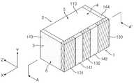
도 1는 본 발명의 일 실시형태에 따른 적층 세라믹 커패시터를 나타내는 개략적인 사시도이고, 도 2는 도 1에 도시된 적층 세라믹 커패시터의 내부전극 구조를 나타내는 단면도이다. 도 3은 도 1에 도시된 적층 세라믹 커패시터의 제조공정 중 일부 공정을 나타내는 개략적인 상부 평면면도이다. 도 4는 도 1의 A-A'선에 따른 단면도이다.
FIG. 1 is a schematic perspective view showing a multilayer ceramic capacitor according to an embodiment of the present invention, and FIG. 2 is a cross-sectional view showing an internal electrode structure of the multilayer ceramic capacitor shown in FIG. FIG. 3 is a schematic top plan view showing some steps of the manufacturing process of the multilayer ceramic capacitor shown in FIG. 1; FIG. 4 is a cross-sectional view taken along the line A-A 'in Fig.
본 실시형태에 따른 적층 세라믹 커패시터는 3단자 수직 적층형 커패시터일 수 있다. “수직 적층형(vertically laminated or vertical multilayer)”은 커패시터 내의 적층된 내부전극이 회로기판의 실장 영역 면에 수직으로 배치되는 것을 의미하고, “3단자(3-terminal)”는 커패시터의 단자로서 3개의 단자가 회로기판에 접속됨을 의미한다.
The multilayer ceramic capacitor according to the present embodiment may be a three-terminal vertical stacked capacitor. The term " vertically laminated or vertical multilayer " means that the stacked internal electrodes in the capacitor are disposed perpendicular to the mounting area of the circuit board, and " 3-terminal " Terminal is connected to the circuit board.
도 1 내지 도 4를 참조하면, 본 실시 형태에 따른 적층 세라믹 커패시터는 세라믹 소체(110); 상기 세라믹 소체의 내부에 형성되는 내부전극(121, 122); 상기 세라믹 소체의 일면에 각각 형성되는 절연층(141, 142, 143, 144) 및 외부전극(131, 132, 133)을 포함할 수 있다.
1 to 4, the multilayer ceramic capacitor according to the present embodiment includes a
본 실시형태에서, 세라믹 소체(110)는 서로 대향하는 제1면(1) 및 제2면(2)과 상기 제1면 및 제2면을 연결하는 제3면(3), 제4면(4), 제5면 및 제6면(6)을 가질 수 있다. 상기 세라믹 소체(110)의 형상에 특별히 제한은 없지만, 도시된 바와 같이 제1면 내지 제6면을 가지는 육면체 형상일 수 있다. 본 발명의 일 실시형태에 따르면, 제3면(3)과 제4면이 서로 대향하고, 제5면(5) 및 제6면(6)이 서로 대향할 수 있다. 본 발명의 일 실시형태에 따르면, 세라믹 소체의 제1면(1)은 회로기판의 실장 영역에 배치되는 실장 면이 될 수 있다.
In this embodiment, the
본 발명의 일 실시형태에 따르면, x-방향은 제1 및 제2 외부전극이 소정의 간격을 두고 형성되는 방향이고, y-방향은 내부전극이 유전체층을 사이에 두고 적층되는 방향이며, z-방향은 내부전극이 회로기판에 실장되는 방향일 수 있다.
According to one embodiment of the present invention, the x-direction is a direction in which the first and second external electrodes are formed at a predetermined interval, the y-direction is a direction in which the internal electrodes are stacked with the dielectric layer sandwiched therebetween, Direction may be a direction in which the internal electrode is mounted on the circuit board.
본 발명의 일 실시형태에 따르면, 상기 세라믹 소체(110)는 복수의 유전체층(111)이 적층되어 형성될 수 있다. 상기 세라믹 소체(110)를 구성하는 복수의 유전체층(111)은 소결된 상태로써, 인접하는 유전체층끼리의 경계는 확인할 수 없을 정도로 일체화되어 있을 수 있다.
According to an embodiment of the present invention, the
상기 유전체층(111)은 세라믹 파우더, 유기 용제 및 유기 바인더를 포함하는 세라믹 그린시트의 소성에 의하여 형성될 수 있다. 상기 세라믹 파우더는 높은 유전율을 갖는 물질로서 이에 제한되는 것은 아니나 티탄산바륨(BaTiO3)계 재료, 티탄산스트론튬(SrTiO3)계 재료 등을 사용할 수 있다.
The
본 발명의 일 실시형태에 따르면, 세라믹 소체(110) 내부에는 내부전극이 형성될 수 있다.According to an embodiment of the present invention, an internal electrode may be formed inside the
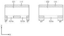
도 2는 세라믹 소체(110)를 구성하는 유전체층(111)과 상기 유전체층에 형성된 내부전극(121, 122)을 나타내는 단면도이다. 본 발명의 일 실시형태에 따르면, 제1 극성의 제1 내부전극(121)과 제2 극성의 제2 내부전극(122)을 한 쌍으로 할 수 있으며, 일 유전체층(111)을 사이에 두고 서로 대향하도록 y-방향으로 배치될 수 있다. 본 발명의 일 실시형태에 따르면, 제1 및 제2 내부전극(121, 122)은 적층 세라믹 커패시터의 실장면 즉, 제1면(1)에 수직으로 배치될 수 있다.
2 is a cross-sectional view showing a
본 발명에서 제1 및 제2 는 서로 다른 극성을 의미할 수 있고, 제1 및 제3은 동일한 극성을 의미할 수 있다.
In the present invention, the first and second may mean different polarities, and the first and third may mean the same polarity.
본 발명의 일 실시형태에 따르면, 제1 및 제2 내부전극은 도전성 금속을 포함하는 도전성 페이스트에 의하여 형성될 수 있다. 상기 도전성 금속은 이에 제한되는 것은 아니나, Ni, Cu, Pd, 또는 이들의 합금일 수 있다.According to an embodiment of the present invention, the first and second internal electrodes may be formed by a conductive paste containing a conductive metal. The conductive metal may be, but is not limited to, Ni, Cu, Pd, or an alloy thereof.
유전체층을 형성하는 세라믹 그린시트 상에 스크린 인쇄법 또는 그라비아 인쇄법과 같은 인쇄법을 통하여 도전성 페이스트로 내부전극층을 인쇄할 수 있다. 내부전극층이 인쇄된 세라믹 그린시트를 번갈아가며 적층하고 소성하여 세라믹 소체를 형성할 수 있다.
The internal electrode layer can be printed with a conductive paste through a printing method such as a screen printing method or a gravure printing method on a ceramic green sheet forming a dielectric layer. The ceramic green sheet on which the internal electrode layers are printed may alternately be laminated and fired to form the ceramic body.
도 2 및 도 3을 참조하면, 제1 및 제2 내부전극(121, 122)은 서로 다른 극성의 외부전극과 연결되기 위하여 각각 인출부(121a, 121b, 122a)를 가지며, 상기 인출부(121a, 121b, 122a)는 세라믹 소체의 제1면(1)으로 노출될 수 있다. 본 발명의 일 실시형태에 따르면 적층 세라믹 커패시터는 수직 적층형으로써, 제1 내부전극의 인출부 및 제2 내부전극의 인출부는 세라믹 소체의 동일면으로 노출될 수 있다.2 and 3, the first and second
본 발명의 일 실시형태에 따르면, 내부전극의 인출부는 내부전극을 형성하는 도체 패턴 중에서 폭(W)이 증가하여 세라믹 소체의 일면으로 노출된 영역을 의미할 수 있다.
According to one embodiment of the present invention, the lead-out portion of the internal electrode may mean a region where the width W of the conductor pattern forming the internal electrode is increased and exposed to one surface of the ceramic body.
본 발명의 일 실시형태에 따르면, 제1 내부전극은 2개의 인출부(121a, 121b)를 가질 수 있다. 상기 제1 내부전극의 2개의 인출부(121a, 121b)는 소정의 간격을 두고 형성되며, 세라믹 소체의 제1면으로 노출될 수 있다.According to an embodiment of the present invention, the first internal electrode may have two
본 발명의 일 실시형태에 따르면, 제1 내부전극의 제1 인출부(121a)는 세라믹 소체의 제3면으로부터 소정의 간격(g1)을 두고 제1면으로 노출될 수 있고, 제1 내부전극의 제2 인출부(121b)는 세라믹 소체의 제4면으로부터 소정의 간격(g1)을 두고 제1면으로 노출될 수 있다.
According to one embodiment of the present invention, the
본 발명의 일 실시형태에 따르면, 제2 내부전극은 1개의 인출부(122a)를 가질 수 있다. 상기 제2 내부전극의 제1 인출부(122a)는 세라믹 소체의 제3면 및 제4면과 소정의 간격(g2)을 두고 형성되며, 세라믹 소체의 제1면으로 노출될 수 있다.
According to one embodiment of the present invention, the second internal electrode may have one
상기 제1 내부전극의 2개의 인출부(121a, 121b)는 각각 제2 내부전극의 인출부(122a)와 서로 중첩되는 영역을 가질 수 있다. 본 발명의 일 실시형태에 따르면, 제1 내부전극의 2개의 인출부(121a, 121b)와 제2 내부전극의 인출부(122a)는 세라믹 소체의 제1면으로 노출된 영역 중 일부 중첩되는 영역을 가질 수 있다. 이에 대한 보다 구체적인 사항은 후술하도록 한다.
The two
본 발명의 일 실시형태에 따르면, 제1 및 제2 내부전극의 단부는 세라믹 소체의 제3면 및 제4면으로 노출될 수 있다. 상기 세라믹 소체의 제3면 및 제4면에는 절연층이 형성되어 내부전극 간의 단락을 방지할 수 있다.
According to one embodiment of the present invention, the ends of the first and second internal electrodes may be exposed to the third and fourth surfaces of the ceramic body. An insulating layer is formed on the third and fourth surfaces of the ceramic body so as to prevent a short circuit between the internal electrodes.
본 발명의 일 실시형태에 따르면, 제1 및 제2 내부전극은 세라믹 소체의 제2면에만 마진부를 형성하고, 제3면 및 제4면에는 마진부 없이 형성될 수 있다. 또한, 제3면, 제4면 및 제1면에는 최소한의 갭(g1, g2)만을 형성하고, 내부전극이 형성될 수 있다. 또한, 제1면에 대해서도 제1 내부전극의 인출부 및 제2 내부전극의 인출부가 일부 중첩될 수 있어 최대한 넓은 면적으로 내부전극이 형성될 수 있다. 이에 따라, 제1 및 제2 내부전극의 중첩 영역이 넓어져 고용량의 적층 세라믹 커패시터를 형성할 수 있다.
According to an embodiment of the present invention, the first and second internal electrodes may form a margin only on the second surface of the ceramic body, and the third surface and the fourth surface may be formed without a margin. Further, only the minimum gaps g1 and g2 may be formed on the third, fourth, and first surfaces, and the internal electrodes may be formed. Also, the lead-out portion of the first internal electrode and the lead-out portion of the second internal electrode can be partially overlapped with respect to the first surface, so that the internal electrode can be formed with the widest area. As a result, the overlap region of the first and second internal electrodes is widened, and a high-capacity multilayer ceramic capacitor can be formed.
일반적으로, 제1 및 제2 내부전극은 중첩되는 영역에 의하여 정전용량을 형성하며, 서로 다른 극성의 외부전극과 연결되는 인출부는 중첩되는 영역을 갖지 않는다. 그러나, 본 발명의 일 실시형태에 따르면, 제1 내부전극의 인출부 및 제2 내부전극의 인출부는 서로 중첩되는 영역을 가질 수 있다.
Generally, the first and second internal electrodes form an electrostatic capacitance by overlapping regions, and the lead portions connected to the external electrodes having different polarities do not have overlapping regions. However, according to one embodiment of the present invention, the lead portion of the first internal electrode and the lead portion of the second internal electrode may have regions overlapping with each other.
도 3은 도 1의 도시된 적층 세라믹 커패시터의 제조공정 중 일부 공정을 나타내는 개략적인 상부 평면면도이다.3 is a schematic top plan view showing some of the manufacturing process of the multilayer ceramic capacitor shown in Fig.
도 3을 참조하면, 제1 및 제2 내부전극을 형성하기 위하여 세라믹 그린시트(111A) 상에 내부전극 패턴(121A, 122A)이 형성되어 있다. 상기 세라믹 그린 시트는 소성에 의하여 도 2에 도시된 유전체층(111)을 형성할 수 있다.Referring to FIG. 3,
내부전극 패턴이 형성된 세라믹 그린 시트를 적층하고, 절단하여 개별 칩 단위의 세라믹 소체를 제조할 수 있다. 공정의 편의를 위하여 하나의 내부전극 패턴이 형성되고, 상기 내부전극 패턴의 절단 공정에 의하여 도 2에 도시된 바와 같은 제1 및 제2 내부전극이 복수개 형성될 수 있다. 도 3은 2점 쇄선으로 절단선을 도시하였으며, 절단선에 따라 절단하는 경우 내부전극 패턴 중 일부(121A)는 제1 내부전극이 되고, 내부전극 패턴 중 일부(122A)는 제2 내부전극이 될 수 있다. 도 3을 참조하면, 제1 내부전극 패턴(121A)과 제2 내부전극 패턴(122A)은 인출부를 갖도록 형성될 수 있으며, 인출부 사이에는 갭(g1, g2)이 형성될 수 있다. 제1 및 제2 내부전극 패턴의 절단선은 상기 갭(g1, g2) 상에서 형성될 수 있다.A ceramic green sheet on which an internal electrode pattern is formed can be laminated and cut to produce a ceramic body of an individual chip unit. One internal electrode pattern is formed for convenience of the process, and a plurality of first and second internal electrodes as shown in FIG. 2 may be formed by the step of cutting the internal electrode pattern. 3 shows a cut line taken along the two-dot chain line. In the case of cutting along the cut line, a
만약 절단선이 제1 및 제2 내부전극 패턴의 인출부 상에 형성되는 경우 설계된 대로 제1 및 제2 내부전극의 인출부가 서로 중첩영역을 형성할 수 없게 된다. 제1 및 제2 내부전극의 인출부가 단락되거나, 세라믹 소체의 노출면에 있어서 서로 다른 극성의 외부전극과 연결될 수 있도록 일부만 중첩되도록 형성되지 않을 수 있다.If cut lines are formed on the lead portions of the first and second internal electrode patterns, the lead portions of the first and second internal electrodes can not form overlapping regions with each other as designed. The lead portions of the first and second internal electrodes may not be formed so as to partially overlap so as to be short-circuited or connected to external electrodes of different polarities on the exposed surface of the ceramic body.
그러나, 본 발명의 일 실시형태에 따르면, 인출부 사이에 갭(g1, g2)이 형성되어 있어 제1 및 제2 내부전극 패턴의 절단선은 오차 범위가 줄어들 수 있다. 즉, 상기 갭(g1, g2) 상 절단선이 형성되면 제1 및 제2 내부전극이 단락되거나 설계 범위를 벗어나지 않아, 절단 정밀도가 향상될 수 있다.
However, according to one embodiment of the present invention, since the gaps g1 and g2 are formed between the lead portions, the error range of the cut lines of the first and second internal electrode patterns can be reduced. That is, when the cutting lines are formed on the gaps g1 and g2, the first and second internal electrodes are short-circuited or the design range is not exceeded, so that the cutting accuracy can be improved.
도 4를 참조하면, 세라믹 소체의 일면에는 내부전극과 연결되도록 외부전극이 형성될 수 있다. 보다 구체적으로, 세라믹 소체의 제1면으로 노출된 제1 내부전극의 제1 인출부(121a)와 연결되도록 제1 외부전극(131)이 형성될 수 있고, 세라믹 소체의 제1면으로 노출된 제1 내부전극의 제2 인출부(121b)와 연결되도록 제3 외부전극(133)이 형성될 수 있다. 또한, 세라믹 소체의 제1면으로 인출된 제2 내부전극의 제1 인출부(122a)와 연결되도록 제2 외부전극(132)이 형성될 수 있다.
Referring to FIG. 4, an external electrode may be formed on one surface of the ceramic body so as to be connected to the internal electrode. More specifically, the first
상기 제1 외부전극(131)은 제1 내부전극의 제1 인출부(121a) 중 제2 내부전극의 제1 인출부(122a)와 중첩되지 않은 영역과 연결될 수 있고, 제3 외부전극(133)은 제1 내부전극의 제2 인출부(121b) 중 제2 내부전극의 제1 인출부(122a)와 중첩되지 않은 영역과 연결될 수 있다. 또한, 제2 외부전극(132)은 제2 내부전극의 제1 인출부(122a) 중 제1 내부전극의 제1 인출부 및 제2 인출부(121a, 121b)와 중첩되지 않은 영역과 연결될 수 있다.The first
도 4의 오른쪽 도면은 제1 내부전극의 제1 및 제2 인출부(121a, 121b)와 제2 내부전극의 인출부(122a)의 중첩된 영역이 화살표로 표시되어 있으며, 제2 내부전극(122)과 중첩된 제1 내부전극은 점선으로 표시되어 있다.4, the overlapping regions of the first and second lead-out
본 발명의 일 실시형태에 따르면, 제1 내부전극의 인출부와 제2 내부전극의 인출부는 서로 중첩되는 영역을 가지되, 서로 다른 극성을 나타내는 외부전극과 연결될 수 있다.
According to an embodiment of the present invention, the lead portion of the first internal electrode and the lead portion of the second internal electrode may be connected to external electrodes having regions overlapping each other and exhibiting different polarities.
본 발명의 일 실시형태에 따르면, 세라믹 소체의 일면에는 절연층(141, 142, 143, 144)이 형성될 수 있다. 보다 구체적으로 세라믹 소체의 제1면에는 제1 절연층(141) 및 제2 절연층(142)이 형성될 수 있고, 세라믹 소체의 제3면 및 제4면에는 각각 제3 절연층(143) 및 제4 절연층(144)이 형성될 수 있다.According to an embodiment of the present invention, insulating
세라믹 소체의 제1면에 형성된 제1 절연층(141)은 제1 및 제2 외부전극(131, 132) 사이에 형성될 수 있고, 제2 절연층(142)은 제2 및 제3 외부전극(132, 133) 사이에 형성될 수 있다. 상기 제1 및 제2 절연층(141, 142)은 제1면으로 노출된 제1 내부전극의 인출부(121a, 121b)와 제2 내부전극의 인출부(122a)를 덮도록 형성될 수 있다. 제1 및 제2 절연층(141, 142)은 제1 및 제2 인출부의 중첩되는 영역을 모두 덮고, 제1 내부전극의 인출부 및 제2 내부전극의 인출부의 노출된 영역까지 덮도록 형성될 수 있다.
The first insulating
본 발명의 일 실시형태에 따르면, 도 3에 도시된 바와 같이 상기 제1 및 제2 절연층(141, 142)은 제1 및 제2 외부전극 사이의 세라믹 소체의 제1면을 완전히 메우도록 형성될 수 있다.3, the first and second insulating
또한 도시되지 않았으나, 본 발명의 일 실시형태에 따르면, 제1 및 절연층(141, 142)은 제1 내부전극의 인출부(121a, 121b)와 제2 내부전극의 인출부(122a)의 중첩 영역만을 덮도록 형성되고, 제1 내지 제3 외부전극(131, 132, 133)과 소정의 간격을 두고 형성될 수 있다.
Although not shown, according to an embodiment of the present invention, the first and the insulating
본 발명의 일 실시형태에 따르면, 제1 및 제2 내부전극(121, 122)의 단부가 노출된 세라믹 소체의 제3면 및 제4면에는 각각 제3 절연층(143) 및 제4 절연층(144)이 형성될 수 있다.According to an embodiment of the present invention, a third
상기 제3 절연층(143)은 세라믹 소체의 제2면에 형성된 마진부 유전체층과 연결될 수 있다. 또한, 도 2에 도시된 바와 같이 제1 내부전극의 제1 인출부(121a)는 세라믹 소체의 제3면과 소정의 간격(g1)을 두고 형성되어, 세라믹 소체의 제3면에는 유전체층이 노출되어 있다. 상기 제3 절연층(143)은 세라믹 소체의 제3면으로 노출된 유전체층과 연결될 수 있다.The third
상기 제4 절연층(144)은 세라믹 소체의 제2면에 형성된 마진부 유전체층과 연결될 수 있다. 또한, 도 2에 도시된 바와 같이 제1 내부전극의 제2 인출부(121b)는 세라믹 소체의 제4면과 소정의 간격(g1)을 두고 형성되어, 세라믹 소체의 제4면에는 유전체층이 노출되어 있다. 상기 제4 절연층(144)은 세라믹 소체의 제4면으로 노출된 유전체층과 연결될 수 있다.The fourth insulating
본 발명의 일 실시형태에 따르면 절연층은 유전체층과 동일하거나 유사한 물질로 형성될 수 있으며, 유전체층과 연결되는 경우 절연층과 세라믹 소체의 결합 강도가 향상될 수 있다.
According to an embodiment of the present invention, the insulating layer may be formed of the same or similar material as the dielectric layer, and the coupling strength between the insulating layer and the ceramic body may be improved when the dielectric layer is connected to the dielectric layer.
본 발명의 일 실시형태에 따르면, 절연층(141, 142, 143, 144)은 세라믹 슬러리로 형성될 수 있다. 상기 세라믹 슬러리의 양 및 형상을 조절하여 절연층의 형성 위치 및 높이를 조절할 수 있다. 상기 절연층(141, 142, 143, 144)은 소성 공정에 의하여 세라믹 소체가 형성된 후, 상기 세라믹 소체에 세라믹 슬러리를 도포하고, 소성하여 형성될 수 있다.According to one embodiment of the present invention, the insulating
또는 세라믹 소체를 형성하는 세라믹 그린시트 상에 절연층을 형성하는 세라믹 슬러리를 형성하고, 세라믹 그린시트와 함께 소성되어 형성될 수 있다.Or may be formed by firing together with a ceramic green sheet to form a ceramic slurry for forming an insulating layer on the ceramic green sheet forming the ceramic body.
상기 세라믹 슬러리의 형성 방법은 특별히 제한되지 않으며, 예를 들면 스프레이 방식으로 분사하거나, 롤러를 이용한 도포, 코팅, 부착 등의 방법을 이용할 수 있다.
The method of forming the ceramic slurry is not particularly limited, and for example, a spray method, a coating method using a roller, a coating method, and the like can be used.
본 발명의 일 실시형태에 따르면, 절연층(141, 142, 143, 144)은 세라믹 소체의 일면으로 노출된 제1 및 제2 내부전극의 인출부(121a, 121b, 122a), 제1 및 제2 내부전극(121, 122)의 단부를 덮어 내부전극 간의 단락을 방지하고, 내습 특성 저하 등의 내부결함을 방지할 수 있다.
According to one embodiment of the present invention, the insulating
본 발명의 일 실시형태에 따르면, 제1 및 제2 내부전극은 인출부에도 중첩 영역이 형성되어 적층 세라믹 커패시터의 용량이 증가될 수 있다. 또한, 외부 극성이 인가되는 제1 및 제2 내부전극 간의 거리가 가까워져 커런트 루프(current loop)가 짧아질 수 있고, 이에 따라 등가직렬인덕턴스(ESL, Equivalent Series Inductance)가 낮아질 수 있다.
According to an embodiment of the present invention, the first and second internal electrodes may also have overlapping regions in the lead-out portions so that the capacity of the multilayer ceramic capacitor can be increased. In addition, the distance between the first and second internal electrodes to which the external polarity is applied is shortened, so that the current loop can be shortened, and the equivalent series inductance (ESL) can be lowered.
도 5는 본 발명의 다른 실시형태에 따른 적층 세라믹 커패시터를 나타내는 단면도이다. 상술한 실시예와 다른 구성요소를 중심으로 설명하며, 동일한 구성요소에 대한 자세한 설명은 생략한다.5 is a cross-sectional view showing a multilayer ceramic capacitor according to another embodiment of the present invention. The description will be focused on components different from those of the above-described embodiment, and detailed description of the same components will be omitted.
도 5를 참조하면, 도 4와 유사하게 세라믹 소체의 제1면에는 제1 내지 제3 외부전극(131, 132, 133)이 형성될 수 있다. 또한, 세라믹 소체의 제1면에는 제1 및 제2 절연층(141, 142)이 형성되고, 제3면에는 제3 절연층(143)이 형성되며, 제4면에는 제4 절연층(144)이 형성될 수 있다.Referring to FIG. 5, similarly to FIG. 4, first to third
본 발명의 일 실시형태에 따르면, 제1 절연층(141)은 제1 및 제2 외부전극 (131, 132)사이에 형성되고, 제2 절연층(142)은 제2 및 제3 외부전극(132, 133) 사이에 형성될 수 있다.The first insulating
본 발명의 일 실시형태에 따르면, 제1 및 제2 절연층(141, 142)의 높이(h2)는 제1 내지 제3 외부전극(131, 132, 133)의 높이(h1)보다 작게 형성될 수 있다. 상기 절연층 및 외부전극의 높이는 제1면을 기준으로 측정될 수 있다.The height h2 of the first and second insulating
본 발명의 일 실시형태에 따르면, 상기 제1 및 제2 절연층(141, 142)의 높이가 제1 내지 제2 외부전극의 높이보다 낮아 적층 세라믹 커패시터가 회로 기판 상에 보다 안정적으로 실장될 수 있다.According to an embodiment of the present invention, since the height of the first and second insulating
또한, 도시되지 않았으나, 제1 및 제2 절연층의 높이는 서로 다르게 형성될 수 있다.
Although not shown, the heights of the first and second insulating layers may be different from each other.
본 발명의 일 실시형태에 따르면, 제3 절연층 또는 제4 절연층(143, 144)의 두께(D2)는 제1 외부전극(131) 또는 제3 외부전극(133)의 두께(D1)보다 크게 형성될 수 있다. 상기 절연층 및 외부전극의 두께는 제3면 또는 제4면을 기준으로 측정될 수 있다.The thickness D2 of the third or fourth insulating
또한, 도시되지 않았으나, 본 발명의 일 실시형태에 따르면 제3 절연층 또는 제4 절연층의 두께는 외부전극의 두께보다 작게 형성될 수 있다.
Also, though not shown, according to an embodiment of the present invention, the thickness of the third insulating layer or the fourth insulating layer may be smaller than the thickness of the external electrode.
도 6 내지 도 9는 본 발명의 또 다른 실시형태에 따른 적층 세라믹 커패시터를 나타낸다. 도 6은 본 실시형태에 따른 적층 세라믹 커패시터를 나타내는 개략적인 사시도이고, 도 7은 도 6에 도시된 적층 세라믹 커패시터의 내부전극 구조를 나타내는 단면도이며, 도 8는 도 6에 도시된 적층 세라믹 커패시터의 제조공정 중 일부 공정을 나타내는 개략적인 상부 평면면도이다. 도 9는 도 6에 도시된 적층 세라믹 커패시터의 단면도이다. 상술한 실시예와 다른 구성요소를 중심으로 설명하며, 동일한 구성요소에 대한 자세한 설명은 생략한다.
6 to 9 show multilayer ceramic capacitors according to still another embodiment of the present invention. 6 is a cross-sectional view showing the internal electrode structure of the multilayer ceramic capacitor shown in FIG. 6, and FIG. 8 is a cross-sectional view of the multilayer ceramic capacitor shown in FIG. 6 And is a schematic top plan view showing some processes in the manufacturing process. 9 is a cross-sectional view of the multilayer ceramic capacitor shown in Fig. The description will be focused on components different from those of the above-described embodiment, and detailed description of the same components will be omitted.
도 6 내지 도 9를 참조하면, 본 실시형태에 따른 적층 세라믹 커패시터는 6단자 수직 적층형 커패시터일 수 있다. “6 단자(6-terminal)”는 커패시터의 단자로서 6개의 단자가 회로기판에 접속될 수 있음을 의미한다.
6 to 9, the multilayer ceramic capacitor according to the present embodiment may be a 6-terminal vertical stacked capacitor. &Quot; 6-terminal " means a terminal of a capacitor, and 6 terminals can be connected to a circuit board.
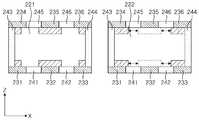
본 실시 형태에 따른 적층 세라믹 커패시터는 세라믹 소체(210); 상기 세라믹 소체의 내부에 형성되는 내부전극(221, 222); 상기 세라믹 소체의 일면에 형성되는 절연층(241, 242, 243, 244, 245, 246) 및 외부전극(231, 232, 233, 234, 235, 236)을 포함할 수 있다.
The multilayer ceramic capacitor according to the present embodiment includes a
도 7은 세라믹 소체(210)를 구성하는 유전체층(211)과 상기 유전체층에 형성된 내부전극(221, 222)을 나타내는 단면도이다. 본 발명의 일 실시형태에 따르면, 제1 극성의 제1 내부전극(221)과 제2 극성의 제2 내부전극(222)을 한 쌍으로 할 수 있으며, 일 유전체층(211)을 사이에 두고 서로 대향하도록 y-방향으로 배치될 수 있다. 본 발명의 일 실시형태에 따르면, 제1 및 제2 내부전극(221, 222)은 적층 세라믹 커패시터의 실장면에 수직으로 배치될 수 있다.7 is a cross-sectional view showing a
본 실시형태에 따르면 적층 세라믹 커패시터의 실장면은 제1면 또는 이에 대향하는 제2면이 될 수 있다.
According to the present embodiment, the mounting surface of the multilayer ceramic capacitor may be the first surface or the second surface facing the first surface.
도 7 및 도 9를 참조하면, 제1 및 제2 내부전극(221, 222)은 서로 다른 극성의 외부전극과 연결되기 위하여 각각 인출부(221a, 221b, 221c, 221d, 222a, 222b)를 가질 수 있다.Referring to FIGS. 7 and 9, the first and second
본 발명의 일 실시형태에 따르면 적층 세라믹 커패시터는 수직 적층형으로써, 제1 내부전극의 인출부 및 제2 내부전극의 인출부는 세라믹 소체의 동일면으로 노출될 수 있다.According to one embodiment of the present invention, the multilayer ceramic capacitor is vertically stacked, and the lead portion of the first internal electrode and the lead portion of the second internal electrode can be exposed to the same side of the ceramic body.
본 발명의 일 실시형태에 따르면, 제1 내부전극은 4개의 인출부(221a, 221b, 221c, 221d)를 가질 수 있다. 본 발명의 일 실시형태에 따르면, 제1 내부전극의 2개의 인출부(221a, 221b)는 서로 소정의 간격을 두고 세라믹 소체의 제1면으로 노출되고, 제1 내부전극의 다른 2개의 인출부(221c, 221d)는 서로 소정의 간격을 두고 세라믹 소체의 제1면에 대향하는 제2면으로 노출될 수 있다.According to an embodiment of the present invention, the first internal electrode may have four
본 발명의 일 실시형태에 따르면, 제1 내부전극의 제1 인출부(221a)는 세라믹 소체의 제3면으로부터 소정의 간격(g1)을 두고 제1면으로 노출될 수 있고, 제1 내부전극의 제2 인출부(221b)는 세라믹 소체의 제4면으로부터 소정의 간격(g1)을 두고 제1면으로 노출될 수 있다. 또한, 유사한 방식으로 제1 내부전극의 제3 인출부(221c)는 세라믹 소체의 제3면으로부터 소정의 간격(g1)을 두고 제2면으로 노출될 수 있고, 제1 내부전극의 제4 인출부(221d)는 세라믹 소체의 제4면으로부터 소정의 간격(g1)을 두고 제2면으로 노출될 수 있다.
According to one embodiment of the present invention, the
본 발명의 일 실시형태에 따르면, 제2 내부전극은 2개의 인출부(221a, 221b)를 가질 수 있다. 본 발명의 일 실시형태에 따르면, 제2 내부전극의 제1 인출부(222a)는 세라믹 소체의 제3면 및 제4면과 소정의 간격(g2)을 두고 형성되며, 세라믹 소체의 제1면으로 노출되고, 제2 내부전극의 제2 인출부(222b)는 세라믹 소체의 제3면 및 제4면과 소정의 간격(g2)을 두고 형성되며, 세라믹 소체의 제1면에 대향하는 제2면으로 노출될 수 있다.
According to one embodiment of the present invention, the second internal electrode may have two
상기 제1 내부전극의 제1 및 제2 인출부(221a, 221b)는 각각 제2 내부전극의 제1 인출부(222a)와 서로 중첩되는 영역을 가질 수 있다. 보다 구체적으로, 제1 내부전극의 제1 및 제2 인출부(221a, 221b)와 제2 내부전극의 제1 인출부(222a)는 세라믹 소체의 제1면으로 노출된 영역 중 일부 중첩되는 영역을 가질 수 있다.The first and
또한, 유사한 방식으로 제1 내부전극의 제3 및 제4 인출부(221c, 221d)는 각각 제2 내부전극의 제2 인출부(222b)와 서로 중첩되는 영역을 가질 수 있다. 보다 구체적으로, 제1 내부전극의 제3 및 제4 인출부(221c, 221d)와 제2 내부전극의 제2 인출부(222b)는 세라믹 소체의 제2면으로 노출된 영역 중 일부 중첩되는 영역을 가질 수 있다. 이에 대한 보다 구체적인 사항은 후술하도록 한다.
In a similar manner, the third and fourth
또한, 본 발명의 일 실시형태에 따르면, 제1 및 제2 내부전극(221, 222)의 단부는 세라믹 소체의 제3면 및 제4면으로 노출될 수 있다. 상기 세라믹 소체의 제3면 및 제4면에는 절연층이 형성되어 제1 및 제2 내부전극 간의 단락을 방지할 수 있다.
Also, according to one embodiment of the present invention, the ends of the first and second
본 발명의 일 실시형태에 따르면, 제1 및 제2 내부전극은 세라믹 소체의 유전체층에 최소한의 갭(g1, g2)만을 형성하고, 내부전극이 형성될 수 있다. 또한, 제1 내부전극의 인출부 및 제2 내부전극의 인출부는 일부 영역이 중첩되도록 형성되어 유전체층에 최대한 넓은 면적으로 내부전극이 형성될 수 있다. 이에 따라, 제1 및 제2 내부전극의 중첩 영역이 넓어져 고용량의 적층 세라믹 커패시터를 형성할 수 있다.
According to one embodiment of the present invention, the first and second internal electrodes form only the minimum gaps g1 and g2 in the dielectric layer of the ceramic body, and the internal electrodes can be formed. The outgoing portion of the first internal electrode and the outgoing portion of the second internal electrode may be formed so as to overlap a part of the region, so that the internal electrode may be formed in the dielectric layer as much as possible. As a result, the overlap region of the first and second internal electrodes is widened, and a high-capacity multilayer ceramic capacitor can be formed.
도 8은 도 6의 도시된 적층 세라믹 커패시터의 제조공정 중 일부 공정을 나타내는 개략적인 상부 평면면도이다.8 is a schematic top plan view showing some of the manufacturing process of the multilayer ceramic capacitor shown in Fig.
도 8을 참조하면, 제1 및 제2 내부전극을 형성하기 위하여 세라믹 그린시트(211A) 상에 내부전극 패턴(221A, 222A)이 형성되어 있다. 상기 세라믹 그린 시트는 소성에 의하여 도 7에 도시된 유전체층(211)을 형성할 수 있다.Referring to FIG. 8,
도 8은 2점 쇄선으로 절단선을 도시하였으며, 절단선에 따라 절단하는 경우 내부전극 패턴 중 일부(221A)는 제1 내부전극이 되고, 내부전극 패턴 중 일부(222A)는 제2 내부전극이 될 수 있다.8 shows a cut line taken along the two-dot chain line. In the case of cutting along the cut line,
도 8을 참조하면, 제1 내부전극 패턴(221A)과 제2 내부전극 패턴(222A)은 인출부를 갖도록 형성될 수 있으며, 인출부 사이에는 갭(g1, g2)이 형성될 수 있다. 제1 및 제2 내부전극 패턴의 절단선은 상기 갭(g1, g2) 상에서 형성될 수 있다.Referring to FIG. 8, the first
상술한 바와 같이 본 발명의 일 실시형태에 따르면, 인출부 사이에 갭(g1, g2)이 형성되어 있어 제1 및 제2 내부전극 패턴의 절단선은 오차 범위가 줄어들 수 있다. 즉, 상기 갭(g1, g2) 상 절단선이 형성되면 제1 및 제2 내부전극이 단락되거나 설계 범위를 벗어나지 않아, 절단 정밀도가 향상될 수 있다.
As described above, according to the embodiment of the present invention, since the gaps g1 and g2 are formed between the lead portions, the error range of the cut lines of the first and second internal electrode patterns can be reduced. That is, when the cutting lines are formed on the gaps g1 and g2, the first and second internal electrodes are short-circuited or the design range is not exceeded, so that the cutting accuracy can be improved.
도 9를 참조하면, 세라믹 소체의 일면에는 내부전극과 연결되도록 외부전극이 형성될 수 있다. 보다 구체적으로, 세라믹 소체의 제1면으로 노출된 제1 내부전극의 제1 및 제2 인출부(221a, 221b)와 각각 연결되도록 제1 및 제3 외부전극(231, 233)이 형성될 수 있고, 세라믹 소체의 제1면으로 노출된 제2 내부전극의 제1 인출부(222a)와 연결되도록 제2 외부전극(232)이 형성될 수 있다.Referring to FIG. 9, external electrodes may be formed on one surface of the ceramic body to be connected to internal electrodes. More specifically, the first and third
또한, 이와 유사하게, 세라믹 소체의 제2면으로 노출된 제1 내부전극의 제3 및 제4 인출부(221c, 221d)와 각각 연결되도록 제4 및 제6 외부전극(234, 236)이 형성될 수 있고, 세라믹 소체의 제2면으로 노출된 제2 내부전극의 제2 인출부(222b)와 연결되도록 제5 외부전극(235)이 형성될 수 있다.
Likewise, the fourth and sixth
본 발명에서 제1 및 제2 는 서로 다른 극성을 의미할 수 있고, 제1, 제3, 제4, 제6은 동일한 극성을 의미할 수 있고, 제2 및 제5는 동일한 극성을 의미할 수 있다.
In the present invention, the first and second may mean different polarities, and the first, third, fourth, and sixth may mean the same polarity, and the second and fifth may mean the same polarity have.
상술한 실시예와 유사하게, 상기 제1, 제3, 제4 및 제6 외부전극(231, 233, 234, 236)은 제1 내부전극의 제1 내지 제4 인출부(221a, 221b, 221c, 221d) 중 제2 내부전극의 제1 및 제2 인출부(222a, 222b)와 중첩되지 않은 영역과 연결될 수 있다.The first, third, fourth and sixth
도 9의 오른쪽 도면은 제1 내부전극의 제1 내지 제4 인출부(221a, 221b, 221c, 221d)와 제2 내부전극의 제1 및 제2 인출부(222a, 222b)의 중첩된 영역이 화살표로 표시되어 있으며, 제2 내부전극(222)과 중첩된 제1 내부전극은 점선으로 표시되어 있다.
9, the overlapped region of the first to
본 발명의 일 실시형태에 따르면, 제1 내부전극의 인출부와 제2 내부전극의 인출부는 서로 동일면으로 노출되고, 서로 중첩되는 영역을 가지되, 서로 다른 극성을 나타내는 외부전극과 연결될 수 있다.
According to an embodiment of the present invention, the lead portion of the first internal electrode and the lead portion of the second internal electrode may be connected to an external electrode which is exposed in the same plane and overlaps with each other and exhibits different polarities.
본 발명의 일 실시형태에 따르면, 세라믹 소체의 일면에는 절연층(241, 242, 243, 244, 245, 246)이 형성될 수 있다. 보다 구체적으로 세라믹 소체의 제1면에는 제1 절연층(241) 및 제2 절연층(242)이 형성될 수 있고, 세라믹 소체의 제3면 및 제4면에는 각각 제3 절연층(243) 및 제4 절연층(244)이 형성될 수 있으며, 세라믹 소체의 제2면에는 제5 절연층(245) 및 제6 절연층(246)이 형성될 수 있다.
According to an embodiment of the present invention, insulating
세라믹 소체의 제1면에 형성된 제1 절연층(241)은 제1 및 제2 외부전극(231, 232) 사이에 형성될 수 있고, 제2 절연층(242)은 제2 및 제3 외부전극(232, 233) 사이에 형성될 수 있다. 상기 제1 및 제2 절연층(241, 242)은 제1면으로 노출된 제1 내부전극의 인출부(221a, 221b)와 제2 내부전극의 인출부(222a)를 덮도록 형성될 수 있다. 제1 및 제2 절연층(241, 242)은 제1 및 제2 인출부의 중첩되는 영역을 모두 덮고, 제1 내부전극의 인출부 및 제2 내부전극의 인출부의 노출된 영역까지 덮도록 형성될 수 있다.The first insulating
또한, 본 발명의 일 실시형태에 따르면, 도 9에 도시된 바와 같이 상기 제1 및 제2 절연층(241, 242)은 제1 및 제2 외부전극 사이의 세라믹 소체의 제1면을 완전히 메우도록 형성될 수 있다.9, the first and second insulating
또한 도시되지 않았으나, 본 발명의 일 실시형태에 따르면, 제1 및 절연층(241, 242)은 제1 내부전극의 인출부(221a, 221b)와 제2 내부전극의 인출부(222a)의 중첩 영역만을 덮도록 형성되고, 제1 내지 제3 외부전극(231, 232, 233)과 소정의 간격을 두고 형성될 수 있다.
Although not shown, according to an embodiment of the present invention, the first and the insulating
또한, 상기와 유사한 방식으로 세라믹 소체의 제2면에는 제5 절연층(245) 및 제6 절연층(246)이 형성될 수 있다. 상기 제5 절연층(244)은 제4 및 제5 외부전극(234, 235) 사이에 형성될 수 있고, 제6 절연층(246)은 제5 및 제6 외부전극(235, 236) 사이에 형성될 수 있다. 상기 제5 및 제6 절연층의 형성 패턴은 상술한 제1 및 제2 절연층의 형성패턴과 같이 다양하게 변경될 수 있다.
In addition, a fifth insulating
본 발명의 일 실시형태에 따르면, 제1 및 제2 내부전극(221, 222)의 단부가 노출된 세라믹 소체의 제3면 및 제4면에는 각각 제3 절연층(243) 및 제4 절연층(244)이 형성될 수 있다.According to an embodiment of the present invention, a third
도 9 및 도 10에 도시된 바와 같이 제1 내부전극의 제1 및 제3 인출부(221a, 221c)와 제2 내부전극의 제1 및 제2 인출부(222a, 222b)는 세라믹 소체의 제3면과 소정의 간격(g1, g2)을 두고 형성되어 세라믹 소체의 제3면에는 유전체층이 노출되어 있다. 상기 제3 절연층(243)은 세라믹 소체의 제3면으로 노출된 유전체층과 연결될 수 있다.As shown in FIGS. 9 and 10, the first and
또한, 제1 내부전극의 제2 및 제4 인출부(221c, 221d)와 제2 내부전극의 제1 및 제2 인출부(222a, 222b)는 세라믹 소체의 제4면과 소정의 간격(g1, g2)을 두고 형성되어 세라믹 소체의 제4면에는 유전체층이 노출되어 있다. 상기 제4 절연층(244)은 세라믹 소체의 제4면으로 노출된 유전체층과 연결될 수 있다.
The second and fourth
본 발명의 일 실시형태에 따르면 절연층은 유전체층과 동일하거나 유사한 물질로 형성될 수 있으며, 유전체층과 연결되는 경우 절연층과 세라믹 소체의 결합 강도가 향상될 수 있다.
According to an embodiment of the present invention, the insulating layer may be formed of the same or similar material as the dielectric layer, and the coupling strength between the insulating layer and the ceramic body may be improved when the dielectric layer is connected to the dielectric layer.
또한, 상기 절연층은 세라믹 소체의 일면으로 노출된 제1 및 제2 내부전극의 단부, 제1 및 제2 내부전극의 인출부를 덮어 내부전극 간의 단락을 방지하고, 내습 특성 저하 등의 내부결함을 방지할 수 있다.
The insulating layer covers the end portions of the first and second internal electrodes exposed at one surface of the ceramic body and the lead portions of the first and second internal electrodes to prevent a short circuit between the internal electrodes and to prevent internal defects .
본 실시형태에 따르면, 제1 및 제2 내부전극은 인출부에도 중첩 영역이 형성되어 적층 세라믹 커패시터의 용량이 증가될 수 있다. 또한, 외부 극성이 인가되는 제1 및 제2 내부전극 간의 거리가 가까워져 커런트 루프(current loop)가 짧아질 수 있고, 이에 따라 등가직렬인덕턴스(ESL, Equivalent Series Inductance)가 낮아질 수 있다.
According to the present embodiment, the first and second internal electrodes are also formed in the lead-out area so that the capacity of the multilayer ceramic capacitor can be increased. In addition, the distance between the first and second internal electrodes to which the external polarity is applied is shortened, so that the current loop can be shortened, and the equivalent series inductance (ESL) can be lowered.
또한 도시되지 않았으나, 제1 내부전극 또는 제2 내부전극은 2 개 이상의 인출부를 가질 수 있으며, 서로 다른 극성의 인출부가 서로 중첩되도록 형성될 수 있다. 또한, 제1 내부전극 또는 제2 내부전극에 형성된 인출부는 세라믹 소체의 동일면으로 노출되거나 세라믹 소체의 서로 다른 면으로 노출될 수 있다. 당업자에 의하여 내부전극이 가지는 인출부의 갯수, 인출부의 위치 등은 다양하게 변경될 수 있다.
Although not shown, the first internal electrode or the second internal electrode may have two or more lead portions, and the lead portions of different polarities may be formed to overlap with each other. The lead portions formed on the first internal electrode or the second internal electrode may be exposed on the same side of the ceramic body or on different sides of the ceramic body. The number of lead portions of the internal electrode, the position of the lead portion, and the like may be variously changed by those skilled in the art.
본 발명은 상술한 실시 형태 및 첨부된 도면에 의해 한정되는 것이 아니며, 첨부된 청구범위에 의해 한정하고자 한다. 따라서, 청구범위에 기재된 본 발명의 기술적 사상을 벗어나지 않는 범위 내에서 당 기술분야의 통상의 지식을 가진 자에 의해 다양한 형태의 치환, 변형 및 변경이 가능할 것이며, 이 또한 본 발명의 범위에 속한다고 할 것이다.The present invention is not limited by the above-described embodiments and the accompanying drawings, but is intended to be limited only by the appended claims. It will be apparent to those skilled in the art that various changes in form and details may be made therein without departing from the spirit and scope of the invention as defined by the appended claims. something to do.
110: 세라믹 소체 111: 유전체층
121, 122: 제1 및 제2 내부전극 131, 132: 제1 및 제2 외부전극
140: 절연층110: ceramic body 111: dielectric layer
121, 122: first and second
140: insulating layer
Claims (13)
Translated fromKorean상기 세라믹 소체의 내부에 형성되며, 상기 세라믹 소체의 제1면, 제3면 및 제4면으로 노출되고, 상기 제1면으로 노출된 영역 중 일부가 서로 중첩되는 인출부를 가지는 제1 및 제2 내부전극;
상기 세라믹 소체의 제1면에 형성되며, 상기 인출부와 각각 연결되는 외부전극; 및
상기 세라믹 소체의 제1면, 상기 제1면과 연결된 제3면 및 제4면에 형성되는 절연층;을 포함하고,
상기 인출부는 세라믹 소체의 제3면 또는 제4면과 소정의 간격을 두고 형성되며, 상기 제1 내부전극은 서로 소정의 간격을 두고 상기 세라믹 소체의 제1 면으로 노출되는 제1 및 제2 인출부를 가지고, 상기 제2 내부전극은 상기 세라믹 소체의 제3면 및 제4면과 소정의 간격을 두고 형성되는 제1 인출부를 가지며, 상기 세라믹 소체의 제1면에 형성된 외부전극은 상기 제1 내부전극의 제1 및 제2 인출부 및 상기 제2 내부전극의 제1 인출부와 각각 연결되는 제1 내지 제3 외부전극을 포함하는 적층 세라믹 커패시터.
Ceramic body;
The first and second surfaces of the ceramic body being exposed to the first surface, the third surface and the fourth surface of the ceramic body and having a lead portion in which a part of the regions exposed on the first surface overlap with each other; Internal electrodes;
An outer electrode formed on a first surface of the ceramic body and connected to the lead portion; And
And an insulating layer formed on the first surface of the ceramic body, the third surface connected to the first surface, and the fourth surface,
Wherein the lead portion is formed at a predetermined distance from a third surface or a fourth surface of the ceramic body, and the first internal electrode is divided into first and second lead-out portions exposed at a first surface of the ceramic body, Wherein the second internal electrode has a first lead portion formed at a predetermined interval from a third surface and a fourth surface of the ceramic body, and an external electrode formed on the first surface of the ceramic body is connected to the first internal And first to third external electrodes connected to the first and second lead portions of the electrode and the first lead portions of the second internal electrode, respectively.
상기 제1 인출부는 상기 세라믹 소체의 제3면과 소정의 간격을 두고 형성되고, 상기 제2 인출부는 상기 세라믹 소체의 제4면과 소정의 간격을 두고 형성되는 적층 세라믹 커패시터.
The method according to claim 1,
Wherein the first lead portion is formed at a predetermined distance from the third surface of the ceramic body and the second lead portion is formed at a predetermined distance from the fourth surface of the ceramic body.
상기 제1 및 제2 내부전극은 세라믹 소체의 실장면에 대하여 수직으로 배치되는 적층 세라믹 커패시터.
The method according to claim 1,
Wherein the first and second internal electrodes are disposed perpendicular to a mounting surface of the ceramic body.
상기 절연층은 세라믹 슬러리로 형성되는 적층 세라믹 커패시터.
The method according to claim 1,
Wherein the insulating layer is formed of a ceramic slurry.
상기 외부전극은 상기 제1 및 제2 내부전극의 인출부 중 서로 중첩되지 않는 영역과 연결되는 적층 세라믹 커패시터.
The method according to claim 1,
Wherein the external electrodes are connected to regions of the lead portions of the first and second internal electrodes that do not overlap each other.
상기 세라믹 소체의 제1면에 형성되는 절연층은 제1 및 제2 내부전극의 인출부 중 서로 중첩되는 영역을 모두 덮도록 형성되는 적층 세라믹 커패시터.
The method according to claim 1,
Wherein the insulating layer formed on the first surface of the ceramic body is formed so as to cover all of the overlapping portions of the lead portions of the first and second internal electrodes.
상기 세라믹 소체의 제1면에 형성되는 절연층은 상기 세라믹 소체의 제1면으로부터 측정되는 제1 및 제2 외부전극의 높이보다 작게 형성되는 적층 세라믹 커패시터.
The method according to claim 1,
Wherein the insulating layer formed on the first surface of the ceramic body is formed to be smaller than the height of the first and second external electrodes measured from the first surface of the ceramic body.
상기 제1 및 제2 내부전극은 상기 세라믹 소체의 제1면과 대향하는 제2면으로 각각 노출되는 인출부를 가지는 적층 세라믹 커패시터.
The method according to claim 1,
Wherein the first and second internal electrodes have lead portions exposed on a second surface facing the first surface of the ceramic body, respectively.
상기 제1 내부전극은 서로 소정의 간격을 두고 상기 세라믹 소체의 제2 면으로 노출되는 제3 및 제4 인출부를 가지고, 상기 제3 인출부는 상기 세라믹 소체의 제3면과 소정의 간격을 두고 형성되고, 상기 제4 인출부는 상기 세라믹 소체의 제4면과 소정의 간격을 두고 형성되는 적층 세라믹 커패시터.
12. The method of claim 11,
Wherein the first internal electrode has third and fourth lead portions exposed at a second surface of the ceramic body at a predetermined interval from each other and the third lead portion is formed at a predetermined distance from the third surface of the ceramic body And the fourth lead portion is formed at a predetermined distance from the fourth surface of the ceramic body.
상기 제2 내부전극은 상기 세라믹 소체의 제2면으로 노출되며, 상기 세라믹 소체의 제3면 및 제4면과 소정의 간격을 두고 형성되는 제2 인출부를 가지는 적층 세라믹 커패시터.12. The method of claim 11,
And the second internal electrode is exposed to the second surface of the ceramic body and has a second lead portion formed at a predetermined interval from the third surface and the fourth surface of the ceramic body.
Priority Applications (5)
| Application Number | Priority Date | Filing Date | Title |
|---|---|---|---|
| KR1020110088996AKR101525645B1 (en) | 2011-09-02 | 2011-09-02 | Multilayer ceramic capacitor |
| US13/421,450US8922975B2 (en) | 2011-09-02 | 2012-03-15 | Multilayer ceramic capacitor |
| JP2012064942AJP5932421B2 (en) | 2011-09-02 | 2012-03-22 | Multilayer ceramic capacitor |
| JP2014151807AJP5955903B2 (en) | 2011-09-02 | 2014-07-25 | Multilayer ceramic capacitor |
| US14/482,859US20140376153A1 (en) | 2011-09-02 | 2014-09-10 | Multilayer ceramic capacitor |
Applications Claiming Priority (1)
| Application Number | Priority Date | Filing Date | Title |
|---|---|---|---|
| KR1020110088996AKR101525645B1 (en) | 2011-09-02 | 2011-09-02 | Multilayer ceramic capacitor |
Related Child Applications (1)
| Application Number | Title | Priority Date | Filing Date |
|---|---|---|---|
| KR1020140093284ADivisionKR101525740B1 (en) | 2014-07-23 | 2014-07-23 | Multilayer ceramic capacitor |
Publications (2)
| Publication Number | Publication Date |
|---|---|
| KR20130025595A KR20130025595A (en) | 2013-03-12 |
| KR101525645B1true KR101525645B1 (en) | 2015-06-03 |
Family
ID=47753016
Family Applications (1)
| Application Number | Title | Priority Date | Filing Date |
|---|---|---|---|
| KR1020110088996AExpired - Fee RelatedKR101525645B1 (en) | 2011-09-02 | 2011-09-02 | Multilayer ceramic capacitor |
Country Status (3)
| Country | Link |
|---|---|
| US (2) | US8922975B2 (en) |
| JP (2) | JP5932421B2 (en) |
| KR (1) | KR101525645B1 (en) |
Families Citing this family (44)
| Publication number | Priority date | Publication date | Assignee | Title |
|---|---|---|---|---|
| KR101525645B1 (en)* | 2011-09-02 | 2015-06-03 | 삼성전기주식회사 | Multilayer ceramic capacitor |
| KR101444598B1 (en)* | 2013-05-13 | 2014-09-24 | 삼성전기주식회사 | Multi-layered ceramic electronic part and board for mounting the same |
| KR20140038871A (en)* | 2013-07-11 | 2014-03-31 | 삼성전기주식회사 | Multi-layered ceramic capacitor and board for mounting the same |
| US9609753B2 (en) | 2013-07-11 | 2017-03-28 | Samsung Electro-Mechanics Co., Ltd. | Multilayer ceramic capacitor and board for mounting of the same |
| KR20140038872A (en)* | 2013-07-17 | 2014-03-31 | 삼성전기주식회사 | Multi-layered ceramic capacitor part and board for mounting the same |
| US20150021082A1 (en)* | 2013-07-17 | 2015-01-22 | Samsung Electro-Mechanics Co., Ltd. | Multilayer ceramic capacitor and board having the same |
| US9627142B2 (en)* | 2013-09-24 | 2017-04-18 | Samsung Electro-Mechanics Co., Ltd. | Multilayer ceramic capacitor and board for mounting of the same |
| KR20140038914A (en)* | 2013-10-29 | 2014-03-31 | 삼성전기주식회사 | Multilayer Ceramic Capacitors and Mounting Boards thereof |
| KR20140038915A (en)* | 2013-10-31 | 2014-03-31 | 삼성전기주식회사 | Multi-layered ceramic capacitor and board for mounting the same |
| KR20140038916A (en)* | 2013-10-31 | 2014-03-31 | 삼성전기주식회사 | Multi-layered ceramic capacitor and board for mounting the same |
| JP6247188B2 (en)* | 2013-10-31 | 2017-12-13 | サムソン エレクトロ−メカニックス カンパニーリミテッド. | Multilayer ceramic capacitor |
| JP2014239203A (en) | 2014-01-31 | 2014-12-18 | 株式会社村田製作所 | Electronic component and mounting structure of electronic component |
| JP2014239204A (en) | 2014-01-31 | 2014-12-18 | 株式会社村田製作所 | Electronic component and mounting structure of electronic component |
| US9628052B2 (en) | 2014-02-18 | 2017-04-18 | Qualcomm Incorporated | Embedded multi-terminal capacitor |
| KR102076150B1 (en)* | 2014-05-02 | 2020-02-11 | 삼성전기주식회사 | Multi-layered ceramic capacitor and board for mounting the same |
| KR102089693B1 (en)* | 2014-05-07 | 2020-03-16 | 삼성전기주식회사 | Multi layer ceramic capacitor |
| JP2015019083A (en) | 2014-08-13 | 2015-01-29 | 株式会社村田製作所 | Multilayer capacitor and mounting structure of multilayer capacitor |
| JP2014222783A (en) | 2014-08-13 | 2014-11-27 | 株式会社村田製作所 | Multilayer capacitor and mounting structure of multilayer capacitor |
| JP2015019079A (en) | 2014-08-13 | 2015-01-29 | 株式会社村田製作所 | Multilayer ceramic electronic component |
| JP2014239259A (en) | 2014-08-13 | 2014-12-18 | 株式会社村田製作所 | Multilayer capacitor and mounting structure of multilayer capacitor |
| JP2014220528A (en) | 2014-08-13 | 2014-11-20 | 株式会社村田製作所 | Multilayer capacitor |
| JP2014241452A (en) | 2014-08-13 | 2014-12-25 | 株式会社村田製作所 | Laminated ceramic electronic component |
| JP2015065455A (en) | 2014-11-13 | 2015-04-09 | 株式会社村田製作所 | Three-terminal capacitor |
| JP2015035630A (en) | 2014-11-13 | 2015-02-19 | 株式会社村田製作所 | Three-terminal type capacitor |
| JP2015079980A (en) | 2014-12-04 | 2015-04-23 | 株式会社村田製作所 | Three-terminal type capacitor |
| US9214282B1 (en) | 2014-12-08 | 2015-12-15 | Murata Manufacturing Co., Ltd. | Three-terminal capacitor |
| KR102281461B1 (en)* | 2015-08-07 | 2021-07-27 | 삼성전기주식회사 | Solid electrolytic capacitor, and board having the same mounted thereon |
| KR101771798B1 (en) | 2015-08-26 | 2017-08-25 | 삼성전기주식회사 | Multi-layered ceramic capacitor and board for mounting the same |
| KR102236097B1 (en) | 2015-09-04 | 2021-04-05 | 삼성전기주식회사 | Multilayer electronic component, board having the same |
| KR102198540B1 (en)* | 2015-11-25 | 2021-01-06 | 삼성전기주식회사 | Multi-layered ceramic capacitor and board for mounting the same |
| KR102483618B1 (en)* | 2016-03-23 | 2023-01-02 | 삼성전기주식회사 | Multi-layered ceramic capacitor and board for mounting the same |
| KR101883049B1 (en)* | 2016-06-03 | 2018-07-27 | 삼성전기주식회사 | Multilayered capacitor and board for mounting the same |
| JP2017220523A (en) | 2016-06-06 | 2017-12-14 | 株式会社村田製作所 | Multilayer ceramic electronic component |
| JP2017220522A (en) | 2016-06-06 | 2017-12-14 | 株式会社村田製作所 | Multilayer ceramic electronic component |
| JP2017220525A (en)* | 2016-06-06 | 2017-12-14 | 株式会社村田製作所 | Multilayer ceramic electronic component |
| JP2017220524A (en)* | 2016-06-06 | 2017-12-14 | 株式会社村田製作所 | Multilayer ceramic electronic component |
| JP2017220520A (en) | 2016-06-06 | 2017-12-14 | 株式会社村田製作所 | Electronic component |
| JP2017220521A (en)* | 2016-06-06 | 2017-12-14 | 株式会社村田製作所 | Electronic component |
| CN107039732B (en)* | 2016-06-08 | 2022-08-19 | 深圳振华富电子有限公司 | Laminated sheet type power distribution module and manufacturing method thereof |
| JP6851174B2 (en)* | 2016-10-26 | 2021-03-31 | 太陽誘電株式会社 | Multilayer ceramic capacitors |
| KR102613871B1 (en)* | 2016-11-23 | 2023-12-15 | 삼성전기주식회사 | Multi-layered capacitor and board having the same mounted thereon |
| JP7156914B2 (en)* | 2018-11-13 | 2022-10-19 | 株式会社村田製作所 | Laminated ceramic capacitor and method for manufacturing the same |
| KR102762877B1 (en)* | 2019-09-09 | 2025-02-07 | 삼성전기주식회사 | Electronic component and board having the same mounted thereon |
| JP7234974B2 (en)* | 2020-02-27 | 2023-03-08 | 株式会社村田製作所 | multilayer ceramic electronic components |
Citations (3)
| Publication number | Priority date | Publication date | Assignee | Title |
|---|---|---|---|---|
| JPH0613259A (en)* | 1992-06-26 | 1994-01-21 | Tokin Corp | Multilayered ceramic capacitor and its manufacture |
| JP2005505129A (en)* | 2001-09-28 | 2005-02-17 | エプコス アクチエンゲゼルシャフト | Electroceramic component having multiple contact surfaces |
| JP2009054973A (en)* | 2007-08-29 | 2009-03-12 | Kyocera Corp | Multilayer capacitor and capacitor mounting board |
Family Cites Families (22)
| Publication number | Priority date | Publication date | Assignee | Title |
|---|---|---|---|---|
| JPH01186607A (en)* | 1988-01-14 | 1989-07-26 | Nec Corp | Laminated type ceramic capacitor element |
| JP3047708B2 (en) | 1993-10-20 | 2000-06-05 | 株式会社村田製作所 | Manufacturing method of ceramic laminated electronic component |
| JPH11288839A (en)* | 1998-03-31 | 1999-10-19 | Tdk Corp | Laminated chip type electronic component and manufacture thereof |
| JP2003051423A (en)* | 2001-08-03 | 2003-02-21 | Tdk Corp | Electronic component |
| US6292351B1 (en)* | 1999-11-17 | 2001-09-18 | Tdk Corporation | Multilayer ceramic capacitor for three-dimensional mounting |
| US6627509B2 (en)* | 2001-11-26 | 2003-09-30 | Delaware Capital Formation, Inc. | Surface flashover resistant capacitors and method for producing same |
| JP2004253425A (en)* | 2003-02-18 | 2004-09-09 | Tdk Corp | Multilayer capacitor |
| JP4108650B2 (en)* | 2004-06-29 | 2008-06-25 | Tdk株式会社 | Multilayer capacitor |
| US7054137B1 (en)* | 2004-11-29 | 2006-05-30 | Kemet Electronic Corporation | Refractory metal nickel electrodes for capacitors |
| KR100587006B1 (en)* | 2004-12-23 | 2006-06-08 | 삼성전기주식회사 | Laminated chip capacitor and manufacturing method thereof |
| KR100691146B1 (en)* | 2004-12-24 | 2007-03-09 | 삼성전기주식회사 | Printed Circuit Boards with Stacked Capacitors and Stacked Capacitors |
| US7292429B2 (en)* | 2006-01-18 | 2007-11-06 | Kemet Electronics Corporation | Low inductance capacitor |
| WO2008044376A1 (en)* | 2006-10-06 | 2008-04-17 | Sanyo Electric Co., Ltd. | Electrical device |
| DE102006054085A1 (en)* | 2006-11-16 | 2008-05-29 | Epcos Ag | Component arrangement |
| US7920370B2 (en) | 2007-02-05 | 2011-04-05 | Samsung Electro-Mechanics Co., Ltd. | Multilayer chip capacitor |
| KR100920614B1 (en) | 2007-02-05 | 2009-10-08 | 삼성전기주식회사 | Multilayer chip capacitor |
| JP5315796B2 (en)* | 2007-06-18 | 2013-10-16 | 株式会社村田製作所 | Multilayer ceramic capacitor |
| JP2009026872A (en) | 2007-07-18 | 2009-02-05 | Taiyo Yuden Co Ltd | Multilayer capacitor |
| KR100867505B1 (en)* | 2007-09-19 | 2008-11-07 | 삼성전기주식회사 | Circuit board device having a stacked chip capacitor mounting circuit board and a stacked chip capacitor |
| JP4957709B2 (en)* | 2008-11-26 | 2012-06-20 | 株式会社村田製作所 | Multilayer capacitor |
| KR101025999B1 (en)* | 2008-12-12 | 2011-03-30 | 삼성전기주식회사 | Circuit Board Device and Integrated Circuit Device |
| KR101525645B1 (en)* | 2011-09-02 | 2015-06-03 | 삼성전기주식회사 | Multilayer ceramic capacitor |
- 2011
- 2011-09-02KRKR1020110088996Apatent/KR101525645B1/ennot_activeExpired - Fee Related
- 2012
- 2012-03-15USUS13/421,450patent/US8922975B2/enactiveActive
- 2012-03-22JPJP2012064942Apatent/JP5932421B2/ennot_activeExpired - Fee Related
- 2014
- 2014-07-25JPJP2014151807Apatent/JP5955903B2/ennot_activeExpired - Fee Related
- 2014-09-10USUS14/482,859patent/US20140376153A1/ennot_activeAbandoned
Patent Citations (3)
| Publication number | Priority date | Publication date | Assignee | Title |
|---|---|---|---|---|
| JPH0613259A (en)* | 1992-06-26 | 1994-01-21 | Tokin Corp | Multilayered ceramic capacitor and its manufacture |
| JP2005505129A (en)* | 2001-09-28 | 2005-02-17 | エプコス アクチエンゲゼルシャフト | Electroceramic component having multiple contact surfaces |
| JP2009054973A (en)* | 2007-08-29 | 2009-03-12 | Kyocera Corp | Multilayer capacitor and capacitor mounting board |
Also Published As
| Publication number | Publication date |
|---|---|
| JP2013055321A (en) | 2013-03-21 |
| JP2014197720A (en) | 2014-10-16 |
| US8922975B2 (en) | 2014-12-30 |
| JP5955903B2 (en) | 2016-07-20 |
| KR20130025595A (en) | 2013-03-12 |
| US20140376153A1 (en) | 2014-12-25 |
| JP5932421B2 (en) | 2016-06-08 |
| US20130058006A1 (en) | 2013-03-07 |
Similar Documents
| Publication | Publication Date | Title |
|---|---|---|
| KR101525645B1 (en) | Multilayer ceramic capacitor | |
| KR101412784B1 (en) | Multilayer ceramic capacitor | |
| KR101558023B1 (en) | Multilayer ceramic capacitor | |
| KR101548774B1 (en) | Multilayer ceramic capacitor | |
| KR101912279B1 (en) | Multi-layered ceramic capacitor part and board for mounting the same | |
| KR101792282B1 (en) | Multi-layered ceramic capacitor and circuit board for mounting the same | |
| US10593473B2 (en) | Multilayer ceramic capacitor and board having the same | |
| US11094467B2 (en) | Multilayer ceramic capacitor and board having the same | |
| KR20140081360A (en) | Multi-layered ceramic capacitor, manufacturing method of the same and circuit board for mounting the same | |
| KR102089696B1 (en) | Multi-layered ceramic electronic component and board having the same mounted thereon | |
| KR101422934B1 (en) | Multi-layered ceramic electronic component | |
| KR101422949B1 (en) | Multi-layered ceramic electronic component | |
| KR101412842B1 (en) | Multi-layered ceramic electronic component | |
| KR101525740B1 (en) | Multilayer ceramic capacitor | |
| KR102004809B1 (en) | Multi-layered ceramic capacitor, and manufacturing method of the same |
Legal Events
| Date | Code | Title | Description |
|---|---|---|---|
| PA0109 | Patent application | St.27 status event code:A-0-1-A10-A12-nap-PA0109 | |
| A201 | Request for examination | ||
| PA0201 | Request for examination | St.27 status event code:A-1-2-D10-D11-exm-PA0201 | |
| PG1501 | Laying open of application | St.27 status event code:A-1-1-Q10-Q12-nap-PG1501 | |
| D13-X000 | Search requested | St.27 status event code:A-1-2-D10-D13-srh-X000 | |
| D14-X000 | Search report completed | St.27 status event code:A-1-2-D10-D14-srh-X000 | |
| R18-X000 | Changes to party contact information recorded | St.27 status event code:A-3-3-R10-R18-oth-X000 | |
| E902 | Notification of reason for refusal | ||
| PE0902 | Notice of grounds for rejection | St.27 status event code:A-1-2-D10-D21-exm-PE0902 | |
| A107 | Divisional application of patent | ||
| E13-X000 | Pre-grant limitation requested | St.27 status event code:A-2-3-E10-E13-lim-X000 | |
| P11-X000 | Amendment of application requested | St.27 status event code:A-2-2-P10-P11-nap-X000 | |
| P13-X000 | Application amended | St.27 status event code:A-2-2-P10-P13-nap-X000 | |
| PA0107 | Divisional application | St.27 status event code:A-0-1-A10-A18-div-PA0107 St.27 status event code:A-0-1-A10-A16-div-PA0107 | |
| E902 | Notification of reason for refusal | ||
| PE0902 | Notice of grounds for rejection | St.27 status event code:A-1-2-D10-D21-exm-PE0902 | |
| E13-X000 | Pre-grant limitation requested | St.27 status event code:A-2-3-E10-E13-lim-X000 | |
| P11-X000 | Amendment of application requested | St.27 status event code:A-2-2-P10-P11-nap-X000 | |
| P13-X000 | Application amended | St.27 status event code:A-2-2-P10-P13-nap-X000 | |
| E701 | Decision to grant or registration of patent right | ||
| PE0701 | Decision of registration | St.27 status event code:A-1-2-D10-D22-exm-PE0701 | |
| GRNT | Written decision to grant | ||
| PR0701 | Registration of establishment | St.27 status event code:A-2-4-F10-F11-exm-PR0701 | |
| PR1002 | Payment of registration fee | St.27 status event code:A-2-2-U10-U11-oth-PR1002 Fee payment year number:1 | |
| PG1601 | Publication of registration | St.27 status event code:A-4-4-Q10-Q13-nap-PG1601 | |
| FPAY | Annual fee payment | Payment date:20180403 Year of fee payment:4 | |
| PR1001 | Payment of annual fee | St.27 status event code:A-4-4-U10-U11-oth-PR1001 Fee payment year number:4 | |
| FPAY | Annual fee payment | Payment date:20190401 Year of fee payment:5 | |
| PR1001 | Payment of annual fee | St.27 status event code:A-4-4-U10-U11-oth-PR1001 Fee payment year number:5 | |
| R18-X000 | Changes to party contact information recorded | St.27 status event code:A-5-5-R10-R18-oth-X000 | |
| PR1001 | Payment of annual fee | St.27 status event code:A-4-4-U10-U11-oth-PR1001 Fee payment year number:6 | |
| PR1001 | Payment of annual fee | St.27 status event code:A-4-4-U10-U11-oth-PR1001 Fee payment year number:7 | |
| PR1001 | Payment of annual fee | St.27 status event code:A-4-4-U10-U11-oth-PR1001 Fee payment year number:8 | |
| PR1001 | Payment of annual fee | St.27 status event code:A-4-4-U10-U11-oth-PR1001 Fee payment year number:9 | |
| PC1903 | Unpaid annual fee | St.27 status event code:A-4-4-U10-U13-oth-PC1903 Not in force date:20240529 Payment event data comment text:Termination Category : DEFAULT_OF_REGISTRATION_FEE | |
| PC1903 | Unpaid annual fee | St.27 status event code:N-4-6-H10-H13-oth-PC1903 Ip right cessation event data comment text:Termination Category : DEFAULT_OF_REGISTRATION_FEE Not in force date:20240529 |