KR101525397B1 - Tool for adjusting an angle of a dental implant - Google Patents
Tool for adjusting an angle of a dental implantDownload PDFInfo
- Publication number
- KR101525397B1 KR101525397B1KR1020140027894AKR20140027894AKR101525397B1KR 101525397 B1KR101525397 B1KR 101525397B1KR 1020140027894 AKR1020140027894 AKR 1020140027894AKR 20140027894 AKR20140027894 AKR 20140027894AKR 101525397 B1KR101525397 B1KR 101525397B1
- Authority
- KR
- South Korea
- Prior art keywords
- angle
- implant
- abutment
- adjusting
- stop
- Prior art date
- Legal status (The legal status is an assumption and is not a legal conclusion. Google has not performed a legal analysis and makes no representation as to the accuracy of the status listed.)
- Active
Links
Images


Classifications
- A—HUMAN NECESSITIES
- A61—MEDICAL OR VETERINARY SCIENCE; HYGIENE
- A61C—DENTISTRY; APPARATUS OR METHODS FOR ORAL OR DENTAL HYGIENE
- A61C8/00—Means to be fixed to the jaw-bone for consolidating natural teeth or for fixing dental prostheses thereon; Dental implants; Implanting tools
- A61C8/0048—Connecting the upper structure to the implant, e.g. bridging bars
- A61C8/005—Connecting devices for joining an upper structure with an implant member, e.g. spacers
- A61C8/0053—Connecting devices for joining an upper structure with an implant member, e.g. spacers with angular adjustment means, e.g. ball and socket joint
- A—HUMAN NECESSITIES
- A61—MEDICAL OR VETERINARY SCIENCE; HYGIENE
- A61C—DENTISTRY; APPARATUS OR METHODS FOR ORAL OR DENTAL HYGIENE
- A61C8/00—Means to be fixed to the jaw-bone for consolidating natural teeth or for fixing dental prostheses thereon; Dental implants; Implanting tools
- A61C8/0018—Means to be fixed to the jaw-bone for consolidating natural teeth or for fixing dental prostheses thereon; Dental implants; Implanting tools characterised by the shape
- A61C8/0022—Self-screwing
- A61C8/0024—Self-screwing with self-boring cutting edge
- A—HUMAN NECESSITIES
- A61—MEDICAL OR VETERINARY SCIENCE; HYGIENE
- A61C—DENTISTRY; APPARATUS OR METHODS FOR ORAL OR DENTAL HYGIENE
- A61C8/00—Means to be fixed to the jaw-bone for consolidating natural teeth or for fixing dental prostheses thereon; Dental implants; Implanting tools
- A61C8/0048—Connecting the upper structure to the implant, e.g. bridging bars
- A61C8/005—Connecting devices for joining an upper structure with an implant member, e.g. spacers
- A61C8/0062—Catch or snap type connection
- A—HUMAN NECESSITIES
- A61—MEDICAL OR VETERINARY SCIENCE; HYGIENE
- A61C—DENTISTRY; APPARATUS OR METHODS FOR ORAL OR DENTAL HYGIENE
- A61C8/00—Means to be fixed to the jaw-bone for consolidating natural teeth or for fixing dental prostheses thereon; Dental implants; Implanting tools
- A61C8/0048—Connecting the upper structure to the implant, e.g. bridging bars
- A61C8/005—Connecting devices for joining an upper structure with an implant member, e.g. spacers
- A61C8/0068—Connecting devices for joining an upper structure with an implant member, e.g. spacers with an additional screw
Landscapes
- Health & Medical Sciences (AREA)
- Oral & Maxillofacial Surgery (AREA)
- Orthopedic Medicine & Surgery (AREA)
- Dentistry (AREA)
- Epidemiology (AREA)
- Life Sciences & Earth Sciences (AREA)
- Animal Behavior & Ethology (AREA)
- General Health & Medical Sciences (AREA)
- Public Health (AREA)
- Veterinary Medicine (AREA)
- Dental Prosthetics (AREA)
Abstract
Translated fromKoreanDescription
Translated fromKorean본 발명은 환자의 상실된 치아를 회복하는데 사용되는 치과용 임플란트의 각도를 조절할 수 있는 각도 조절도구에 관한 것이다.The present invention relates to an angle adjusting tool for adjusting the angle of a dental implant used for restoring a lost tooth of a patient.
임플란트란 상실된 인체 조직을 회복시켜 주는 대치물을 의미하는데, 치과에서는 일반적으로 상실된 치아의 치근(뿌리)을 대신할 수 있도록 자연치근이 빠져나간 치조골에 픽스츄어(Fixture)를 매식하여 유착시킨 후 인공치아(즉, 보철물)를 고정시켜 치아의 원래 기능을 회복하도록 하는 대치물을 의미한다.Implant refers to a replacement that restores the lost human tissue. In the dentist, a fixture is implanted in the alveolar bone that has been removed from the natural root to replace the root (root) of the lost tooth, (I. E., Prosthesis) to restore the original function of the tooth.
이와 같은 치과용 임플란트는 인공치아와 치근과의 결합방법에 따라서 다양하게 분류될 수 있다. 그 중에서 스크류의 결합력을 이용한 것으로서 스크류 타입 임플란트가 있는데, 종래의 스크류 타입 임플란트 시스템(임플란트 조립체)은, 픽스츄어, 지대주(Abutment) 및 인공치아 등으로 구성된다.Such dental implants can be classified into various types according to the method of bonding the artificial teeth and the root teeth. Among them, there are screw type implants using the screw coupling force. The conventional screw type implant system (implant assembly) is composed of a fixture, an abutment and an artificial tooth.
픽스츄어는 치조골에 매식되어 전체 임플란트 시스템을 고정하는 역할을 하는데, 인체 골조직과의 융합을 위해서 생체적합성이 우수한 티타늄 등으로 제조된다. 지대주는 픽스츄어에 결합되어, 인공치아를 고정하여 지지하는 역할을 한다. 인공치아는 인상채득, 작업모형 제작, 납형제작, 매몰 및 소환 공정 등의 공정을 통해 치아의 형태로 제작된다.The fixture is immersed in the alveolar bone and serves to fix the entire implant system, and is made of titanium or the like having excellent biocompatibility for fusion with the human bone tissue. The abutment is attached to the fixture and serves to fix and support the artificial tooth. Artificial teeth are made in the form of teeth through processes such as impression making, work modeling, lead-making, burial and summoning.
픽스츄어와 지대주는 일체로 형성될 수도 있고, 각각 별개의 부품으로 형성된 후 결합될 수도 있다.The fixture and abutment may be integrally formed, or may be formed as separate parts and then joined together.
도 1에는 픽스츄어와 지대주가 일체로 형성된 일체형 임플란트의 일례가 도시되어 있다. 도 1에 도시된 바와 같은 일체형 임플란트는, 치조골에 매식되는 픽스츄어(1)와, 이 픽스츄어(1)의 상부에 일체로 형성되는 상부 구조물로서의 지대주(5)와, 이 지대주(5)에 고정되는 보철물, 즉 인공치아(도시생략)를 포함한다.Fig. 1 shows an example of a monolithic implant in which a fixture and an abutment are integrally formed. 1 includes a fixture 1 immersed in an alveolar bone, an
그런데, 픽스츄어와 지대주가 일체로 형성된 일체형 임플란트는, 식립 방향이 잘못되거나, 식립 방향과 인공치아의 방향이 다를 경우, 지대주의 방향을 바꿀 수는 없기 때문에, 식립된 임플란트를 제거한 후 다시 식립하거나 지대주를 삭제하는 번거로운 작업을 실시해야 하는 문제가 있었다.However, the integral implant having the fixture and the abutment piece formed integrally can not change the direction of the abutment when the direction of the insertion is wrong or the direction of the implantation is different from that of the artificial tooth. There has been a problem that it is necessary to perform troublesome operations to remove the abutment.
최근, 임플란트의 식립 후에도 필요시 임플란트의 각도, 즉 픽스츄어와 지대주 사이의 각도를 조절할 수 있도록, 픽스츄어와 지대주 사이에 각도 조절이 가능한 오목부를 형성한 일체형 임플란트가 개발되었다.Recently, a monolithic implant has been developed in which a recess capable of adjusting the angle between the fixture and the abutment is formed so that the angle of the implant, that is, the angle between the fixture and the abutment, can be adjusted after implantation of the implant, if necessary.
그런데, 픽스츄어가 골 내에 식립된 상태에서 지대주에 힘을 가하여 오목부를 구부림으로써 임플란트의 각도를 조절할 때, 시술자가 필요 이상의 힘을 가하여 오목부가 파절되거나 시술자가 원하는 각도로 지대주를 정확하게 위치시키기 어려운 문제가 있었다.However, when the angle of the implant is adjusted by applying the force to the abutment while applying the force to the abutment in the state where the fixture is placed in the bone, it is difficult for the practitioner to apply the unnecessary force to break the concave or to accurately position the abutment .
이러한 문제점들을 해결하기 위한 본 발명은, 시술자가 힘을 가해 임플란트의 각도를 조절할 때, 임플란트의 외부표면과 맞닿아 필요 이상으로 임플란트의 오목부가 지나치게 구부러지는 것을 방지하기 위한 안내부재를 갖는 치과용 임플란트의 각도 조절도구를 제공하고자 하는 것이다.In order to solve these problems, the present invention provides a dental implant having a guide member for abutting against an outer surface of the implant to prevent excessively bending of the concave portion of the implant more than necessary when the operator adjusts the angle of the implant by applying a force. In order to provide an angle adjustment tool of the present invention.
상기 목적을 달성하기 위한 본 발명의 일 측면에 따르면, 픽스츄어와 지대주 사이에 각도 조절이 가능한 오목부를 형성한 치과용 임플란트의 각도를 조절하기 위한 각도 조절도구로서, 상기 지대주에 결합시킨 상태로 시술자가 힘을 가해 상기 임플란트의 각도를 조절할 수 있도록 하는 굽힘부재와; 상기 굽힘부재로부터 연장하며 각도 조절시 상기 임플란트의 외부표면에 맞닿아 각도 조절을 중지시키는 안내부재; 를 포함하며, 상기 굽힘부재는 상기 지대주가 삽입되는 삽입부를 포함하며, 상기 안내부재는 상기 삽입부로부터 연장하여 각도 조절시 상기 임플란트의 외부표면에 맞닿는 멈춤부를 포함하는, 치과용 임플란트의 각도 조절도구가 제공된다.According to an aspect of the present invention, there is provided an angle adjusting device for adjusting an angle of a dental implant having a concave portion capable of adjusting an angle between a fixture and an abutment, A bending member for applying a force to adjust the angle of the implant; A guide member extending from the bending member and contacting the outer surface of the implant when the angle is adjusted to stop the angle adjustment; Wherein the bending member includes an insertion portion into which the abutment is inserted and the guide member includes a stop extending from the insertion portion and abutting the outer surface of the implant when the angle is adjusted, Is provided.
상기 삽입부의 내부에는 상기 지대주의 형상에 대응되는 형상을 가져 상기 지대주의 적어도 일부가 삽입될 수 있는 삽입구멍이 형성될 수 있다.The insertion portion may have an insertion hole having a shape corresponding to the shape of the abutment, into which at least a part of the abutment can be inserted.
상기 삽입구멍은 상기 삽입부의 말단 쪽으로 갈수록 내경이 커지는 테이퍼 형상을 가질 수 있다.The insertion hole may have a tapered shape in which the inner diameter increases toward the distal end of the insertion portion.
상기 멈춤부는 단면이 원호 형상을 갖거나, 단면이 원 형상을 가질 수 있다.The stopper may have an arc shape in cross section or a circular shape in cross section.
상기 굽힘부재와 상기 안내부재는 착탈 가능하게 결합될 수 있다.The bending member and the guide member may be detachably coupled.
이때, 상기 삽입부의 외부는 적어도 일부 구간에 걸쳐서 말단 쪽으로 갈수록 외경이 작아지는 테이퍼 형상을 가질 수 있다.At this time, the outer portion of the insertion portion may have a tapered shape having a smaller outer diameter toward the distal end over at least a portion thereof.
상기 안내부재는, 상기 굽힘부재가 끼워져 결합되며 상기 멈춤부가 연장하기 시작하는 끼움부를 더 포함할 수 있다.The guide member may further include a fitting portion in which the bending member is fitted and engaged and the stop portion starts to extend.
상기 끼움부의 내부는 적어도 일부 구간에 걸쳐서 상기 멈춤부 쪽으로 갈수록 내경이 작아지는 테이퍼 형상을 가질 수 있다.The inside of the fitting portion may have a tapered shape with an inside diameter decreasing toward the stop portion over at least a part of the section.
또한, 상기 굽힘부재와 상기 안내부재는 일체로 형성될 수 있다.Further, the bending member and the guide member may be integrally formed.
본 발명의 또 다른 측면에 따르면, 픽스츄어와 지대주 사이에 각도 조절이 가능한 오목부를 형성한 치과용 임플란트의 각도를 조절하기 위한 각도 조절도구로서, 시술자가 파지할 수 있는 자루부와; 상기 자루부로부터 일체로 연장하며 상기 임플란트의 지대주가 삽입될 수 있는 삽입구멍을 갖춘 삽입부와; 상기 삽입부에 착탈 가능하게 결합되는 끼움부와; 상기 끼움부로부터 일체로 연장하며 각도 조절시 상기 임플란트의 외부표면에 맞닿아 각도 조절을 중지시키는 안내부재; 를 포함하는, 치과용 임플란트의 각도 조절도구가 제공된다.According to another aspect of the present invention, there is provided an angle adjusting tool for adjusting an angle of a dental implant having a recess capable of adjusting an angle between a fixture and an abutment, comprising: a handle capable of being held by a practitioner; An insertion portion extending integrally from the bag portion and having an insertion hole into which the abutment of the implant can be inserted; An insertion portion detachably coupled to the insertion portion; A guide member extending integrally from the fitting portion and contacting the outer surface of the implant when the angle is adjusted to stop the angle adjustment; Wherein the angle of the dental implant is substantially equal to the angle of the dental implant.
본 발명의 또 다른 측면에 따르면, 픽스츄어와 지대주 사이에 각도 조절이 가능한 오목부를 형성한 치과용 임플란트의 각도를 조절하기 위한 각도 조절도구로서, 시술자가 파지할 수 있는 자루부와; 상기 자루부로부터 일체로 연장하며 상기 임플란트의 지대주가 삽입될 수 있는 삽입구멍을 갖춘 삽입부와; 상기 삽입부로부터 일체로 연장하며 각도 조절시 상기 임플란트의 외부표면에 맞닿아 각도 조절을 중지시키는 멈춤부; 를 포함하는, 치과용 임플란트의 각도 조절도구가 제공될 수 있다.According to another aspect of the present invention, there is provided an angle adjusting tool for adjusting an angle of a dental implant having a recess capable of adjusting an angle between a fixture and an abutment, comprising: a handle capable of being held by a practitioner; An insertion portion extending integrally from the bag portion and having an insertion hole into which the abutment of the implant can be inserted; A stop extending integrally from the insertion portion and abutting the outer surface of the implant when the angle is adjusted to stop the angle adjustment; The angle adjusting means of the dental implant can be provided.
상술한 바와 같은 본 발명에 의하면, 시술자가 힘을 가해 임플란트의 각도를 조절할 때, 임플란트의 외부표면과 맞닿아 필요 이상으로 임플란트의 오목부가 지나치게 구부러지는 것을 방지하기 위한 안내부재를 갖는 치과용 임플란트의 각도 조절도구가 제공된다.According to the present invention, there is provided a dental implant having a guide member for preventing the concave portion of the implant from excessively bending due to abutting against the outer surface of the implant when the operator adjusts the angle of the implant by applying a force. An angle adjustment tool is provided.
그에 따라 본 발명에 따른 치과용 임플란트의 각도 조절도구에 의하면, 픽스츄어가 골 내에 식립된 상태에서 지대주에 힘을 가하여 오목부를 구부릴 때, 시술자가 필요 이상의 힘을 가하여 오목부가 파절되는 것을 방지할 수 있게 된다. 또, 시술자가 원하는 각도로 정확하게 지대주를 향하게 할 수 있게 된다.According to the angle adjusting tool of the dental implant according to the present invention, when the fixture is placed in the bone and the concave portion is bent by applying a force to the abutment, the operator can prevent the concave portion from being broken by applying more than necessary force . In addition, the operator can accurately direct the abutment to the desired angle.
도 1은 종래기술에 따른 일체형 임플란트의 측면도,
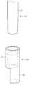
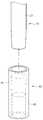
도 2는 본 발명의 제1 실시예에 따른 치과용 임플란트의 각도 조절도구의 결합상태를 나타내는 사시도,
도 3은 본 발명의 제1 실시예에 따른 치과용 임플란트의 각도 조절도구의 분리상태를 나타내는 사시도,
도 4는 본 발명의 제1 실시예에 따른 치과용 임플란트의 각도 조절도구의 결합상태를 나타내는 단면도,
도 5는 본 발명의 제1 실시예에 따른 치과용 임플란트의 각도 조절도구의 분리상태를 나타내는 단면도,
도 6은 본 발명의 제1 실시예에 따른 치과용 임플란트의 각도 조절도구를 사용하여 일체형 임플란트의 각도를 조절하는 방법을 설명하기 위한 도면,
도 7은 본 발명의 제1 실시예의 변형예에 따른 치과용 임플란트의 각도 조절도구의 분리상태를 나타내는 사시도,
도 8은 본 발명의 제2 실시예에 따른 치과용 임플란트의 각도 조절도구의 단면도, 그리고
도 9는 본 발명의 제2 실시예의 변형예에 따른 치과용 임플란트의 각도 조절도구의 단면도이다.1 is a side view of an integral implant according to the prior art,
FIG. 2 is a perspective view showing a combined state of the angle adjusting tool of the dental implant according to the first embodiment of the present invention, FIG.
FIG. 3 is a perspective view illustrating a separation state of the angle adjusting tool of the dental implant according to the first embodiment of the present invention, FIG.
FIG. 4 is a cross-sectional view showing a combined state of the angle adjusting tool of the dental implant according to the first embodiment of the present invention,
FIG. 5 is a sectional view showing a separated state of the angle adjusting tool of the dental implant according to the first embodiment of the present invention, FIG.
6 is a view for explaining a method of adjusting the angle of the integral implant using the angle adjusting tool of the dental implant according to the first embodiment of the present invention,
FIG. 7 is a perspective view showing a state of separation of an angle adjusting tool of a dental implant according to a modification of the first embodiment of the present invention; FIG.
8 is a cross-sectional view of an angle adjusting tool of a dental implant according to a second embodiment of the present invention, and
9 is a cross-sectional view of an angle adjusting tool of a dental implant according to a modification of the second embodiment of the present invention.
이하, 본 발명의 실시예에 따른 치과용 임플란트의 각도 조절도구를, 도면을 참조하여 상세하게 설명한다.DETAILED DESCRIPTION OF THE PREFERRED EMBODIMENTS Hereinafter, an angle adjusting tool of a dental implant according to an embodiment of the present invention will be described in detail with reference to the drawings.
본 발명의 실시예에 따른 치과용 임플란트의 각도 조절도구는, 임플란트의 식립 후에도 필요시 임플란트의 각도, 즉 픽스츄어(11)와 지대주(12) 사이의 각도를 조절할 수 있도록, 픽스츄어와 지대주 사이에 각도 조절이 가능한 오목부(13)를 형성한 일체형 임플란트(10)와 함께 사용될 수 있다.The angular adjustment tool of the dental implant according to the embodiment of the present invention can adjust the angle of the implant, that is, the angle between the
도 1 내지 도 6에 도시된 바와 같이, 본 발명의 제1 실시예에 따른 치과용 임플란트의 각도 조절도구는, 전술한 바와 같이 오목부(13)를 갖는 일체형 임플란트의 상부, 즉 지대주(12)에 결합시킨 상태로 시술자가 힘을 가해 임플란트의 각도를 조절할 수 있도록 하는 굽힘부재(20)와, 이 굽힘부재(20)에 착탈 가능하게 결합되며 각도 조절시 일체형 임플란트(10)의 외부표면에 맞닿아 더 이상의 각도 조절을 중지시키는 안내부재(30)를 포함한다.1 to 6, the angle adjusting tool of the dental implant according to the first embodiment of the present invention includes an upper portion of the monolithic implant having the
굽힘부재(20)는, 시술자가 파지하기 위한 원통형의 자루부(21)와, 일체형 임플란트(10)의 지대주(12)가 삽입되는 삽입부(22)를 포함한다. 삽입부(22)의 내부에는, 일체형 임플란트(10)의 지대주(12)의 형상에 대응되는 형상을 가져 지대주(12)의 상단 일부가 삽입될 수 있는 삽입구멍(23)이 형성된다.The
삽입구멍(23)에 지대주(12)가 완전히 삽입될 필요는 없으며, 시술자가 힘을 줄 수 있을 만큼 지대주(12)의 상단 일부가 삽입될 수 있으면 충분하다. 삽입구멍(23)은, 도 4 내지 도 6에 도시된 바와 같이 말단, 즉 삽입구멍(23)의 입구 쪽으로 갈수록 내경이 커지는 테이퍼 형상을 갖는다.It is not necessary that the
또한, 삽입부(22)의 외부는, 적어도 일부 구간에 걸쳐서 말단 쪽으로 갈수록 외경이 작아지는 테이퍼 형상을 갖는다. 그에 따라 삽입부(22)의 내부표면과 외부표면 사이의 두께는 말단 쪽으로 갈수록 점진적으로 얇아진다.The outside of the
안내부재(30)는, 굽힘부재(20)의 삽입부(22)가 끼워져 결합되는 끼움부(34)와, 이 끼움부(34)로부터 연장하는 멈춤부(35)를 포함한다.The
끼움부(34)는 전술한 바와 같이 테이퍼 형상을 갖는 굽힘부재(20)의 삽입부(22)에 대응되는 형상을 갖는다. 즉, 끼움부(34)의 내주면은 삽입부(22)에 대응되는 테이퍼 형상을 갖는다.The
멈춤부(35)는 끼움부(34)로부터 일정길이만큼 연장하며, 단면이 대략 반원 형상을 갖는다. 시술자가 힘을 가해 일체형 임플란트(10)의 각도를 조절할 때, 즉 일체형 임플란트의 오목부(13)를 구부릴 때, 픽스츄어(11)와 지대주(12) 사이의 각도가 사전에 정해진 각도에 도달하면 멈춤부(35)의 말단부분이 일체형 임플란트(10)의 외부표면에 맞닿아 더 이상 오목부(13)가 구부러질 수 없도록 되어 있다.The
이때, 멈춤부(35)의 말단부분이 맞닿는 일체형 임플란트(10)의 부분, 즉 픽스츄어(11)에 있어서 오목부(13)에 인접한 부분에는 나사산이 형성되지 않고 외부표면이 매끄럽거나 평평한 맞닿음부(14)가 형성될 수 있다. 도면에는 맞닿음부(14)가 복수의 평평한 표면을 가져, 마치 너트나 볼트 머리의 형상을 가지는 것처럼 도시되어 있지만, 이는 예시일 뿐이며, 맞닿음부(14)가 별도로 형성되지 않을 수도 있다.At this time, no thread is formed in the portion of the
멈춤부(35)의 길이가 달라지면 오목부(13)가 구부러지는 정도를 변화시킬 수 있다. 즉, 멈춤부(35)의 길이가 상대적으로 짧으면 멈춤부(35)의 말단부분이 맞닿음부(14)에 닿을 때까지 오목부(13)가 상대적으로 많이 구부러져야 하므로 지대주(12)의 중심축선은 픽스츄어의 중심축선에 대해 상대적으로 큰 각도를 갖는다. 역으로, 멈춤부(35)의 길이가 상대적으로 길면 멈춤부(35)의 말단부분이 맞닿음부(14)에 닿을 때까지 오목부(13)가 상대적으로 적게 구부러져야 하므로 지대주(12)의 중심축선은 픽스츄어의 중심축선에 대해 상대적으로 작은 각도를 갖는다. 따라서, 사전에 멈춤부(35)의 길이가 상이한 여러 개의 안내부재(30)를 제작하여 준비해 두고, 필요시 적절한 길이의 안내부재(30)를 선택적으로 사용하여 오목부(13)가 구부러지는 정도를 조절하여도 좋다.When the length of the
또, 도면에는 굽힘부재(20)의 삽입부(22)와 안내부재(30)의 끼움부(34) 사이에 아무런 결합수단이 없는 것으로 도시되어 있지만, 스냅식 결합 방식이나 나사식 체결 방식을 활용하여 우발적인 이탈을 방지하여도 좋다. 나사식 체결 방식을 활용하여, 삽입부(22)의 외주에 숫나사부를 형성하고 끼움부(34)의 내주에 암나사부를 형성할 경우, 안내부재(30)의 끼움 깊이를 조절함에 따라 전술한 바와 같이 멈춤부(35)의 길이가 상이해지는 것과 동일한 효과를 거둘 수도 있다.Although the figure shows that there is no coupling means between the
도 6에는 본 실시예에 따른 치과용 임플란트의 각도 조절도구를 사용하여 시술을 행하는 과정이 도시되어 있다.FIG. 6 shows a procedure of performing an operation using the angle adjusting tool of the dental implant according to the present embodiment.
우선, 도 6의 (a)에 도시된 바와 같이, 시술자는 굽힘부재(20)와 안내부재(30)를 결합시킨 상태에서 굽힘부재(20)의 삽입부(22) 내에 형성된 삽입구멍(23)에 일체형 임플란트(10)의 지대주(12)를 삽입한다.6 (a), the practitioner inserts the
계속해서 도 6의 (b)에 도시된 바와 같이, 시술자는 굽힘부재(20)에 힘을 가하여 안내부재(30)의 멈춤부(35)가 일체형 임플란트(10)의 맞닿음부(14)에 닿을 때까지 오목부(13)를 구부린다. 이때 픽스츄어(11)는 골(B) 내에 식립되어 고정된 상태이므로, 시술자는 지대주(12)에만 힘을 가하여 오목부(13)를 구부릴 수 있다.6 (b), the practitioner applies a force to the bending
도 6의 (c)에 도시된 바와 같이, 임플란트의 각도 조절이 완료되면 지대주(12)로부터 각도 조절도구를 분리시킨다.As shown in Fig. 6 (c), when the angle adjustment of the implant is completed, the angle adjusting tool is detached from the
이와 같이, 본 발명의 제1 실시예에 의하면, 시술자가 힘을 가해 임플란트의 각도를 조절할 때, 치과용 임플란트의 각도 조절도구가 임플란트의 외부표면과 맞닿아 필요 이상으로 임플란트의 오목부가 지나치게 구부러지는 것을 방지할 수 있어, 임플란트의 오목부가 파절되는 것을 방지할 수 있게 된다. 또, 임플란트의 각도를 시술자가 원하는 각도로 정확하게 맞출 수 있게 된다.
As described above, according to the first embodiment of the present invention, when the practitioner applies force to adjust the angle of the implant, the angle adjusting tool of the dental implant abuts the outer surface of the implant so that the concave portion of the implant is excessively bent It is possible to prevent the concave portion of the implant from being broken. In addition, the angle of the implant can be precisely adjusted to the angle desired by the operator.
도 7에는 본 발명의 제1 실시예의 변형예에 따른 치과용 임플란트의 각도 조절도구가 도시되어 있다. 제1 실시예의 변형예에 따른 치과용 임플란트의 각도 조절도구는, 전술한 제1 실시예에서와 마찬가지로, 지대주(12)에 결합시킨 상태로 시술자가 힘을 가해 임플란트의 각도를 조절할 수 있도록 하는 굽힘부재(20)와, 이 굽힘부재(20)에 착탈 가능하게 결합되며 각도 조절시 일체형 임플란트(10)의 외부표면에 맞닿아 더 이상의 각도 조절을 중지시키는 안내부재(40)를 포함한다.FIG. 7 shows a dental implant angle adjusting tool according to a modification of the first embodiment of the present invention. The angle adjusting tool of the dental implant according to the modified example of the first embodiment is a device for adjusting the angle of the implant by applying a force to the implant so as to adjust the angle of the implant in a state of being coupled to the
또한, 제1 실시예의 변형예에 있어서도, 안내부재(40)는, 굽힘부재(20)의 삽입부(22)가 끼워져 결합되는 끼움부(44)와, 이 끼움부(44)로부터 연장하는 멈춤부(45)를 포함한다는 점에서는 제1 실시예에서와 마찬가지이다.Also in the modification of the first embodiment, the
다만, 안내부재(40)의 멈춤부(45)가, 전술한 제1 실시예에서는 단면이 원호 형상을 가지도록 만들어지는 것에 비해, 제1 실시예의 변형예에서는 단면이 완전한 원 형상을 가지도록 만들어진다는 점에서 차이가 있다. 그에 따라 제1 실시예의 변형예에 따른 안내부재(40)는 외부의 형상이 전체적으로 원통형상을 갖는다.However, the
제1 실시예에서와 같은 안내부재(30)를 사용할 경우에는 지대주(12)에 각도 조절도구를 끼우기 전에 어느 방향으로 힘을 가할 것인지를 생각하고, 안내부재(30)의 멈춤부(35)가 구부러지는 쪽으로 위치하도록 방향을 맞춰 주어야 한다. 하지만, 제1 실시예의 변형예에서와 같은 원통형의 안내부재(40)를 사용할 경우, 지대주(12)에 각도 조절도구를 끼우기 전에 구부릴 방향을 미리 감안할 필요가 없이, 아무 방향으로나 힘을 가할 수 있어 편리하다.When the
제1 실시예의 변형예에 따른 치과용 임플란트의 각도 조절도구는, 멈춤부(45)의 형상 이외에는 전술한 제1 실시예와 동일하므로, 편의상 동일한 부분에 대한 상세한 설명은 생략한다.
The angle adjusting tool of the dental implant according to the modification of the first embodiment is the same as that of the first embodiment except for the shape of the
도 8에는 본 발명의 제2 실시예에 따른 치과용 임플란트의 각도 조절도구가 도시되어 있다. 제2 실시예에 따른 치과용 임플란트의 각도 조절도구는, 전술한 제1 실시예에서와 마찬가지로, 지대주(12)에 결합시킨 상태로 시술자가 힘을 가해 임플란트의 각도를 조절할 수 있도록 하는 굽힘부재(50)와, 이 굽힘부재(50)에 착탈 가능하게 결합되며 각도 조절시 일체형 임플란트(10)의 외부표면에 맞닿아 더 이상의 각도 조절을 중지시키는 안내부재(60)를 포함한다.8 shows a dental implant angle adjustment tool according to a second embodiment of the present invention. The angular adjustment tool of the dental implant according to the second embodiment is similar to that of the first embodiment described above except that the angular adjustment tool of the dental implant according to the second embodiment includes a bending member And a
다만, 굽힘부재와 안내부재가 전술한 제1 실시예에서는 별개의 부품으로 제작되어 서로 착탈 가능하게 결합되는 것과는 달리, 제2 실시예에서는 굽힘부재(50)와 안내부재(60)가 일체로 제작된다. 따라서, 제2 실시예의 각도 조절기구에서는, 굽힘부재(50)와 안내부재(60) 사이의 결합을 위한 구성이 필요하지 않게 된다.However, unlike the first embodiment in which the bending member and the guide member are separately formed and detachably coupled to each other, in the second embodiment, the bending
제2 실시예에 따른 굽힘부재(50)는, 시술자가 파지하기 위한 원통형의 자루부(21)와, 일체형 임플란트(10)의 지대주(12)가 삽입되는 삽입부(52)를 포함한다. 삽입부(52)의 내부에는, 일체형 임플란트(10)의 지대주(12)의 형상에 대응되는 형상을 가져 지대주(12)의 상단 일부가 삽입될 수 있는 삽입구멍(53)이 형성된다.The bending
전술한 제1 실시예에서와 마찬가지로, 삽입구멍(53)에 지대주(12)가 완전히 삽입될 필요는 없으며, 시술자가 힘을 줄 수 있을 만큼 지대주(12)의 상단 일부가 삽입될 수 있으면 충분하다. 삽입구멍(53)은, 도 8에 도시된 바와 같이 말단, 즉 삽입구멍(53)의 입구 쪽으로 갈수록 내경이 커지는 테이퍼 형상을 갖는다.It is not necessary that the
제2 실시예에 따른 안내부재(60)는, 굽힘부재(50)의 삽입부(52)로부터 연장하는 멈춤부(65)를 포함한다.The
전술한 제1 실시예에서와 마찬가지로, 멈춤부(65)는 삽입부(52)로부터 일정길이만큼 연장하며, 단면이 대략 반원 형상을 갖는다. 시술자가 힘을 가해 일체형 임플란트(10)의 각도를 조절할 때, 즉 일체형 임플란트의 오목부(13)를 구부릴 때, 픽스츄어(11)와 지대주(12) 사이의 각도가 사전에 정해진 각도에 도달하면 멈춤부(52)의 말단부분이 일체형 임플란트(10)의 외부표면에 맞닿아 더 이상 오목부(13)가 구부러질 수 없도록 되어 있다.As in the first embodiment described above, the
제1 실시예에서와 같이 굽힘부재(20)와 안내부재(30)가 착탈 가능하게 결합되는 경우에는, 시술 도중에 우발적으로 결합상태가 해제되지 않도록 주의를 기울어야 한다. 하지만, 제2 실시예에서와 같은 일체형 각도 조절도구를 사용할 경우에는, 결합상태가 해제될 우려가 없어 시술이 편리해 질 수 있다.
When the bending
도 9에는 본 발명의 제2 실시예의 변형예에 따른 치과용 임플란트의 각도 조절도구가 도시되어 있다. 제2 실시예의 변형예에 따른 치과용 임플란트의 각도 조절도구는, 전술한 제2 실시예에서와 마찬가지로, 지대주(12)에 결합시킨 상태로 시술자가 힘을 가해 임플란트의 각도를 조절할 수 있도록 하는 굽힘부재(50)와, 이 굽힘부재(50)와 일체로 형성되며 각도 조절시 일체형 임플란트(10)의 외부표면에 맞닿아 더 이상의 각도 조절을 중지시키는 안내부재(70)를 포함한다.Fig. 9 shows a dental implant angle adjustment tool according to a modification of the second embodiment of the present invention. The angle adjusting tool of the dental implant according to the modification of the second embodiment is similar to that of the above-described second embodiment in that the angle adjusting means of the dental implant is bent And a guide member 70 formed integrally with the bending
또한, 제2 실시예의 변형예에 있어서도, 안내부재(70)는, 삽입부(52)로부터 연장하는 멈춤부(75)를 포함한다는 점에서는 제2 실시예에서와 마찬가지이다.Also in the modified example of the second embodiment, the guide member 70 is the same as that in the second embodiment in that it includes a stopper portion 75 extending from the
다만, 안내부재(70)의 멈춤부(75)가, 전술한 제2 실시예에서는 단면이 원호 형상을 가지도록 만들어지는 것에 비해, 제2 실시예의 변형예에서는 단면이 완전한 원 형상을 가지도록 만들어진다는 점에서 차이가 있다. 그에 따라 제2 실시예의 변형예에 따른 안내부재(70)는 외부의 형상이 전체적으로 원통형상을 갖는다.However, the stop portion 75 of the guide member 70 is made to have an arc shape in cross section in the above-described second embodiment, whereas in the modification of the second embodiment, the cross section is made to have a complete circular shape There is a difference in the point. Accordingly, the guide member 70 according to the modified example of the second embodiment has a cylindrical shape as a whole.
제2 실시예에서와 같은 안내부재(60)를 갖는 각도조절기구를 사용할 경우에는 지대주(12)에 각도 조절도구를 끼우기 전에 어느 방향으로 힘을 가할 것인지를 생각하고, 안내부재(60)의 멈춤부(65)가 구부러지는 쪽으로 위치하도록 방향을 맞춰 주어야 한다. 하지만, 제2 실시예의 변형예에서와 같은 원통형의 안내부재(70)를 사용할 경우, 지대주(12)에 각도 조절도구를 끼우기 전에 구부릴 방향을 미리 감안할 필요가 없이, 아무 방향으로나 힘을 가할 수 있어 편리하다.In the case of using the angle adjusting mechanism having the
제2 실시예의 변형예에 따른 치과용 임플란트의 각도 조절도구는, 멈춤부(75)의 형상 이외에는 전술한 제2 실시예와 동일하므로, 편의상 동일한 부분에 대한 상세한 설명은 생략한다.The angle adjusting tool of the dental implant according to the modification of the second embodiment is the same as the second embodiment except for the shape of the stopper 75. Therefore, detailed description of the same parts will be omitted for the sake of convenience.
이상과 같이 본 발명을 예시된 도면을 참조하여 설명하였으나, 본 발명은 이상에서 설명된 실시예와 도면에 의해 한정되지 않으며, 특허청구범위 내에서 본 발명이 속하는 기술분야에서 통상의 지식을 가진 자들에 의해 다양한 수정 및 변형이 이루어질 수 있음은 물론이다.While the present invention has been particularly shown and described with reference to exemplary embodiments thereof, it is clearly understood that the same is by way of illustration and example only and is not to be taken by way of limitation, Various modifications and changes may be made by those skilled in the art.
10: (일체형) 임플란트
11: 픽스츄어
12: 지대주
13: 오목부
14: 맞닿음부
20: 굽힘부재
21: 자루부
22: 삽입부
23: 삽입구멍
30, 40: 안내부재
34, 44: 끼움부
35, 45: 멈춤부10: (one piece) Implant
11: Fixture
12: abutment
13:
14:
20:
21:
22:
23: Insertion hole
30, 40: guide member
34, 44:
35, 45:
Claims (12)
Translated fromKorean상기 지대주에 결합시킨 상태로 시술자가 힘을 가해 상기 임플란트의 각도를 조절할 수 있도록 하는 굽힘부재와;
상기 굽힘부재로부터 연장하며 각도 조절시 상기 임플란트의 외부표면에 맞닿아 각도 조절을 중지시키는 안내부재; 를 포함하며,
상기 굽힘부재는 상기 지대주가 삽입되는 삽입부를 포함하며, 상기 안내부재는 상기 삽입부로부터 연장하여 각도 조절시 상기 임플란트의 외부표면에 맞닿는 멈춤부를 포함하는, 치과용 임플란트의 각도 조절도구.An angle adjusting tool for adjusting an angle of a dental implant having a concave portion capable of adjusting an angle between a fixture and an abutment,
A bending member for allowing an operator to adjust the angle of the implant by applying force to the abutment;
A guide member extending from the bending member and contacting the outer surface of the implant when the angle is adjusted to stop the angle adjustment; / RTI >
Wherein the bending member includes an insertion portion into which the abutment is inserted and the guide member includes a stop extending from the insertion portion and abutting against the outer surface of the implant when the angle is adjusted.
상기 삽입부의 내부에는 상기 지대주의 형상에 대응되는 형상을 가져 상기 지대주의 적어도 일부가 삽입될 수 있는 삽입구멍이 형성되는, 치과용 임플란트의 각도 조절도구.The method according to claim 1,
Wherein an insertion hole is formed in the insertion portion so as to have a shape corresponding to the shape of the abutment and at least a part of the abutment can be inserted.
상기 삽입구멍은 상기 삽입부의 말단 쪽으로 갈수록 내경이 커지는 테이퍼 형상을 갖는, 치과용 임플란트의 각도 조절도구.The method of claim 2,
Wherein the insertion hole has a tapered shape whose inner diameter increases toward the distal end of the insertion portion.
상기 멈춤부는 단면이 원호 형상을 갖는, 치과용 임플란트의 각도 조절도구.The method according to claim 1,
Wherein the stop has an arcuate cross-section.
상기 멈춤부는 단면이 원 형상을 갖는, 치과용 임플란트의 각도 조절도구.The method according to claim 1,
Wherein the stop has a circular cross-section.
상기 굽힘부재와 상기 안내부재는 착탈 가능하게 결합되는, 치과용 임플란트의 각도 조절도구.The method according to claim 1,
Wherein the bending member and the guide member are detachably coupled to each other.
상기 삽입부의 외부는 적어도 일부 구간에 걸쳐서 말단 쪽으로 갈수록 외경이 작아지는 테이퍼 형상을 갖는, 치과용 임플란트의 각도 조절도구.The method of claim 6,
Wherein the outer portion of the insertion portion has a tapered shape having an outer diameter smaller toward the distal end over at least a part of the section.
상기 안내부재는, 상기 굽힘부재가 끼워져 결합되며 상기 멈춤부가 연장하기 시작하는 끼움부를 더 포함하는, 치과용 임플란트의 각도 조절도구.The method of claim 6,
Wherein the guide member further comprises a fit portion in which the bending member is fitted and engaged and the stop portion begins to extend.
상기 끼움부의 내부는 적어도 일부 구간에 걸쳐서 상기 멈춤부 쪽으로 갈수록 내경이 작아지는 테이퍼 형상을 갖는, 치과용 임플란트의 각도 조절도구.The method of claim 8,
Wherein the inside of the fitting portion has a tapered shape having an inner diameter reduced toward the stop portion over at least a part of the section.
상기 굽힘부재와 상기 안내부재는 일체로 형성되는, 치과용 임플란트의 각도 조절도구.The method according to claim 1,
Wherein the bending member and the guide member are integrally formed.
시술자가 파지할 수 있는 자루부와;
상기 자루부로부터 일체로 연장하며 상기 임플란트의 지대주가 삽입될 수 있는 삽입구멍을 갖춘 삽입부와;
상기 삽입부에 착탈 가능하게 결합되는 끼움부와;
상기 끼움부로부터 일체로 연장하며 각도 조절시 상기 임플란트의 외부표면에 맞닿아 각도 조절을 중지시키는 안내부재; 를 포함하는, 치과용 임플란트의 각도 조절도구.An angle adjusting tool for adjusting an angle of a dental implant having a concave portion capable of adjusting an angle between a fixture and an abutment,
A bag portion which the operator can grasp;
An insertion portion extending integrally from the bag portion and having an insertion hole into which the abutment of the implant can be inserted;
An insertion portion detachably coupled to the insertion portion;
A guide member extending integrally from the fitting portion and contacting the outer surface of the implant when the angle is adjusted to stop the angle adjustment; Wherein the dental implant has an angular orientation.
시술자가 파지할 수 있는 자루부와;
상기 자루부로부터 일체로 연장하며 상기 임플란트의 지대주가 삽입될 수 있는 삽입구멍을 갖춘 삽입부와;
상기 삽입부로부터 일체로 연장하며 각도 조절시 상기 임플란트의 외부표면에 맞닿아 각도 조절을 중지시키는 멈춤부; 를 포함하는, 치과용 임플란트의 각도 조절도구.An angle adjusting tool for adjusting an angle of a dental implant having a concave portion capable of adjusting an angle between a fixture and an abutment,
A bag portion which the operator can grasp;
An insertion portion extending integrally from the bag portion and having an insertion hole into which the abutment of the implant can be inserted;
A stop extending integrally from the insertion portion and abutting the outer surface of the implant when the angle is adjusted to stop the angle adjustment; Wherein the dental implant has an angular orientation.
Priority Applications (1)
| Application Number | Priority Date | Filing Date | Title |
|---|---|---|---|
| KR1020140027894AKR101525397B1 (en) | 2014-03-10 | 2014-03-10 | Tool for adjusting an angle of a dental implant |
Applications Claiming Priority (1)
| Application Number | Priority Date | Filing Date | Title |
|---|---|---|---|
| KR1020140027894AKR101525397B1 (en) | 2014-03-10 | 2014-03-10 | Tool for adjusting an angle of a dental implant |
Publications (1)
| Publication Number | Publication Date |
|---|---|
| KR101525397B1true KR101525397B1 (en) | 2015-06-03 |
Family
ID=53505248
Family Applications (1)
| Application Number | Title | Priority Date | Filing Date |
|---|---|---|---|
| KR1020140027894AActiveKR101525397B1 (en) | 2014-03-10 | 2014-03-10 | Tool for adjusting an angle of a dental implant |
Country Status (1)
| Country | Link |
|---|---|
| KR (1) | KR101525397B1 (en) |
Cited By (2)
| Publication number | Priority date | Publication date | Assignee | Title |
|---|---|---|---|---|
| KR20190057518A (en)* | 2017-11-20 | 2019-05-29 | 김주식 | Implant assembly and method thereof |
| KR20210002667U (en)* | 2020-05-26 | 2021-12-06 | 콴린 우 | One-piece formed abutment tooth capable of being adjusted angle thereof |
Citations (3)
| Publication number | Priority date | Publication date | Assignee | Title |
|---|---|---|---|---|
| US5312255A (en)* | 1989-06-05 | 1994-05-17 | Ernst Bauer | Screw implant for a jawbone |
| KR20000067899A (en)* | 1996-07-18 | 2000-11-25 | 윌리엄 에이치. 로스 | Abutment-mount system for dental implants |
| KR200425721Y1 (en)* | 2006-06-23 | 2006-09-06 | 오스템임플란트 주식회사 | Abutment Gage |
- 2014
- 2014-03-10KRKR1020140027894Apatent/KR101525397B1/enactiveActive
Patent Citations (3)
| Publication number | Priority date | Publication date | Assignee | Title |
|---|---|---|---|---|
| US5312255A (en)* | 1989-06-05 | 1994-05-17 | Ernst Bauer | Screw implant for a jawbone |
| KR20000067899A (en)* | 1996-07-18 | 2000-11-25 | 윌리엄 에이치. 로스 | Abutment-mount system for dental implants |
| KR200425721Y1 (en)* | 2006-06-23 | 2006-09-06 | 오스템임플란트 주식회사 | Abutment Gage |
Cited By (4)
| Publication number | Priority date | Publication date | Assignee | Title |
|---|---|---|---|---|
| KR20190057518A (en)* | 2017-11-20 | 2019-05-29 | 김주식 | Implant assembly and method thereof |
| KR102068525B1 (en) | 2017-11-20 | 2020-01-21 | 김주식 | Implant assembly and method thereof |
| KR20210002667U (en)* | 2020-05-26 | 2021-12-06 | 콴린 우 | One-piece formed abutment tooth capable of being adjusted angle thereof |
| KR200495903Y1 (en) | 2020-05-26 | 2022-09-15 | 콴린 우 | One-piece formed abutment tooth capable of being adjusted angle thereof |
Similar Documents
| Publication | Publication Date | Title |
|---|---|---|
| JP6301247B2 (en) | System and method for joints of dental implants and abutments for restoration | |
| EP2934367B1 (en) | Abutment | |
| KR101570615B1 (en) | Fixture remover for implant | |
| JP4694453B2 (en) | Healing abutment pillar | |
| JP6527143B2 (en) | Dental implant replica | |
| JP6360615B2 (en) | Fixed hybrid dental attachment assembly and method of use thereof | |
| EP3421004A1 (en) | Detachable implant-coupling prosthesis | |
| KR101943437B1 (en) | Abutment assembly and Method for assembling the same | |
| JP2019529047A (en) | System for connecting a dental restoration to a dental implant | |
| JP2017525437A (en) | Temporary prosthetic system and usage of the temporary prosthetic system | |
| JPH0780002A (en) | Implant fixture and pincers for implant fixture | |
| KR101419832B1 (en) | Material holder for implant and manufacturing apparatus having the same | |
| TWI644656B (en) | Implant structure and abutment | |
| KR20210131600A (en) | Coupling Assembly for Dental Implant Prosthesis | |
| KR20210030821A (en) | Dental orthodontic appliance indirect bonding device | |
| JP2017196363A (en) | Abutment separation tool | |
| KR102470652B1 (en) | Implant impression coping with improved connecting structure | |
| KR101525397B1 (en) | Tool for adjusting an angle of a dental implant | |
| EP2907473B1 (en) | Palatal implant for overdenture | |
| KR20160126584A (en) | Bi-acceptable abutment for dental implant | |
| KR101515790B1 (en) | fitting jig for healing abutment | |
| CN109069234B (en) | Handling tool, dental kit and method for assembling dental components | |
| KR101498197B1 (en) | Tool for adjusting an angle of a dental implant | |
| KR101067484B1 (en) | Impression Coping for Implant Procedures | |
| KR102208219B1 (en) | Dental implant assembly |
Legal Events
| Date | Code | Title | Description |
|---|---|---|---|
| PA0109 | Patent application | Patent event code:PA01091R01D Comment text:Patent Application Patent event date:20140310 | |
| PA0201 | Request for examination | ||
| E701 | Decision to grant or registration of patent right | ||
| PE0701 | Decision of registration | Patent event code:PE07011S01D Comment text:Decision to Grant Registration Patent event date:20150521 | |
| GRNT | Written decision to grant | ||
| PR0701 | Registration of establishment | Comment text:Registration of Establishment Patent event date:20150528 Patent event code:PR07011E01D | |
| PR1002 | Payment of registration fee | Payment date:20150528 End annual number:3 Start annual number:1 | |
| PG1601 | Publication of registration | ||
| FPAY | Annual fee payment | Payment date:20180323 Year of fee payment:4 | |
| PR1001 | Payment of annual fee | Payment date:20180323 Start annual number:4 End annual number:4 | |
| PR1001 | Payment of annual fee | Payment date:20200325 Start annual number:6 End annual number:6 | |
| PR1001 | Payment of annual fee | Payment date:20210426 Start annual number:7 End annual number:7 | |
| PR1001 | Payment of annual fee | Payment date:20220425 Start annual number:8 End annual number:8 | |
| PR1001 | Payment of annual fee | Payment date:20240325 Start annual number:10 End annual number:10 | |
| PR1001 | Payment of annual fee | Payment date:20250422 Start annual number:11 End annual number:11 |