KR101525008B1 - Connector for aluminium profile - Google Patents
Connector for aluminium profileDownload PDFInfo
- Publication number
- KR101525008B1 KR101525008B1KR1020140068144AKR20140068144AKR101525008B1KR 101525008 B1KR101525008 B1KR 101525008B1KR 1020140068144 AKR1020140068144 AKR 1020140068144AKR 20140068144 AKR20140068144 AKR 20140068144AKR 101525008 B1KR101525008 B1KR 101525008B1
- Authority
- KR
- South Korea
- Prior art keywords
- fixing
- profile
- groove
- hole
- receiving groove
- Prior art date
- Legal status (The legal status is an assumption and is not a legal conclusion. Google has not performed a legal analysis and makes no representation as to the accuracy of the status listed.)
- Active
Links
- XAGFODPZIPBFFR-UHFFFAOYSA-NaluminiumChemical compound[Al]XAGFODPZIPBFFR-UHFFFAOYSA-N0.000title1
- 229910052782aluminiumInorganic materials0.000title1
- 239000004411aluminiumSubstances0.000title1
- 238000003825pressingMethods0.000claimsabstractdescription20
- 230000000149penetrating effectEffects0.000claimsabstractdescription3
- 238000003780insertionMethods0.000claimsdescription12
- 230000037431insertionEffects0.000claimsdescription12
- 238000000034methodMethods0.000claimsdescription3
- 230000008878couplingEffects0.000abstractdescription5
- 238000010168coupling processMethods0.000abstractdescription5
- 238000005859coupling reactionMethods0.000abstractdescription5
- 238000005520cutting processMethods0.000abstractdescription5
- 230000000694effectsEffects0.000abstractdescription3
- 238000012986modificationMethods0.000description3
- 230000004048modificationEffects0.000description3
- 238000005452bendingMethods0.000description1
- 238000010276constructionMethods0.000description1
- 238000004519manufacturing processMethods0.000description1
Images


Classifications
- F—MECHANICAL ENGINEERING; LIGHTING; HEATING; WEAPONS; BLASTING
- F16—ENGINEERING ELEMENTS AND UNITS; GENERAL MEASURES FOR PRODUCING AND MAINTAINING EFFECTIVE FUNCTIONING OF MACHINES OR INSTALLATIONS; THERMAL INSULATION IN GENERAL
- F16B—DEVICES FOR FASTENING OR SECURING CONSTRUCTIONAL ELEMENTS OR MACHINE PARTS TOGETHER, e.g. NAILS, BOLTS, CIRCLIPS, CLAMPS, CLIPS OR WEDGES; JOINTS OR JOINTING
- F16B7/00—Connections of rods or tubes, e.g. of non-circular section, mutually, including resilient connections
- F16B7/18—Connections of rods or tubes, e.g. of non-circular section, mutually, including resilient connections using screw-thread elements
- F16B7/187—Connections of rods or tubes, e.g. of non-circular section, mutually, including resilient connections using screw-thread elements with sliding nuts or other additional connecting members for joining profiles provided with grooves or channels
- F—MECHANICAL ENGINEERING; LIGHTING; HEATING; WEAPONS; BLASTING
- F16—ENGINEERING ELEMENTS AND UNITS; GENERAL MEASURES FOR PRODUCING AND MAINTAINING EFFECTIVE FUNCTIONING OF MACHINES OR INSTALLATIONS; THERMAL INSULATION IN GENERAL
- F16B—DEVICES FOR FASTENING OR SECURING CONSTRUCTIONAL ELEMENTS OR MACHINE PARTS TOGETHER, e.g. NAILS, BOLTS, CIRCLIPS, CLAMPS, CLIPS OR WEDGES; JOINTS OR JOINTING
- F16B12/00—Jointing of furniture or the like, e.g. hidden from exterior
- F16B12/10—Jointing of furniture or the like, e.g. hidden from exterior using pegs, bolts, tenons, clamps, clips, or the like
- F16B12/28—Jointing of furniture or the like, e.g. hidden from exterior using pegs, bolts, tenons, clamps, clips, or the like for metal furniture parts
- F16B12/30—Jointing of furniture or the like, e.g. hidden from exterior using pegs, bolts, tenons, clamps, clips, or the like for metal furniture parts using threaded bolts
- F—MECHANICAL ENGINEERING; LIGHTING; HEATING; WEAPONS; BLASTING
- F16—ENGINEERING ELEMENTS AND UNITS; GENERAL MEASURES FOR PRODUCING AND MAINTAINING EFFECTIVE FUNCTIONING OF MACHINES OR INSTALLATIONS; THERMAL INSULATION IN GENERAL
- F16B—DEVICES FOR FASTENING OR SECURING CONSTRUCTIONAL ELEMENTS OR MACHINE PARTS TOGETHER, e.g. NAILS, BOLTS, CIRCLIPS, CLAMPS, CLIPS OR WEDGES; JOINTS OR JOINTING
- F16B12/00—Jointing of furniture or the like, e.g. hidden from exterior
- F16B12/40—Joints for furniture tubing
- F—MECHANICAL ENGINEERING; LIGHTING; HEATING; WEAPONS; BLASTING
- F16—ENGINEERING ELEMENTS AND UNITS; GENERAL MEASURES FOR PRODUCING AND MAINTAINING EFFECTIVE FUNCTIONING OF MACHINES OR INSTALLATIONS; THERMAL INSULATION IN GENERAL
- F16B—DEVICES FOR FASTENING OR SECURING CONSTRUCTIONAL ELEMENTS OR MACHINE PARTS TOGETHER, e.g. NAILS, BOLTS, CIRCLIPS, CLAMPS, CLIPS OR WEDGES; JOINTS OR JOINTING
- F16B12/00—Jointing of furniture or the like, e.g. hidden from exterior
- F16B12/44—Leg joints; Corner joints
- F16B12/50—Metal corner connections
Landscapes
- Engineering & Computer Science (AREA)
- General Engineering & Computer Science (AREA)
- Mechanical Engineering (AREA)
- Connection Of Plates (AREA)
- Mutual Connection Of Rods And Tubes (AREA)
Abstract
Translated fromKoreanDescription
Translated fromKorean본 발명은 프로파일용 고정구에 관한 것으로, 보다 구체적으로는 선반이나 프레임의 용도를 변경하는 경우에도 재구성의 용이성을 유지하면서 결합 강도가 증대되도록 하여 중하중에도 무리 없이 사용할 수 있는 프로파일용 고정구에 관한 것이다.The present invention relates to a profile fastener, and more particularly, to a profile fastener that can be used without difficulty even in middle and lower portions, by increasing the coupling strength while maintaining easiness of reconstruction even when the use of a shelf or frame is changed.
통상적으로, 프로파일은 경량이면서 강도가 높고 다양한 형태와 규격으로 표준화되어 경하중의 선반은 물론, 중하중의 기계장치 프레임에 이르기까지 활용도가 높다. 게다가 일단 설치된 프로파일 선반이나 프레임의 용도가 변경되는 경우에도 비교적 구조의 변경이 용이하고 기능성의 유지가 가능한 측면의 장점도 지닌다. 이러한 프로파일로 이루어진 조립체는 단순히 수직, 수평 방향의 조립만을 시행하는 것이 아니라 다양한 각도로 고정하여 조립체를 형성할 수 있어야 한다.Typically, profiles are lightweight, high in strength, standardized in a variety of shapes and sizes, and are highly utilized, ranging from heavy duty lathes to heavy duty machine frames. In addition, even when the use of the profile shelf or frame once installed is changed, the structure can be easily changed and the functionality can be maintained. The assembly of such profiles should be able to form an assembly by fixing at various angles, rather than merely performing vertical and horizontal assembly.
일예로, 한국 등록실용신안 제0407314호에 따르면, ‘판상의 벽체의 일측변부를 고정하기 위한 것으로, 다각기둥 형상의 프레임과 상기 프레임에 결합되는 지지부재를 포함하며, 상기 프레임은 상기 벽체의 일측면에 접촉되는 가이드면을 가지며, 상기 지지부재는, 상기 가이드면과 나란하게 배치되어 상기 벽체의 타측면에 접촉되는 지지면 가지는, 프로파일 조립체에 있어서, 상기 프레임은, 상기 가이드 면에 대해 돌출되고 상기 프레임의 길이방향에 대해 수직인 방향으로 서로 이격된 한 쌍의 돌출부를 구비하며, 상기 지지부재는 상기 지지면에 대해 돌출되고 상기 돌출부들 사이에 끼워지는 걸림부가 마련되어 있는 것을 특징으로 하는 프로파일 조립체.’를 제시한다.For example, Korean Utility Model Registration No. 0407314 discloses a method for fixing one side portion of a plate-shaped wall, comprising a prismatic frame and a support member coupled to the frame, Wherein the support member has a support surface disposed in parallel with the guide surface and in contact with the other side of the wall, wherein the frame is protruded relative to the guide surface And a pair of protrusions spaced from each other in a direction perpendicular to the longitudinal direction of the frame, wherein the support member is provided with a protrusion protruding from the support surface and sandwiched between the protrusions. .
하지만, 이러한 프로파일 조립체는 수직 또는 수평 방향의 조립만 가능한 구조로 다양한 각도 조절이 불가능한 문제가 발생한다.However, such a profile assembly can be assembled only vertically or horizontally, resulting in a problem that various angles can not be adjusted.
이에 따라 본 발명은 상기와 같은 종래의 문제점을 근본적으로 해결하기 위한 것으로서, 선반이나 프레임의 용도를 변경하는 경우에도 재구성의 용이성을 유지하면서 결합 강도가 증대되도록 하여 중하중에도 무리 없이 사용할 수 있는 프로파일용 고정구를 제공하려는데 그 목적이 있다.Accordingly, it is an object of the present invention to fundamentally solve the above-described problems of the prior art, and it is an object of the present invention to provide a method of manufacturing a profile that can be used without difficulty even under heavy load, The purpose is to provide a fixture.
이러한 목적을 달성하기 위해 본 발명은 요홈을 구비하는 한쌍의 제1, 2프로파일을 수직 방향으로 서로 결합하도록 구성된 프로파일용 고정구에 있어서: 상기 제1프로파일의 요홈 상에 길이방향으로 삽설 가능하면서 일측 하면에 수용홈과 수용홈에 수직 관통되는 관통공을 구비하고, 타측에 하부가 절삭된 절삭부를 개재하는 고정공을 구비하는 고정체; 상기 고정체의 수용홈과 관통공을 통해 요홈의 내측을 가압하여 고정체와 제1프로파일이 서로 고정되게 구비하는 가압수단; 및 상기 고정체의 고정공 상에 수용되어 제2프로파일의 요홈에 삽설된 고정너트와 체결되어 고정체와 제2프로파일이 서로 고정되게 체결볼트를 구비하는 고정수단;을 포함하여 이루어지는 것을 특징으로 한다.In order to achieve this object, the present invention provides a profile fixture configured to couple a pair of first and second profiles having a groove in a vertical direction, the profile fixture comprising: A fixing body having a receiving groove and a through hole vertically penetrating the receiving groove, and a fixing hole having a lower portion cut through the fixing hole; A pressing means for pressing the inside of the groove through the receiving groove and the through hole of the fixing body to fix the fixing body and the first profile to each other; And fixing means, which is accommodated in the fixing hole of the fixing member and is fastened to the fixing nut inserted in the groove of the second profile so that the fixing member and the second profile are fixed to each other, .
이때, 상기 고정체는 상부에 체결볼트가 고정너트와의 체결이 용이하게 경사홈을 더 구비하는 것을 특징으로 한다.At this time, the fixture further includes an inclined groove on the upper portion so that the fastening bolt can be easily fastened to the fixing nut.
또한, 상기 가압수단은 고정체의 수용홈에 내부에 삽설되는 삽입너트와, 상기 삽입너트에 체결되어 제1프로파일의 요홈 내측을 가압하게 가압부를 구비하는 탭볼트를 구비하는 것을 특징으로 한다.The pressing means includes an insertion nut inserted into the receiving groove of the fixture, and a tap bolt fastened to the insertion nut and having a pressing portion for pressing the inside of the groove of the first profile.
한편, 이에 앞서 본 명세서 및 특허청구범위에 사용된 용어나 단어는 통상적이거나 사전적인 의미로 한정해서 해석되어서는 아니 되며, 발명자는 그 자신의 발명을 가장 최선의 방법으로 설명하기 위해 용어의 개념을 적절하게 정의할 수 있다는 원칙에 입각하여 본 발명의 기술적 사상에 부합하는 의미와 개념으로 해석되어야만 한다. 따라서 본 명세서에 기재된 실시예와 도면에 도시된 구성은 본 발명의 가장 바람직한 일 실시예에 불과할 뿐이고, 본 발명의 기술적 사상을 모두 대변하는 것은 아니므로, 본 출원시점에 있어서 이들을 대체할 수 있는 다양한 균등물과 변형예들이 있을 수 있음을 이해하여야 한다.It should be understood, however, that the terminology or words of the present specification and claims should not be construed in an ordinary sense or in a dictionary, and that the inventors shall not be limited to the concept of a term It should be construed in accordance with the meaning and concept consistent with the technical idea of the present invention based on the principle that it can be properly defined. Therefore, the embodiments described in the present specification and the configurations shown in the drawings are merely the most preferred embodiments of the present invention, and not all of the technical ideas of the present invention are described. Therefore, It is to be understood that equivalents and modifications are possible.
이상의 구성 및 작용에서 설명한 바와 같이, 본 발명은 선반이나 프레임의 용도를 변경하는 경우에도 재구성의 용이성을 유지하면서 결합 강도가 증대되도록 하여 중하중에도 무리 없이 사용할 수 있는 효과를 제공한다.INDUSTRIAL APPLICABILITY As described in the above construction and operation, the present invention provides an effect that the coupling strength can be increased while maintaining easiness of reconstruction even when changing the use of the shelf or frame, so that it can be used without difficulty even in the middle and lower.
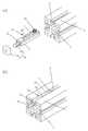
도 1은 본 발명에 따른 프로파일용 고정구를 나타내는 분해 사시도,
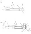
도 2a 내지 2c는 본 발명에 따른 프로파일용 고정구의 결합을 순차적으로 나타내는 사시도,
도 3은 본 발명에 따른 프로파일용 고정구를 나타내는 단면도,
도 4는 본 발명의 일실시예에 따른 프로파일용 고정구를 나타내는 하부 사시도.1 is an exploded perspective view showing a fixture for a profile according to the present invention,
Figs. 2A to 2C are perspective views sequentially showing engagement of the profile fastener according to the present invention,
3 is a cross-sectional view showing a fixing device for a profile according to the present invention,
4 is a bottom perspective view of a fixture for a profile according to an embodiment of the present invention.
이하, 첨부된 도면을 참조하여 본 발명에 따른 바람직한 실시예를 상세하게 설명한다.Hereinafter, preferred embodiments of the present invention will be described in detail with reference to the accompanying drawings.
도 1은 본 발명에 따른 프로파일용 고정구를 나타내는 분해 사시도이고, 도 2a 내지 2c는 본 발명에 따른 프로파일용 고정구의 결합을 순차적으로 나타내는 사시도이며, 도 3은 본 발명에 따른 프로파일용 고정구를 나타내는 단면도이다.FIG. 1 is an exploded perspective view showing a fixing device for a profile according to the present invention, FIGS. 2A to 2C are perspective views sequentially showing the coupling of the fixing device for a profile according to the present invention, and FIG. 3 is a sectional view showing the fixing device for a profile according to the present invention to be.
본 발명은 요홈(3)(4)을 구비하는 한쌍의 제1, 2프로파일(1)(2)을 수직 방향으로 서로 결합하도록 구성된 프로파일용 고정구에 관련되며, 고정체(10), 가압수단(20), 고정수단(30)을 주요 구성으로 한다.The present invention relates to a profile fixture configured to couple a pair of first and second profiles (1) (2) having recesses (3) (4) in a vertical direction with each other and comprising a fixture (10) 20), and fixing means (30).
본 발명에 따른 고정체(10)는 상기 제1프로파일(1)의 요홈(3) 상에 길이방향으로 삽설 가능하면서 일측 하면에 수용홈(11)과 수용홈(11)에 수직 관통되는 관통공(12)을 구비하고, 타측에 하부가 절삭된 절삭부(13a)를 개재하는 고정공(13)을 구비한다. 고정체(10)는 제1프로파일(1)의 요홈(3)에 삽설되어 이동이 가능하도록 구성되는 바, 요홈(3)에 형성된 단턱(4)과 맞닿아 이동할 수 있도록 돌부(16)가 형성하게 된다. 이러한, 고정체(10)는 중앙에 후술하는 체결볼트(32)를 도구에 의해 체결할 수 있도록 체결통공(18)이 형성되고, 일측 하면에 사각의 수용홈(11)을 구비하고, 상부 방향으로 서로 연통되는 관통공(12)을 구비하는 바, 여기서 일측이란 제1프로파일(1)의 요홈(3)에 최초 삽설되는 방향을 말한다. 그리고, 그 타측면에는 하부가 절삭된 절삭부(13a)를 개재하는 고정공(13)을 구비하는 바, 고정공(13)의 하부가 절삭된 절삭부(13a)를 통해 후술하는 체결볼트(32)의 삽입이 용이하도록 구성된다.The
또, 본 발명에 따른 가압수단(20)은 상기 고정체(10)의 수용홈(11)과 관통공(12)을 통해 요홈(3)의 내측을 가압하여 고정체(10)와 제1프로파일(1)이 서로 고정되게 구비한다. 가압수단(20)은 상술한 고정체(10)가 제1프로파일(1)의 요홈(3) 내부에 삽설된 상태로 고정체(10)의 수용홈(11)과 관통공(12)을 통해 상기 고정체(10)가 제1프로파일(1)에 고정될 수 있도록 구성된다.The pressing means 20 according to the present invention presses the inside of the
이때, 상기 가압수단(20)은 고정체(10)의 수용홈(11)에 내부에 삽설되는 삽입너트(21)와, 상기 삽입너트(21)에 체결되어 제1프로파일(1)의 요홈(2) 내측을 가압하게 가압부(22a)를 구비하는 탭볼트(22)를 구비하는 것을 특징으로 한다. 가압수단(20)은 고정체(10)를 제1프로파일(1) 상에 고정될 수 있도록 하는 역할을 수행하는 것으로 삽입너트(21)와 탭볼트(22)로 구성되는 바, 삽입너트(21)는 고정체(10)의 수용홈(11)에 삽설되고, 탭볼트(22)는 고정체(10)의 관통공(12)을 통해 삽입너트(21)와 체결하게 된다. 이때, 탭볼트(22)에 형성된 가압부(22a)를 통해 제1프로파일(1)의 요홈(2) 내측면을 가압하게 됨으로 고정체(10)는 제1프로파일(1) 상에 고정하게 된다.The pressing
또, 본 발명에 따른 고정수단(30)은 상기 고정체(10)의 고정공(13) 상에 수용되어 제2프로파일(2)의 요홈(4)에 삽설된 고정너트(31)와 체결되어 고정체(10)와 제2프로파일(2)이 서로 고정되게 체결볼트(32)를 구비한다. 고정수단(30)은 고정체(10)를 제2프로파일(2) 상에 고정될 수 있도록 하는 역할을 수행하는 것으로 고정너트(31)와 체결볼트(32)로 구성되는 바, 고정너트(31)는 제2프로파일(2)의 요홈(4) 상에 삽설되고, 체결볼트(32)는 고정체(10)의 고정공(13) 상에 수용되어 상기 고정너트(31)와 서로 체결하게 됨으로 고정너트(31)가 제2프로파일(2)의 요홈(4)을 가압하여 고정하게 된다.The fixing means 30 according to the present invention is fastened to a
이때, 상기 고정체(10)는 상부에 체결볼트(32)가 고정너트(31)와의 체결이 용이하게 경사홈(15)을 더 구비하는 것을 특징으로 한다. 고정체(10)는 상술한 고정수단(30)의 체결볼트(32)가 고정너트(31) 상에 체결될 수 있도록 도구를 사용하여 중앙에 형성된 체결통공(18)으로 체결볼트(32)를 회전시키게 되는 바, 체결볼트(32)를 회전시키기 위해서는 서로 수평 방향으로 평행되어야 하지만, 가압수단(20) 때문에 평행 상태가 되지 못하므로 경사홈(15)을 통해 체결볼트(32)를 용이하게 회전시킬 수 있도록 한다.At this time, the
도 4는 본 발명의 일실시예에 따른 프로파일용 고정구를 나타내는 하부 사시도이다.4 is a bottom perspective view illustrating a fixture for a profile according to one embodiment of the present invention.
이때, 상기 고정체(10)의 수용홈(11) 하부와 절삭부(13a)를 삽입너트(21)와 체결볼트(32)의 이탈을 방지하게 절곡하는 것을 특징으로 한다. 상기 수용홈(11)과 절삭부(13a)는 가압수단(20)의 체결볼트(32)와 고정수단(30)의 고정너트(31)를 수용한 상태로 수용홈(11) 하부와 절삭부(13a)를 가압하여 절곡 형성함에 따라 제1, 2프로파일(1)(2)의 고정이 수월해 질 수 있도록 한다. 즉, 제1, 2프로파일(1)(2)의 고정 시 체결볼트(32)와 고정너트(31)를 삽설한 상태로 서로 고정해야 하기 때문에 이탈을 방지한다.The lower portion of the receiving
도 1 내지 도 4를 참조하여 본 발명의 결합에 있어서, 고정체(10)의 일측 하면에 형성된 수용홈(11) 상에 삽입너트(21)를 수용한 상태로 고정체(10)를 제1프로파일(1)의 요홈(3)에 삽입시킨다. 그리고, 수용홈(11)에 수직 관통되는 관통공(12)에 탭볼트(22)를 삽입 시켜 삽입너트(21)와 완전히 체결하지 않은 상태로 두고, 고정체(10)의 타측에 하부가 절삭된 절삭부(13a)를 개재하는 고정공(13)을 상에 체결볼트(32)를 수용한 상태로 고정너트(31)를 제2프로파일(2)의 요홈(4)에 삽설하여 상기 체결볼트(32)와 서로 체결함에 따라 고정체(10)는 제2프로파일(2) 상에 고정되고, 상술한 탭볼트(22)를 삽입너트(21) 상에 완전히 체결함에 따라 가압부(22a)가 제1프로파일(1)의 요홈(2) 내측을 가압하여 고정하게 됨으로 제1, 2프로파일(1)(2)은 서로 고정하게 된다.1 to 4, the
이와 같이, 본 발명은 선반이나 프레임의 용도를 변경하는 경우에도 재구성의 용이성을 유지하면서 결합 강도가 증대되도록 하여 중하중에도 무리 없이 사용할 수 있는 효과를 제공한다.As described above, the present invention provides an effect that the coupling strength can be increased while maintaining the easiness of reconstruction even when the use of the shelf or the frame is changed, so that it can be used without difficulty even in the middle and lower.
본 발명은 기재된 실시예에 한정되는 것은 아니고, 본 발명의 사상 및 범위를 벗어나지 않고 다양하게 수정 및 변형할 수 있음은 이 기술의 분야에서 통상의 지식을 가진 자에게 자명하다. 따라서 그러한 변형예 또는 수정예들은 본 발명의 특허청구범위에 속한다 해야 할 것이다.It will be apparent to those skilled in the art that various modifications and variations can be made in the present invention without departing from the spirit and scope of the invention as defined by the appended claims. It is therefore intended that such variations and modifications fall within the scope of the appended claims.
1, 2: 제1, 2프로파일3, 4: 요홈
10: 고정체11: 수용홈
12: 관통공13: 고정공
13a: 절삭부15: 경사홈
16: 돌부18: 체결통공
20: 가압수단21: 삽입너트
22: 탭볼트22a: 가압부
30: 고정수단31: 고정너트
32: 체결볼트1, 2: first and
10: fixture 11: receiving groove
12: Through hole 13: Fixed hole
13a: cutting section 15: inclined groove
16: protrusion 18: fastening hole
20: pressing means 21: insertion nut
22:
30: fixing means 31: fixing nut
32: fastening bolt
Claims (3)
Translated fromKorean상기 제1프로파일(1)의 요홈(3) 상에 길이방향으로 삽설 가능하면서 일측 하면에 수용홈(11)과 수용홈(11)에 수직 관통되는 관통공(12)을 구비하고, 타측에 하부가 절삭된 절삭부(13a)를 개재하는 고정공(13)을 구비하는 고정체(10);
상기 고정체(10)의 수용홈(11)과 관통공(12)을 통해 요홈(3)의 내측을 가압하여 고정체(10)와 제1프로파일(1)이 서로 고정되게 구비하는 가압수단(20); 및
상기 고정체(10)의 고정공(13) 상에 수용되어 제2프로파일(2)의 요홈(4)에 삽설된 고정너트(31)와 체결되어 고정체(10)와 제2프로파일(2)이 서로 고정되게 체결볼트(32)를 구비하는 고정수단(30);을 포함하여 이루어지는 것을 특징으로 하는 프로파일용 고정구.A profile fastener configured to couple a pair of first and second profiles (1) (2) having recesses (3) (4) in a vertical direction with each other:
And a through hole 12 vertically penetrating the receiving groove 11 and the receiving groove 11 on one side of the groove 3 in the longitudinal direction on the groove 3 of the first profile 1, A fixture (10) having a fixing hole (13) through a cut portion (13a) cut thereon;
A pressing means for pressing the inside of the groove 3 through the receiving groove 11 and the through hole 12 of the fixing body 10 to fix the fixing body 10 and the first profile 1 to each other 20); And
And is fixed on the fixing hole 13 of the fixing body 10 and fastened to the fixing nut 31 inserted in the groove 4 of the second profile 2 to fix the fixing body 10 and the second profile 2, And fixing means (30) having fastening bolts (32) fixed to each other.
상기 고정체(10)는 상부에 체결볼트(32)가 고정너트(31)와의 체결이 용이하게 경사홈(15)을 더 구비하는 것을 특징으로 하는 프로파일용 고정구.The method according to claim 1,
Characterized in that the fixing body (10) further comprises an inclined groove (15) at the upper portion so that the fastening bolt (32) can be easily fastened to the fixing nut (31).
상기 가압수단(20)은 고정체(10)의 수용홈(11)에 내부에 삽설되는 삽입너트(21)와, 상기 삽입너트(21)에 체결되어 제1프로파일(1)의 요홈(2) 내측을 가압하게 가압부(22a)를 구비하는 탭볼트(22)를 구비하는 것을 특징으로 하는 프로파일용 고정구.The method according to claim 1,
The pressing means 20 includes an insertion nut 21 inserted in the receiving groove 11 of the fixing member 10 and a groove 21 formed in the groove 2 of the first profile 1, And a tab bolt (22) having a pressing portion (22a) to press the inside thereof.
Priority Applications (1)
| Application Number | Priority Date | Filing Date | Title |
|---|---|---|---|
| KR1020140068144AKR101525008B1 (en) | 2014-06-05 | 2014-06-05 | Connector for aluminium profile |
Applications Claiming Priority (1)
| Application Number | Priority Date | Filing Date | Title |
|---|---|---|---|
| KR1020140068144AKR101525008B1 (en) | 2014-06-05 | 2014-06-05 | Connector for aluminium profile |
Publications (1)
| Publication Number | Publication Date |
|---|---|
| KR101525008B1true KR101525008B1 (en) | 2015-06-03 |
Family
ID=53505204
Family Applications (1)
| Application Number | Title | Priority Date | Filing Date |
|---|---|---|---|
| KR1020140068144AActiveKR101525008B1 (en) | 2014-06-05 | 2014-06-05 | Connector for aluminium profile |
Country Status (1)
| Country | Link |
|---|---|
| KR (1) | KR101525008B1 (en) |
Cited By (3)
| Publication number | Priority date | Publication date | Assignee | Title |
|---|---|---|---|---|
| KR20200008865A (en)* | 2018-07-17 | 2020-01-29 | 박태열 | A device for connecting two profiles in orthogonal direction |
| KR20210068879A (en)* | 2019-12-02 | 2021-06-10 | 최미림 | Aluminium profile assembly |
| EP4484768A1 (en)* | 2023-06-28 | 2025-01-01 | Oelschläger Metalltechnik GmbH | Fixing connector for a detachable, preferably blunt, connection of a first hollow profile of a furniture frame |
Citations (4)
| Publication number | Priority date | Publication date | Assignee | Title |
|---|---|---|---|---|
| EP0490086B1 (en)* | 1990-12-13 | 1995-01-18 | Wolfgang Dipl.-Ing. Rixen | Threaded joint for at least two parts to be connected releasable to each other in particular profile bars provided with longitudinal slots |
| KR200250960Y1 (en)* | 2001-07-14 | 2001-11-17 | 훼스텍 주식회사 | joint device of profile |
| JP2005207458A (en)* | 2004-01-21 | 2005-08-04 | Matsushita Electric Works Ltd | Frame connecting structure |
| KR20130005337U (en)* | 2012-03-02 | 2013-09-11 | 김성우 | square fixing profile |
- 2014
- 2014-06-05KRKR1020140068144Apatent/KR101525008B1/enactiveActive
Patent Citations (4)
| Publication number | Priority date | Publication date | Assignee | Title |
|---|---|---|---|---|
| EP0490086B1 (en)* | 1990-12-13 | 1995-01-18 | Wolfgang Dipl.-Ing. Rixen | Threaded joint for at least two parts to be connected releasable to each other in particular profile bars provided with longitudinal slots |
| KR200250960Y1 (en)* | 2001-07-14 | 2001-11-17 | 훼스텍 주식회사 | joint device of profile |
| JP2005207458A (en)* | 2004-01-21 | 2005-08-04 | Matsushita Electric Works Ltd | Frame connecting structure |
| KR20130005337U (en)* | 2012-03-02 | 2013-09-11 | 김성우 | square fixing profile |
Cited By (5)
| Publication number | Priority date | Publication date | Assignee | Title |
|---|---|---|---|---|
| KR20200008865A (en)* | 2018-07-17 | 2020-01-29 | 박태열 | A device for connecting two profiles in orthogonal direction |
| KR102754368B1 (en)* | 2018-07-17 | 2025-01-14 | 박태열 | A device for connecting two profiles in orthogonal direction |
| KR20210068879A (en)* | 2019-12-02 | 2021-06-10 | 최미림 | Aluminium profile assembly |
| KR102282926B1 (en)* | 2019-12-02 | 2021-07-27 | 최미림 | Aluminium profile assembly |
| EP4484768A1 (en)* | 2023-06-28 | 2025-01-01 | Oelschläger Metalltechnik GmbH | Fixing connector for a detachable, preferably blunt, connection of a first hollow profile of a furniture frame |
Similar Documents
| Publication | Publication Date | Title |
|---|---|---|
| KR101509920B1 (en) | a coupling for aluminum profile | |
| US9051950B2 (en) | Universal panel clamp | |
| KR101335801B1 (en) | Connector for aluminium profile | |
| KR101285949B1 (en) | Connector for aluminium profile | |
| KR101137201B1 (en) | Connector for aluminium profile | |
| KR101525008B1 (en) | Connector for aluminium profile | |
| US20170077626A1 (en) | Battery terminal | |
| US20110147554A1 (en) | Holding device of fitments | |
| KR20150117388A (en) | a coupling for aluminum profile | |
| CN207776422U (en) | The holding appliance of scaffolding board | |
| KR101278828B1 (en) | Connector for aluminium profile | |
| KR101575569B1 (en) | Connector for aluminium profile | |
| US9156413B2 (en) | Fixing mount of bicycle carrier | |
| KR101933305B1 (en) | Connector for aluminium profile | |
| KR101115330B1 (en) | Connector for aluminium profile | |
| US9705122B2 (en) | Battery terminal with unintended deformation prevention features | |
| JP4960166B2 (en) | Withdrawal hardware | |
| KR101137211B1 (en) | Connector for aluminium profile | |
| KR200442669Y1 (en) | Fixtures on prefabricated shelves | |
| KR101137136B1 (en) | Connector for aluminium profile | |
| KR101509919B1 (en) | a coupling for aluminum profile | |
| CN203516397U (en) | Locking device and photovoltaic module assembly | |
| KR101605370B1 (en) | Connect apparatus of aluminum Profile | |
| KR101289135B1 (en) | Connector for aluminium profile | |
| KR101487734B1 (en) | assembly for furniture |
Legal Events
| Date | Code | Title | Description |
|---|---|---|---|
| PA0109 | Patent application | Patent event code:PA01091R01D Comment text:Patent Application Patent event date:20140605 | |
| PA0201 | Request for examination | ||
| E701 | Decision to grant or registration of patent right | ||
| PE0701 | Decision of registration | Patent event code:PE07011S01D Comment text:Decision to Grant Registration Patent event date:20150518 | |
| GRNT | Written decision to grant | ||
| PR0701 | Registration of establishment | Comment text:Registration of Establishment Patent event date:20150527 Patent event code:PR07011E01D | |
| PR1002 | Payment of registration fee | Payment date:20150527 End annual number:3 Start annual number:1 | |
| PG1601 | Publication of registration | ||
| FPAY | Annual fee payment | Payment date:20180526 Year of fee payment:4 | |
| PR1001 | Payment of annual fee | Payment date:20180526 Start annual number:4 End annual number:4 | |
| FPAY | Annual fee payment | Payment date:20191127 Year of fee payment:5 | |
| PR1001 | Payment of annual fee | Payment date:20191127 Start annual number:5 End annual number:5 | |
| PR1001 | Payment of annual fee | Payment date:20200726 Start annual number:6 End annual number:6 | |
| PR1001 | Payment of annual fee | Payment date:20221026 Start annual number:8 End annual number:8 | |
| PR1001 | Payment of annual fee | Payment date:20230821 Start annual number:9 End annual number:9 | |
| PR1001 | Payment of annual fee | Payment date:20240514 Start annual number:10 End annual number:10 |