KR101524892B1 - Inductive power providing system having moving outlets - Google Patents
Inductive power providing system having moving outletsDownload PDFInfo
- Publication number
- KR101524892B1 KR101524892B1KR1020107010227AKR20107010227AKR101524892B1KR 101524892 B1KR101524892 B1KR 101524892B1KR 1020107010227 AKR1020107010227 AKR 1020107010227AKR 20107010227 AKR20107010227 AKR 20107010227AKR 101524892 B1KR101524892 B1KR 101524892B1
- Authority
- KR
- South Korea
- Prior art keywords
- primary
- inductor
- inductive power
- primary coil
- power
- Prior art date
- Legal status (The legal status is an assumption and is not a legal conclusion. Google has not performed a legal analysis and makes no representation as to the accuracy of the status listed.)
- Active
Links
- 230000001939inductive effectEffects0.000titleclaimsabstractdescription71
- 230000007246mechanismEffects0.000claimsabstractdescription22
- 230000005291magnetic effectEffects0.000claimsdescription26
- 230000005855radiationEffects0.000claimsdescription22
- 238000000034methodMethods0.000claimsdescription12
- 230000033001locomotionEffects0.000claimsdescription7
- 239000010410layerSubstances0.000description42
- 239000010440gypsumSubstances0.000description32
- 229910052602gypsumInorganic materials0.000description32
- 239000002344surface layerSubstances0.000description19
- 239000000853adhesiveSubstances0.000description16
- 230000001070adhesive effectEffects0.000description14
- 239000004020conductorSubstances0.000description13
- 239000000123paperSubstances0.000description12
- 230000008878couplingEffects0.000description11
- 238000010168coupling processMethods0.000description11
- 238000005859coupling reactionMethods0.000description11
- 230000006698inductionEffects0.000description11
- 239000000463materialSubstances0.000description11
- 230000005540biological transmissionEffects0.000description10
- 238000010586diagramMethods0.000description10
- 230000004907fluxEffects0.000description9
- 239000003990capacitorSubstances0.000description7
- 239000011248coating agentSubstances0.000description7
- 238000000576coating methodMethods0.000description7
- 230000002265preventionEffects0.000description6
- 206010014357Electric shockDiseases0.000description5
- 239000004575stoneSubstances0.000description5
- 230000001413cellular effectEffects0.000description4
- 239000004744fabricSubstances0.000description4
- 230000005294ferromagnetic effectEffects0.000description4
- 230000010355oscillationEffects0.000description4
- XLYOFNOQVPJJNP-UHFFFAOYSA-NwaterSubstancesOXLYOFNOQVPJJNP-UHFFFAOYSA-N0.000description4
- 239000004820Pressure-sensitive adhesiveSubstances0.000description3
- 239000004566building materialSubstances0.000description3
- 239000000919ceramicSubstances0.000description3
- 230000003670easy-to-cleanEffects0.000description3
- 230000000694effectsEffects0.000description3
- 230000037308hair colorEffects0.000description3
- 239000003550markerSubstances0.000description3
- 229910052751metalInorganic materials0.000description3
- 239000002184metalSubstances0.000description3
- 230000008093supporting effectEffects0.000description3
- XEEYBQQBJWHFJM-UHFFFAOYSA-NIronChemical compound[Fe]XEEYBQQBJWHFJM-UHFFFAOYSA-N0.000description2
- 235000002017Zea mays subsp maysNutrition0.000description2
- 241000482268Zea mays subsp. maysSpecies0.000description2
- NIXOWILDQLNWCW-UHFFFAOYSA-Nacrylic acid groupChemical groupC(C=C)(=O)ONIXOWILDQLNWCW-UHFFFAOYSA-N0.000description2
- 239000002928artificial marbleSubstances0.000description2
- 239000002969artificial stoneSubstances0.000description2
- 235000021168barbecueNutrition0.000description2
- 230000008901benefitEffects0.000description2
- 239000003795chemical substances by applicationSubstances0.000description2
- 230000006378damageEffects0.000description2
- 230000005674electromagnetic inductionEffects0.000description2
- 239000003302ferromagnetic materialSubstances0.000description2
- 239000000835fiberSubstances0.000description2
- 239000011888foilSubstances0.000description2
- 235000013305foodNutrition0.000description2
- 238000010438heat treatmentMethods0.000description2
- 230000001976improved effectEffects0.000description2
- 238000009434installationMethods0.000description2
- 229920001684low density polyethylenePolymers0.000description2
- 239000004702low-density polyethyleneSubstances0.000description2
- 239000004033plasticSubstances0.000description2
- 229920003023plasticPolymers0.000description2
- 230000003014reinforcing effectEffects0.000description2
- 230000035939shockEffects0.000description2
- 229910001220stainless steelInorganic materials0.000description2
- 239000010935stainless steelSubstances0.000description2
- 239000010409thin filmSubstances0.000description2
- 235000012773wafflesNutrition0.000description2
- OKTJSMMVPCPJKN-UHFFFAOYSA-NCarbonChemical compound[C]OKTJSMMVPCPJKN-UHFFFAOYSA-N0.000description1
- RYGMFSIKBFXOCR-UHFFFAOYSA-NCopperChemical compound[Cu]RYGMFSIKBFXOCR-UHFFFAOYSA-N0.000description1
- 206010014405ElectrocutionDiseases0.000description1
- 241001251094FormicaSpecies0.000description1
- 241000270295SerpentesSpecies0.000description1
- 229910000831SteelInorganic materials0.000description1
- 239000004809TeflonSubstances0.000description1
- 229920006362Teflon®Polymers0.000description1
- 208000027418Wounds and injuryDiseases0.000description1
- 239000002253acidSubstances0.000description1
- 230000003213activating effectEffects0.000description1
- 230000004913activationEffects0.000description1
- 239000012790adhesive layerSubstances0.000description1
- 229910052782aluminiumInorganic materials0.000description1
- XAGFODPZIPBFFR-UHFFFAOYSA-NaluminiumChemical compound[Al]XAGFODPZIPBFFR-UHFFFAOYSA-N0.000description1
- 239000011230binding agentSubstances0.000description1
- 235000008429breadNutrition0.000description1
- 239000011449brickSubstances0.000description1
- 238000009435building constructionMethods0.000description1
- -1cellularSubstances0.000description1
- 230000008859changeEffects0.000description1
- 239000002131composite materialSubstances0.000description1
- 150000001875compoundsChemical class0.000description1
- 230000006835compressionEffects0.000description1
- 238000007906compressionMethods0.000description1
- 239000004567concreteSubstances0.000description1
- 229910052802copperInorganic materials0.000description1
- 239000010949copperSubstances0.000description1
- 238000001514detection methodMethods0.000description1
- 239000002270dispersing agentSubstances0.000description1
- 238000005553drillingMethods0.000description1
- 239000000428dustSubstances0.000description1
- 238000005485electric heatingMethods0.000description1
- 238000009429electrical wiringMethods0.000description1
- 230000005611electricityEffects0.000description1
- 230000007613environmental effectEffects0.000description1
- 239000010408filmSubstances0.000description1
- 239000002783friction materialSubstances0.000description1
- 239000003292glueSubstances0.000description1
- 239000010439graphiteSubstances0.000description1
- 229910002804graphiteInorganic materials0.000description1
- 239000008236heating waterSubstances0.000description1
- 238000003780insertionMethods0.000description1
- 230000037431insertionEffects0.000description1
- 238000009413insulationMethods0.000description1
- 229910052742ironInorganic materials0.000description1
- 230000007774longtermEffects0.000description1
- 239000010445micaSubstances0.000description1
- 229910052618mica groupInorganic materials0.000description1
- 239000003973paintSubstances0.000description1
- 238000005192partitionMethods0.000description1
- 239000002985plastic filmSubstances0.000description1
- 229920013657polymer matrix compositePolymers0.000description1
- 239000011160polymer matrix compositeSubstances0.000description1
- 238000007639printingMethods0.000description1
- 239000011347resinSubstances0.000description1
- 229920005989resinPolymers0.000description1
- 239000007787solidSubstances0.000description1
- 238000001228spectrumMethods0.000description1
- 239000010959steelSubstances0.000description1
- 230000036413temperature senseEffects0.000description1
- 238000009966trimmingMethods0.000description1
- 238000002604ultrasonographyMethods0.000description1
- 238000001845vibrational spectrumMethods0.000description1
- 125000000391vinyl groupChemical group[H]C([*])=C([H])[H]0.000description1
- 229920002554vinyl polymerPolymers0.000description1
- 238000005406washingMethods0.000description1
- 230000037303wrinklesEffects0.000description1
Images


Classifications
- H—ELECTRICITY
- H01—ELECTRIC ELEMENTS
- H01F—MAGNETS; INDUCTANCES; TRANSFORMERS; SELECTION OF MATERIALS FOR THEIR MAGNETIC PROPERTIES
- H01F38/00—Adaptations of transformers or inductances for specific applications or functions
- H01F38/14—Inductive couplings
- H—ELECTRICITY
- H02—GENERATION; CONVERSION OR DISTRIBUTION OF ELECTRIC POWER
- H02J—CIRCUIT ARRANGEMENTS OR SYSTEMS FOR SUPPLYING OR DISTRIBUTING ELECTRIC POWER; SYSTEMS FOR STORING ELECTRIC ENERGY
- H02J50/00—Circuit arrangements or systems for wireless supply or distribution of electric power
- H02J50/10—Circuit arrangements or systems for wireless supply or distribution of electric power using inductive coupling
- H02J50/12—Circuit arrangements or systems for wireless supply or distribution of electric power using inductive coupling of the resonant type
- H—ELECTRICITY
- H02—GENERATION; CONVERSION OR DISTRIBUTION OF ELECTRIC POWER
- H02J—CIRCUIT ARRANGEMENTS OR SYSTEMS FOR SUPPLYING OR DISTRIBUTING ELECTRIC POWER; SYSTEMS FOR STORING ELECTRIC ENERGY
- H02J50/00—Circuit arrangements or systems for wireless supply or distribution of electric power
- H02J50/40—Circuit arrangements or systems for wireless supply or distribution of electric power using two or more transmitting or receiving devices
- H02J50/402—Circuit arrangements or systems for wireless supply or distribution of electric power using two or more transmitting or receiving devices the two or more transmitting or the two or more receiving devices being integrated in the same unit, e.g. power mats with several coils or antennas with several sub-antennas
- H—ELECTRICITY
- H02—GENERATION; CONVERSION OR DISTRIBUTION OF ELECTRIC POWER
- H02J—CIRCUIT ARRANGEMENTS OR SYSTEMS FOR SUPPLYING OR DISTRIBUTING ELECTRIC POWER; SYSTEMS FOR STORING ELECTRIC ENERGY
- H02J50/00—Circuit arrangements or systems for wireless supply or distribution of electric power
- H02J50/90—Circuit arrangements or systems for wireless supply or distribution of electric power involving detection or optimisation of position, e.g. alignment
- H—ELECTRICITY
- H02—GENERATION; CONVERSION OR DISTRIBUTION OF ELECTRIC POWER
- H02J—CIRCUIT ARRANGEMENTS OR SYSTEMS FOR SUPPLYING OR DISTRIBUTING ELECTRIC POWER; SYSTEMS FOR STORING ELECTRIC ENERGY
- H02J7/00—Circuit arrangements for charging or depolarising batteries or for supplying loads from batteries
- H02J7/0042—Circuit arrangements for charging or depolarising batteries or for supplying loads from batteries characterised by the mechanical construction
- H—ELECTRICITY
- H02—GENERATION; CONVERSION OR DISTRIBUTION OF ELECTRIC POWER
- H02J—CIRCUIT ARRANGEMENTS OR SYSTEMS FOR SUPPLYING OR DISTRIBUTING ELECTRIC POWER; SYSTEMS FOR STORING ELECTRIC ENERGY
- H02J7/00—Circuit arrangements for charging or depolarising batteries or for supplying loads from batteries
- H02J7/0047—Circuit arrangements for charging or depolarising batteries or for supplying loads from batteries with monitoring or indicating devices or circuits
Landscapes
- Engineering & Computer Science (AREA)
- Power Engineering (AREA)
- Computer Networks & Wireless Communication (AREA)
- Charge And Discharge Circuits For Batteries Or The Like (AREA)
- Installation Of Indoor Wiring (AREA)
- Details Of Indoor Wiring (AREA)
- Connector Housings Or Holding Contact Members (AREA)
- Ac-Ac Conversion (AREA)
- Emergency Protection Circuit Devices (AREA)
Abstract
Translated fromKoreanDescription
Translated fromKorean본 발명은 이동식 유도전력 콘센트를 이용하는 유도전력 공급장치에 관한 것이다.The present invention relates to an inductive power supply using a mobile inductive power outlet.
필요한 때 필요한 곳에 전력을 공급하는 것은 건물의 건축에 있어 아주 중요하다. 방마다 필요한 전력콘센트의 갯수와 위치는 방을 어떻게 사용하느냐에 달려있다. 그러나, 미래의 방의 기능은 건축을 할 때는 알 수가 없는 경우가 많다. 따라서, 건물을 완공한지 오랜 시간이 지나면 전력콘센트를 재배치해야 할 경우가 많고, 이 경우 많은 비용이 소모된다.Supplying power where needed when needed is very important for building construction. The number and location of power outlets required per room depends on how you use the room. However, the function of the future room is often unknown when building. Therefore, it is often necessary to relocate the power outlet after a long time has passed since the completion of the building, and in this case, it is expensive.
기존의 전력콘센트는 보통 방의 벽 둘레 여러곳에 설치된다. 콘센트가 연결되는 전선은 벽 속에 매립되고, 이곳에 단자함이 연결되는 경우가 많다. 따라서, 단자함의 위치에 의해 콘센트의 위치가 결정되고, 일단 벽이 완성된 뒤에는 콘센트를 재배치하기가 어렵다.Conventional power outlets are usually installed around the wall of a room. The wire to which the outlet is connected is embedded in the wall, and the terminal box is often connected here. Therefore, the position of the outlet is determined by the position of the terminal box, and once the wall is completed, it is difficult to relocate the outlet.
콘센트를 추가하거나 재배치하려면, 추가 배선이 필요하고, 이런 배선은 벽면이 석고보드 등으로 이루어졌을 경우 벽에 홈을파고 벽 안에 설치해야 한다. 콘센트를 추가하려면 벽면에 홈을 파야되거나, 단자함을 벽면에 나사나 볼트로 고정해야 한다. 콘센트를 재배치하는 다른 방법은 벽면 표면에 전선을 깔고, 이곳에 콘센트를 연결하는 것인데, 이런 방법은 보통 단단한 돌이나 콘크리트나 벽돌로 벽을 만든 학교나 실험실 등에서 많이 이루어진다.To add or relocate outlets, additional wiring is required, and these wiring should be dug into the wall and be installed in a wall if the wall is made of gypsum board or the like. To add an outlet, you have to grooved the wall, or the terminal box must be screwed or bolted to the wall. Another way to relocate the outlet is by laying wires on the surface of the wall and connecting the outlet to it, which is usually done in schools or laboratories where walls are made of solid stones, concrete or bricks.
Price의 미국특허 3,585,565에서는 전기테이프와 플러그 커넥터를 이용해 전기배선의 설치를 단순화했다. 평면형이나 필름형 도체를 절연층 사이에 끼운 것의 절연 접지도체를 2개의 전선에 연결한다. 이런 테이프나 케이블의 한쪽면에 감압 접착제를 붙인다. 이런 테이프나 케이블을 3구 커넥터를 이용해 송전선에 연결한다.Price US Pat. No. 3,585,565 simplifies the installation of electrical wiring using electrical tape and plug connectors. Connect the insulated ground conductor with a planar or film-like conductor between the insulation layers to the two wires. Apply pressure-sensitive adhesive to one side of the tape or cable. Connect these tapes or cables to the transmission line using a three-wire connector.
이 방식에서는 벽면에 납작하게 배선을 할 수 있어 방해가 되는 것이 별로 없지만, 콘센트를 설치하려면 테이프에서 절연막을 벗겨내고 특수 플러그를 연결해야 하며, 일단 연결된 송전선은 전선을 노출시키지 않고 제거할 수 없다.In this method, there is not much interference with the wall because it can be flattened to the wall. However, to install the outlet, the insulating film must be peeled off from the tape and a special plug must be connected. Once connected, the power transmission line can not be removed without exposing the wire.
Chang의 미국특허출원 2002/84096에 소개된 전선결합장치에서는 전선에 고무외피를 입혔다. 소켓마다 하우징에 2개의 도체가 고정되어 있고, 이들 도체는 플러그를 끼우는 소켓의 구멍에 맞추어져 있다. 전선이나 소켓은 접착제로 벽면에 부착되고, 소켓 측면에는 다른 전선을 연결하기 위한 구멍이 있다.Chang's US Patent Application 2002/84096 introduced a rubber sheath on the wire in a wire coupling device. For each socket, two conductors are fixed to the housing, and these conductors are aligned with the holes of the socket through which the plug is inserted. The wires or sockets are attached to the wall with glue, and the side of the socket has holes for connecting the other wires.
이 장치에서는, 전력 스트립과 콘센트가 벽면에 부착되어 돌출된다. 보기 싫은 것은 제쳐두고라도, 돌출 소켓은 충격을 받아 벽에서 떨어질 우려가 있다. 소켓과 전선이 접착에 의해서만 지지되므로, 소켓이 벽면에서 떨어지면 전선에 매달리게 되어, 안전사고가 일어날 우려가 크다.In this device, a power strip and an outlet are attached to the wall surface and protrude. Aside from what you do not want to see, the protruding socket may be impacted and fall off the wall. Since the socket and the wire are supported only by adhesion, if the socket falls off the wall, it will be caught by the wire, thus causing a safety accident.
종래의 전기소켓에는 플러그의 핀을 끼울 구멍이 있다. 안전을 위해, 전원측은 암놈 구조를 갖고, 전선이 노출되지 않는다. 이곳에 끼울 플러그는 숫놈구조를 가져 핀이 달려있다. 핀과 구멍의 크기는 어린이 손가락은 들어가지 않도록 한다. 고품질 소켓은 접지가 되어있어, 긴 접지핀이 달린 플러그만 끼울 수 있지만, 어린애들이 젓가락이나 연필을 소켓 구멍에 끼워 안전사고가 일어날 우려가 크다. 이 경우, 정전이 일어나고 감전사고도 일어날 수 있다.The conventional electric socket has a hole for inserting the pin of the plug. For the sake of safety, the power supply side has a female structure, and the wire is not exposed. The plug to fit here has a male structure and a pin. The size of the pin and hole should be such that children's fingers do not enter. The high-quality socket is grounded and only plugs with long grounding pins can be inserted, but children are likely to have a safety accident by inserting a chopstick or pencil into the socket hole. In this case, a power outage and an electrocution can occur.
소켓이나 콘센트 자체가 보기싫으므로, 벽에 설치되는 소켓의 갯수는 제한하는 것이 좋다. 또, 소켓의 위치는 바꾸기가 어렵고, 바꿀 경우에도 연장 전선이 필요하다.Since you do not want to see a socket or an outlet itself, it is recommended to limit the number of sockets to be installed on the wall. In addition, it is difficult to change the position of the socket, and an extension wire is necessary even if it is changed.
본 발명은 종래의 이와 같은 문제점을 감안하여 안출된 것으로, 기존의 소켓이나 콘센트와는 다른 전력공급방식을 제공하는 것을 목적으로 한다.SUMMARY OF THE INVENTION It is an object of the present invention to provide a power supply system different from existing sockets and receptacles.
본 발명의 목적은, 1차인덕터가 드라이버를 통해 전원에 연결될 수 있는 유도전력 콘센트를 구비하고; 드라이버는 1차인덕터에 발진전압을 제공하며; 1차인덕터는 전기부하에 유선연결된 2차인덕터와 유도결합하고; 유도전력 콘센트가 작업공간의 경계면에 설치되는 유도전력 공급장치를 제공하는데 있다. 이때, 경계면은 벽, 바닥, 천정, 세면대, 욕조, 도어 또는 작업면이고, 유도전력 콘세트는 경계면에 설치되는 조립식 재료에 설치되는 것이 보통이며, 이런 조립식 재료로는 석고보드, 벽지, 종이시트, 석고테이프, 도어, 창틀, 벽면타일, 벽장, 조리대, 세면대, 욕조, 러그, 카펫, 마루쪽, 리놀륨, 바닥타일, 미끄럼방지 매트, 돌 또는 인조석을 사용한다.It is an object of the present invention to provide an inductive power socket having a primary inductor that can be connected to a power source through a driver; The driver provides an oscillating voltage to the primary inductor; The primary inductor is inductively coupled to the secondary inductor wired to the electrical load; Wherein the inductive power outlet is installed at an interface of the work space. In this case, the interface is usually a wall, a floor, a ceiling, a sink, a bathtub, a door or a work surface, and an induction power cone is usually installed in a prefabricated material installed at an interface. Such prefabricated materials include a gypsum board, , A gypsum tape, a door, a window frame, a wall tile, a closet, a countertop, a sink, a bathtub, a rug, a carpet, a floor, a linoleum, a floor tile,
또, 1차인덕터가 방수표면에 설치될 수도 있는데, 이런 방수표면으로는 조리대, 테이블, 욕실 표면, 세면대, 욕조, 벽장, 식기장, 도어, 바닥, 벽, 천정 또는 작업대가 있다. 또, 1차인덕터가 포미카(Fomica), 베이너판, 석고보드, 페인트, 플라스틱 시트, 돌 또는 인조석일 수도 있다. 또, 1차인덕터가 베이스 재료에 내장되고 표면재료로 덮일 수도 있다. 또, 1차인덕터가 유도작동 저장기에 설치되었다가 이 저장기 내부의 전기기기에 연결된 2차인덕터와 유도결합할 수도 있다. 또, 1차인덕터로부터 2차인덕터로 자속을 보내기 위한 자속안내코어가 있을 수도 있다.The primary inductor can also be installed on a waterproof surface, such as a countertop, a table, a bathroom surface, a sink, a bathtub, a closet, a cupboard, a door, a floor, a wall, a ceiling or a workbench. The primary inductor may also be a fomica, a bayonet, a gypsum board, a paint, a plastic sheet, a stone, or an artificial stone. Also, the primary inductor may be embedded in the base material and covered with a surface material. Also, a primary inductor may be installed in the inductive operation reservoir and inductively coupled to a secondary inductor connected to the electrical device within the reservoir. There may also be a magnetic flux guide core for sending magnetic flux from the primary inductor to the secondary inductor.
이와 같은 경계면에 부착되는 석고보드는 2장의 종이시트 사이에 배치된 1층의 석고층과, 1차인덕터를 전원에 연결하기 위한 도체를 포함하고, 1차인덕터가 종이시트 뒤에 있을 수 있다. 이 경우, 석고보드가 1차인덕터와 2차인덕터 사이의 자속안내를 위한 강자성체 코어와 가열요소를 포함하고 방수성을 가지며, 상기 1차인덕터가 상기 종이시트에 인쇄되며 저항이 높은 합금을 포함하여 전류가 흐를 때 열을 낼 수 있다.A gypsum board attached to such an interface includes a layer of gypsum layer disposed between two sheets of paper and a conductor for connecting the primary inductor to a power source, and a primary inductor may be behind the paper sheet. In this case, the gypsum board includes a ferromagnetic core and a heating element for magnetic flux guidance between the primary inductor and the secondary inductor and is waterproof, and the primary inductor is printed on the paper sheet, Heat can be generated when it flows.
또, 전술한 경계면에 접착되는 종이시트가 1차인덕터와, 1차인덕터를 전원에 연결하기 위한 도체를 포함할 수도 있다. 이 경우, 종이시트가 벽지이고, 1차인덕터가 유전체층의 뒷면에 부착되며, 1차인덕터가 종이시트에 인쇄된 도전 코일을 포함하고, 종이시트가 상기 경계면에 접착하기 위한 접착층을 가질 수 있다.In addition, the paper sheet adhered to the above-described interface may include a primary inductor and a conductor for connecting the primary inductor to the power source. In this case, the paper sheet may be wallpaper, the primary inductor may be attached to the back surface of the dielectric layer, the primary inductor may include a conductive coil printed on the paper sheet, and the paper sheet may have an adhesive layer for adhering to the interface.
또, 이상 설명한 경계면에 붙이기 위한 테이프가 접착면을 갖는 제1층; 전기절연상태의 도체들에 1차인덕터가 전기적으로 연결되어 있는 제2층; 및 도체와 1차인덕터가 상기 제1층과 제2층 사이에 위치하도록 제2층을 덮는 제3층을 포함할 수 있다. 이 경우, 이 테이프는 하기 특징들을 적어도 하나 갖는 것이 좋다: 제2층에 1차인덕터들이 2차원으로 배열됨; 제1층의 접착면에 박리층이 벗겨질 수 있도록 부착됨; 제3층 바깥면에 코팅이 되어있고, 상기 테이프가 들어올려질 때 상기 접착면이 코팅에 분리가능하게 부착됨; 상기 테이프가 섬유층이나, 1차인덕터와 2차인덕터 사이의 자속안내를 강화하기 위한 강자성체 코어를 포함함.In addition, the tape for sticking to the above-described interface has a first layer having an adhesive surface; A second layer in which a primary inductor is electrically connected to conductors in an electrically insulated state; And a third layer covering the second layer such that the conductor and the primary inductor are positioned between the first and second layers. In this case, the tape preferably has at least one of the following characteristics: the primary inductors are arranged two-dimensionally in the second layer; The peelable layer is attached to the adhesive surface of the first layer so as to be peeled off; A coating on the outer surface of the third layer and detachably attaching the adhesive surface to the coating when the tape is lifted; The tape includes a fiber layer or a ferromagnetic core for reinforcing magnetic flux guidance between the primary inductor and the secondary inductor.
또, 작업공간의 바닥면에서, 1차인덕터가 바닥면에 매립되고 배선을 통해 전원에 유선연결될 수도 있는데, 이런 바닥면으로는 러그, 카펫, 마루쪽, 리놀륨, 타일, 미끄럼방지 매트, 돌 또는 인조석이 포함된다.Also, on the floor of the work space, a primary inductor may be embedded on the floor and wired to the power source via wiring, such as rugs, carpets, floors, linoleum, tiles, Includes artificial stones.
또, 본 발명은, 1차인덕터와 유도결합하여 전기부하에 전력을 공급하는 2차인덕터를 갖춘 유도전력 수신기에 있어서: 상기 2차인덕터에 연결된 파워잭 소켓이 핀달린 플러그와 도전결합하는 유도전력 수신기도 제공한다.The present invention also provides an inductive power receiver having a secondary inductor for inductively coupling with a primary inductor to supply power to an electric load, the inductive power receiver comprising: a power jack socket connected to the secondary inductor, A receiver is also provided.
이 경우, 2차인덕터에 의해 수신된 에너지를 저장하는 전력저장기가 있고, 이런 전력저장기가 커패시터, 축전기 또는 전기화학전지일 수 있다. 또, 작업면에 케이싱을 부착하기 위한 흡착기가 있거나, 2차인덕터가 방수 케이싱 안에 설치되거나, 유도전력 수신기가 전기기기 안에 설치될 수도 있는데, 이런 전기기기로는 스탠드, 비디오 레코더, DVD 플레이어, 세절기, 선풍기, 복사기, 컴퓨터, 프린터, 주방기기, 냉장고, 냉동고, 세탁기, 건조기, 중량기계, 탁상등, 조명등, 무선전화기, 스피커, 스피커폰, 회의용 전화, 전자펜, 전기 스테이플러, 디스플레이 기기, 전기 화상프레임, VDU, 프로젝터, TV, 비디오 플레이어, 오디오장치, 계산기,스캐너, 팩스기, 가열판, 전기가열 머그, 휴대폰, 헤어드라이어, 면도기, 히터, 분쇄기, 왁스용해기, 헤어컬러, 수염다듬기, 체중계, 라디오, 에그비터, 제빵기, 믹서, 주서, 녹즙기, 음식물처리기, 전기나이프, 토스터, 와플메이커, 전기 바베큐 그릴, 슬로우쿠커, 열판, 튀김기, 프라이팬, 칼갈이, 살균기, 주전자, 냄비, 카세트 플레이어, DC 플레이어, 전기병따개, 팝콘 메이커 또는 자기교반기가 있다.In this case, there is a power reservoir that stores the energy received by the secondary inductor, and such a power reservoir may be a capacitor, a capacitor, or an electrochemical cell. In addition, there may be an adsorber for attaching the casing to the work surface, a secondary inductor in a waterproof casing, or an inductive power receiver installed in an electrical appliance, such as a stand, video recorder, DVD player, Electric appliance, refrigerator, freezer, washing machine, dryer, weight machine, desk lamp, lighting lamp, cordless phone, speaker, speakerphone, conference phone, electronic pen, electric stapler, display device, electric picture Frame, VDU, projector, TV, video player, audio device, calculator, scanner, fax machine, hot plate, electric heating mug, cell phone, hair dryer, razor, heater, shredder, wax dissolver, hair color, beard trimmer, scales, radio Electric knife, toaster, waffle maker, electric barbecue grill, slow cooker, soleplate, electric cooker, mixer, Fryer, pans, cutlery, sterilizer, kettle, pot, cassette player, DC player, electric bottle opener, popcorn maker or magnetic stirrer.
또, 전기부하에 유도전력을 공급하기 위한 유도전력 콘센트가 전기기기에 설치되거나, 유도전력 수신기가 가구에 설치될 수도 있는데, 이런 가구로는 의자, 테이블, 작업대, 벽장 또는 식기장이 있다.In addition, an inductive power outlet for supplying inductive power to an electrical load may be installed in an electrical appliance, or an inductive power receiver may be installed in a household, such as a chair, a table, a work table, a closet or a cupboard.
본 발명은 또한, 작업공간의 경계면을 통해 전기부하에 전력을 공급하는 방법에 있어서: 전기부하에 유선연결된 2차인덕터에 유도결합하는 1차인덕터를 갖춘 유도전력 공급 플랫폼을 제공하는 단계; 상기 플랫폼을 경계면에 부착하는 단계; 및 상기 1차인덕터를 드라이버를 통해 전원에 연결하는 단계;를 포함하고, 상기 드라이버는 1차인덕터에 발진전압을 제공하는 방법도 제공한다.The present invention also provides a method of powering an electrical load through an interface of a work space, comprising: providing an inductive power supply platform having a primary inductor coupled inductively to a secondary inductor wired to an electrical load; Attaching the platform to an interface; And connecting the primary inductor to a power source through a driver, the driver also providing a method of providing an oscillating voltage to the primary inductor.
이런 방법에 있어서, 상기 플랫폼을 경계면에 부착할 때, 벽면패널을 골조에 붙인 다음; 도체들이 서로 절연상태로 배열되어 있고 이들 도체에 1차인덕터가 전기적으로 결합되어 있는 접착성 전력콘센트 테이프를 벽면패널들 사이의 이음매에 붙이고; 1차인덕터를 구동하는 전자회로를 제공한다.In this way, when attaching the platform to the interface, the panel is attached to the framework; Attaching an adhesive power outlet tape having conductors arranged in an insulated state to one another and having a primary inductor electrically coupled to the conductors, to a joint between the wall panels; An electronic circuit for driving a primary inductor is provided.
본 발명은 또한, 유도전력 콘센트에서 유도전력 수신기에 전력을 전송하는 유도전력 공급장치에 있어서: 상기 유도전력 콘센트는 넓은 표면 뒤에 위치한 1차인덕터를 구비하고; 상기 유도전력 수신기는 2차인덕터를 구비하며; 1차인덕터를 움직이기 위한 이동기구가 상기 넓은 표면 뒤에 위치하는 유도전력 공급장치도 제공한다.The invention also relates to an inductive power supply for transmitting power from an inductive power outlet to an inductive power receiver, the inductive power receptacle having a primary inductor located behind a large surface; The inductive power receiver having a secondary inductor; An inductive power supply is also provided in which a moving mechanism for moving the primary inductor is located behind the large surface.
이런 유도전력 공급장치는 아래의 특징을 적어도 하나 갖는다:Such an inductive power supply has at least one of the following characteristics:
a. 상기 이동기구가 운반대를 구비함;a. Said moving mechanism having a carrier;
b. 상기 1차인덕터가 롤러, 바퀴, 스키 또는 부양자석 위에 설치됨;b. The primary inductor is mounted on a roller, a wheel, a ski or a supporting magnet;
c. 상기 1차인덕터가 안내케이블에 부착됨;c. The primary inductor is attached to the guide cable;
d. 상기 이동기구가 모터로 작동됨;d. The moving mechanism is actuated by a motor;
e. 상기 이동기구가 사용자에 의해 원격으로 제어됨;e. Said moving mechanism being remotely controlled by a user;
f. 상기 1차인덕터가 첫번째 자석에 부착되며, 이 자석은 두번째 자석에 의해 당겨짐;f. The primary inductor is attached to a first magnet, the magnet being pulled by a second magnet;
g. 상기 이동기구가 넓은 표면의 뒷면에 1차코일을 결하하기 위한 클러치를 더 포함함;g. Wherein the moving mechanism further comprises a clutch for coupling the primary coil to the back surface of the wide surface;
h. 상기 이동기구가 넓은 표면의 뒷면에서 1차인덕터를 분리하기 위한 분리기를 더 포함함.h. The moving mechanism further includes a separator for separating the primary inductor from the back surface of the large surface.
또, 이동기구가 레일을 더 포함하고, 상기 1차인덕터가 레일위에서 미끄럼운동할 수도 있는데, 이때 레일은 궤도나 풀리에 의해 미끄럼 가능하게 지지된다.Further, the moving mechanism may further include a rail, and the primary inductor may slide on the rail, wherein the rail is slidably supported by a track or a pulley.
또, 1차코일이 불투명층 뒤에 가려져 있고; 1차인덕터의 위치가 표시기에 의해 표시되기도 하는데, 이때 유도전력 공급장치는 아래의 특징들을 적어도 하나 갖는다:Also, the primary coil is covered behind the opaque layer; The position of the primary inductor is also indicated by the indicator, where the inductive power supply has at least one of the following characteristics:
a. 상기 표시기가 상기 넓은 표면 안에 설치됨;a. Said indicator being mounted within said wide surface;
b. 상기 표시기가 1차인덕터의 위치를 나타낸 상기 표면의 지도를 보여주는 디스플레이를 포함함;b. Wherein the indicator comprises a display showing a map of the surface indicative of the position of the primary inductor;
c. 상기 표시기가 1차인덕터의 위치를 조정하는 제어반을 더 포함하고, 1차인덕터의 위치가 이 제어반에 표시됨;c. Wherein the indicator further comprises a control panel for adjusting the position of the primary inductor, the position of the primary inductor being indicated on the control panel;
d. 상기 표시기가 원격으로 감지되는 위치빔을 전송하는 송신기를 포함함;d. And a transmitter for transmitting the position beam remotely sensed by the indicator;
e. 상기 1차인덕터의 위치가 외부 센서에 의해 결정됨;e. The position of the primary inductor being determined by an external sensor;
f. 상기 1차인덕터의 위치가 근접센서, 볼륨센서, 적외선센서, 초음파센서, 자기센서, 홀센서, 유도센서 및 용량센서 중에서 선택된 외부 센서에 의해 결정됨.f. The position of the primary inductor is determined by an external sensor selected from a proximity sensor, a volume sensor, an infrared sensor, an ultrasonic sensor, a magnetic sensor, a Hall sensor, an induction sensor and a capacitance sensor.
또, 표시기가 불투명층의 정면에서의 감지를 위해 불투명층을 투과하는 강도를 갖는 방사선 방출기를 구비할 수도 있는데, 이때 유도전력 공급장치는 아래의 특징들을 적어도 하나 갖는다:It is also possible for the indicator to have a radiation emitter that has the strength to transmit through the opaque layer for sensing at the front of the opaque layer, wherein the inductive power supply has at least one of the following characteristics:
a. 상기 방출기가 1차인덕터 내부에 설치되고, 상기 방사선은 불투명층을 투과하는 것으로 선택됨;a. Said emitter being installed within a primary inductor, said radiation being selected to transmit an opaque layer;
b. 상기 방출기가 LED임;b. The emitter is an LED;
c. 상기 방출기가 1차인덕터를 포함함;c. Wherein the emitter comprises a primary inductor;
d. 상기 방사선이 광다이오드에 의해 검출됨;d. Said radiation being detected by a photodiode;
e. 상기 방사선이 전자기파, 음파 또는 초음파임;e. Wherein the radiation is an electromagnetic wave, a sound wave, or an ultrasonic wave;
f. 상기 방사선이 디지탈카메라에 의해 감지되는 적외선임;f. The radiation being infrared radiation sensed by a digital camera;
g. 상기 1차인덕터의 위치가 위치신호로 암호화되고, 이 위치신호는 상기 방사선에 의해 전송됨.g. The position of the primary inductor is encrypted with a position signal, which is transmitted by the radiation.
본 발명은 또한, 전기부하가 없을 때 유도전력 공급장치가 전력을 전송하지 못하게 하도록, 1차인덕터와 전원의 연결이 회로차단기에 의해 끊어지는 보호장치도 제공한다. 이 경우, a. 상기 1차인덕터에 의해 전송된 전력을 감지하기 위한 1차디텍터; b. 상기 1차인덕터에 2차인덕터가 유도결합된 것을 검출하기 위한 2차디텍터; 및 c. 상기 1차디텍터와 2차디텍터 둘다와 연결되어 회로차단기를 작동시키는 컨트롤러;를 더 포함할 수 있다.The present invention also provides a protection device in which the connection of the primary inductor and the power supply is broken by the circuit breaker so that the inductive power supply can not transmit power when there is no electrical load. In this case: a. A primary detector for sensing power transmitted by the primary inductor; b. A secondary detector for detecting that the secondary inductor is inductively coupled to the primary inductor; And c. And a controller connected to both the primary detector and the secondary detector to operate the circuit breaker.
본 발명은 또한, 전기부하가 없을 때 유도전력 공급장치가 전력을 전송하지 못하게 하기 위해, 1차인덕터가 2차인덕터에 전력을 전송하고; 1차인덕터와 전원 사이의 연결이 회로차단기에 의해 끊어지는 보호장치도 제공한다. 이런 보호장치는, a. 상기 1차인덕터에 의해 전송된 전력을 감지하기 위한 1차디텍터; b. 상기 1차인덕터에 2차인덕터가 유도결합된 것을 검출하기 위한 2차디텍터; 및 c. 상기 1차디텍터와 2차디텍터 둘다와 연결되어 회로차단기를 작동시키는 컨트롤러;를 더 포함할 수 있다. 이런 1차디텍터가 자기센서, 열센서, 전자기센서 또는 홀센서이거나; 1차인덕터가 특성주파수 f의 방사선을 내고, 1차디텍터는 이 방사선을 감지하기도 하는데, 이 경우, 2차인덕터가 1차인덕터에 유도결합되었음을 나타내는 2차신호로 방사선을 변조하는 변조기를 더 포함하고, 2차디텍터는 상기 방사선을 복조하여 2차신호를 분리하는 프로세서를 포함할 수 있다.The present invention also relates to a method for controlling an inductive power supply in which a primary inductor transmits power to a secondary inductor to prevent the inductive power supply from transmitting power when there is no electrical load; A protection device is also provided in which the connection between the primary inductor and the power supply is cut off by the circuit breaker. Such protection devices may include: a. A primary detector for sensing power transmitted by the primary inductor; b. A secondary detector for detecting that the secondary inductor is inductively coupled to the primary inductor; And c. And a controller connected to both the primary detector and the secondary detector to operate the circuit breaker. Such a primary detector may be a magnetic sensor, a thermal sensor, an electromagnetic sensor or a Hall sensor; The primary inductor emits radiation at a characteristic frequency f, and the primary detector also senses this radiation, in which case it further includes a modulator for modulating the radiation with a secondary signal indicating that the secondary inductor is inductively coupled to the primary inductor And the secondary detector may include a processor that demodulates the radiation to separate the secondary signal.
또, 1차인덕터를 확인하는 1차신호로 방사선을 변조하는 변조기가 있을 수 있다.There may also be a modulator that modulates radiation with a primary signal that identifies the primary inductor.
본 발명은 또한, 전원에 유선연결된 1차인덕터가 전기부하에 유선연결된 2차인덕터와 유도결합하는 유도전력 콘센트가 전기부하가 없을 때는 전력을 전송하지 못하게 하는 전력전송 방지방법에 있어서: a. 상기 1차인덕터가 전력을 전송하는 단계; b. 1차인덕터가 전력을 전송한다는 것을 감지하는 단계; c. 1차인덕터가 2차인덕터와 유도결합상태인지 점검하는 단계; 및 d. 2차인덕터가 감지되지 않으면 1차인덕터와 전원의 연결을 끊는 단계;를 포함하는 전력전송 방지방법도 제공한다.The present invention also provides a power transmission preventing method for preventing an inductive power outlet, inductively coupled with a secondary inductor connected to a power load, of a primary inductor connected to a power source from a power source, from transmitting power when there is no electric load, comprising: a. The primary inductor transmitting power; b. Sensing that the primary inductor is transmitting power; c. Checking whether the primary inductor is in inductively coupled state with the secondary inductor; And d. And disconnecting the primary inductor from the power supply if the secondary inductor is not sensed.
이 방법에 있어서, b 단계에서, 1차인덕터에서 컨트롤러에 신호를 보내거나, 1차인덕터에서 나오는 방사선을 감지하고; c 단계에서, 2차인덕터에서 컨트롤러에 신호를 보내거나, 1차인덕터에서 나오는 방사선 내부의 2차신호를 암호화하거나, 1차인덕터 부근의 온도를 감시하여 온도상승 여부를 점검하며; d 단계에서, 2차인덕터가 없는데도 1차인덕터가 전력을 전송한다는 것을 나타내는 제어신호를 컨트롤러에 보낸 다음, 전원과 1차인덕터 사이에 연결된 회로차단기에 작동신호를 보낼 수도 있다.In this method, in step b, a signal is sent from the primary inductor to the controller, or the radiation from the primary inductor is sensed; In step c, a signal is sent from the secondary inductor to the controller, the secondary signal inside the radiation from the primary inductor is encrypted, or the temperature in the vicinity of the primary inductor is monitored to check whether the temperature rises; In step d, a control signal may be sent to the controller indicating that the primary inductor is carrying power even though there is no secondary inductor, and then an activation signal may be sent to the circuit breaker connected between the power source and the primary inductor.
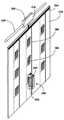
도 1은 본 발명에 따른 다수의 1차코일과 배선을 갖춘 석고보드를 부착한 방의 일부를 보여주는 사시도;
도 2는 석고보드의 부분사시도;
도 3은 도 2의 석고보드를 붙인 벽의 개략도;
도 4는 주전선에 연결할 1차코일과 배선을 갖춘 벽지의 사시도;
도 5는 이 벽지를 붙인 벽의 개략도;
도 6은 1차코일이 컨트롤박스에 연결되어 있는 벽면의 사시도;
도 7은 벽 안에 매립된 전기소자를 보여주는 개략도;
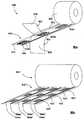
도 8은 전력콘센트 테이프 두루마리를 보여주는 사시도;
도 9는 도 8의 테이프를 붙인 벽을 보여주는 개략도;
도 10은 전력콘센트 테이프의 여러 전자소자 구성을 보여주는 개략도;
도 11은 본 발명의 다른 예에 따른 바닥밑 전력공급장치의 개략도;
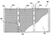
도 12는 유도전력 콘센트에서 전력을 받는 2차코일이 달린 각종 전기기기를 보여주는 도면들;
도 13은 유도전력 콘센트에서 전력을 받는 다른 전기기기를 보여주는 도면들;
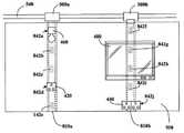
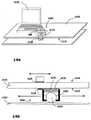
도 14는 이동기구에 전력콘센트가 설치되어 있는 경우를 보여주는 도면들;
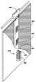
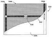
도 15는 걸레받이 뒤에 설치된 레일에서 이동기구가 움직이는 것을 보여주는 도면들;
도 16은 이동식 유도전력 콘센트의 클러치 기구를 보여주는 단면도;
도 17은 본 발명의 또다른 전력공급장치를 보여주는 개념도들;
도 18은 휴대폰 카메라로 위치빔을 전송하는 것을 보여주는 개략도와 블록도;
도 19는 본 발명의 전력누설 방지장치의 블록도;
도 20은 전력누설 방지장치에 의해 보호되는 유도전력 콘센트의 개념을 보여주는 도면들;
도 21은 원격 누설방지장치로 보호되는 다수의 유도전력 콘센트의 개략도;
도 22는 전기부하가 없을 때 전력전송을 방지하는 방법의 순서도.1 is a perspective view showing a part of a room to which a gypsum board having a plurality of primary coils and wiring according to the present invention is attached;
2 is a partial perspective view of a gypsum board;
Figure 3 is a schematic view of the wall of the gypsum board of Figure 2;
Fig. 4 is a perspective view of a wallpaper having a primary coil and wiring to be connected to the main wire; Fig.
5 is a schematic view of a wall pasted with this wallpaper;
6 is a perspective view of a wall with the primary coil connected to the control box;
7 is a schematic view showing an electric device embedded in a wall;
8 is a perspective view showing a power outlet tape roll;
Figure 9 is a schematic view showing the tape-attached wall of Figure 8;
10 is a schematic diagram showing various electronic device configurations of a power outlet tape;
11 is a schematic diagram of a bottom-bottom power supply according to another example of the present invention;
12 is a view showing various electric devices with secondary coils receiving power from an inductive power outlet;
13 is a view showing another electric appliance receiving electric power in an inductive power outlet;
14 is a view showing a case where a power outlet is installed in the moving mechanism;
FIG. 15 is a view showing the movement mechanism moving in a rail installed behind the mop; FIG.
16 is a sectional view showing a clutch mechanism of a portable induction power outlet;
17 is a conceptual diagram showing another power supply apparatus of the present invention;
18 is a schematic block diagram and block diagram illustrating transmitting a position beam to a cellular phone camera;
19 is a block diagram of the power leakage prevention device of the present invention;
20 is a view showing the concept of an inductive power outlet protected by a power leakage prevention device;
21 is a schematic view of a plurality of inductive power outlets protected by a remote leakage prevention device;
Figure 22 is a flowchart of a method for preventing power transmission in the absence of an electrical load.
도 1은 본 발명에 따른 유도전력 공급장치의 개략도이다. 방의 벽(2a,2b)과 천정(2c)과 바닥(2d)에 TV(4a), 전구(4b)와 같은 다양한 전기기기(4)가 설치되고, 이런 전기기기는 유도전력 콘센트(6)를 통해 전력을 받는다. 본 발명의 특징은, 이런 유도전력 콘센트들을 벽이나 천정이나 바닥면을 포함한 경계면(2)에 설치하는 것이다.1 is a schematic diagram of an inductive power supply according to the present invention. Various electric devices 4 such as a
전원과 전기부하 사이에 도선연결 없이도 유도결합으로 에너지를 전송할 수 있다. 전원은 1차인덕터에 유선연결되고, 발진자기장을 일으키는 1차인덕터를 통해 발진전압이 인가된다. 발진자기장은 1차인덕터 부근의 2차인덕터에 발진전류를 유도한다. 이런 식으로, 전자기 유도에 의해 1차인덕터에서 2차인덕터로 유선연결 없이도 전자기유도에 의해 전기에너지가 전송될 수 있다. 전기에너지가 전송될 때 1, 2차 인덕터 쌍이 유도결합되었다고 한다. 2차인덕터에 직렬로 유선연결된 전기부하는 인덕터들 사이에 유도결합이 있을 때 전원에서 에너지를 끌어올 수 있다.Energy can be transferred inductively without a wire connection between the power supply and the electrical load. The power source is wired to the primary inductor and the oscillating voltage is applied through the primary inductor causing the oscillating magnetic field. The oscillating magnetic field induces an oscillating current in the secondary inductor in the vicinity of the primary inductor. In this way, electromagnetic induction allows electrical energy to be transferred by electromagnetic induction without a wire connection from the primary inductor to the secondary inductor. The first and second inductor pairs are said to be inductively coupled when electrical energy is transferred. An electrical load, wired in series with the secondary inductor, can draw energy from the power supply when there is an inductive coupling between the inductors.
유도전력 콘센트(6)에서 송전선과 같은 전원에 컨트롤러를 통해 1차인덕터(7)가 유선연결된다. 컨트롤러는 1차코일을 구동하는데 필요한 전자회로를 제공한다. 이런 전자회로에는 1차인덕터에 고주파 발진전압을 제공하는 스위치가 포함된다.In the
전기기기(4)는 유도전력 콘센트(6)의 1차인덕터(7)에 유도결합된 2차인덕터(5)를 통해 전력을 받는다. 나중에 자세히 설명하겠지만, 전기기기(4)에 유선연결된 기기 안에 2차인덕터(5)를 따로 설치하거나, 전기기기 자체에 2차인덕터를 설치할 수도 있다.The electric device 4 receives electric power through the secondary inductor 5 inductively coupled to the primary inductor 7 of the
본 발명에 의하면 유도전력 콘센트를 건자재에 미리 설치할 수도 있다. 도 2와 같이, 석고보드(100)는 석고와 같은 건자재층(102) 양쪽에 주로 종이로 된 벽지(104,106)를 붙인 것이 일반적이다. 여러개의 1차인덕터(108a-f)와 연결선(110,112)을 석고보드(100)에 설치하는데, 연결선들은 석고보드의 가장자리까지 이어져 전원(도시 안됨)에 연결될 수 있다.According to the present invention, the induction power outlet can be installed in advance in the building material. As shown in Fig. 2, the
1차인덕터(108a-f)가 건자재층(102) 안에 매립될 수도 있지만, 코일 형태로 비교적 얇은 1차인덕터라면 겉면의 벽지에 간단히 부착될 수도 있다. 이런 1차인덕터는 알루미늄이나 구리로 된 전선이나 금속호일 형태로 이루어지지만, 1차인덕터(108a-f)와 연결선(110,112)이 도전잉크를 이용해 벽지(104)에 인쇄되거나 칠해질 수도 있다.The
1차코일(108)과 2차코일(602 사이의 전자기결합은 자속안내코어에 의해 개선될 수 있다. 자성체나 비정질 강자성체와 같은 자속안내코어는 1차코일과 연계되어 벽속에 매립된다. 강자성체 차폐판과 같은 다른 요소들을 추가로 설치할 수도 있다.The electromagnetic coupling between the primary coil 108 and the
도 3에서는 석고보드(100)를 벽(200)에 설치한 것으로, 석고보드 패널들(202)을 골조(204)에 설치한다. 욕실에 사용되는 석고보드(100)는 방수성을 갖는 것이 좋다. 참고로 석고보드란 일반적인 석고보드는 물론, 각종 벽판을 포함하는 개념이다.In FIG. 3, the
도 4에는 두루마리형 벽지(300)가 보인다. 이 벽지(300)는 종이나 직물로 된 유연한 시트(302)를 포함하는데, 시트의 겉면(302)에 인쇄나 무늬가 새겨진다. 시트(302)의 뒷면에 다수의 1차코일(308)이 배치된다. 1차코일은 금속호일로 이루어지거나 시트(302)에 접착된 것이거나, 실크인쇄와 같은 방법으로 시트 표면에 인쇄된 도전잉크로 이루어질 수도 있다.In FIG. 4, the scroll-shaped
도 5의 벽지(300)는 벽(400)의 표면에 부착된다. 1차코일(308)은 2차코일(602)과 유도결합된다(도 6 참조). 이런 2차코일(602)은 벽(400)의 표면(402)에 부착된 전원콘센트로 사용되는 어댑터(420)에 설치되고, 2차코일은 전등(460)이나 TV(480)와 같은 전기기기에 유선연결되거나, 테이블 위의 가구에 배치된 전기기기에 유선연결된다.
어댑터(420)는 접착제나 나사나 볼트로 벽(400)에 고정되거나, 자체와 벽면의 자석에 의해 고정될 수도 있지만, 추가 배선 없이 쉽게 교체할 수 있는 것이 바람직하다. 어댑터를 TV(480)나 음악시스템과 같은 기기 안에 직접 설치하기도 한다. TV(480)와 같은 기기는 하나의 1차코일(308)보다 간격이 넓을 수 있으므로, 1군데 이상의 여러곳에서 전원에 연결되기도 한데, 이는 필요한 전력이 한군데의 1차코일(308)에서 공급되는 전력보다 큰 경우 유용할 것이다.The
도 4의 시트(302)의 재료는 1차코일(308)이나 도전 스트립(310,312)과 같은 전기소자들을 숨기는 무늬나 조직을 갖기에 유리한 것이 좋다.The material of the
한편, 벽지(300)의 뒷면(306)은 벽(400)에 붙기 쉽게 접착면(306)을 가질 수 있다. 자가접착이나 기존의 여러가지 접착기술을 적용할 수 있다. 따라서, 저밀도 폴리에틸렌과 같은 박리층(307)을 접착면(306)에 붙여두었다가, 박리층을 벗겨 벽지(300)의 접착면(306)을 벽면에 붙일 수 있다. 한편, 앞면(301)에 박리코팅을 입혀두고, 접촉면(306)을 쉽게 드러낼 수도 있다. 물론, 다른 방식을 채탤할 수도 있다.On the other hand, the
도 6에 의하면, 컨트롤박스(500)를 회로차단기(540)에 연결하여 1차코일(508)을 구동하는데 필요한 전자회로를 벽(510)에 매립하거나 부착한다. 구동회로로는 고주파 발진전압을 일으키는 스위치와, 전력콘센트를 선택하기 위한 셀렉터가 있다. 컨트롤박스(500)는 PCB 커넥터와 같은 커넥터(520)에 의해 1차코일(508)에 연결될 수 있다. 한편, 1차코일이 전혀 없는 테이프(560)를 사용해 벽(510)과 컨트롤박스(500)를 연결하기도 한다.6, the
어댑터(600)에 2차코일(602)을 설치하고 플러그를 꽂을 수 있는 파워잭(604)에 연결할 수도 있다. 한편, 2차코일(602)이 전등(460)과 같은 전기부하에 직접 연결되기도 한다. 어댑터(600)내의 2차코일(602)이 벽(510) 안의 1차코일(508)과 정렬되면, 양쪽 코일 사이에 전력이 유도전송되어 부하에 공급된다.The
도 7의 구성에서는 기둥 안의 1차코일(708) 전체가 공통의 도전스트립(710)으로 연결된다. 제어스트립(712)을 구성하는 전선 다발의 전선마다 1차코일(708) 하나씩 연결된다. 벽이 절단되는 곳마다, 도전스트립(710)과 제어스트립(712)이 컨트롤박스(500)에 연결된다(도 5 참조). 제어스트립(712)은 따라서 1차코일을 제각기 선택적으로 작동시키는 수단이 된다. 이상 설명한 전기소자들의 구성에 의해 각각의 1차코일이 제어된다. 그러나, 당업자라면 알 수 있겠지만, 다른 구성을 채택할 수도 있다.7, the entire
석고보드를 벽에 붙이기 전에 석고보드의 이음매에 석고테이프를 붙이는데, 이렇게 하면 표면이 매끈해져 이음매에 균열이 생길 위험이 줄어든다.Before attaching the gypsum board to the wall, gypsum tape is attached to the gypsum board joints, which reduces the risk of cracks on the seams due to the smooth surface.
자가접착 석고테이프가 미국특허 5,486,394에 소개되었다. 이 테이프는 벽체 사이의 이음매를 신속히 가리는데 사용되고, 두루마리 형태로 판매된다. 이 테이프는 유연한 종이 안쪽면에 감압접착제가 발라져있는 제1 층과, 그 위에 덮여있는 강화직물로 된 제2 층과, 제1 층과 제2 층 사이의 섬유질을 둘러싸도록 직물층을 덮는 유연한 재질의 제3 층으로 이루어진다. 제3 층 바깥면에는 박리코팅이 되어 있어, 말려있는 테이프를 손으로 벗어내기 쉽도록 제1 층이 제3층과 박리가능하게 결합된다. 테이프를 벽면 모서리에 쉽게 붙일 수 있도록 테이프 중앙선을 따라 주름이 혀엉된다. 테이프의 자가박리성질 때문에 뒷면을 제거하지 않고도 테이프를 쉽게 붙일 수 있다. 벽면을 덮는 진흙층으로 테이프가 축축해져도 접착력이 유지된다. 또, 제3 층의 박리코팅 때문에 진흙벽에 화합물이나 석고등을 붙일 수 있다.A self-adhesive gypsum tape is disclosed in U.S. Patent No. 5,486,394. This tape is used to quickly cover the seams between the walls and is sold in the form of a scroll. The tape comprises a first layer with a pressure sensitive adhesive on the inside of the flexible paper, a second layer with a reinforcing fabric covered thereon, a flexible material covering the fabric layer to surround the fibers between the first and second layers As shown in FIG. The outer surface of the third layer is provided with a release coating, and the first layer is releasably coupled with the third layer so that the dried tape can be easily removed by hand. It wrinkles along the centerline of the tape to make it easier to attach the tape to the edge of the wall. Due to the self-stripping nature of the tape, the tape can be easily attached without removing the backing. The mud layer covering the wall keeps the adhesive force even if the tape becomes damp. Further, due to the peeling coating of the third layer, a compound or gypsum can be adhered to the mud wall.
도 8a에는 본 발명에 따른 유도전력 콘센트(842)를 설치한 전력콘센트 테이프(800)의 두루마리가 도시되어 있다. 이 테이프(800)는 3층으로 이루어진다. 제1 층(820)는 감압 접착면(822)을 갖고, 이 접착면이 벽면에 붙는다. 제2 층(840)은 전력콘센트 역할을 하는 1차코일(842)과 도전스트립(844,846)을 포함한 전기소자들을 갖는다. 제3 층(860)은 제2 층(840)을 덮어 전기소자들을 보호한다. 제2 층(840)의 1차코일(842)은 벽면의 콘센트로 사용되는 전력어댑터의 2차코일과 유도결합한다.8A shows a scroll of a
제3층(860)의 바깥면(862)은 저밀도 폴리에틸렌과 같은 박리제로 코팅하여, 제1층의 접착면(822)을 당기면 제3층(860)의 바깥면(862)에서 손으로 쉽게 벗겨지도록 한다. 박리제로 덮인 박리커버(도시 안됨)를 접착면(822)에 붙여 접착면에 먼지가 붙지 않도록 하고 테이프(800)가 물체에 미리 붙지 않도록 할 수도 있다.The
도 8b의 다른 전력콘센트 테이프(800')는 1차코일(842')이 2차원 배열(840')로 되어있다. 3열의 1차코일 각각에 도전스트립(844'a-c,846'a-c)이 쌍으로 있다. 이런 롤테이프(800')는 테이블, 작업대와 같이 큰 면적을 덮는데 유용하다.Another power outlet tape 800 'of FIG. 8b has a primary coil 842' in a two-dimensional array 840 '. There are pairs of conductive strips 844'a-c, 846'a-c in each of the three primary coils. Such a roll tape 800 'is useful for covering a large area such as a table or a work table.
도 9a의 테이프(800)는 벽(900)에 붙이는 것이다. 석고보드(920)를 골조(940)에 설치하고, 석고보드 사이의 이음매(960)를 없애기 위해 테이프(800)를 이음매에 붙인다. 석고보드(920) 사이의 이음매(960)를 테이프로 덮어 석고(980)를 바를 수 있는 매끈한 표면이 생긴다. 강자성체가 들어있는 석고(980)는 유도결합에 대한 추가 자속안내를 한다. 물론 종이나 천이나 마로 된 다른 테이프를 사용할 수도 있다.The
테이프의 구간 양단부에 PCB 커넥터와 같은 커넥터(520)를 사용해 컨트롤박스(500)를 연결할 수 있다. 테이프에 아무런 1차코일이 없고 테이프(800)와 컨트롤박스(500)를 연결하는 도전스트립만 있을 수도 있다.The
전선(540)에 연결된 컨트롤박스(500)는 1차코일(842)를 구동하기 위한 회로, 구체적으로는 고주파 발진전압을 공급하는 스위치나, 구동할 전력콘센트를 선택하는 셀렉터를 제공한다.The
유도전력 어댑터는 도 9b~c와 같이 벽면에 설치된 기기에 전력을 공급하는데 이용된다. 도 9b의 석고 벽(950)에는 2개의 전력콘센트 테이프(810a,b)가 숨겨져 있는데, 테이프마다 5군데의 전력공급 지점이 있고, 각 지점에 1차코일(842a-j)이 있다. 각각의 테이프(810a,b)는 전선(540)에 연결된 컨트롤박스(500a,b)에 연결된다. 벽면 기기는 다양하지만, 예를 들면 싱글 파워잭 어댑터(420), 더블 파워잭 어댑터(440), 전등 어댑터(460), 벽걸이 TV(480) 등이 있다. 이들 어댑터(420,440,460)는 접착제나 나사 등으로 벽면에 고정되는 것이 일반이지만, 자석을 이용해 고정될 수도 있고, 배선을 추가하지 않고도 전력공급 지점들 사이를 쉽게 옮겨다닐 수 있는 것이 중요하다.The inductive power adapter is used to supply power to the devices installed on the wall as shown in Figures 9b-c. There are five
어댑터를 전기기기 안에 내장할 수도 있다. 도 9b와 같이, TV(480)가 2개의 1차코일(842g,h)에 걸쳐있으면, 하나의 1차코일(842)에서 공급되는 전력보다 큰 전력을 공급받을 수 있다.The adapter may also be built into the electrical device. As shown in FIG. 9B, if the
도 9c의 유도전력 어댑터(600)는 컨트롤박스(500)에 연결된 전력콘센트 테이프(810)를 따라 전력공급 지점(842)에 결합된다. 어댑터(600)의 2차코일(602)은 파워잭(604)에 유선연결되고, 파워잭은 기존의 파워플러그에 결합된다. 한편, 2차코일(602)이 전기부하에 직접 유선연결될 수도 있다. 2차코일(602)이 테이프(800)의 1차코일(842)과 정렬될 때 양쪽 코일 사이에 전력의 전송이 일어난다.The
도 10a에서는 공통의 도전스트립(844)이 테이프를 따라 모든 1차코일(842)과 연결되도록 전기소자(840)를 배치한다. 제어스트립(846)을 이루는 도전선 각각은 1차코일(842)에 하나씩 연결된다.In Figure 10a, the
전력콘센트 테이프를 두루마리 뭉치에서 손으로 일정 길이씩 찢거나 가위나 칼을 사용해 잘라낸다. 테이프를 잘라낸 뒤, 공통의 도전스트립(844)과 제어스트립(846)이 컨트롤박스(500)에 연결된다. 제어스트립(846)은 1차코일(842)을 선택적으로 작동시키는데 이용되기도 한다.Tear off the power outlet tape by hand lengthwise from the roll of rolls or cut with scissors or a knife. After cutting off the tape, a common
도 10b의 테이프의 전기소자(640)에서는 각각의 1차코일(642)에 자체의 전용 도전스트립(644,646)에 연결된다. 1차코일(642) 각각의 도전스트립은 테이프를 따라 뻗어있어, 충분한 길이로 테이프를 절단할 수 있다. 예컨대 A 라인을 따라 테이프를 자르면, 도전스트립(644b-d,646b-d)에 대한 접점이 생겨, 3개의 1차코일(642b~d) 각각을 제어할 수 있다. C 라인에서 테이프를 절단하면, 도전스트립(644d-f,646d-f)에 접점이 생겨, 다음 3개의 1차코일(642d~f) 각각을 제어한다. 여기서는 테이프에서 3개의 1차코일만 개별적으로 통제할 수 있는 것으로 설명했지만, 도전스트립(644,646)의 길이에 따라 개별적으로 통제할 수 있는 1차코일의 수도 바뀔 수 있다. 즉, 테이프의 길이가 도체의 연장길이를 변화시키고, 이는 통제가능한 1차코일의 수도 변화시킨다.In the
Reichelt의 미국특허 6,444,962에서 소개한 히터기는 평평한 형태의 히터로 이루어지고, 이런 히터는 2개의 도체가 평행하게 배치되고, 그 사이에 전자기파를 일으키는 코팅물질이 배치되며, 코팅물질은 결합제, 절연제, 분산제, 물 및 흑연으로 이루어진다. 이 히터기에 달린 컨트롤러가 갖춘 고조파 발생기의 전기소자는 급속한 전류상승을 일으키고 고조파를 일으킨다. 고조파 발생기는 히터의 도체에 결합되어 자연 분자주파수 범위의 진동스펙트럼을 방출한다. 따라서, 벽지와 비슷하게 평판 형태의 저렴하고 고효율인 히터기가 제공된다. 이런 평평한 벽걸이 히터는 기존의 벽지 안에 설치될 수 있다.The heater disclosed in Reichelt's U.S. Patent 6,444,962 is made up of a heater of a flat shape, in which two conductors are arranged in parallel, with a coating material disposed therebetween causing electromagnetic waves, the coating material comprising a binder, Dispersant, water and graphite. The electric elements of the harmonic generators equipped with the controller in this heater cause rapid current rise and harmonics. The harmonic generator is coupled to the conductor of the heater to emit a vibration spectrum in the natural molecular frequency range. Thus, an inexpensive, high-efficiency heater is provided in a plate-like form similar to a wallpaper. These flat wall-mounted heaters can be installed in existing wallpaper.
도 1로 돌아가면, 유도코일이나 내부저항이 높은 강자성체 실드가 있어서, 전류를 유도하는 외에도, 전류가 진동을 하여 발열효과를 더 낸다는 놀라운 장점이 밝혀졌다. 이런 가열효과는 방(1) 안을 가열하는 히터에 이용되고, 저항이 높은 유도코일을 바닥(2d)이나 창문 밑에 배치하면, 실내의 대류효과를 더 높일 수 있다.Returning to Fig. 1, there is an incredible advantage that an induction coil or a ferromagnetic shield having a high internal resistance, besides inducing a current, oscillates the current to exert a heat generating effect. This heating effect is used for the heater that heats the inside of the chamber 1, and the convection effect of the room can be further enhanced by disposing the induction coil having a high resistance under the
사무실이나 공장이나 전시장이나 창고와 같은 지역에서는 벽면에서 떨어진 곳에서 전기기기에 전력을 공급해야할 경우가 많다. 귀찮은 전선을 피하기 위해 바닥이나 천정에 설치된 소켓에서 전력을 공급받을 수 있지만, 둘다 문제가 있다. 종래의 바닥설치 플러그와 케이블은 발에 채여 연결부에 손상을 주거나 주변 사람에게 상처를 주기도 했으며, 많은 경우 소켓과 전선 주변을 깨끗하게 유지해야만 한다. 천정 설비는 천정에서 케이블이 늘어져 보기가 좋지 않으며 대형 홀이나 극장과 같이 천정이 높은 곳이나 천정이 없는 야외에서는 쓸모가 없다.In areas such as offices, factories, exhibition halls, and warehouses, electrical equipment is often required to be powered off the wall. You can get power from a socket installed on the floor or ceiling to avoid annoying wires, but both are problematic. Conventional floor-mounted plugs and cables have been found to damage the connections or hurt people around the feet, and in many cases must be kept clean around the sockets and wires. Ceiling equipment is not good at hanging cables in the ceiling, and is useless in high ceilings such as large halls and theaters, or outdoors without ceilings.
도 11에는 위의 문제의 해결책이 제시되었는데, 여기서는 바닥에 설치된 유도전력 콘센트(1200)이 하부 배선(1220)을 통해 전원(도시 안됨)에 직접 연결되거나 컨트롤러를 통해 전원에 연결된다. 1차코일(1200)은 상부의 2차코일(1300)과 유도결합되고, 2차코일 자체는 전기부하(1320,1325)에 유선연결된다. 이런 식으로, 개방된 바닥 소켓들을 피할 수 있다. 이 장치(1100)는 러그, 카펫, 마루, 리놀륨, 타일 등이 깔린 모든 바닥에 사용될 수 있다.A solution to the above problem is presented in Fig. 11, wherein an
스탠드(1320a)나복사기(1320b)와 같이 바닥에 2차코일(1300)이 있는 바닥설치 기기(1320)는 바닥면 1차코일(1200) 바로 위에 위치한다. 책상(1325a)이나 의자(1325b)와 같이 2차코일(1300)을 갖춘 가구(1325)는 1차코일(1200) 위에 위치하면, 그 위에 배치된 독서등(1340a)이나 랩탑컴퓨터(1340b)나 물을 가열하는 커피머그(1340c)와 같은 전기기기(1340)에 전력을 공급하는 플랫폼 역할을 한다.The floor installation device 1320 having the
이런 전기기기(1340)는 소켓에 플러그를 끼우는 방식으로 가구(1325)에 유선연결되거나, 자체 내장된 2차코일(1500)이 가구 윗면(1326)의 1차코일(1400)에 유도결합한다.The electric device 1340 is connected to the furniture 1325 by plugging the socket into the socket or induction-coupled to the
시스템(1100)의 1차코일(1200)과 정렬하는 2차코일(1200)을 갖춘 다른 전기기기로는 스탠드, TV, 오디오장치, 비디오장치, DVD, 식기세척기, 건조기는 물론, 오븐, 쿠커, 냉장고, 냉동고 등도 포함된다. 작업대에서 시스템(1100)은 세절기, 선풍기, 복사기, 컴퓨터, 프린터와 같은 장치에 전력을 공급할 수 있다.Other electrical appliances having a
가구(1325)에 1차코일(1400)을 설치하고 작업대의 기기와 연결된 2차코일(1500)과 1차코일이 유도결합을 할 수도 있다. 이런 1차코일이 설치된 가구로는 의자, 식탁, 작업대, 파티션, 식기장 등이 있다.The
작업대 윗면(1326)에 설치된 1차코일(1400)과 정렬되는 2차코일(1500)을 내장한 기기로는 탁상등, 조명기기, 선풍기, 무선전화기, 스피커, 스피커폰, 회의용 전화기, 전자펜, 전자 스테이플러, 디스플레이 기기, VDU, 프로젝터, TV, 비디오, 오디오장치, 컴퓨터, 계산기, 스캐너, 프린터, 팩스머신, 복사기, 세절기, 가열판, 전기가열 머그, 휴대폰 등이 있다.A speaker, a speakerphone, a speakerphone, a conference phone, an electronic pen, an electronic pen, and the like, which incorporate a secondary coil 1500 that is aligned with the
욕실에서 사용되는 개인위생을 위한 전기기기도 많은데, 예를 들면, 면도기, 칫솔, 헤어드라이어, 헤어컬러 등이 있으며, 욕실에서 사용되는 다른 전기기기로는 히터와 전등이 있다. 그러나, 물과 전기는 절대로 분리되어야 하는 것이다. 욕실에서의 감전은 아주 위험하며, 전등스위치는 대부분 욕실 바깥에 위치한다. 이런 문제는 1회용 건전지나 충전식 배터리로 작동되는 전기기기로 해결할 수 있다. 그러나, 1회용 건전지는 고가이고 환경파괴를 한다.There are many electrical appliances for personal hygiene in the bathroom, such as a razor, a toothbrush, a hair dryer, hair color, etc. Other electrical appliances used in the bathroom include a heater and a light bulb. However, water and electricity should never be separated. Electric shocks in bathrooms are very dangerous, and most light switches are located outside the bathroom. This problem can be solved by using a disposable battery or an electric appliance powered by a rechargeable battery. However, disposable batteries are expensive and cause environmental destruction.
욕실의 벽면은 세라믹 타일로 덮이고 세면기와 그 주변은 천연이나 인조 대리석, 스테인리스 스틸, 세라믹, 아크릴 등으로 만들어 청소하기 쉽게 만드는 것이 일반적이다. 안전을 위해, 욕실내 전기소켓은 보통 방수커버로 덮인다. 전력콘센트 소켓은 플러그를 꽂는 구멍이 있어서 작업면보다 청소하기가 쉽지 않으며, 스위치는 단락이나 마모나 감전방지를 위해 항상 건조상태를 유지해야 한다.The walls of the bathroom are covered with ceramic tiles, and the wash basin and its surroundings are made of natural or artificial marble, stainless steel, ceramics, acrylic, etc. to make it easy to clean. For safety reasons, the electric socket in the bathroom is usually covered with a waterproof cover. The power receptacle socket has a plug hole, which makes it easier to clean than the work surface, and the switch should always be dry to prevent shorts, wear and shocks.
유도결합으로 전기기기에 전력을 공급하면, 욕실내의 감전의 위험이 최소화되어 욕실에서 전기기기를 사용할 수 있다.Powering electrical equipment with inductive coupling minimizes the risk of electric shocks in the bathroom and allows electrical equipment to be used in the bathroom.
도 12a의 오디오기기와 같은 전기기기(2010)는 콘센트의 소켓에 플러그를 꽂는 방식이 아니라, 바닥(2014)에 2차코일(2012)을 내장한 것이다. 이 전기기기(2010)는 세면대 주변의 표면(2016)에 배치되어 전력을 공급받는데, 표면에는 1차코일(2018)이 설치되고, 2차코일(2012)이 1차코일(2018)과 정렬된다. 1차코일(2018)은 드라이버(2017)를 통해 전원(2019)에 유선연결되고, 드라이버는 1차코일을 구동하는데 필요한 전자회로를 제공한다. 전자회로에는 고주파 발진전압을 공급하는 스위치가 있다.The
오디오기기 외에도, 헤어드라이어, 면도기, 히터, 헤어컬러, 수염다듬이, TV, 라디오, 체중기와 같은 다른 전기기기도 사용할 수 있다. 세면기나 벽면 타일과 같은 욕실내 표면층(2015 뒤에 1차코일을 숨길 수도 있다. 1차코일은 욕실장의 문이나 벽안에 숨길 수도 있다. 마찬가지로, 러그, 카펫, 리놀륨, 타일 등의 바닥면 뒤에 1차코일을 숨기고, 전선으로 연결하지 않고도 전기기기를 작동시킬 수 있다. 심지어는 1차코일이 세라믹이나 아크릴로 된 세면기나 욕조 안에 내장될 수도 있다.In addition to audio equipment, other electrical equipment such as hair dryers, razors, heaters, hair colors, beard trimmings, TVs, radios and weightlifters can be used. A surface layer in the bathroom, such as a wash basin or wall tile, can hide the primary coil behind the 2015. The primary coil can also be hidden behind the door or wall of the bathroom. Likewise, the bottom of the rug, carpet, linoleum, You can hide the coils and operate the electrical appliances without connecting them to the wires. Even the primary coils can be built into ceramic or acrylic washbasins or bathtubs.
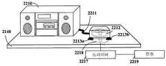
도 12b의 전기기기(2210)의 2차코일(2212)는 전선(2211)을 통해 연결되고, 진공흡착기(2213)을 이용해 2차코일(2212)이 표면(2026)에 부착되며, 그 밑에 1차코일(2218)이 위치한다. 1차코일(2218)은 드라이버(2217)를 통해 전원(2219)에 연결된다. 욕실 표면은 청소가 쉽도록 매끄러운 것이 좋다. 이런 특징 때문에 경량 물체를 욕실 표면(2216)에 임시로 붙이는데 흡착기(2213)를 이용할 수 있다. 흡착기(2213)를 2차코일(2212) 부근에 배치하여, 1차코일(2218) 위에 2차코일(2212)을 부착한다.The
도 12c에서는 샤워기의 물줄기가 어쩌다 전구(2310)를 향하고 있고, 전구에 불이 들어왔으면 이때 감전이 일어날 수 있으므로, 욕실내 전구는 완전히 밀폐되어야 한다. 본 발명에서는 전구(2310)가 유전체(2304)에 의해 전원(2302)에서 완전히 절연되어 있고, 2차코일(2312)을 갖추고 있다. 1차코일(2318)은 방수 석고보드(2320) 안에 설치된다. 이렇게 하여 욕실내 안전대책이 마련된다.In FIG. 12C, if the water stream of the shower head is sometimes pointed at the
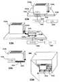
도 12d에 도시된 욕실장(2405)의 서랍(2400) 안에 1차코일(2418)이 설치된다. 심지어는 서랍 바닥(2404)을 대형의 직사각형 1차코일(2418)로 덮고, 1차코일을 전원에 연결할 수도 있다. 전동칫솔(2424), 헤어드라이어(2426), 면도기(2428)과 같은 충전식 전기기기에 2차코일을 설치하고 이들을 서랍(2400) 안에 두기만해도 충전이 이루어질 수 있다.A
도 12e에서는 전용 스탠드(2500)에 1차코일(2518)이 설치되고, 이를 이용해 전기기기를 충전할 수 있다. 예를 들면, 스탠드를 칫솔홀더로 사용하여 2차코일(2512)을 내장한 전동칫솔(2524)를 충전할 수 있다.In Fig. 12E, the
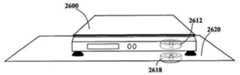
도 12f에서는 욕실용 체중계(2600)에 2차코일(2612)을 설치하고, 바닥(2620)에 내장된 1차코일(2618) 위에 놓는다.In Fig. 12F, the
이와 같이, 본 발명에 의하면 욕실의 청소를 어렵게 하고 감전의 위험을 초래하는 기존의 전력콘센트 소켓을 없앨 수 있다.As described above, according to the present invention, it is possible to eliminate the existing power outlet socket which makes it difficult to clean the bathroom and creates a risk of electric shock.
냉장고, 냉동고, 스토브, 식기세척기와 같은 기기는 전력이 많이 필요한 대형장치로서, 소켓에 플러그를 끼워야 하는 것이고 움직이기가 힘들며, 하부 부분을 청소하기도 힘들다. 이런 기기는 보통 도전에 의해 전력을 공급받는다.Devices such as refrigerators, freezers, stoves, and dishwashers are large, heavy-duty devices that require plugs in the sockets, are difficult to move, and are difficult to clean. These devices are usually powered by challenge.
에그비터, 제빵기, 믹서, 주서, 녹즙기, 음식물처리기, 전동칼, 토스터, 살균기, 팝콘메이커, 자석교반기, 와플메이커, 전기 바베큐그릴, 슬로우쿠커, 가열판, 튀김기, 프라이팬, 칼갈이, 전동식 깡통따개 등등의 주방기기는 사용하지 않을 때 식기장에 보관된다. 이런 기기는 개수대나 조리대나 식탁을 포함한 모든 작업면에서 사용할 수 있어야 한다. 기존의 주방에서는 이런 작업면 위에 2구짜리 소켓을 설치하고, 이곳에 플러그를 꽂아 주방기기를 사용하곤 했다.Electric cooker, electric cooker, electric cooker, electric cooker, electric stirrer, popcorn maker, magnetic stirrer, waffle maker, electric barbecue grill, slow cooker, hot plate, fryer, frying pan, calgary, electric can opener Kitchen appliances are kept in a cupboard when not in use. Such appliances shall be available for all workplaces, including sinks, cookers, and dining tables. In conventional kitchens, I used a two-socket socket on this work surface and a kitchen appliance by plugging it in here.
음식을 조리하는 주방은 청결을 유지해야 한다. 벽면에는 타일을 붙이고 조리대는 연마석이나 스테인리스 스틸이나 포미카를 깔아 청소하기 쉽게 하는 것이 보통이다. 기존의 전원소켓은 구멍이 있어서 이런 작업면보다 청소하기가 어렵고, 단락이나 마모나 감전방지를 위해 스위치는 항상 건조상태를 유지해야 한다.Kitchens that cook food should be kept clean. It is common to put tiles on the wall, and the countertops are made of grindstone, stainless steel, or foamed to make it easier to clean. Conventional power sockets have holes that make it harder to clean than these work surfaces, and the switch should always be dry to avoid shorts, wear and shock.
주기적으로 물을 채워야 하는 주전자는 안전을 위해 전원과의 연결을 끊어야만 하고, 제대로 설계된 주방이라면 소켓이 싱크대 가까이 있지 않고 주전자의 전선은 보통 짧다. 플러그 달린 전선이 싱크대에 닿으면 위험하므로, 이를 피하기 위해 주전자의 전선은 보통 접속점에서 연결을 끊는다. 그러나 이런 접속점이 물에 젖으면, 단락이 일어나 퓨즈가 끊어질 위험이 있어 불편을 초래하며, 심지어는 감전이 될 위험도 있다.A kettle that needs to be periodically filled with water must be disconnected from the power source for safety, and if it is a well-designed kitchen, the socket is not near the sink and the kettle's wires are usually short. To prevent this, the kettle's wires usually disconnect from the connection point, since it is dangerous if the plug-in wires touch the sink. However, if these junctions get wet, there is a risk of short-circuiting the fuse and causing inconvenience, or even an electric shock.
경우에 따라서는 1회용이나 충전식 배터리를 사용해 이 문제를 풀 수 있지만, 1회용 배터리는 비싸고 환경에도 유해하다. 또, 이런 배터리는 특히 고전력이 요구되는 전기주전자나 튀김기에 사용할 때는 작동 도중에 전력이 완전히 소비될 위험도 있다.In some cases, disposable or rechargeable batteries can solve this problem, but disposable batteries are expensive and harmful to the environment. In addition, such a battery may be completely consumed during operation, especially when used in an electric kettle or fryer requiring high power.
도 13a의 전기기기(3120)는 토스터로서, 종래와 같이 소켓에 플러그를 꽂지 않고, 기기 바닥(3122)에 2차코일(3124)를 설치한다. 1차코일(3144)을 설치한 작업면(3140) 위에 전기기기(3120)를 놓으면 2차코일(3124)과 1차코일(3144)이 정렬된다. 여기서는 토스터를 예로 들었지만, 에그비터, 제빵기 등등의 전술한 어떤 기기도 이용할 수 있다.The electric device 3120 shown in Fig. 13A is a toaster, and a
1차코일(3144)은 드라이버(3180)를 통해 전원(3160)에 유선연결되고, 드라이버는 1차코일을 구동하는데 필요한 전자회로를 제공한다. 전자회로에는 고주파 발진전압을 공급하는 스위치가 있다.
1차코일(3144)를 주방조리대의 표면층(3142) 밑에 숨길 수도 있다. 표면층은 플라스틱, 비닐, 포미카, 베니어판 등으로 이루어진다. 마찬가지로, 러그나, 카펫이나, 리놀륨이나 바닥타일 등의 밑에 1차코일을 숨기고 바닥 위에 가전기기를 배치할 수도 있다.The
인조대리석, Corian®이나 Caesar®과 같은 빌딩 표면재로서의 폴리머 매트릭스 복합체인 수지 안에 1차코일을 설치할 수도 있다. Caesar 스톤은 세면대나 개수대로 만들 수 있다. 1차코일을 표면 밑에 설치하려면 뒷쪽에서 구멍을 뚫어야 하는 자연석과는 달리, Caesar 스톤과 같은 복합재는 유도코일이나 연결선과 같은 금속물체 둘레에 주조할 수 있다.Primary coils can also be installed in resin, which is a polymer matrix composite as a building facade, such as artificial marble, Corian® or Caesar®. Caesar stone can be made in a sink or sink. Unlike natural stones, which require drilling a hole in the back to install the primary coil under the surface, composites such as Caesar stones can be cast around metal objects such as induction coils or connecting wires.
도 13b의 전기기기(3120)는 2차코일(3124)가 전선(3126)에 연결되어 있는 토스터이고, 진공흡착기(3128)를 이용해 2차코일(3124)이 1차코일(3144) 위의 작업면(3140)에 부착된다. 도 13a와 마찬가지로, 1차코일(3144)은 조리대와 같은 작업면(3140) 안에 설치된다. 1차코일이 건물의 벽면이나 벽장 안에 설치될 수도 있다.13B is a toaster in which the
주방의 표면은 청소하기 쉽도록 매끄러운 것이 좋다. 이 경우 흡착기를 사용해 전등을 주방 표면에 일시적으로 부착할 수 있다. 2차코일을 1차코일 위에 부착하는데 사용되는 흡착기(3129)는 여러개일 수도 있다.The surface of the kitchen should be smooth and easy to clean. In this case, the lamp can be temporarily attached to the kitchen surface using an adsorber. There may be several adsorbers 3129 used to attach the secondary coil onto the primary coil.
도 13a~b의 기기에서 종래와 마찬가지로 소켓과 플러그를 이용해 유선으로 전원에 연결하는 것도 물론 가능하다.It is of course possible to connect the power source to the power source by using a socket and a plug in the apparatus of Figs.
도 13c의 신축코드(3123)은 기기(3120c)의 베이스(3122) 안에 감길 수 있다. 도 13a~b의 기기(3120a,b)에도 적용될 수 있는 축전기(3125)를 이용해, 유도결합이나 도전 전력공급을 이용할 수 없는 경우 기기를 충전할 수도 있다. 이 경우, 본 발명의 기기를 휴대형으로 만들어 어떤 작업면에서도 사용할 수 있을 것이다.The
자동차에 많이 사용되는 납축전지는 높은 전류를 생성하는 것이고, 충전식 배터리는 휴대폰이나 랩탑컴퓨터와 같은 전자기기에 장기간 전력을 공급하기 위한 것이다. 본 발명은 수십초에서 2~3시간 동안 전동기를 작동시키는 전력을 공급하기 위한 커패시터나 전기화학 축전기를 포함한 기기에 관한 것으로서, 음식처리기, 토스터, 전기주전자 등에 사용할 수 있다.Lead-acid batteries, which are widely used in automobiles, generate high currents, and rechargeable batteries are intended to provide long-term power to electronic devices such as mobile phones or laptop computers. The present invention relates to a device including a capacitor or an electrochemical capacitor for supplying electric power for operating a motor for several tens of seconds to two or three hours, and can be used in a food processor, a toaster, an electric kettle, and the like.
도 13d의 보관소(3000)는 바닥에 1차코일(3121)이 설치된 서랍이나 식기장 같은 것으로, 도 13c의 축전기(3125)가 달린 기기를 저장했다가 꺼내서 사용하기 위한 것이다. 이곳에서는 축전기(3125)를 필요할 때 완전히 충전할 수 있다.The
이상 설명한 장치에서, 전력 콘센트는 대개 일정한 장소에 고정되어 있지만, 경우에 따라서는 움직일 수도 있다. 도 14a에 도시된 본 발명에 따른 이동식 전력콘센트(4100)는 컴퓨터(4182)와 같은 기기에 전력을 공급하기 위한 것이다. 표면층(4140)의 뒷면(4142) 가까이 있는 1차코일(4120)은 이동기구(4160)에 고정되고 컴퓨터(4182)에 유선연결된 2차코일(4180)과 유도결합된다. 이동기구(4160)는 표면층(4140) 뒤에서 1차코일(4120)을 움직이기 위한 것이다.In the apparatus described above, the power outlet is usually fixed at a certain place, but it may be moved in some cases. The
1차코일(4120)은 1차코일을 구동하는데 필요한 전자회로, 예컨대 고주파 발진전압을 공급하는 스위치를 제공하는 컨트롤러(도시 안됨)를 통해 전원에 유선연결된다. 콘센트(4100)를 벽면이나 벽장에 설치할 수도 있다. 이 경우, 1차코일(4120)은 벽지나 벽판의 표면층(4140) 뒤에서 움직일 것이다. 콘센트(4100)를 책상이나 조리대나 회의용 탁자나 작업대와 같은 수평 플랫폼의 표면층 뒤에 설치할 수도 있다. 또, 1차코일(4120)이 러그나 카펫이나 리놀륨이나 바닥타일과 같은 바닥면 밑에서 움직이게 할 수도 있다.The
도 14b에 의하면, 표면층(4120)과 바닥층(4162) 사이에 배치된 1차코일(4120)이 롤러(4163)가 달린 운반대(4161)에 고정되어 바닥층(4162) 위를 움직인다. 철이나 강철이나 영구자석과 같은 자석(4166)이 운반대(4161)에 부착되어, 표면층(4140)의 윗면(4144)에 배치된 자석(4168)에 의해 당겨진다. 자석(4168)이 움직이면 자석(4166)을 당겨, 1차코일(4120)도 움직이므로, 필요한 곳에 1차코일을 배치할 수 있다.14B, a
롤러(4163) 대신에 바퀴나 스키나 부양 자석을 사용할 수도 있다. Teflon과 같은 저마찰재를 표면에 바르면 이동기구(4160)가 움직이는데 도움이 된다.Instead of the
도 15a의 다른 이동기구(5160)에서는 1차코일(5120)이 레일(5162)에 미끄럼 가능하게 설치된다. 레일(5162)은 벽(5140)의 걸레받이(5141) 뒤에 수평으로 위치하고, 1차코일(5120)은 레일(5162)을 따라 움직인다. 전술한 것처럼, 1차코일을 자석을 이용해 수동으로 당기거나, 전동 바퀴(5164)를 달아 레일(5162)에서 자체적으로 움직이도록 할 수도 있다.In the other moving mechanism 5160 of Fig. 15A, the
레일(5162)은 곡선일 수도 있는데, 심지어는 도 15b와 같이 벽(5140)의 표면 전체에 걸쳐 뱀처럼 앞뒤로 구불구불하게 배치될 수도 있다. 다수의 1차코일(5120b)이 서로 독립적으로 움직이거나 같이 움직이도록 배치할 수도 있다.The
도 15c에서는, 1차코일(5120)이 설치된 이동기구(5160c)이레일(5162)에서 미끄러지는데, 이 레일은 한쌍의 지지궤도(5164)를 가로질러 수직으로 배치되어 지지궤도를 타고 움직일 수 있다. 레일과 지지궤도가 H-프레임(5165)을 형성한다. 따라서, 1차코일(5120)이 표면층(5140) 뒤에서 움직일 수 있다.In Fig. 15C, a moving
벽과 같은 수직 표면층(5140) 뒤에서 이동기구(5160)가 수직으로 위치할 경우, 지지궤도(5164)를 풀리로 교체할 수도 있다. 이런 풀리는 레일(5163)을 지지하면서 수동으로나 자동으로 레일을 승강시킨다. 한편, 벽의 폭을 가로질러 고정된 갠트리빔을 따라 수평으로 움직이는 크롤리에 설치된 풀리에 1차코일(5120)이 달려있을 수도 있다.When the moving mechanism 5160 is vertically positioned behind a vertical surface layer 5140 such as a wall, the support trajectory 5164 may be replaced with a pulley. These pulleys lift the rails manually or automatically while supporting the rail 5163. On the other hand, there may be a
또, 도 15d와 같이 4개의 안내케이블(5162a-d)에 1차코일(5120)을 고정한 운반기구(5160)도 있다. 안내케이블의 길이는 풀리(5164a-d)에 의해 독립적으로 제어되며, 풀리는 사각형(5166)의 4 모서리에 위치한다. 1차코일(5120)은 풀리(5164)에 의해 사각형(5166) 어느 곳에도 위치할 수 있다. 1차코일(5120)을 조작하는데 3개 이상의 풀리를 사용할 수도 있고, 또는 2개나 한개의 풀리만을 사용해 1차코일을 직선으로 움직일 수도 있다.There is also a carrying mechanism 5160 in which the
도 16a의 다른 실시예에서는, 1차코일(6120)이 표면층(6140)의 뒷면(6142) 가까이 위치하고 표면층의 앞면(6142) 위에 있는 2차코일(6180)과 유도결합한다. 2차코일(6180)은 전등(6184)과 같은 전기기구에 유선연결된다.16A, a
1차코일(6120)과 2차코일(6180) 사이의 유도결합을 최대화하려면, 간격을 최소화해야 한다. 따라서, 1차코일(6120)을 표면층(6140)의 뒷면(6142)에 타이트하게 압착하는 것이 좋고, 이를 위해 압축스프링(6122)으로 1차코일(6120)을 뒷면(6142)에 밀어준다. 한편, 뒷면(6142)에 홈(6146)을 파고, 이곳에 1차코일을 설치하면 1차코일과 2차코일 사이의 간격을 더 줄일 수 있다. 강자성체로 이루어진 자속안내코어(6124)를 1차코일(6120)과 표면층(6140) 내부의 2차코일(6180)에도 설치하면, 유도결합을 더 좋게할 수 있다.In order to maximize the inductive coupling between the
그러나, 뒷면(6142)에 1차코일(6120)을 누르면 마찰이 커져 1차코일의 움직임을 방해할 수 있다. 이때문에, 뒷면(6142)에서 1차코일(6120)을 분리하는 분리기(6130)를 이용할 수 있다. 본 발명에서는, 운반대(6126)에 고정된 지점(P)을 중심으로 피봇하는 레버(6132)의 한쪽 단부에 1차코일(6120)을 부착하고, 레버의 타단부에는 표면층(6140)의 뒷면(6142) 가까이로 영구자석(6134)을 부착한다.However, when the
도 16b의 분리기(6130)에서는, 표면층(6140)의 앞면(6144)에 있는 두번째 자석(6136)이 첫번째 자석(6134) 가까이 배치된다. 첫번째 자석(6134)이 두번째 자석(6136)에 의해 뒷면(6142)쪽으로 당겨지면, 레버(6132)가 움직이면서 스프링(6122)을 누르고 1차코일(6120)이 뒷면(6142)에서 떨어진다. 운반대(6126)는 자유롭게 1차코일(6120)을 새 위치로 옮길 수 있다. 이들 자석(6134,6136)이 도 14b와 같은 이동기구(6160)를 제공하기도 한다.In the
자동화를 위해, 분리기(6130)에서 표면층(6140) 뒷쪽의 운반대(6126)에 전자석을 설치할 수 있다. 이 전자석은 뒷면(6142)에서 1차코일(6120)을 분리하여 전술한 자석(6134,6136)의 기능을 하는데 사용된다.For automation, an electromagnet may be installed on the
이상 설명한 유도전력 콘센트는 플러그 핀을 꽂을 구멍이 필요 없어서, 기존의 콘센트보다 효과적이고 방해물도 되지 않는다. 소켓이 없는 콘센트는 방해물이 되지 않는다는 점에서 장점이지만, 기존의 것에 비해 찾기가 어렵다는 점이 단점이고 새로이 해결해야할 문제점이다. 사용자는 사용하기 전에 감춰진 콘센트가 어디있는지 찾아야 한다.The above-described inductive power outlet does not need a hole for plug pin insertion, so it is more effective than conventional outlet and does not become an obstacle. Socketless receptacles are an advantage in that they do not become an obstacle, but they are difficult to find compared to existing ones and are a new problem to solve. The user must find out where the outlet is hidden before use.
이런 콘센트를 찾는 문제는 책상이나 벽면 안에 가려져있거나 이동기구에 설치되었을 때 특히 문제가 된다. 전력콘센트를 궤도나 아암에 설치하고, 이들을 가린 표면에 위치를 표시하면 이런 문제를 해결할 수 있다.The problem of finding such an outlet is particularly problematic when it is hidden in a desk or wall, or installed in a moving appliance. This problem can be solved by installing a power outlet on a track or an arm and marking the position on the shielded surface.
도 17a는 본 발명에 따라 위치를 찾을 수 있는 전력 콘센트(7100)를 보여주는데, 이 콘센트(7100)에서 벽면이나 작업면과 같은 표면(7140)에 디스플레이(7110)를 설치하여, 표면(7140)에 가려진 1차코일(7120)의 위치를 나타낸다.Figure 17a shows a
1차코일(7120)은 1차코일을 구동하는데 필요한 전자회로, 예컨대 고주파 발진전압을 공급하는 스위치를 제공하는 컨트롤러(도시 안됨)를 통해 전원에 유선연결된다. 이런 1차코일(7120)은 벽면이나 벽장 안에 가려지거나, 벽지의 표면(7140)에 가려지거나, 책상이나 조리대나 작업대와 같은 수평면 뒤에 가려지거나, 러그나 카펫이나 리놀륨이나 바닥타일 밑에 가려질 수 있다.The
도 17b와 같이, 1차코일(7120)의 위치가 알려지면, 2차코일(7180)을 1차코일에 정렬시킬 수 있다. 이렇게 정렬된 1차코일(7120)은 2차코일과 유도결합하여, 컴퓨터(7182)와 같이 2차코일에 유선연결된 전기기기에 전력을 공급할 수 있다.As shown in FIG. 17B, when the position of the
일례로, 숨겨진 1차코일(7120)의 위치가 표면(7140)에 설치된 디스플레이(7110)에 의해 사용자에게 알려진다. 1차코일(7120)의 위치(7114)가 표시된 표면(7140)의 지도(7112)가 디스플레이(7110)에 나타난다.In one example, the position of the hidden
도 17c에서는, 본 발명의 콘센트(7101)의 1차코일(7121)이 H-프레임(7161)에 설치되어, 벽 뒤에 가려져있다. 1차코일(7121)은 제어반(7111)에서 원격으로 조정할 수 있고, 제어반에 나타난 지도(7123)상의 마커(7125)의 위치가 1차코일(7121)의 위치이다.In Fig. 17C, the
제어반(7111)은 터치스크린일 수 있는데, 이 경우 마커(7125)는 커서로서 움직일 것이다. 마커(7125)는 1차코일(7121)의 위치를 나타내면서 위치를 조정할 수도 있다. 한편, 제어반(7111)이 이동식 기계적 스위치일 수도 있는데, 이 경우 스위치의 위치가 1차코일(7121)의 위치를 표시한다. H-프레임(7161)을 예로들어 설명했지만, 다른 이동기구를 이용할 수도 있다.The
도 18a의 다른 전력콘센트(8100)의 숨겨진 1차코일(8120)은 송신기로서 LED(8110)를 달고있어, 1차코일의 위치를 표시하는 위치빔(L)을 LED에서 낸다. 표면(8140)은 LED에서 나오는 파장을 투과시키므로, 위치빔(L)은 이 파장에 반응하는 광다이오드에 의해 검출된다. 0.8mm 두께의 포미카 시트 뒷쪽의 LED에서 나온 적외선은 현대의 많은 휴대폰(8200)에 설치된 디지탈카메라에 의해 감지될 수 있다.The hidden
플라스틱, 카드보드, 포미카, 종이와 같은 많은 재료로 된 박막(8140)은 적외선을 투과한다. LED(8110)에서 나오는 전자기 스펙트럼의 적외선 영역의 빛은 인간의 눈에는 안보이지만, 디지탈카메라에는 쉽게 감지되고, 이런 적외선 LED를 1차코일(8120)에 설치하면, 카메라가 달린 휴대폰으로 1차코일(8120)의 위치를 쉽게 찾을 수 있다. 그러나, 박막(8140)의 두께와 LED의 파장을 투과하는 재질을 선택한다면 육안으로도 빛을 감지할 수 있도록 할 수 있을 것이다.A
자외선, 마이크로파, 무선파는 물론 X선이나 더 짧은 파장의 전자기파도 감지할 수 있는 디텍터를 선택할 수 있으므로, 이 문제에 대한 해결책은 아주 많다고 할 수 있다. 또, 다른 종류의 방사선이나 가청범위나 이를 벗어난 초음파와 같은 기계적 진동을 포함한 다른 종류의 신호를 보내는 송신기를 사용해 1차코일을 찾는 것도 가능하다.There are many solutions to this problem as you can choose ultraviolet, microwave, radio waves, as well as detectors that can detect X-rays or shorter wavelength electromagnetic waves. It is also possible to find a primary coil using a transmitter that sends a different kind of signal, including other types of radiation, mechanical vibration, such as audible range or ultrasound off it.
도 18b는 다른 전력콘센트(8101)의 블록도이다. 1차코일(8121)은 자체 위치를 식별하는 암화 위치신호(S)를 띠는 위치빔(L)을 송신한다. 이동식 1차코일(8121)은 스위치(8114)와 마이크로컨트롤러(8116)를 통해 전원(8112)에 연결된다. 스위치(8114)는 비트율 주파수(f)로 전원(8112)을 1차코일(8121)에 단속적으로 연결한다. 위치확인 모니터(8118)는 1차코일(8121)의 위치를 모니터하고 위치신호(S)를 마이크로컨트롤러(8116)에 보낸다. 마이크로컨트롤러(8116)는 이 위치신호(S)를 변조한다. 1차코일(8121)에 걸린 전압은 위치신호(S)를 띤 주파수 f의 변조된 가변전압이고, 이 전압은 주파수 f의 무선파를 내며, 이 무선파가 위치빔(L)으로 전송될 수 있다. 한편, 위치빔(L)이 1차코일(8121)과는 별도의 전용 송신기에서 전송될 수도 있다.Fig. 18B is a block diagram of another
수신기(8221)가 달린 수신장치(8201)를 이용할 수 있다. 수신기(8221)는 주파수 f의 위치빔(L)을 받으며, 수신된 위치빔(L)은 주파수 f의 기준신호와 상관되어 위치신호(S)를 분리한다. 1차코일(8121)의 위치가 이렇게 원격 수신장치(8201)로 전송되어, 1차코일의 위치를 디스플레이에 출력하게 된다.A
이상 디지탈 비트율 변조 위치빔(L)에 대해 설명했지만, 이런 위치빔(L)은 아날로그/디지탈 주파수변조나 진폭변조와 같은 다른 방식으로 변조될 수도 있다.Although a digital bit rate modulation position beam L has been described above, this position beam L may be modulated in other ways such as analog / digital frequency modulation or amplitude modulation.
위치확인 모니터(8118)는 몇몇 기준점에서 1차코일(8121)의 움직임을 추적하여 1차코일의 움직임을 직접적으로 감시할 수도 있다. 적외선 근접센서, 초음파 센서, 자기 센서(예; 홀센서), 유도센서, 용량센서 등의 다른 외부센서를 이용해 삼각측량법으로 1차코일(8121)의 움직임을 간접적으로 감시할 수도 있다.Positioning
하이파워 유도전력 콘센트가 작동되면 큰 자기장을 일으킨다. 2차인덕터가 1차인덕터에 유도결합되는 곳에 생긴 자속결합에 의해 2차인덕터에 전력이 공급된다. 전력을 받을 2차인덕터가 없으면, 발진 자기장에 의해 고에너지 전자기파가 전송되는데, 이 전자기파는 주변 사람들에게 유해하다. 또, 저전력 장치에서는 과잉 열이 쉽게 분산되지만, 결합되지 않은 고전력 1차코일이나 그 주변은 고온으로 위험해진다.A high-power inductive power outlet causes a large magnetic field when it is turned on. Power is supplied to the secondary inductor by magnetic flux coupling where the secondary inductor is inductively coupled to the primary inductor. Without a secondary inductor to receive power, high-energy electromagnetic waves are transmitted by the oscillating magnetic field, which is harmful to people around. In a low-power device, excessive heat is easily dispersed, but a high-power primary coil and its periphery that are not combined are dangerous at high temperatures.
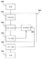
도 19는 온/오프 스위칭되는 유도전력 콘센트(9200)의 전력누설 방지시스템(900)의 블록도로서, 2차코일(9260)이 1차코일(9220)에서 에너지를 받을 수 있는 곳에서만 1차코일이 교류자기장을 일으킨다.19 is a block diagram of a power
유도전력 콘센트(9200)의 1차코일(9220)은 전원(9240)에 유선연결되고, 전기부하(9264)에 유선연결된 2차코일(9260)과 유도결합한다. 본 발명의 이 실시예의 중요 특징은, 회로차단기(9280)가 전원과 1차코일(9220) 사이에 직렬 연결되어, 작동되었을 때 전원과 1차코일의 연결을 끊는데 있다.The
1차코일(9220)은 드라이버(9230)를 통해 전원(9240)에 유선연결되고, 드라이버는 고주파 발진전압을 제공하는 스위치와 같은 회로를 제공한다. 콘센트(9200)의 1차코일(9220)이 다수이면, 드라이버(9230)는 어느 1차코일을 작동시킬지 선택하는 셀렉터를 구비할 수 있다.The
회로차단기(9280)가 드라이버(9230)와 1차코일(9220) 사이에 배치되면, 회로차단기는 1차코일(9220)의 연결만을 끊는다. 한편, 회로차단기가 전원(9240)과 드라이버(9230) 사이에 연결될 경우에는 1차코일(9220)과 함께 드라이버(9230) 자체의 연결을 끊을 수 있다.If a
회로차단기(9280)는 컨트롤러(9400)의 제어를 받고, 컨트롤러는 1차코일(9220)이 전력을 전송함을 나타내는 1차신호(P)와, 2차코일(9260)이 1차코일(9220)에 유도결합되어 전력을 받음을 나타내는 2차신호(S)를 받는다. 컨트롤러(9400)가 1차신(P)만 받고 2차신호(S)를 받지 않았을 때는 회로차단기(9280)를 작동시켜 1차코일(9220)과 전원(9240)의 연결을 끊는다.The
도 20은 유도전력 콘센트(9201)를 국부 누설방지시스템(9001)로 보호하는 것을 보여주는 개략도이다. 도 20a의 1차코일(9221)은 책상, 조리대, 회의테이블, 작업대와 같은 수평 플랫폼(9641)의 표면층 뒤에 숨겨져 있다. 이런 플랫폼은 운모, 포미카, 베니어판과 같은 다양한 재료로 만들어질 수 있다. 한편, 전술한바와 마찬가지로, 1차코일(9221)이 바닥면 밑이나, 벽면이나 벽장 뒤에 숨겨질 수도 있다.20 is a schematic diagram showing that the
1차코일(9221)은 2차코일(9261)에 연결된 컴퓨터(9262)와 같은 전기기기에 전력을 공급하는데 사용되는데; 컴퓨터(9262)는 플랫폼(9641) 위에 있고, 컴퓨터(9262)에 결합된 2차코일(9261)이 플랫폼 안에 숨겨진 1차코일(9221)과 정렬된다.The
본 발명에서, 1차디텍터(9421)이 1차코일(9221) 부근에 위치하면서 1차코일(9221)에서 생긴 자기장을 감지한다. 디텍터(9421)는 자기센서이거나 열센서, 전자기센서일 수 있다.In the present invention, the primary detector 9421 is located near the
2차코일(9261)의 존재나 동작을 감지하는 2차디텍터(9441)를 설치할 수도 있다. 2차디텍터(9441)는 2차코일(9261)의 신호나 1차코일의 신호를 감지하거나 1차코일과 유도결합된 2차코일의 존재를 직간접적으로 표시하는 신호를 감지하기도 한다. 2차디텍터는 1차코일(9221) 주변에서 플랫폼의 온도상승을 감지하는 열센서이거나, 자기센서, 홀센서, 전자기센서일 수 있다.A secondary detector 9441 for detecting the presence or operation of the
도 20a의 구성에서, 2차코일(9261)이 1차코일(9221)에 유도결합되면, 2kczh일(9261)이 1차코일(9221)로부터 전력을 받아, 전기기기(9262)가 작동된다. 그 결과, 1차디텍터(9421)은 1차코일에서 생긴 자기장을 감지하여, 전력이 전송되고 있음을 나타내는 1차신호(P)를 컨트롤러(9401)에 보낸다. 전기기기에 전력이 전송되고 있기 때문에, 온도를 감지하는 2차디텍터(9441)는 아무런 온도상승을 감지하지 못하고, 전기부하가 1차코일에 유도결합되었음을 나타내는 2차신호(S)를 컨트롤러(9401)에 보내거나, 컨트롤러(9401)의 논리프로그램에 따라 같은 표시를 하기도 한다.20A, when the
컨트롤러(9401)가 1차코일(9221)에 전력이 있음을 나타내는 1차신호(P)와, 전기부하가 존재함을 나타내는 2차신호(S)를받으면, 회로차단기(9281)는 작동하지 않은채 1차코일(9221)이 계속해서 전원(9241)으로부터 전력을 인출한다.When the controller 9401 receives a primary signal P indicating that power is present in the
2차코일(9261)이 1차코일(9221)에 유도결합되지 않으면(도 20b 참조), 1차코일(9221)에서 전송된 전력이 플랫폼(9641)에서 열로 분산된다. 이 경우 1차디텍터(9421)가 1차코일(9221)에서 생긴 자기장을 감지하고, 전력이 1차코일에 의해 전송되고 있음을 나타내는 1차신호(P)를 컨트롤러(9401)에 보낸다. 그러나, 2차디텍터(9441)는 플랫폼에 생긴 열로 인한 온도상승을 감지하여, 전기부하가 1차코일에 유도결합되지 않았음을 나타내는 2차신호(S)를 보낸다. 컨트롤러(9401)는 전력이 발생되고 있음을 나타내는 1차신호(P)와, 전기부하가 없음을 나타내는 2차신호(S)를 받아, 회로차단기(9281)를 작동시키므로, 1차코일과 전원의 연결이 끊어지고 1차코일에서의 전력전송이 차단된다.When the
도 21에서는 다수의 유도전력 콘센트(9203)가 원격 누설방지시스템(9003)의 보호를 받는다. 1차코일(9223)은 벽(9643) 안에 설치되고 드라이버(9233)를 통해 전원에 연결되며, 부근의 전등과 같은 전기기기에 유선연결된 2차코일(9263)과 유도결합하도록 배치된다.In FIG. 21, a plurality of inductive power receptacles 9203 are protected by the remote
1차코일(9223)이 작동되면, 드라이버(9233)가 특성주파수 f로진동하는 가변전압을 공급하고, 1차코일은 f의 무선파를 송신한다. 원격 누설방지시스템(9003)은 벽(9643) 안에 무선수신기(9423)과 같은 1차디텍터를 구비하는데, 1차디텍터는 특성주파수 f의 무선파를 감지하고, 이런 무선파는 적어도 하나의 1차코일(9223)이 전력을 전송함을 나타낸다.When the
2차디텍터(9443)는 1차코일(9223)에 유도결합된 2차코일(9263)을 감지한다. 2차코일이 1차코일에 유도결합되었음을 나타내는 2차신호에 의해 전력전송이 변조된다.The
1차디텍터(9423)는 2차신호를 확인하기 위해 무선파를 복조한다. 2차신호가 감지되지 않으면, 1차디텍터(9423)는 2차코일이 없는 상태에서 1차코일이 전력을 전송중임을 나타내는 제어신호(C)를 컨트롤러(9500)에 보낸다. 이 경우, 컨트롤러는 회로차단기를 작동시켜 모든 1차코일(9223)의 연결을 끊는다.The
한편, 드라이버(9233)는 무선파를 전송하는 가동 1차코일(9223a-h)을 식별하는 1차신호로 각각의 가동 1차코일의 전력전송을 일으키는 변조기(도시 안됨)를 갖출 수도 있다. 이때, 1차디텍터(9423)는 1차신호를 감지하여, 2차코일이 없는 상태에서 전력을 전송하는 1차코일을 확인한다. 1차디텍터(9423)는 이를 컨트롤러(9500)에 보내 해당 1차코일만의 연결을 끊는다.On the other hand, the driver 9233 may have a modulator (not shown) that causes power transmission of each movable primary coil to a primary signal that identifies the movable
본 발명의 유도전력 콘센트가 전기부하 없이는 전력전송을 하지 않는 방법에 대해 도 22를 참조하여 설명한다. 이 방법의 단계는 아래와 같다:A method in which the inductive power outlet of the present invention does not transmit power without an electric load will be described with reference to Fig. The steps of this method are as follows:
a) 1차코일이 전력전송;a) the primary coil transfers power;
b) 1차코일의 전력전송 감지;b) power transmission detection of the primary coil;
c) 2차코일이 1차코일에 유도결합된 2차코일 조사; 및c) secondary coil irradiation inductively coupled to the primary coil by the secondary coil; And
d) 2차코일이 감지되지 않을 경우 1차코일과 전원의 연결 끊음.
d) If the secondary coil is not detected, the primary coil is disconnected from the power supply.
Claims (21)
Translated fromKorean상기 유도전력 콘센트는 넓은 표면의 뒷면에 위치한 1차인덕터를 구비하고, 발진전압을 공급받기 위해 구동회로를 통해 전원에 연결될 수 있으며;
상기 1차인덕터는 유도전력 수신기와 유도결합하고;
상기 유도전력 수신기는 2차인덕터를 구비하며;
1차인덕터를 움직이고, 사용자가 제어할 수 있으며, 모터로 작동되는 이동기구가 상기 넓은 표면 뒤에 위치하는 것을 특징으로 하는 유도전력 공급장치.An inductive power supply for transmitting power from an inductive power outlet to an inductive power receiver, comprising:
The inductive power receptacle having a primary inductor located on a back surface of a large surface and being connectable to a power source via a drive circuit for receiving an oscillating voltage;
Said primary inductor being inductively coupled to an inductive power receiver;
The inductive power receiver having a secondary inductor;
Wherein the primary inductor is movable, user-controllable, and a motorized motion mechanism is located behind the large surface.
a. 상기 1차인덕터에 의해 전송된 전력을 감지하기 위한 1차디텍터;
b. 상기 1차인덕터에 2차인덕터가 유도결합된 것을 검출하기 위한 2차디텍터; 및
c. 상기 1차디텍터와 2차디텍터 둘다와 연결되어 회로차단기를 작동시키는 컨트롤러;를 더 포함하는 것을 특징으로 하는유도전력 공급장치.8. The method of claim 7,
a. A primary detector for sensing power transmitted by the primary inductor;
b. A secondary detector for detecting that the secondary inductor is inductively coupled to the primary inductor; And
c. Further comprising: a controller coupled to both the primary detector and the secondary detector to operate the circuit breaker.
Applications Claiming Priority (19)
| Application Number | Priority Date | Filing Date | Title |
|---|---|---|---|
| US96063607P | 2007-10-09 | 2007-10-09 | |
| US60/960,636 | 2007-10-09 | ||
| US110607P | 2007-10-31 | 2007-10-31 | |
| US60/001,106 | 2007-10-31 | ||
| US99646007P | 2007-11-19 | 2007-11-19 | |
| US60/996,460 | 2007-11-19 | ||
| US99659207P | 2007-11-27 | 2007-11-27 | |
| US60/996,592 | 2007-11-27 | ||
| US99692207P | 2007-12-11 | 2007-12-11 | |
| US60/996,922 | 2007-12-11 | ||
| US603707P | 2007-12-17 | 2007-12-17 | |
| US61/006,037 | 2007-12-17 | ||
| US831907P | 2007-12-20 | 2007-12-20 | |
| US61/008,319 | 2007-12-20 | ||
| US613207P | 2007-12-26 | 2007-12-26 | |
| US61/006,132 | 2007-12-26 | ||
| US623808P | 2008-01-02 | 2008-01-02 | |
| US61/006,238 | 2008-01-02 | ||
| PCT/IL2008/001347WO2009047768A2 (en) | 2007-10-09 | 2008-10-12 | Inductive power providing system |
Related Parent Applications (1)
| Application Number | Title | Priority Date | Filing Date |
|---|---|---|---|
| KR1020107010220ADivisionKR20100087712A (en) | 2007-10-09 | 2008-10-12 | Inductive power providing system |
Publications (2)
| Publication Number | Publication Date |
|---|---|
| KR20100082008A KR20100082008A (en) | 2010-07-15 |
| KR101524892B1true KR101524892B1 (en) | 2015-06-01 |
Family
ID=40549694
Family Applications (2)
| Application Number | Title | Priority Date | Filing Date |
|---|---|---|---|
| KR1020107010227AActiveKR101524892B1 (en) | 2007-10-09 | 2008-10-12 | Inductive power providing system having moving outlets |
| KR1020107010220ACeasedKR20100087712A (en) | 2007-10-09 | 2008-10-12 | Inductive power providing system |
Family Applications After (1)
| Application Number | Title | Priority Date | Filing Date |
|---|---|---|---|
| KR1020107010220ACeasedKR20100087712A (en) | 2007-10-09 | 2008-10-12 | Inductive power providing system |
Country Status (8)
| Country | Link |
|---|---|
| EP (1) | EP2206129A4 (en) |
| JP (2) | JP2011501633A (en) |
| KR (2) | KR101524892B1 (en) |
| CN (1) | CN102017031A (en) |
| AU (2) | AU2008309154A1 (en) |
| CA (1) | CA2702164A1 (en) |
| MX (1) | MX2010003837A (en) |
| WO (1) | WO2009047768A2 (en) |
Cited By (1)
| Publication number | Priority date | Publication date | Assignee | Title |
|---|---|---|---|---|
| KR20180011133A (en)* | 2015-05-22 | 2018-01-31 | 레이-지-보이 인코포레이티드 | Apparatus and method for wireless power transmission in furniture articles |
Families Citing this family (93)
| Publication number | Priority date | Publication date | Assignee | Title |
|---|---|---|---|---|
| CN101802942A (en) | 2007-01-29 | 2010-08-11 | 普迈公司 | Pinless power coupling |
| EP3975372B1 (en) | 2007-03-22 | 2024-01-31 | Powermat Technologies Ltd. | Efficiency monitor for inductive power transmission |
| KR20100061845A (en) | 2007-09-25 | 2010-06-09 | 파우워매트 엘티디. | Adjustable inductive power transmission platform |
| US10068701B2 (en) | 2007-09-25 | 2018-09-04 | Powermat Technologies Ltd. | Adjustable inductive power transmission platform |
| US8193769B2 (en) | 2007-10-18 | 2012-06-05 | Powermat Technologies, Ltd | Inductively chargeable audio devices |
| US20100219183A1 (en) | 2007-11-19 | 2010-09-02 | Powermat Ltd. | System for inductive power provision within a bounding surface |
| US8536737B2 (en) | 2007-11-19 | 2013-09-17 | Powermat Technologies, Ltd. | System for inductive power provision in wet environments |
| JP5662532B2 (en)* | 2007-12-18 | 2015-01-28 | パナソニック株式会社 | Charging stand |
| US8884468B2 (en) | 2007-12-21 | 2014-11-11 | Access Business Group International Llc | Circuitry for inductive power transfer |
| JP2009159683A (en)* | 2007-12-25 | 2009-07-16 | Panasonic Electric Works Co Ltd | Building with contactless power supply function and contactless power supply outlet |
| JP2009159675A (en)* | 2007-12-25 | 2009-07-16 | Panasonic Electric Works Co Ltd | Non-contact power supply panel |
| US8228026B2 (en) | 2008-02-25 | 2012-07-24 | L & P Property Management Company | Inductively coupled shelving and storage containers |
| US8421407B2 (en) | 2008-02-25 | 2013-04-16 | L & P Property Management Company | Inductively coupled work surfaces |
| CN102084442B (en) | 2008-03-17 | 2013-12-04 | 鲍尔马特技术有限公司 | Inductive transmission system |
| US9337902B2 (en) | 2008-03-17 | 2016-05-10 | Powermat Technologies Ltd. | System and method for providing wireless power transfer functionality to an electrical device |
| US9960640B2 (en) | 2008-03-17 | 2018-05-01 | Powermat Technologies Ltd. | System and method for regulating inductive power transmission |
| US9960642B2 (en) | 2008-03-17 | 2018-05-01 | Powermat Technologies Ltd. | Embedded interface for wireless power transfer to electrical devices |
| US9331750B2 (en) | 2008-03-17 | 2016-05-03 | Powermat Technologies Ltd. | Wireless power receiver and host control interface thereof |
| US8320143B2 (en) | 2008-04-15 | 2012-11-27 | Powermat Technologies, Ltd. | Bridge synchronous rectifier |
| US20090284369A1 (en) | 2008-05-13 | 2009-11-19 | Qualcomm Incorporated | Transmit power control for a wireless charging system |
| US8242880B2 (en) | 2008-05-29 | 2012-08-14 | Georgia Tech Research Corporation | Tongue operated magnetic sensor systems and methods |
| AU2009254785A1 (en) | 2008-06-02 | 2009-12-10 | Powermat Technologies Ltd. | Appliance mounted power outlets |
| US8188619B2 (en) | 2008-07-02 | 2012-05-29 | Powermat Technologies Ltd | Non resonant inductive power transmission system and method |
| US8981598B2 (en) | 2008-07-02 | 2015-03-17 | Powermat Technologies Ltd. | Energy efficient inductive power transmission system and method |
| US11979201B2 (en) | 2008-07-02 | 2024-05-07 | Powermat Technologies Ltd. | System and method for coded communication signals regulating inductive power transmissions |
| WO2010004560A1 (en) | 2008-07-08 | 2010-01-14 | Powermat Ltd. | Display device |
| EP2342797A2 (en) | 2008-09-23 | 2011-07-13 | Powermat Ltd | Combined antenna and inductive power receiver |
| RU2011132944A (en) | 2009-01-06 | 2013-02-20 | Эксесс Бизнесс Груп Интернешнл Ллс | INDUCTIVE POWER SUPPLY |
| US9312924B2 (en)* | 2009-02-10 | 2016-04-12 | Qualcomm Incorporated | Systems and methods relating to multi-dimensional wireless charging |
| US20100201312A1 (en) | 2009-02-10 | 2010-08-12 | Qualcomm Incorporated | Wireless power transfer for portable enclosures |
| AU2010234396A1 (en) | 2009-04-08 | 2011-10-27 | Access Business Group International Llc | Selectable coil array |
| JP5642944B2 (en)* | 2009-05-29 | 2014-12-17 | パナソニック株式会社 | Power supply device |
| JP5891419B2 (en)* | 2009-06-02 | 2016-03-23 | パナソニックIpマネジメント株式会社 | Power supply device |
| JP5496553B2 (en)* | 2009-06-15 | 2014-05-21 | 三洋電機株式会社 | Charging stand |
| US8482160B2 (en)* | 2009-09-16 | 2013-07-09 | L & P Property Management Company | Inductively coupled power module and circuit |
| EP2502244A4 (en) | 2009-11-16 | 2013-07-10 | 300K Entpr Pty Ltd | Contactless coupling and method for use with an electrical appliance |
| JP4669560B1 (en)* | 2009-12-11 | 2011-04-13 | エンパイア テクノロジー ディベロップメント エルエルシー | Contactless information management / charging system, mobile communication terminal and contactless information / power transmission unit |
| JP2011147513A (en)* | 2010-01-19 | 2011-08-04 | Panasonic Electric Works Co Ltd | Furniture with non-contact power supplying function |
| JP5537168B2 (en)* | 2010-01-19 | 2014-07-02 | パナソニック株式会社 | Planar structure with contactless power supply function |
| JP2011151900A (en)* | 2010-01-19 | 2011-08-04 | Panasonic Electric Works Co Ltd | Contactless power supply system |
| JP5478326B2 (en) | 2010-03-30 | 2014-04-23 | パナソニック株式会社 | Contactless power supply system |
| WO2011163544A2 (en)* | 2010-06-24 | 2011-12-29 | Johnson Controls Technology Company | Surface integrated circuit for power transmission and method of manufacture |
| CN102959823B (en)* | 2010-07-02 | 2015-08-19 | 皇家飞利浦电子股份有限公司 | Induction type electric power supply system |
| FR2962696B1 (en)* | 2010-07-16 | 2016-07-01 | Renault Sa | NON-CONTACT CHARGE OF A MOTOR VEHICLE BATTERY. |
| DE102011050342A1 (en)* | 2011-05-13 | 2012-11-15 | Dr. Hahn Gmbh & Co. Kg | Method and device for contactless transmission of electrical energy between a wall and a wing attached to this wall |
| EP2633598A2 (en)* | 2010-10-28 | 2013-09-04 | Koninklijke Philips Electronics N.V. | Wireless electrical power supply unit and arrangement comprising a light transmissive cover and lighting system |
| GB201019767D0 (en) | 2010-11-22 | 2011-01-05 | Bpb Ltd | Actuator and method of manufacture thereof |
| US9502907B2 (en) | 2010-12-10 | 2016-11-22 | Hayward Industries, Inc. | Power supplies for pool and spa equipment |
| CN103518310B (en)* | 2010-12-21 | 2017-05-03 | 海尔集团公司 | Wireless power supply wall |
| JP5654367B2 (en) | 2011-01-28 | 2015-01-14 | パナソニックIpマネジメント株式会社 | Power supply module of non-contact power supply device, method of using power supply module of non-contact power supply device, and method of manufacturing power supply module of non-contact power supply device |
| JP5847161B2 (en)* | 2011-03-31 | 2016-01-20 | 積水化学工業株式会社 | Building and its construction method |
| JP2013009466A (en)* | 2011-06-22 | 2013-01-10 | Sekisui Chem Co Ltd | Magnetic field resonance type non-contact power supply device |
| KR101234982B1 (en)* | 2011-07-12 | 2013-02-20 | 김완중 | Printed circuit board manufacturing dc application without power line and communications line and, direct current(dc) power supply device of dc application device capable of wire-communicating having the same |
| KR101238043B1 (en)* | 2011-09-02 | 2013-02-27 | 한창수 | Mike system |
| JP5906456B2 (en)* | 2011-09-15 | 2016-04-20 | パナソニックIpマネジメント株式会社 | Contactless power supply system and repeater |
| CN103032798B (en)* | 2011-09-29 | 2016-09-28 | 上海美迪馨电子科技有限公司 | A kind of LED desk lamp |
| DE102011118564A1 (en)* | 2011-11-15 | 2013-05-16 | Grossenbacher System Ag | Contactless power supply and signal transmission through cladding element for building parts |
| JP2013118734A (en)* | 2011-12-01 | 2013-06-13 | Panasonic Corp | Non-contact electric power transmission apparatus |
| TW201328104A (en)* | 2011-12-22 | 2013-07-01 | Primax Electronics Ltd | Wireless charger |
| JP2013139697A (en)* | 2012-01-05 | 2013-07-18 | Atelier Tekuto:Kk | Electrically conductive interior finishing material and power supply device |
| JP2013243792A (en)* | 2012-05-17 | 2013-12-05 | Sharp Corp | Charging device |
| JP5229414B1 (en)* | 2012-05-17 | 2013-07-03 | パナソニック株式会社 | Portable terminal charger and car using it |
| JP5948676B2 (en)* | 2012-05-18 | 2016-07-06 | パナソニックIpマネジメント株式会社 | Non-contact power supply system, non-contact power supply device, and power supplied device |
| US9490649B2 (en) | 2012-06-13 | 2016-11-08 | Toyota Motor Engineering & Manufacturing North America, Inc. | System and method for wireless charging |
| JP5999328B2 (en)* | 2012-07-12 | 2016-09-28 | パナソニックIpマネジメント株式会社 | Contactless power supply system for lighting |
| JP5914879B2 (en)* | 2012-10-31 | 2016-05-11 | パナソニックIpマネジメント株式会社 | Non-contact power supply system, movable device, and control method for power supply device of non-contact power supply system |
| WO2014147736A1 (en)* | 2013-03-19 | 2014-09-25 | パイオニア株式会社 | Power transmission device |
| JP6119390B2 (en)* | 2013-04-11 | 2017-04-26 | 株式会社Ihi | Appliance and contactless power supply system |
| CN206004326U (en)* | 2013-07-31 | 2017-03-08 | 奇姿设计(私人)有限公司 | Display module |
| JP2015035935A (en)* | 2013-08-09 | 2015-02-19 | 積水化学工業株式会社 | Power supply system, power supply method and architecture member |
| JP6219104B2 (en)* | 2013-09-19 | 2017-10-25 | トヨタホーム株式会社 | Building wall structure |
| CN103984265A (en)* | 2014-05-19 | 2014-08-13 | 苏州乐聚一堂电子科技有限公司 | Wireless two-way controller |
| WO2015196296A1 (en)* | 2014-06-25 | 2015-12-30 | Elix Wireless Charging Systems Inc. | Methods and apparatus for automatic alignment of wireless power transfer systems |
| DE102014116767A1 (en)* | 2014-11-17 | 2016-05-19 | Schneider Electric Industries Sas | Electrical installation device |
| ZA201509303B (en)* | 2014-12-22 | 2022-12-21 | Schneider Electric Australia Pty Ltd | Switch assembly, system and method |
| EP3091528B1 (en)* | 2015-05-05 | 2020-10-07 | Harman Professional Denmark ApS | Support frame for video wall |
| NL2016241B1 (en)* | 2016-02-09 | 2017-08-15 | Trespa Int Bv | A decorative panel |
| KR102132894B1 (en)* | 2016-10-18 | 2020-07-10 | (주)엘지하우시스 | Artificial marble having wireless charging function for mobile phone |
| EP3382844A1 (en)* | 2017-03-31 | 2018-10-03 | Koninklijke Philips N.V. | Wirelessly supplied tool processing container |
| KR102481864B1 (en) | 2018-01-29 | 2022-12-28 | 삼성전자주식회사 | Electronic apparatus and method for controlling thereof |
| JP7100845B2 (en)* | 2018-05-18 | 2022-07-14 | 株式会社レーザーシステム | Power transmission device and power transmission method |
| CA3104486A1 (en) | 2018-06-20 | 2019-12-26 | Hayward Industries, Inc. | Power supplies for pool and spa equipment |
| SG11202101477WA (en)* | 2018-08-21 | 2021-03-30 | Mitsubishi Electric Corp | Non-contact power supply system, power reception apparatus for non-contact power supply, and activation signal transmission method by power reception apparatus for non-contact power supply |
| JP7213538B2 (en)* | 2019-03-05 | 2023-01-27 | 国立大学法人 東京大学 | wireless power transfer sheet |
| WO2020247916A1 (en) | 2019-06-07 | 2020-12-10 | Jonathan Nord | Docking station with spatially-adjusted wireless energy transfer and digital offloading |
| CN110336365A (en)* | 2019-07-18 | 2019-10-15 | 深圳全景空间工业有限公司 | A wireless power supply wall |
| IT201900016508A1 (en)* | 2019-09-17 | 2021-03-17 | Luce 5 S R L | ELECTROMAGNETIC INDUCTION SYSTEM FOR IGNITION OF A LUMINOUS ELEMENT |
| DE102019129185A1 (en)* | 2019-10-29 | 2021-04-29 | Hamberger Industriewerke Gmbh | Wall, floor, ceiling panel and covering |
| DE102020100075A1 (en)* | 2020-01-03 | 2021-07-08 | PUK Group GmbH & Co. KG | Supply device, energy supply system and method for electrical energy supply |
| US12241912B2 (en) | 2021-10-22 | 2025-03-04 | Raytheon Company | Socketless or flush mount QFN (quad flat no lead) test board, fixture, and method |
| JP2023074489A (en)* | 2021-11-17 | 2023-05-29 | 忠北大学校産学協力団 | COIL ALIGNMENT CONTROL METHOD AND APPARATUS FOR MOBILE WIRELESS CHARGING |
| WO2023218131A1 (en)* | 2022-05-13 | 2023-11-16 | T. Morimoto Oy | Building board system |
| EP4312347A1 (en)* | 2022-07-27 | 2024-01-31 | Smart Electric Works Co.,Ltd. | Magnetic traction moveable wireless power supply system |
Citations (4)
| Publication number | Priority date | Publication date | Assignee | Title |
|---|---|---|---|---|
| JPH09215211A (en)* | 1996-02-02 | 1997-08-15 | Sumitomo Wiring Syst Ltd | Electric vehicle charging system |
| US20070182367A1 (en)* | 2006-01-31 | 2007-08-09 | Afshin Partovi | Inductive power source and charging system |
| JP2008109762A (en)* | 2006-10-24 | 2008-05-08 | Olympus Imaging Corp | Power transmission device |
| JP2009081946A (en)* | 2007-09-26 | 2009-04-16 | Seiko Epson Corp | Structure |
Family Cites Families (14)
| Publication number | Priority date | Publication date | Assignee | Title |
|---|---|---|---|---|
| JPH04156242A (en)* | 1990-10-17 | 1992-05-28 | Sekisui Chem Co Ltd | Wireless power supply system |
| US5221877A (en)* | 1992-03-10 | 1993-06-22 | Davis Controls Corporation | Power reduction control for inductive lighting installation |
| WO1995011544A1 (en)* | 1993-10-21 | 1995-04-27 | Auckland Uniservices Limited | A flux concentrator for an inductive power transfer system |
| CN2175481Y (en)* | 1993-11-13 | 1994-08-24 | 孙文耀 | Transformer with loss-free function |
| US5530435A (en)* | 1993-12-09 | 1996-06-25 | Steelcase Inc. | Utility distribution system for modular furniture and the like |
| JPH0736556U (en)* | 1993-12-13 | 1995-07-04 | 株式会社ユー・アール・ディー | Connectionless power transfer device |
| US5486394A (en)* | 1994-08-26 | 1996-01-23 | E-Z Taping System, Inc. | Self-release self-adhesive drywall tape |
| JP3624453B2 (en)* | 1995-03-24 | 2005-03-02 | 松下電工株式会社 | Distribution board |
| US6870475B2 (en)* | 2002-07-08 | 2005-03-22 | Draeger Medical Systems Inc. | Electrically isolated power and data coupling system suitable for portable and other equipment |
| JP2005110412A (en)* | 2003-09-30 | 2005-04-21 | Sharp Corp | Power supply system |
| JP2006102055A (en)* | 2004-10-04 | 2006-04-20 | Cleanup Corp | Cordless power supply |
| US7262700B2 (en)* | 2005-03-10 | 2007-08-28 | Microsoft Corporation | Inductive powering surface for powering portable devices |
| US20080116847A1 (en)* | 2006-09-01 | 2008-05-22 | Bio Aim Technologies Holding Ltd. | Systems and methods for wireless power transfer |
| EP2082468A2 (en)* | 2006-10-26 | 2009-07-29 | Koninklijke Philips Electronics N.V. | Floor covering and inductive power system |
- 2008
- 2008-10-12KRKR1020107010227Apatent/KR101524892B1/enactiveActive
- 2008-10-12EPEP08837639.7Apatent/EP2206129A4/ennot_activeWithdrawn
- 2008-10-12CNCN2008801197749Apatent/CN102017031A/enactivePending
- 2008-10-12MXMX2010003837Apatent/MX2010003837A/enactiveIP Right Grant
- 2008-10-12KRKR1020107010220Apatent/KR20100087712A/ennot_activeCeased
- 2008-10-12WOPCT/IL2008/001347patent/WO2009047768A2/enactiveApplication Filing
- 2008-10-12JPJP2010528526Apatent/JP2011501633A/enactivePending
- 2008-10-12AUAU2008309154Apatent/AU2008309154A1/ennot_activeAbandoned
- 2008-10-12CACA2702164Apatent/CA2702164A1/ennot_activeAbandoned
- 2010
- 2010-05-19AUAU2010202026Apatent/AU2010202026A1/ennot_activeAbandoned
- 2010-08-03JPJP2010174809Apatent/JP5660434B2/enactiveActive
Patent Citations (4)
| Publication number | Priority date | Publication date | Assignee | Title |
|---|---|---|---|---|
| JPH09215211A (en)* | 1996-02-02 | 1997-08-15 | Sumitomo Wiring Syst Ltd | Electric vehicle charging system |
| US20070182367A1 (en)* | 2006-01-31 | 2007-08-09 | Afshin Partovi | Inductive power source and charging system |
| JP2008109762A (en)* | 2006-10-24 | 2008-05-08 | Olympus Imaging Corp | Power transmission device |
| JP2009081946A (en)* | 2007-09-26 | 2009-04-16 | Seiko Epson Corp | Structure |
Cited By (2)
| Publication number | Priority date | Publication date | Assignee | Title |
|---|---|---|---|---|
| KR20180011133A (en)* | 2015-05-22 | 2018-01-31 | 레이-지-보이 인코포레이티드 | Apparatus and method for wireless power transmission in furniture articles |
| KR102092209B1 (en) | 2015-05-22 | 2020-03-24 | 레이-지-보이 인코포레이티드 | Apparatus and method for wireless power transmission in household articles |
Also Published As
| Publication number | Publication date |
|---|---|
| MX2010003837A (en) | 2011-08-26 |
| CN102017031A (en) | 2011-04-13 |
| AU2010202026A1 (en) | 2010-06-10 |
| WO2009047768A2 (en) | 2009-04-16 |
| JP5660434B2 (en) | 2015-01-28 |
| KR20100082008A (en) | 2010-07-15 |
| JP2011030418A (en) | 2011-02-10 |
| CA2702164A1 (en) | 2009-04-16 |
| EP2206129A4 (en) | 2016-03-09 |
| AU2008309154A1 (en) | 2009-04-16 |
| EP2206129A2 (en) | 2010-07-14 |
| WO2009047768A3 (en) | 2010-03-11 |
| KR20100087712A (en) | 2010-08-05 |
| JP2011501633A (en) | 2011-01-06 |
Similar Documents
| Publication | Publication Date | Title |
|---|---|---|
| KR101524892B1 (en) | Inductive power providing system having moving outlets | |
| US8283812B2 (en) | Inductive power providing system having moving outlets | |
| US8536737B2 (en) | System for inductive power provision in wet environments | |
| TWI575838B (en) | Inductive cooking system and wireless power device of the same | |
| US3740513A (en) | Improved consumer oriented combined counter and cooking unit using induction heating | |
| KR101483809B1 (en) | Signal transmitter | |
| US9572424B2 (en) | Furniture with wireless power | |
| US7687941B2 (en) | Cordless power transfer | |
| WO2010132578A1 (en) | Furniture with wireless power | |
| WO2012056365A2 (en) | Wireless electrical power supply unit and arrangement comprising a light transmissive cover and lighting system | |
| JP2010517502A (en) | Pinless power coupling | |
| CN215937141U (en) | Splicing type dish warming plate | |
| CN202613534U (en) | Far infrared remote control induction cooker | |
| CN217338275U (en) | Heating base and cooking equipment | |
| CN222317078U (en) | Energy storage power supply | |
| KR20240072464A (en) | Rollable Electromagnetic Field Shielding Device | |
| CN118442622A (en) | Energy storage power supply | |
| CN206582932U (en) | A kind of micro-wave oven stores support | |
| CN202955748U (en) | Voice remote control radiant-cooker | |
| JP3158527U (en) | Panel designed with a hole that is the same shape as the outlet opening that receives the plug's conductor protrusion | |
| JPH0381990A (en) | High frequency heating device | |
| CN105470737A (en) | Safe patch board of built-in human body induction controller |
Legal Events
| Date | Code | Title | Description |
|---|---|---|---|
| A107 | Divisional application of patent | ||
| PA0104 | Divisional application for international application | Comment text:Divisional Application for International Patent Patent event code:PA01041R01D Patent event date:20100510 | |
| PG1501 | Laying open of application | ||
| A201 | Request for examination | ||
| PA0201 | Request for examination | Patent event code:PA02012R01D Patent event date:20131014 Comment text:Request for Examination of Application | |
| E902 | Notification of reason for refusal | ||
| PE0902 | Notice of grounds for rejection | Comment text:Notification of reason for refusal Patent event date:20140926 Patent event code:PE09021S01D | |
| E701 | Decision to grant or registration of patent right | ||
| PE0701 | Decision of registration | Patent event code:PE07011S01D Comment text:Decision to Grant Registration Patent event date:20150226 | |
| GRNT | Written decision to grant | ||
| PR0701 | Registration of establishment | Comment text:Registration of Establishment Patent event date:20150526 Patent event code:PR07011E01D | |
| PR1002 | Payment of registration fee | Payment date:20150526 End annual number:3 Start annual number:1 | |
| PG1601 | Publication of registration | ||
| FPAY | Annual fee payment | Payment date:20180525 Year of fee payment:4 | |
| PR1001 | Payment of annual fee | Payment date:20180525 Start annual number:4 End annual number:4 | |
| FPAY | Annual fee payment | Payment date:20190527 Year of fee payment:5 | |
| PR1001 | Payment of annual fee | Payment date:20190527 Start annual number:5 End annual number:5 | |
| PR1001 | Payment of annual fee | Payment date:20200519 Start annual number:6 End annual number:6 | |
| PR1001 | Payment of annual fee | Payment date:20210826 Start annual number:7 End annual number:7 |