KR101524489B1 - Linear sensor - Google Patents
Linear sensorDownload PDFInfo
- Publication number
- KR101524489B1 KR101524489B1KR1020130158109AKR20130158109AKR101524489B1KR 101524489 B1KR101524489 B1KR 101524489B1KR 1020130158109 AKR1020130158109 AKR 1020130158109AKR 20130158109 AKR20130158109 AKR 20130158109AKR 101524489 B1KR101524489 B1KR 101524489B1
- Authority
- KR
- South Korea
- Prior art keywords
- housing
- contact pin
- linear sensor
- pin member
- guide
- Prior art date
- Legal status (The legal status is an assumption and is not a legal conclusion. Google has not performed a legal analysis and makes no representation as to the accuracy of the status listed.)
- Expired - Fee Related
Links
Images


Classifications
- G—PHYSICS
- G01—MEASURING; TESTING
- G01D—MEASURING NOT SPECIALLY ADAPTED FOR A SPECIFIC VARIABLE; ARRANGEMENTS FOR MEASURING TWO OR MORE VARIABLES NOT COVERED IN A SINGLE OTHER SUBCLASS; TARIFF METERING APPARATUS; MEASURING OR TESTING NOT OTHERWISE PROVIDED FOR
- G01D5/00—Mechanical means for transferring the output of a sensing member; Means for converting the output of a sensing member to another variable where the form or nature of the sensing member does not constrain the means for converting; Transducers not specially adapted for a specific variable
- G01D5/12—Mechanical means for transferring the output of a sensing member; Means for converting the output of a sensing member to another variable where the form or nature of the sensing member does not constrain the means for converting; Transducers not specially adapted for a specific variable using electric or magnetic means
- G01D5/14—Mechanical means for transferring the output of a sensing member; Means for converting the output of a sensing member to another variable where the form or nature of the sensing member does not constrain the means for converting; Transducers not specially adapted for a specific variable using electric or magnetic means influencing the magnitude of a current or voltage
- G01D5/142—Mechanical means for transferring the output of a sensing member; Means for converting the output of a sensing member to another variable where the form or nature of the sensing member does not constrain the means for converting; Transducers not specially adapted for a specific variable using electric or magnetic means influencing the magnitude of a current or voltage using Hall-effect devices
- G01D5/145—Mechanical means for transferring the output of a sensing member; Means for converting the output of a sensing member to another variable where the form or nature of the sensing member does not constrain the means for converting; Transducers not specially adapted for a specific variable using electric or magnetic means influencing the magnitude of a current or voltage using Hall-effect devices influenced by the relative movement between the Hall device and magnetic fields
- G—PHYSICS
- G01—MEASURING; TESTING
- G01D—MEASURING NOT SPECIALLY ADAPTED FOR A SPECIFIC VARIABLE; ARRANGEMENTS FOR MEASURING TWO OR MORE VARIABLES NOT COVERED IN A SINGLE OTHER SUBCLASS; TARIFF METERING APPARATUS; MEASURING OR TESTING NOT OTHERWISE PROVIDED FOR
- G01D11/00—Component parts of measuring arrangements not specially adapted for a specific variable
- G01D11/16—Elements for restraining, or preventing the movement of, parts, e.g. for zeroising
- G—PHYSICS
- G01—MEASURING; TESTING
- G01D—MEASURING NOT SPECIALLY ADAPTED FOR A SPECIFIC VARIABLE; ARRANGEMENTS FOR MEASURING TWO OR MORE VARIABLES NOT COVERED IN A SINGLE OTHER SUBCLASS; TARIFF METERING APPARATUS; MEASURING OR TESTING NOT OTHERWISE PROVIDED FOR
- G01D11/00—Component parts of measuring arrangements not specially adapted for a specific variable
- G01D11/24—Housings ; Casings for instruments
- G01D11/245—Housings for sensors
Landscapes
- Physics & Mathematics (AREA)
- General Physics & Mathematics (AREA)
- Transmission And Conversion Of Sensor Element Output (AREA)
- Measurement Of Length, Angles, Or The Like Using Electric Or Magnetic Means (AREA)
Abstract
Translated fromKoreanDescription
Translated fromKorean본 발명은 리니어 센서에 관한 것으로서, 특히 리니어 센서의 정확도를 더욱 향상시키고 수명을 향상시킨 리니어 센서에 관한 것이다.BACKGROUND OF THE INVENTION 1. Field of the Invention The present invention relates to a linear sensor and, more particularly, to a linear sensor that further improves the accuracy of the linear sensor and improves the life span.
일반적으로, 리니어 센서는 홀효과(Hall effect)를 이용한 홀소자를 사용하여 피감지대상의 변위에 따른 자기장 변화를 감지하여 피감지대상의 변위를 계측하는 부품으로서, 피감지대상의 일 예인 자동차의 조향장치의 회전각도, 또는 피감지대상의 다른 일예인 브레이크 페달의 부스터 이동거리 등을 감지하여 상기 조향장치 또는 상기 브레이크 페달의 변속기 부스터 클러치를 제어하는데 사용되는 부품이다.In general, a linear sensor measures a displacement of a subject to be sensed by detecting a magnetic field change according to a displacement of a subject to be sensed by using a hall element using a Hall effect, The rotation angle of the device, or the booster movement distance of the brake pedal, which is another example of the object to be sensed, and controls the transmission booster clutch of the steering device or the brake pedal.
이러한 리니어 센서에는 접촉식 리니어 센서와 비접촉식 리니어 센서가 있는데, 종래 기술에 따른 접촉식 리니어 센서의 경우에는 기계적인 접촉 및 마찰이 필수적으로 수반되므로 저항 트랙과 와이퍼가 장착된 전장부가 쉽게 마모되는 문제점이 존재하여 왔으며, 종래 기술에 따른 비접촉식 리니어 센서의 경우에도 피감지대상과 접촉하여 실제 위치가 변화하는 접촉부재의 수없이 반복되는 병진이동으로 인해 일반적으로 금속재로 구성되는 접촉부재와 일반적으로 플라스틱 등으로 구성되는 하우징 사이의 마찰 및 마모로 인해 하우징의 수명이 현저히 단축되는 문제점이 존재하여 왔다.Such a linear sensor includes a contact type linear sensor and a non-contact type linear sensor. In the case of the contact type linear sensor according to the related art, mechanical contact and friction are essentially involved, so that the resistance track and the electric field equipped with the wiper are easily worn In the case of the non-contact type linear sensor according to the related art, a contact member made of a metal material and generally made of plastic or the like due to repeated translational movement of the contact member changing its actual position in contact with the object to be sensed There has been a problem that the life of the housing is remarkably shortened due to friction and wear between the housings.
또한, 종래 기술에 따른 비접촉식 리니어 센서의 경우 피감지대상의 위치변화에 따라 병진이동하는 기구부와 상기 기구부에 구비되는 영구자석의 위치변화에 따른 자기장의 변화를 감지하는 전장부(즉, PCB 및 홀소자)가 하나의 하우징 내에 수용되어 있어, 자동차 등의 구동계 장치의 원활한 작동을 위해 사용되는 그리스(grease) 등의 오일, 먼지 및 수분 등과 같은 이물질이 기구부가 하우징 내부 및 외부를 왕복 병진이동함에 따라 기구부와 함께 하우징 내부로 유입됨으로써 전장부의 수명을 상당히 단축시키는 문제점이 존재하여 왔다.In the case of the non-contact type linear sensor according to the related art, a mechanical part for translating according to a change in the position of a subject to be sensed and an electric part for detecting a change in magnetic field due to a change in position of the permanent magnet, Dust, moisture and the like, which are used for smooth operation of a driveline device such as an automobile, move reciprocally inside and outside the housing, There has been a problem that the lifetime of the electric field portion is significantly shortened by flowing into the housing together with the mechanical portion.
게다가, 종래기술에 따른 비접촉식 리니어 센서는 기구부(예를 들어, 핀)가 피 감지대상의 위치변화방향으로만 이동하여야 피감지대상의 정확한 변위를 감지할 수 있으나, 진동 발생이 심한 자동차 등의 구동계 장치에 사용되는 작동환경으로 인해 기구부가 상기 피감지대상의 위치변화방향 이외의 좌우전후 횡방향으로 흔들리거나 기구부의 자축 회전으로 인해 홀소자에서 감지 정확도가 저하되는 문제점이 존재하여 왔다.In addition, the non-contact type linear sensor according to the related art can detect the accurate displacement of the object to be detected only when the mechanical part (for example, a pin) moves only in the position change direction of the object to be detected. However, There has been a problem that due to the operating environment used in the apparatus, the mechanism part is shaken in the right, left, front and back transverse directions other than the direction of change in the position of the object to be sensed, or the sensing accuracy is deteriorated in the hall element due to rotation of the self-
따라서, 본 발명은 상기한 바와 같은 종래기술의 문제점을 해결하기 위해 안출된 것으로서, 본 발명의 목적은 하우징의 내마모성을 향상시킨 리니어 센서를 제공하는 것이다.SUMMARY OF THE INVENTION Accordingly, it is an object of the present invention to provide a linear sensor having improved wear resistance of a housing.
또한, 본 발명의 또 다른 목적은 각종 전장부품을 포함하는 센싱부에 이물질이 유입되는 것을 방지하는 리니어 센서를 제공하는 것이다.It is still another object of the present invention to provide a linear sensor for preventing foreign matter from flowing into a sensing unit including various electric components.
또한, 본 발명의 또 다른 목적은 감지 정확도를 향상시킨 리니어 센서를 제공하는 것이다.Still another object of the present invention is to provide a linear sensor with improved detection accuracy.
본 발명의 일 실시예에 따르면, 본 발명은, 리니어 센서로서, 내부에 수용공간을 구비하는 하우징과; 내부에 배치되는 자력부재와, 상기 하우징의 수용공간 내부에서 상기 하우징의 외부로 돌출되도록 연장되는 접촉용 핀부재를 포함하며, 상기 접촉용 핀부재의 단부에 접촉되는 피감지대상의 변위에 따라 상기 하우징에 대해 왕복 병진이동하는 변위부와; 상기 하우징에 고정적으로 구비되며, 상기 변위부의 병진이동에 따른 상기 자력부재와의 상대위치 변화로 인해 자기장 변화를 감지하는 센싱부를 포함하고, 상기 센싱부는 상기 하우징의 일측벽의 외측면에 배치되는 것을 특징으로 하는 리니어 센서를 제공할 수 있다.According to an embodiment of the present invention, there is provided a linear sensor comprising: a housing having a housing space therein; And a contact pin member extending from the housing in the housing space so as to protrude out of the housing, wherein the contact pin member contacts the end of the contact pin member, A displacing portion reciprocally translationally moved with respect to the housing; And a sensing unit fixedly provided on the housing and sensing a change in a magnetic field due to a relative positional change with the magnetic force member due to the translational movement of the displacement unit, wherein the sensing unit is disposed on an outer surface of a side wall of the housing The linear sensor can be provided.
또한, 바람직하게는, 상기 센싱부는 상기 하우징의 일측벽의 외측면에 형성된 수용홈 내에 배치되는 것을 특징으로 한다.Preferably, the sensing unit is disposed in a receiving groove formed on an outer surface of a side wall of the housing.
또한, 바람직하게는, 상기 하우징의 수용홈을 폐쇄하는 측면 덮개부를 더 포함하는 것을 특징으로 한다.Further, it is preferable to further include a side cover portion closing the housing groove of the housing.
또한, 바람직하게는, 상기 측면 덮개부의 테두리와 상기 하우징의 일측벽의 테두리에는 밀봉재로 접착처리되는 것을 특징으로 한다.Preferably, the rim of the side lid and the rim of the side wall of the housing are bonded with a sealing material.
또한, 바람직하게는, 상기 센싱부는 인쇄회로기판과, 상기 인쇄회로기판에서 내측방향면 상에 설치되어 상기 자력부재와의 상대위치 변화로 인한 자기장의 변화를 감지하는 홀소자와, 상기 인쇄회로기판의 외측방향면과 상기 측면 덮개부의 내측방향면 사이에 구비되어 외부의 전자파 및 노이즈를 차단하는 차폐부재를 포함하는 것을 특징으로 한다.Preferably, the sensing unit includes a printed circuit board, a Hall element mounted on an inner surface of the printed circuit board to sense a change in a magnetic field due to a change in relative position between the magnetic force member and the printed circuit board, And a shielding member provided between the outer surface of the side cover and the inner surface of the side cover to shield external electromagnetic waves and noise.
또한, 바람직하게는, 상기 하우징의 일측벽의 외측면에는 상기 외측면에 수직으로 형성되는 복수 개의 구속용 돌기가 구비되고, 상기 센싱부는 상기 복수 개의 구속용 돌기가 관통하는 복수 개의 구속용 개구를 구비하는 것을 특징으로 한다.Preferably, the outer side surface of the one side wall of the housing is provided with a plurality of restricting protrusions formed perpendicularly to the outer side surface thereof, and the sensing unit includes a plurality of restricting openings through which the plurality of restricting protrusions pass .
또한, 바람직하게는, 상기 하우징은, 상기 수용공간에서부터 외측방향으로 돌출된 중공(中空)형상의 외향 돌출부와, 상기 접촉용 핀부재의 외주면 일부분을 지지하도록 상기 접촉용 핀부재의 직경과 동일한 직경과 소정 길이를 가지는 관통공을 구비하고 상기 접촉용 핀부재의 왕복 병진이동을 가이드하도록 상기 외향 돌출부의 내부에 수용되는 제1 가이드부재를 포함하는 것을 특징으로 한다.Preferably, the housing further includes: a hollow-shaped outward projecting portion projecting outwardly from the accommodation space; and a projection portion having a diameter equal to the diameter of the contact pin member to support a part of the outer circumferential surface of the contact- And a first guide member having a through hole having a predetermined length and received in the inside of the outwardly projecting portion to guide the reciprocating movement of the contact pin member.
또한, 바람직하게는, 상기 접촉용 핀부재와 상기 제1 가이드부재는 비상자성(非常磁性) 금속으로 구성되는 것을 특징으로 한다.Preferably, the contact pin member and the first guide member are formed of a non-magnetic metal.
또한, 바람직하게는, 상기 변위부는, 상기 접촉용 핀부재의 일단부를 고정하는 일단부와 상기 자력부재를 내부에 수용하는 타단부를 포함하는 슬리브부재를 더 포함하는 것을 특징으로 한다.Preferably, the displaceable portion further includes a sleeve member including one end for fixing one end of the contact pin member and the other end for receiving the magnetic force member therein.
또한, 바람직하게는, 상기 슬리브부재 및 상기 하우징은 상기 변위부가 상기 변위부의 자축을 중심으로 회전하는 것을 방지하는 회전방지부를 더 포함하는 것을 특징으로 한다.Preferably, the sleeve member and the housing further include a rotation preventing portion for preventing the displacement portion from rotating about a self axis of the displacement portion.
또한, 바람직하게는, 상기 슬리브부재는, 상기 슬리브부재의 외측면에서 외측 반경방향으로 서로 평행하게 뻗어있으며 서로 소정거리 이격되게 형성된 한 쌍의 가이드용 돌출부를 포함하는 제2-1 가이드부재를 적어도 하나 이상 포함하고, 상기 하우징은, 상기 하우징의 내측면에서부터 상기 수용공간 쪽을 향해서 상기 하우징의 길이방향을 따라서 뻗어있고 상기 제2-1 가이드부재의 상기 한 쌍의 가이드용 돌출부 사이에 삽입되도록 형성된 제2-2 가이드부재를 적어도 하나 이상 포함하는 것을 특징으로 한다.Preferably, the sleeve member may include at least one second-type guide member extending parallel to the outer radial direction on the outer surface of the sleeve member and including a pair of guide protrusions spaced apart from each other by a predetermined distance Wherein the housing extends along the longitudinal direction of the housing from the inner side of the housing toward the accommodation space and is formed to be inserted between the pair of guide protrusions of the second- And at least one guide member (2-2).
전술한 과제해결수단에 의하면, 본 발명은 제1 가이드부재를 구비함으로써, 피감지대상의 위치변화에 따라 실질적으로 왕복 병진이동하는 변위부와 하우징 사이의 마찰면적을 제1 가이드부재의 관통공으로 제한할 수 있어 하우징의 마모면적을 상당히 감소시킬 수 있으며, 상기 제1 가이드부재를 금속물질로 구성함으로써 하우징의 내마모성을 현저히 향상시킬 수 있으며, 이로 인해 리니어 센서의 내구성 및 수명을 현저히 향상시킬 수 있다.According to the above-mentioned problem solving means, according to the present invention, by providing the first guide member, the friction area between the displaceable portion, which is substantially reciprocally translationally moved in accordance with the positional change of the object to be sensed, and the housing is limited to the through- The abrasion resistance of the housing can be considerably reduced, and the durability and life of the linear sensor can be remarkably improved by constituting the first guide member with a metal material.
또한, 본 발명은 센싱부와 변위부를 완전히 별개의 공간에 격리키시고 상기 센싱부를 밀봉함으로써, 각종 전장부품을 포함하는 센싱부에 이물질이 유입되는 것을 방지할 수 있으며, 이로 인해 센싱부의 수명을 향상시킬 수 있고, 결과적으로 리니어 센서의 내구성 및 수명을 보다 더 향상시킬 수 있다.In addition, the present invention can isolate the sensing portion and the displacement portion from each other in a completely separate space and seal the sensing portion, thereby preventing foreign matter from flowing into the sensing portion including various electrical components, thereby improving the life of the sensing portion And as a result, the durability and lifetime of the linear sensor can be further improved.
또한, 본 발명은 제1 가이드부재 및/또는 제2-1 가이드부재 및 제2-2 가이드부재를 구비함으로써, 변위부가 피감지대상의 위치변화방향으로만 병진이동하도록 구속하고 동시에 변위부가 자축회전하는 것을 확실히 방지함으로써, 자력부재에 의해 형성되는 자기장의 변화가 피감지대상의 위치변화에만 의존하도록 할 수 있고, 이로 인해 리니어 센서의 감지 정확도를 현저히 향상시킬 수 있다.Further, according to the present invention, since the first guide member and / or the second-second guide member and the second-second guide member are provided, the displacement portion is constrained to translate only in the direction of change in the position of the object to be detected, The change of the magnetic field formed by the magnetic force member can be made to depend only on the change of the position of the object to be sensed, thereby making it possible to remarkably improve the detection accuracy of the linear sensor.
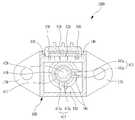
도 1은 본 발명의 일 실시예에 따른 리니어 센서에 대한 개략적인 사시도이다.
도 2는 본 발명의 일 실시예에 따른 리니어 센서에 대한 개략적인 분해사시도이다.
도 3은 본 발명의 일 실시예에 따른 리니어 센서의 상부 부분을 절개한 후의 개략적인 평면도이다.
도 4a 및 도 4b는 본 발명의 일 실시예에 따른 리니어 센서의 작동상태를 나타내는 개략적인 종단면도이다.1 is a schematic perspective view of a linear sensor according to an embodiment of the present invention.
2 is a schematic exploded perspective view of a linear sensor according to an embodiment of the present invention.
FIG. 3 is a schematic plan view after cutting an upper portion of a linear sensor according to an embodiment of the present invention. FIG.
4A and 4B are schematic longitudinal cross-sectional views illustrating an operating state of the linear sensor according to an embodiment of the present invention.
이하, 본 발명의 바람직한 실시예를 첨부한 도면을 참조하여 당해 분야의 통상의 지식을 가진 자가 용이하게 실시할 수 있도록 설명하기로 한다. 또한, 본 발명을 설명함에 있어 관련된 공지의 기능 또는 공지의 구성에 대한 구체적인 설명이 본 발명의 요지를 불필요하게 흐릴 수 있다고 판단되는 경우에는 그 상세한 설명을 생략하기로 한다. 그리고 도면에 제시된 어떤 특징들은 설명의 용이함을 위해 확대 또는 축소 또는 단순화된 것이고, 도면 및 그 구성요소들이 반드시 적절한 비율로 도시되어 있지는 않다. 그러나 당업자라면 이러한 상세 사항들을 쉽게 이해할 것이다.Hereinafter, preferred embodiments of the present invention will be described with reference to the accompanying drawings so that those skilled in the art can easily carry out the present invention. In the following description of the present invention, a detailed description of known functions and configurations incorporated herein will be omitted when it may make the subject matter of the present invention rather unclear. And certain features shown in the drawings are to be enlarged or reduced or simplified for ease of explanation, and the drawings and their components are not necessarily drawn to scale. However, those skilled in the art will readily understand these details.
참고로, 도 1, 도 2, 도 4a 및 도 4b를 기준으로, 도면의 윗 쪽을 향하는 방향 및 윗쪽을 향하는 부분을 리니어 센서의 상부방향 및 상부부분(또는 상부)이라고 정의하고, 도면의 아래쪽을 향하는 방향 및 아래쪽을 향하는 부분을 리니어 센서의 하부방향 및 하부부분(또는 하부)이라고 정의하기로 한다.For reference, with reference to Figs. 1, 2, 4A and 4B, upper and upper portions of the linear sensor are defined as upper and upper portions (or upper portions) And a downward portion is defined as a lower portion and a lower portion (or lower portion) of the linear sensor.
도 1은 본 발명의 일 실시예에 따른 리니어 센서(1000)에 대한 개략적인 사시도이고, 도 2는 본 발명의 일 실시예에 따른 리니어 센서(1000)에 대한 개략적인 분해사시도이고, 도 3은 본 발명의 일 실시예에 따른 리니어 센서(1000)의 상부 부분을 절개한 후의 개략적인 평면도이고, 도 4a 및 도 4b는 본 발명의 일 실시예에 따른 리니어 센서(1000)의 작동상태를 나타내는 개략적인 종단면도이다.FIG. 1 is a schematic perspective view of a
도 1 내지 도 4b에 도시된 바와 같이, 본 발명의 일 실시예에 따른 리니어 센서(1000)는, 하우징(100)과, 상기 리니어 센서(1000)의 피감지대상의 이동에 따라 상기 하우징(100)에 대해 왕복 병진이동하는 변위부(400)와, 상기 변위부(400)에 의해 형성되는 자기장의 변화를 감지하는 센싱부(500)를 포함한다.1 to 4B, a
상기 하우징(100)은 내부에 수용공간(110)을 구비하도록 중공형 부재로 구성된다. 도 1 내지 도 4b에 도시된 바와 같이, 상기 하우징(100)은 예를 들어 중공 사각기둥 형상을 구비한다.The
상기 수용공간(110)은 변위부(400)의 슬리브 부재(410) 및 자력부재(430)를 수용하여 상기 슬리브 부재(410)와 상기 자력부재(430)를 외부와 격리한다. 상기 변위부(400)의 슬리브 부재(410) 및 자력부재(430)는 상기 수용공간(110) 내에서 피감지대상의 위치변화에 따라 상하로 왕복 병진이동한다.The
구체적으로, 상기 하우징(100)은 외향돌출부와, 제1 가이드부재(160)와, 고정부(170)와, 일측벽(120)과, 제2-2 가이드부재(180)를 포함하며, 상기 하우징(100)의 하부단부는 개방되어 있다.Specifically, the
상기 하우징(100)의 개방된 하부단부는 변위부(400)의 조립을 완료한 후 상기 하우징(100)의 수용공간(110)을 폐쇄하기 위한 하부 덮개부(200)를 탈착가능하게 구비한다.The opened lower end of the
바람직하게는, 상기 하부 덮개부(200)는 높이가 상이하게 복수 개 구비되어 리니어 센서(1000)의 측정범위에 따라 다양한 높이의 하부 덮개부(200)가 교체되어 하우징(100)에 장착될 수 있다. 따라서, 리니어 센서(1000)의 피감지대상의 종류에 따라 및/또는 측정범위에 따라 하부 덮개부(200)만 교체하면 되므로, 리니어 센서(1000)의 호환성을 향상시킬 수 있다.A plurality of the
상기 하부 덮개부(200)의 내측면에는 후술할 변위부(400)의 탄성부재(440)의 수평방향 이동을 구속하는 탄성부재(440)용 고정턱(210)이 구비된다.The inner side surface of the
상기 외향돌출부는 수용공간(110)에서 외측방향으로 돌출되도록 형상되며, 중공(中空)형상을 구비한다.The outwardly projecting portion is shaped to protrude outward in the
상기 외향돌출부의 내부에는 제1 가이드부재(160)가 고정적으로 수용된다. 상기 제1 가이드부재(160)는 소정 길이를 가지며, 상기 제1 가이드부재(160)를 상하로 관통하는 관통구를 구비한다. 상기 관통구는 상기 변위부(400)에 포함되는 접촉용 핀부재(420)의 외주면 일부분을 지지하도록 상기 접촉용 핀부재(420)의 직경과 동일한 직경을 구비한다.A
상기 제1 가이드부재(160)는 상기 관통공(161)을 통하여 상기 접촉용 핀부재(420)의 왕복 병진이동을 가이드한다.The
상기 제1 가이드부재(160)가 구비됨으로써, 피감지대상의 위치변화에 따라 실질적으로 왕복 병진이동하는 변위부(400)와 하우징(100) 사이의 마찰면적을 제1 가이드부재(160)의 관통공(161)의 내주면으로 제한할 수 있어 하우징(100)의 마모면적을 상당히 감소시킬 수 있다.Since the
바람직하게는, 상기 제1 가이드부재(160)는 금속물질로 구성될 수 있고, 더 바람직하게는 비상자성 금속물질로 구성될 수 있다. 상기 제1 가이드부재(160)를 금속물질로 구성함으로써, 변위부(400)의 접촉용 핀부재(420)와의 접촉부분에 대한 강성 및 내마모성을 상당히 향상시킬 수 있어 하우징(100)의 내마모성을 현저히 향상시킬 수 있고, 그 결과 리니어 센서(1000)의 내구성 및 수명을 현저히 향상시킬 수 있다. 또한, 상기 제1 가이드부재(160)를 비상자성 금속물질로 구성함으로써, 변위부(400)에 포함되는 자력부재(430)에 의해 형성되는 자기장에 노이즈가 발생하는 것을 방지하고 동시에 변위부(400)의 이동에 대해 자기적 간섭(자기적 인력 및 척력)을 제거할 수 있다.Preferably, the
상기 고정부(170)는 하우징(100)의 양측방향으로 뻗어있도록 형성되고, 체결공을 구비한다. 상기 고정부(170)는 피감지대상 및/또는 피감지대상의 주변 부품에 리니어 센서(1000)를 고정하는 역할을 한다.The
상기 하우징(100)의 일측벽(120)은 상기 일측벽(120)의 외측면에서 수용홈(130)을 구비하고, 상기 수용홈(130)은 내부에 센싱부(500)를 수용하는 공간을 형성한다. 이로 인해, 상기 센싱부(500)는 상기 하우징(100)의 일측벽(120)의 외측면에 배치될 수 있어, 변위부(400)의 수용공간(110)과는 격리된 공간에 배치될 수 있다.One
이렇게 센싱부(500)와 변위부(400)를 완전히 별개의 공간에 격리시킴으로써, 각종 전장부품을 포함하는 센싱부(500)에 변위부(400)의 작동으로 인해 수반되는 이물질이 유입되는 것을 방지할 수 있다.By isolating the
또한, 상기 하우징(100)의 일측벽(120)에는 상기 하우징(100)의 수용홈(130)을 폐쇄하는 측면 덮개부(300)가 장착된다. 상기 측면 덮개부(300)는 센싱부(500)의 단자에 연결되는 케이블들이 인출될 수 있도록 하는 인출구(310)를 구비한다.A
바람직하게는, 상기 측면 덮개부(300)의 테두리와 상기 하우징(100)의 일측벽(120)의 테두리에는 밀봉재로 접착처리될 수 있다. 이때, 바람직하게는, 상기 밀봉재는 UV접착제일 수 있다. 따라서, 센싱부(500)와 변위부(400)를 완전히 별개의 공간에 격리키시고 상기 센싱부(500)를 밀봉함으로써, 각종 전장부품을 포함하는 센싱부(500)에 이물질이 유입되는 것을 방지할 수 있으며, 이로 인해 센싱부(500)의 수명을 향상시킬 수 있고, 결과적으로 리니어 센서(1000)의 내구성 및 수명을 보다 더 향상시킬 수 있다.The rim of the
그리고, 상기 하우징(100)의 일측벽(120)의 외측면에는 상기 외측면에 수직으로 형성되는 복수 개의 구속용 돌기(140)가 구비된다. 상기 복수 개의 구속용 돌기(140)는 후술할 센싱부(500)에 구비되는 복수 개의 구속용 개구(511)에 대응되는 구성으로서, 상기 복수 개의 구속용 개구(511)를 관통하도록 구성된다.A plurality of restricting
바람직하게는, 상기 복수 개의 구속용 돌기(140)의 외경과 상기 복수 개의 구속용 개구(511)의 내경은 동일할 수 있다.Preferably, the outer diameter of the plurality of restraining
이렇게, 구속용 돌기(140) 및 구속용 개구(511)를 통하여 센싱부(500)가 하우징(100)의 수용홈(130) 내에서 안정적으로 고정될 수 있고, 이로 인해 외부의 진동 등과 같은 외력이 리니어 센서(1000)에 가해지는 경우라도 센싱부(500)의 위치가 틀어지는 것을 방지할 수 있으므로, 리니어 센서(1000)의 감지 정확도를 향상시킬 수 있다.The
또한, 상기 하우징(100)은 상기 하우징(100)의 내측면에서부터 상기 수용공간(110) 쪽을 향해서 상기 하우징(100)의 길이방향을 따라서 뻗어있는 제2-2 가이드부재(180)를 적어도 하나 이상 구비한다.The
상기 제2-2 가이드부재(180)는 후술할 변위부(400)에 구비되는 제2-1 가이드부재(413)의 상기 한 쌍의 가이드용 돌출부(413a) 사이에 삽입되도록 형성되고, 상기 한 쌍의 가이드용 돌출부(413a)와 연동하여 상기 변위부(400)가 자축회전하는 것을 방지할 수 있다. 상기 제2-2 가이드부재(180)는 예를 들어 도 3에 도시된 바와 같이 원주 방향으로 90° 간격으로 두 개 구비될 수 있다.The second-
변위부(400)는 하우징(100)에 대해 왕복 병진이동하도록 구성되며, 피감지대상에 직접적으로 접촉하여 상기 피감지대상의 변위에 따라 함께 이동하도록 구성된다.The
구체적으로, 상기 변위부(400)는 슬리브부재(410)와, 접촉용 핀부재(420)와, 자력부재(430)와, 탄성부재(440)를 포함한다.Specifically, the
상기 접촉용 핀부재(420)는 상기 하우징(100)의 수용공간(110) 내부에서 상기 하우징(100)의 외부로 돌출되도록 연장되며, 상기 하우징(100)의 외부 및 내부(즉, 수용공간(110))를 왕복 이동하며 실질적으로 피감지대상에 접촉하는 단부를 구비한다. 상기 접촉용 핀부재(420)는 신장형 원기둥 형상을 구비한다. 상기 접촉용 핀부재(420)의 일부분은 전술한 바와 같이 상기 제1 가이드부재(160)의 관통공(161)에 의해 지지되면서 상하로 이동되며, 이로 인해 접촉용 핀부재(420)는 상하 수직방향의 이동(즉, Z축 이동)이외에는 수평방향으로의 이동(즉, X축 이동 및/또는 Y축 이동)이 완전히 제한됨으로써, 자력부재(430)가 피감지대상의 위치변화방향에 대해서만 이동하도록 할 수 있다. 그 결과, 리니어 센서(1000)의 감지 정확도를 현저히 향상시킬 수 있다.The
바람직하게는, 상기 접촉용 핀부재(420)는 금속물질로 구성될 수 있고, 더 바람직하게는 비상자성 금속물질로 구성될 수 있다. 상기 접촉용 핀부재(420)를 금속물질로 구성함으로써, 제1 가이드부재(160)와의 접촉부분(즉, 관통공(161))에 대한 강성 및 내마모성을 상당히 향상시킬 수 있다. 또한, 상기 접촉용 핀부재(420)를 비상자성 금속물질로 구성함으로써, 상기 자력부재(430)에 의해 형성되는 자기장에 노이즈가 발생하는 것을 방지하고 동시에 자력부재(430)의 이동에 대해 자기적 간섭(자기적 인력 및 척력)을 제거할 수 있다.Preferably, the
상기 자력부재(430)는 원통형상의 영구자석으로 구성되며, 접촉용 핀부재(420)의 상하 병진이동에 의해 수동적으로 상하 병진이동 되도록 구성된다. 상기 자력부재(430)는 자기장을 형성하며, 이렇게 형성된 자기장이 자력부재(430)의 이동으로 인해 고정된 위치에 있는 센싱부(500)에 자기장 변화를 감시시킴으로써 피감지대상의 변위를 측정하게 한다.The
상기 슬리브부재(410)는 상기 하우징(100)의 수용공간(110) 내에서 상하 방향으로 왕복 병진운동하며, 상기 접촉용 핀부재(420)의 일단부를 고정하는 일단부와 상기 자력부재(430)를 내부에 수용하는 타단부를 포함한다. 즉, 상기 슬리브부재(410)는 상부부분에서 접촉용 핀부재(420)의 하부단부를 고정적으로 수용하고, 하부부분의 내부에 자력부재(430)를 고정적으로 수용한다.The
또한, 상기 슬리브부재(410)는 상부부분의 외주면에서 상기 슬리브부재(410)의 외경보다 큰 외경을 가지는 원주확장부(411)를 구비한다. 상기 원주확장부(411)는 탄성부재(440)의 상단부가 고정되는 부분으로서 상기 탄성부재(440)의 탄성복원력을 전달받는 부분이다.The
그리고, 상기 슬리브부재(410)는 상부부분에서 제2-1 가이드부재(413)를 적어도 하나 이상 구비한다. 상기 제2-1 가이드부재(413)는 상기 슬리브부재(410)의 외측면에서 외측 반경방향으로 서로 평행하게 뻗어있는 한 쌍의 가이드용 돌출부(413a)를 포함하며, 상기 한 쌍의 가이드용 돌출부(413a)는 서로 소정거리 이격되게 형성 및 배치된다.The
전술한 바와 같이, 상기 한 쌍의 가이드용 돌출부(413a) 사이에는 상기 하우징(100)의 제2-2 가이드부재(180)가 삽입되며, 상기 제2-1 가이드부재(413)는 상기 제2-2 가이드부재(180)를 따라 상하로 병진이동하도록 가이드된다.As described above, the second-
상기 한 쌍의 가이드용 돌출부(413a)(즉, 제2-1 가이드부재(413))와 상기 제2-2 가이드부재(180)가 연동하여 상기 변위부(400)가 하우징(100)에 의해 회전이 구속되므로 상기 변위부(400)가 자축회전하는 것을 방지할 수 있다. 상기 제2-1 가이드부재(413)는 예를 들어 도 3에 도시된 바와 같이 원주 방향으로 90° 간격으로 두 개 구비될 수 있다.The pair of guide protrusions 413a (that is, the second-second guide member 413) and the second-
따라서, 변위부(400)가 피감지대상의 위치변화방향으로만 병진이동하도록 구속하고 동시에 변위부(400)가 자축회전하는 것을 확실히 방지함으로써, 자력부재(430)에 의해 형성되는 자기장의 변화가 피감지대상의 위치변화에만 의존하도록 할 수 있고, 이로 인해 리니어 센서(1000)의 감지 정확도를 현저히 향상시킬 수 있다.Therefore, by restraining the
센싱부(500)는 상기 하우징(100)에 고정적으로 구비되며, 상기 변위부(400)의 병진이동에 따른 상기 자력부재(430)와의 상대위치 변화로 인해 자기장 변화를 감지한다.The
전술한 바와 같이, 상기 센싱부(500)는 상기 하우징(100)의 일측벽(120)의 외측면에 구비되는 수용홈(130) 내에 고정된다.As described above, the
상기 센싱부(500)는 인쇄회로기판(510)과, 상기 인쇄회로기판(510)에서 내측방향면 상에 설치되어 상기 자력부재(430)와의 상대위치 변화로 인한 자기장의 변화를 감지하는 홀소자(520)(Hall element)와, 상기 인쇄회로기판(510)의 외측방향면과 상기 측면 덮개부(300)의 내측방향면 사이에 구비되어 외부의 전자파 및 노이즈를 차단하는 차폐부재(530)를 포함한다.The
상기 센싱부(500)의 인쇄회로기판(510)은 하우징(100)의 일측벽(120)의 외측면에 구비되는 복수 개의 구속용 돌기(140)가 관통하는 복수 개의 구속용 개구(511)를 구비한다. 이로 인해, 홀소자(520)는 하우징(100)에서 안정적으로 위치를 고정할 수 있고, 이로 인해 홀소자(520)의 위치 틀어짐 등으로 인한 자력부재(430)와 홀소자(520)의 상대위치 변화를 제거할 수 있어, 리니어 센서(1000)의 감지 정확도를 보다 향상시키고 감지 안정성도 함께 향상시킬 수 있다.The printed
전술한 바에 의하면, 본 발명은 제1 가이드부재를 구비함으로써, 피감지대상의 위치변화에 따라 실질적으로 왕복 병진이동하는 변위부와 하우징 사이의 마찰면적을 제1 가이드부재의 관통공을 제한할 수 있어 하우징의 마모면적을 상당히 감소시킬 수 있으며, 상기 제1 가이드부재를 금속물질로 구성함으로써 하우징의 내마모성을 현저히 향상시킬 수 있으며, 이로 인해 리니어 센서의 내구성 및 수명을 현저히 향상시킬 수 있다.According to the present invention, by providing the first guide member, the friction area between the displaceable portion, which is substantially reciprocally translationally moved in accordance with the positional change of the object to be sensed, and the housing can be restricted to the through hole of the first guide member And the abrasion resistance of the housing can be remarkably improved by constituting the first guide member with a metal material, thereby significantly improving the durability and service life of the linear sensor.
또한, 본 발명은 센싱부와 변위부를 완전히 별개의 공간에 격리키시고 상기 센싱부를 밀봉함으로써, 각종 전장부품을 포함하는 센싱부에 이물질이 유입되는 것을 방지할 수 있으며, 이로 인해 센싱부의 수명을 향상시킬 수 있고, 결과적으로 리니어 센서의 내구성 및 수명을 보다 더 향상시킬 수 있다.In addition, the present invention can isolate the sensing portion and the displacement portion from each other in a completely separate space and seal the sensing portion, thereby preventing foreign matter from flowing into the sensing portion including various electrical components, thereby improving the life of the sensing portion And as a result, the durability and lifetime of the linear sensor can be further improved.
또한, 본 발명은 제1 가이드부재 및/또는 제2-1 가이드부재 및 제2-2 가이드부재를 구비함으로써, 변위부가 피감지대상의 위치변화방향으로만 병진이동하도록 구속하고 동시에 변위부가 자축회전하는 것을 확실히 방지함으로써, 자력부재에 의해 형성되는 자기장의 변화가 피감지대상의 위치변화에만 의존하도록 할 수 있고, 이로 인해 리니어 센서의 감지 정확도를 현저히 향상시킬 수 있다.Further, according to the present invention, since the first guide member and / or the second-second guide member and the second-second guide member are provided, the displacement portion is constrained to translate only in the direction of change in the position of the object to be detected, The change of the magnetic field formed by the magnetic force member can be made to depend only on the change of the position of the object to be sensed, thereby making it possible to remarkably improve the detection accuracy of the linear sensor.
이상에서 본 발명의 기술적 사상을 예시하기 위해 구체적인 실시 예로 도시하고 설명하였으나, 본 발명은 상기와 같이 구체적인 실시 예와 동일한 구성 및 작용에만 국한되지 않고, 여러가지 변형이 본 발명의 범위를 벗어나지 않는 한도 내에서 실시될 수 있다. 따라서, 그와 같은 변형도 본 발명의 범위에 속하는 것으로 간주해야 하며, 본 발명의 범위는 후술하는 특허청구범위에 의해 결정되어야 한다.While the present invention has been particularly shown and described with reference to exemplary embodiments thereof, it is to be understood that the invention is not limited to the disclosed exemplary embodiments, . ≪ / RTI > Accordingly, such modifications are deemed to be within the scope of the present invention, and the scope of the present invention should be determined by the following claims.
1000 : 리니어 센서
100 : 하우징
200 : 하부 덮개부
300 : 측면 덮개부
400 : 변위부
500 : 센싱부1000: Linear sensor
100: Housing
200: Lower cover part
300: side cover portion
400: Displacement part
500: sensing part
Claims (11)
Translated fromKorean내부에 배치되는 자력부재와, 상기 하우징의 수용공간 내부에서 상기 하우징의 외부로 돌출되도록 연장되는 접촉용 핀부재를 포함하며, 상기 접촉용 핀부재의 단부에 접촉되는 피감지대상의 변위에 따라 상기 하우징에 대해 왕복 병진이동하는 변위부와;
상기 하우징의 일측벽의 외측면에 배치되어 고정적으로 구비되며, 상기 변위부의 병진이동에 따른 상기 자력부재와의 상대위치 변화로 인해 자기장 변화를 감지하는 센싱부;를 포함하고,
상기 변위부는, 상기 접촉용 핀부재의 일단부를 고정하는 일단부와 상기 자력부재를 내부에 수용하는 타단부를 포함하는 슬리브부재를 더 포함하는 것을 특징으로 하는 리니어 센서.A housing having a housing space therein;
And a contact pin member extending from the housing in the housing space so as to protrude out of the housing, wherein the contact pin member contacts the end of the contact pin member, A displacing portion reciprocally translationally moved with respect to the housing;
And a sensing unit fixedly disposed on an outer surface of a side wall of the housing and sensing a change in magnetic field due to a relative positional change with respect to the magnetic force member due to the translational movement of the displacement unit,
Wherein the displaceable portion further comprises a sleeve member including one end portion for fixing one end of the contact pin member and the other end portion for receiving the magnetic force member therein.
상기 센싱부는 상기 하우징의 일측벽의 외측면에 형성된 수용홈 내에 배치되는 것을 특징으로 하는 리니어 센서.The method according to claim 1,
Wherein the sensing unit is disposed in a receiving groove formed on an outer surface of a side wall of the housing.
상기 하우징의 수용홈을 폐쇄하는 측면 덮개부를 더 포함하는 것을 특징으로 하는 리니어 센서.The method according to claim 1,
Further comprising a side cover portion closing the housing groove of the housing.
상기 측면 덮개부의 테두리와 상기 하우징의 일측벽의 테두리에는 밀봉재로 접착처리되는 것을 특징으로 하는 리니어 센서.The method of claim 3,
Wherein the edge of the side cover and the edge of one side wall of the housing are bonded with a sealing material.
상기 센싱부는 인쇄회로기판과, 상기 인쇄회로기판에서 내측방향면 상에 설치되어 상기 자력부재와의 상대위치 변화로 인한 자기장의 변화를 감지하는 홀소자와, 상기 인쇄회로기판의 외측방향면과 상기 측면 덮개부의 내측방향면 사이에 구비되어 외부의 전자파 및 노이즈를 차단하는 차폐부재를 포함하는 것을 특징으로 하는 리니어 센서.The method of claim 3,
The sensing unit includes a printed circuit board, a Hall element mounted on an inner surface of the printed circuit board to sense a change in a magnetic field due to a change in relative position between the magnetic force member and an outer surface of the printed circuit board, And a shielding member provided between the inner side surfaces of the side cover portions to shield electromagnetic waves and noise from the outside.
상기 하우징의 일측벽의 외측면에는 상기 외측면에 수직으로 형성되는 복수 개의 구속용 돌기가 구비되고,
상기 센싱부는 상기 복수 개의 구속용 돌기가 관통하는 복수 개의 구속용 개구를 구비하는 것을 특징으로 하는 리니어 센서.The method according to claim 1,
A plurality of constraining protrusions formed on the outer side surface of the one side wall of the housing perpendicularly to the outer side surface,
Wherein the sensing unit includes a plurality of constraining openings through which the plurality of constraining projections pass.
상기 하우징은, 상기 수용공간에서부터 외측방향으로 돌출된 중공(中空)형상의 외향 돌출부와, 상기 접촉용 핀부재의 외주면 일부분을 지지하도록 상기 접촉용 핀부재의 직경과 동일한 직경과 소정 길이를 가지는 관통공을 구비하고 상기 접촉용 핀부재의 왕복 병진이동을 가이드하도록 상기 외향 돌출부의 내부에 수용되는 제1 가이드부재를 포함하는 것을 특징으로 하는 리니어 센서.The method according to claim 1,
The housing includes: a hollow-shaped outward projection projecting outwardly from the accommodation space; and a through-hole having a diameter and a predetermined length equal to the diameter of the contact pin member to support a part of the outer circumferential surface of the contact- And a first guide member having a hole and accommodated in the inside of the outwardly projecting portion to guide the reciprocating movement of the contact pin member.
상기 접촉용 핀부재와 상기 제1 가이드부재는 비상자성(非常磁性) 금속으로 구성되는 것을 특징으로 하는 리니어 센서.8. The method of claim 7,
Wherein the contact pin member and the first guide member are made of a non-magnetic metal.
상기 슬리브부재 및 상기 하우징은 상기 변위부가 상기 변위부의 자축을 중심으로 회전하는 것을 방지하는 회전방지부를 더 포함하는 것을 특징으로 하는 리니어 센서.The method according to claim 1,
Wherein the sleeve member and the housing further include a rotation preventing portion that prevents the displacement portion from rotating about a self axis of the displacement portion.
상기 슬리브부재는, 상기 슬리브부재의 외측면에서 외측 반경방향으로 서로 평행하게 뻗어있으며 서로 소정거리 이격되게 형성된 한 쌍의 가이드용 돌출부를 포함하는 제2-1 가이드부재를 적어도 하나 이상 포함하고,
상기 하우징은, 상기 하우징의 내측면에서부터 상기 수용공간 쪽을 향해서 상기 하우징의 길이방향을 따라서 뻗어있고 상기 제2-1 가이드부재의 상기 한 쌍의 가이드용 돌출부 사이에 삽입되도록 형성된 제2-2 가이드부재를 적어도 하나 이상 포함하는 것을 특징으로 하는 리니어 센서.11. The method of claim 10,
The sleeve member may include at least one second-type guide member extending parallel to the outer radial direction of the outer surface of the sleeve member and including a pair of guide protrusions spaced apart from each other by a predetermined distance,
The housing includes a second-second guide formed to extend from the inner side of the housing toward the accommodation space along the longitudinal direction of the housing and inserted between the pair of guide protrusions of the second- And at least one member is included in the linear sensor.
Priority Applications (1)
| Application Number | Priority Date | Filing Date | Title |
|---|---|---|---|
| KR1020130158109AKR101524489B1 (en) | 2013-12-18 | 2013-12-18 | Linear sensor |
Applications Claiming Priority (1)
| Application Number | Priority Date | Filing Date | Title |
|---|---|---|---|
| KR1020130158109AKR101524489B1 (en) | 2013-12-18 | 2013-12-18 | Linear sensor |
Publications (1)
| Publication Number | Publication Date |
|---|---|
| KR101524489B1true KR101524489B1 (en) | 2015-06-02 |
Family
ID=53490862
Family Applications (1)
| Application Number | Title | Priority Date | Filing Date |
|---|---|---|---|
| KR1020130158109AExpired - Fee RelatedKR101524489B1 (en) | 2013-12-18 | 2013-12-18 | Linear sensor |
Country Status (1)
| Country | Link |
|---|---|
| KR (1) | KR101524489B1 (en) |
Cited By (2)
| Publication number | Priority date | Publication date | Assignee | Title |
|---|---|---|---|---|
| WO2022236359A1 (en)* | 2021-05-10 | 2022-11-17 | Sandvik Mining And Construction Australia (Production/Supply) Pty Ltd | Sensor assembly for use between a ground engaging tool and a bucket |
| IT202300011307A1 (en)* | 2023-06-05 | 2024-12-05 | Brembo Spa | LINEAR MAGNET ARRANGEMENT FOR ELECTRONICALLY ASSISTED BRAKING SYSTEMS |
Citations (2)
| Publication number | Priority date | Publication date | Assignee | Title |
|---|---|---|---|---|
| JPH05280916A (en)* | 1992-02-05 | 1993-10-29 | Mitsubishi Electric Corp | Straight line displacement detection device |
| JPH0849575A (en)* | 1994-08-08 | 1996-02-20 | Nippondenso Co Ltd | Operational quantity detection device for acceleration pedal |
- 2013
- 2013-12-18KRKR1020130158109Apatent/KR101524489B1/ennot_activeExpired - Fee Related
Patent Citations (2)
| Publication number | Priority date | Publication date | Assignee | Title |
|---|---|---|---|---|
| JPH05280916A (en)* | 1992-02-05 | 1993-10-29 | Mitsubishi Electric Corp | Straight line displacement detection device |
| JPH0849575A (en)* | 1994-08-08 | 1996-02-20 | Nippondenso Co Ltd | Operational quantity detection device for acceleration pedal |
Cited By (3)
| Publication number | Priority date | Publication date | Assignee | Title |
|---|---|---|---|---|
| WO2022236359A1 (en)* | 2021-05-10 | 2022-11-17 | Sandvik Mining And Construction Australia (Production/Supply) Pty Ltd | Sensor assembly for use between a ground engaging tool and a bucket |
| IT202300011307A1 (en)* | 2023-06-05 | 2024-12-05 | Brembo Spa | LINEAR MAGNET ARRANGEMENT FOR ELECTRONICALLY ASSISTED BRAKING SYSTEMS |
| WO2024252239A1 (en)* | 2023-06-05 | 2024-12-12 | Brembo S.P.A. | Arrangement for a linear magnet for electronically assisted braking systems |
Similar Documents
| Publication | Publication Date | Title |
|---|---|---|
| JP6715576B2 (en) | Switching device | |
| KR101415152B1 (en) | Electronic type shifter lever device | |
| US9863478B2 (en) | Motion guide device | |
| CN107421432B (en) | Non-contact Hall displacement sensor | |
| KR101524489B1 (en) | Linear sensor | |
| CN104246422A (en) | Sensor element for a measuring machine, in particular a coordinate measuring machine | |
| US7034526B2 (en) | Magnetic field forming device and displacement sensor using same | |
| JP5572017B2 (en) | Range detector | |
| US10444002B2 (en) | Sensor device for geometrically testing parts | |
| JP5993870B2 (en) | Encoder read head device | |
| CN105513893B (en) | Switch with a switch body | |
| EP3304004B1 (en) | An apparatus for sensing the position of an actuator assembly of a locking gearset | |
| JP2021536006A (en) | Stroke sensor with magnet holder and magnet holder | |
| EP3100911A1 (en) | Brake light sensor module | |
| US10447118B2 (en) | Motor apparatus | |
| KR20220129074A (en) | Sensor assembly, actuator for brake system | |
| JP6088345B2 (en) | connector | |
| CN107883861A (en) | Position sensor | |
| CN108151770B (en) | Encapsulated magnet position switch | |
| JP6242159B2 (en) | Length measuring instrument | |
| JP2009229418A (en) | Vibration sensor | |
| CN109312856A (en) | Speed changer with switch unit | |
| CN110691919A (en) | Central separator with sensor that can be inserted into housing, central separator with piston and magnet fixed to piston, and method for assembling same | |
| KR101545807B1 (en) | Accelerator pedal Position Sensor | |
| US20110290056A1 (en) | Locking/Unlocking Device |
Legal Events
| Date | Code | Title | Description |
|---|---|---|---|
| PA0109 | Patent application | St.27 status event code:A-0-1-A10-A12-nap-PA0109 | |
| PA0201 | Request for examination | St.27 status event code:A-1-2-D10-D11-exm-PA0201 | |
| D13-X000 | Search requested | St.27 status event code:A-1-2-D10-D13-srh-X000 | |
| D14-X000 | Search report completed | St.27 status event code:A-1-2-D10-D14-srh-X000 | |
| PE0902 | Notice of grounds for rejection | St.27 status event code:A-1-2-D10-D21-exm-PE0902 | |
| E13-X000 | Pre-grant limitation requested | St.27 status event code:A-2-3-E10-E13-lim-X000 | |
| P11-X000 | Amendment of application requested | St.27 status event code:A-2-2-P10-P11-nap-X000 | |
| P13-X000 | Application amended | St.27 status event code:A-2-2-P10-P13-nap-X000 | |
| PE0701 | Decision of registration | St.27 status event code:A-1-2-D10-D22-exm-PE0701 | |
| GRNT | Written decision to grant | ||
| PR0701 | Registration of establishment | St.27 status event code:A-2-4-F10-F11-exm-PR0701 | |
| PR1002 | Payment of registration fee | St.27 status event code:A-2-2-U10-U11-oth-PR1002 Fee payment year number:1 | |
| PG1601 | Publication of registration | St.27 status event code:A-4-4-Q10-Q13-nap-PG1601 | |
| P22-X000 | Classification modified | St.27 status event code:A-4-4-P10-P22-nap-X000 | |
| P22-X000 | Classification modified | St.27 status event code:A-4-4-P10-P22-nap-X000 | |
| R18-X000 | Changes to party contact information recorded | St.27 status event code:A-5-5-R10-R18-oth-X000 | |
| PN2301 | Change of applicant | St.27 status event code:A-5-5-R10-R13-asn-PN2301 St.27 status event code:A-5-5-R10-R11-asn-PN2301 | |
| FPAY | Annual fee payment | Payment date:20180524 Year of fee payment:4 | |
| PR1001 | Payment of annual fee | St.27 status event code:A-4-4-U10-U11-oth-PR1001 Fee payment year number:4 | |
| FPAY | Annual fee payment | Payment date:20190527 Year of fee payment:5 | |
| PR1001 | Payment of annual fee | St.27 status event code:A-4-4-U10-U11-oth-PR1001 Fee payment year number:5 | |
| PR1001 | Payment of annual fee | St.27 status event code:A-4-4-U10-U11-oth-PR1001 Fee payment year number:6 | |
| PC1903 | Unpaid annual fee | St.27 status event code:A-4-4-U10-U13-oth-PC1903 Not in force date:20210527 Payment event data comment text:Termination Category : DEFAULT_OF_REGISTRATION_FEE | |
| PC1903 | Unpaid annual fee | St.27 status event code:N-4-6-H10-H13-oth-PC1903 Ip right cessation event data comment text:Termination Category : DEFAULT_OF_REGISTRATION_FEE Not in force date:20210527 |