KR101524336B1 - Thin Flat Type Converge Lens - Google Patents
Thin Flat Type Converge LensDownload PDFInfo
- Publication number
- KR101524336B1 KR101524336B1KR1020110119190AKR20110119190AKR101524336B1KR 101524336 B1KR101524336 B1KR 101524336B1KR 1020110119190 AKR1020110119190 AKR 1020110119190AKR 20110119190 AKR20110119190 AKR 20110119190AKR 101524336 B1KR101524336 B1KR 101524336B1
- Authority
- KR
- South Korea
- Prior art keywords
- film
- light
- lens
- parallel
- transparent
- Prior art date
- Legal status (The legal status is an assumption and is not a legal conclusion. Google has not performed a legal analysis and makes no representation as to the accuracy of the status listed.)
- Expired - Fee Related
Links
Images


Classifications
- G—PHYSICS
- G02—OPTICS
- G02B—OPTICAL ELEMENTS, SYSTEMS OR APPARATUS
- G02B30/00—Optical systems or apparatus for producing three-dimensional [3D] effects, e.g. stereoscopic images
- G—PHYSICS
- G03—PHOTOGRAPHY; CINEMATOGRAPHY; ANALOGOUS TECHNIQUES USING WAVES OTHER THAN OPTICAL WAVES; ELECTROGRAPHY; HOLOGRAPHY
- G03H—HOLOGRAPHIC PROCESSES OR APPARATUS
- G03H1/00—Holographic processes or apparatus using light, infrared or ultraviolet waves for obtaining holograms or for obtaining an image from them; Details peculiar thereto
- G03H1/04—Processes or apparatus for producing holograms
- G03H1/0402—Recording geometries or arrangements
- G03H1/0404—In-line recording arrangement
- G—PHYSICS
- G02—OPTICS
- G02B—OPTICAL ELEMENTS, SYSTEMS OR APPARATUS
- G02B5/00—Optical elements other than lenses
- G02B5/20—Filters
- G02B5/203—Filters having holographic or diffractive elements
- G—PHYSICS
- G02—OPTICS
- G02B—OPTICAL ELEMENTS, SYSTEMS OR APPARATUS
- G02B5/00—Optical elements other than lenses
- G02B5/32—Holograms used as optical elements
- G—PHYSICS
- G03—PHOTOGRAPHY; CINEMATOGRAPHY; ANALOGOUS TECHNIQUES USING WAVES OTHER THAN OPTICAL WAVES; ELECTROGRAPHY; HOLOGRAPHY
- G03H—HOLOGRAPHIC PROCESSES OR APPARATUS
- G03H1/00—Holographic processes or apparatus using light, infrared or ultraviolet waves for obtaining holograms or for obtaining an image from them; Details peculiar thereto
- G03H1/22—Processes or apparatus for obtaining an optical image from holograms
- G03H1/2294—Addressing the hologram to an active spatial light modulator
- G—PHYSICS
- G03—PHOTOGRAPHY; CINEMATOGRAPHY; ANALOGOUS TECHNIQUES USING WAVES OTHER THAN OPTICAL WAVES; ELECTROGRAPHY; HOLOGRAPHY
- G03H—HOLOGRAPHIC PROCESSES OR APPARATUS
- G03H1/00—Holographic processes or apparatus using light, infrared or ultraviolet waves for obtaining holograms or for obtaining an image from them; Details peculiar thereto
- G03H1/02—Details of features involved during the holographic process; Replication of holograms without interference recording
- G03H2001/0208—Individual components other than the hologram
- G03H2001/0212—Light sources or light beam properties
- G—PHYSICS
- G03—PHOTOGRAPHY; CINEMATOGRAPHY; ANALOGOUS TECHNIQUES USING WAVES OTHER THAN OPTICAL WAVES; ELECTROGRAPHY; HOLOGRAPHY
- G03H—HOLOGRAPHIC PROCESSES OR APPARATUS
- G03H1/00—Holographic processes or apparatus using light, infrared or ultraviolet waves for obtaining holograms or for obtaining an image from them; Details peculiar thereto
- G03H1/04—Processes or apparatus for producing holograms
- G03H1/0402—Recording geometries or arrangements
- G03H2001/0413—Recording geometries or arrangements for recording transmission holograms
- G—PHYSICS
- G03—PHOTOGRAPHY; CINEMATOGRAPHY; ANALOGOUS TECHNIQUES USING WAVES OTHER THAN OPTICAL WAVES; ELECTROGRAPHY; HOLOGRAPHY
- G03H—HOLOGRAPHIC PROCESSES OR APPARATUS
- G03H1/00—Holographic processes or apparatus using light, infrared or ultraviolet waves for obtaining holograms or for obtaining an image from them; Details peculiar thereto
- G03H1/04—Processes or apparatus for producing holograms
- G03H1/0402—Recording geometries or arrangements
- G03H2001/0439—Recording geometries or arrangements for recording Holographic Optical Element [HOE]
- G—PHYSICS
- G03—PHOTOGRAPHY; CINEMATOGRAPHY; ANALOGOUS TECHNIQUES USING WAVES OTHER THAN OPTICAL WAVES; ELECTROGRAPHY; HOLOGRAPHY
- G03H—HOLOGRAPHIC PROCESSES OR APPARATUS
- G03H2222/00—Light sources or light beam properties
- G03H2222/10—Spectral composition
- G03H2222/17—White light
- G03H2222/18—RGB trichrome light
- G—PHYSICS
- G03—PHOTOGRAPHY; CINEMATOGRAPHY; ANALOGOUS TECHNIQUES USING WAVES OTHER THAN OPTICAL WAVES; ELECTROGRAPHY; HOLOGRAPHY
- G03H—HOLOGRAPHIC PROCESSES OR APPARATUS
- G03H2222/00—Light sources or light beam properties
- G03H2222/34—Multiple light sources
- G—PHYSICS
- G03—PHOTOGRAPHY; CINEMATOGRAPHY; ANALOGOUS TECHNIQUES USING WAVES OTHER THAN OPTICAL WAVES; ELECTROGRAPHY; HOLOGRAPHY
- G03H—HOLOGRAPHIC PROCESSES OR APPARATUS
- G03H2223/00—Optical components
- G03H2223/16—Optical waveguide, e.g. optical fibre, rod
- G—PHYSICS
- G03—PHOTOGRAPHY; CINEMATOGRAPHY; ANALOGOUS TECHNIQUES USING WAVES OTHER THAN OPTICAL WAVES; ELECTROGRAPHY; HOLOGRAPHY
- G03H—HOLOGRAPHIC PROCESSES OR APPARATUS
- G03H2223/00—Optical components
- G03H2223/17—Element having optical power
- G—PHYSICS
- G03—PHOTOGRAPHY; CINEMATOGRAPHY; ANALOGOUS TECHNIQUES USING WAVES OTHER THAN OPTICAL WAVES; ELECTROGRAPHY; HOLOGRAPHY
- G03H—HOLOGRAPHIC PROCESSES OR APPARATUS
- G03H2223/00—Optical components
- G03H2223/23—Diffractive element
- G—PHYSICS
- G03—PHOTOGRAPHY; CINEMATOGRAPHY; ANALOGOUS TECHNIQUES USING WAVES OTHER THAN OPTICAL WAVES; ELECTROGRAPHY; HOLOGRAPHY
- G03H—HOLOGRAPHIC PROCESSES OR APPARATUS
- G03H2226/00—Electro-optic or electronic components relating to digital holography
- G03H2226/05—Means for tracking the observer
Landscapes
- Physics & Mathematics (AREA)
- General Physics & Mathematics (AREA)
- Optics & Photonics (AREA)
- Stereoscopic And Panoramic Photography (AREA)
- Holo Graphy (AREA)
- Diffracting Gratings Or Hologram Optical Elements (AREA)
Abstract
Translated fromKoreanDescription
Translated fromKorean본 발명은 박막 평판형 수렴 렌즈에 관한 것이다. 특히, 본 발명은 홀로그래피 방식의 입체 영상 표시장치에서 입체 영상의 초점을 설정하기 위한 박막 평판형 수렴 렌즈에 관한 것이다.The present invention relates to a thin film flat type convergent lens. In particular, the present invention relates to a thin film flat type convergent lens for setting a focus of a stereoscopic image in a holographic stereoscopic image display apparatus.
최근 3차원 (3D: Three Dimension) 영상과 영상 재생 기술에 대한 연구들이 활발히 이루어지고 있다. 3차원 영상 관련 미디어는 시각 정보의 수준을 한 차원 더 높여주는 새로운 개념의 실감 영상 미디어로서 차세대 영상장치를 주도할 것으로 예상된다. 기존의 2차원 영상 시스템은 평면 영상을 제공하지만 3차원 영상 시스템은 물체가 가지고 있는 실제 이미지 정보를 관찰자에게 보여주는 관점에서 궁극적인 영상 구현 기술이라고 할 수 있다.Recently, three dimensional (3D) image and image reproduction techniques have been actively studied. 3D image related media is expected to lead the next generation imaging device as a realistic image media with a new concept that raises the level of visual information one more level. The conventional 2D image system provides the plane image, but the 3D image system is the ultimate image realization technology in terms of showing the actual image information of the object to the observer.
3차원 입체 영상을 재생하기 위한 방법으로는 크게, 안경방식(stereoscopy), 무안경 방식(Auto-stereoscopy), 체적형 방식(Volumetric), 홀로그래피 (holography) 및 집적영상 (integral imaging) 등의 방법들이 연구 개발되고 있다. 이 중에서 홀로그래피 방식은 레이저를 이용하여 제작한 홀로그래피를 관측시 특수 안경을 장착하지 않고도 실물과 가장 유사하게 입체감을 느낄 수 있는 방식이다. 따라서, 홀로그래피 방식은 입체감이 뛰어나며 단안으로도 입체감을 느낄 수 있는 특징이 있어, 관측자가 피로감 없이 입체 영상을 느낄 수 있는 가장 이상적인 방식으로 알려져 있다.Methods for reproducing three-dimensional stereoscopic images include a stereoscopic method, an auto-stereoscopy method, a volumetric method, a holography method, and an integral imaging method Research and development. Among them, the holography method is a method which can feel the stereoscopic feeling most like the real without observing the special glasses when observing the holography produced by the laser. Therefore, the holography method is excellent in three-dimensional feeling and has a characteristic of feeling a stereoscopic effect even in a single view, and it is known as an ideal method for an observer to feel a stereoscopic image without fatigue.
홀로그래피 방식은 물체에서 반사된 빛(물체파)과 간섭성이 있는 빛(기준파)을 겹쳐서 얻어지는 간섭신호를 기록하고 이를 재생하는 원리를 이용하는 것이다. 가간섭성이 높은 레이저 광을 사용하여 물체에 부딪쳐 산란되는 물체파를 또 다른 방향에서 입사된 기준파와 만나게 하여 형성된 간섭 무늬를 산진 필름에 기록한다. 물체파와 기준파가 만날 때, 간섭에 의한 간섭 무늬를 형성하는데, 이 간섭 무늬에 물체의 진폭과 위상 정보가 함께 기록된다. 이렇게 기록된 간섭 무늬에 참조광을 조사하여 홀로그램에 기록된 간섭 정보를 복원해 3차원적인 입체감을 느끼게 해준다. 이러한 기록 및 복원 원리를 사용해 3차원 영상을 구현하는 일련의 과정을 홀로그래피라고 한다.The holographic method uses the principle of recording and reproducing an interference signal obtained by superimposing light (object wave) reflected from an object and light (reference wave) having coherence. An interference fringe formed by causing an object wave scattered by an object to collide with a reference wave incident from another direction is recorded on the scattered film by using a highly coherent laser beam. When an object wave and a reference wave meet, an interference fringe due to interference is formed. The amplitude and phase information of the object are also recorded in this fringe pattern. By irradiating reference light to the interference fringes recorded in this manner, the interference information recorded in the hologram is restored, and the three-dimensional stereoscopic effect is felt. A series of processes for implementing a three-dimensional image using such a recording and restoration principle is called holography.
홀로그램을 저장, 전송 및 영상처리를 위해 컴퓨터에 의해 생성하는 방법으로서, 컴퓨터 생성 홀로그램(CGH: Computer Generated Hologram)이 개발되었다. 이 컴퓨터 생성 홀로그램은 지금까지 다양한 방법으로 개발되고 있는데, 근래에는 디지털 산업의 발달에 의해 정지 영상의 컴퓨터 생성 홀로그램에 머무르지 않고 동영상의 컴퓨터 생성 홀로그램을 표시하기 위한 시스템이 개발되고 있다.A computer generated hologram (CGH) has been developed as a method for computer generated holograms for storage, transmission and image processing. This computer-generated hologram has been developed in various ways so far. Recently, a system for displaying a computer-generated hologram of a moving image without developing a computer-generated hologram of a still image has been developed due to the development of the digital industry.
컴퓨터 생성 홀로그램은 컴퓨터를 이용하여 직접 홀로그램에 저장되는 간섭무늬를 만드는 것으로. 간섭 무늬 이미지를 컴퓨터로 계산하여 생성한 후, 액정 - 공간 광 변조기(LC-SLM: Liquid Crystal - Spatial Light Modulator)와 같은 공간 광 변조기에 전송하고, 이 SLM에 참조광을 조사하여 입체 영상을 복원/재생한다. 도 1은 종래 기술에 의한 컴퓨터 생성 홀로그램 방식을 구현한 디지털 홀로그램 영상 재생 장치의 구성을 나타내는 도면이다.A computer generated hologram is an interference pattern that is stored directly in a hologram using a computer. The interference fringe image is generated by a computer and then transmitted to a spatial light modulator such as a liquid crystal-spatial light modulator (LC-SLM), and the reference light is irradiated to the SLM to restore / Playback. 1 is a block diagram of a digital hologram image reproducing apparatus embodying a computer generated hologram method according to the related art.
도 1을 참조하면, 컴퓨터(10)에서 구현하고자 하는 입체 영상에 해당하는 간섭 무늬 이미지를 생성한다. 생성된 간섭 무늬는 SLM(20)으로 전송된다. SLM(20)은 투과형 액정표시패널로 형성하여 간섭 무늬를 표시할 수 있다. SLM(20)의 일측면에는 참조광으로 사용할 레이저 광원(30)이 위치해 있다. 레이저 광원(30)에서 조사되는 참조광(90)을 SLM(20)의 전면에 고르게 투사하기 위해서 확장기(40)와 렌즈(50)가 순차적으로 배치된다. 레이저 광원(30)에서 출사된 참조광(90)은, 확장기(40)와 렌즈(50)를 거쳐 SLM(20)의 일측면에 조사된다. SLM(20)이 투과형 액정표시 패널인 경우, SLM(20)의 타측면에는 SLM(20)에 구현된 홀로그램의 간섭 무늬에 의해 3차원 입체 영상(80)이 표시된다.Referring to FIG. 1, an interference fringe image corresponding to a stereoscopic image to be implemented in the
도 1에 의한 홀로그래피 방식의 입체 영상 표시장치는 참조광(90)을 발생하는 광원(30), 확장기(40) 그리고 렌즈(50)와 같이 상당한 부피를 차지하는 구성품으로 이루어진다. 이와 같은 시스템을 구축하는 경우, 부피가 상당히 크며, 무게도 많이 나가기 때문에, 최근 추세인 경박단소형의 표시장치에는 적합하지 않다. 따라서, 무안경 방식으로 궁극적인 입체 영상을 구현하는 홀로그래피 방식의 입체 영상 시스템을 박막 평판형으로 구현하는 것이 요구되고 있다.The holographic stereoscopic image display apparatus shown in FIG. 1 includes a
특히, 홀로그래피 방식의 입체 영상 장치의 핵심 구성 요소인 SLM을 박막형으로 구현하였다고 하더라도, 입체 영상의 초점을 맞추기 위해 전통적인 볼록 렌즈를 사용할 경우, 박막형으로 구현할 수 없다. 더구나, 입체 영상 표시장치를 대화면으로 구현하는 경우, 렌즈 역시 대화면에 대응하는 크기를 가져야 하는데, 전통적인 렌즈는 크기가 커질수록 두께도 두꺼워지고 무게도 사용하기에는 너무 무거워져서 박막 평판형 입체 영상 표시장치에는 적용하기가 어렵다.Particularly, even if SLM, which is a core component of a holographic stereoscopic image device, is implemented as a thin film, it can not be realized as a thin film type when a conventional convex lens is used to focus the stereoscopic image. In addition, when the stereoscopic image display device is implemented as a large screen, the lens must have a size corresponding to a large screen. As the size of the conventional lens increases, the thickness becomes thicker and the weight becomes too heavy to use. It is difficult to apply.
본 발명의 목적은 상기 문제점들을 극복하기 위해 고안된 것으로, 빛의 진행 방향에 대해 수평한 입사각으로 진행하는 평면파를 진행 축의 임의의 점에 수렴시키는 박막 평판형 렌즈를 제공하는 데 있다. 본 발명의 다른 목적은, 박막 평판형 홀로그래피 방식의 입체 영상 표시장치에 적용할 박막 평판형 수렴 렌즈를 제공하는 데 있다.SUMMARY OF THE INVENTION It is an object of the present invention to provide a thin film flat type lens which is designed to overcome the above problems and which converges plane waves traveling at a horizontal incident angle with respect to the traveling direction of light to an arbitrary point on the traveling axis. It is another object of the present invention to provide a thin film flat type convergent lens to be applied to a thin film flat type holographic stereoscopic image display apparatus.
상기 본 발명의 목적을 달성하기 위해, 본 발명에 의한 박막 평판형 수렴 렌즈는, 투명 기판; 그리고 상기 투명 기판의 일측면에 부착된 투명 필름에 간섭 무늬가 형성된 필름 렌즈를 포함한다.In order to achieve the object of the present invention, the thin film flat type convergent lens according to the present invention comprises: a transparent substrate; And a film lens having an interference pattern formed on a transparent film attached to one side of the transparent substrate.
상기 간섭 무늬는, 상기 투명 기판의 수선축에 대해 경사각도를 갖고 입사되는 경사 직진광을 상기 수선축에 평행하게 진행하는 평행 직진 출사광으로 변환하는 간섭 무늬를 갖는 마스터 필름을 동시에 통과하는 수렴광과 상기 경사 직진광의 간섭 무늬인 것을 특징으로 한다.Wherein the interference fringe is a convergent light beam having an inclination angle with respect to a water-repelling axis of the transparent substrate and passing through the master film having an interference fringe that converts incident incidence straight-on light into parallel straight- And an interference fringe of the obliquely linear light.
상기 경사 직진광은, 상기 경사 각도가 상기 수선축에 대하여 45도 ± 30도 범위의 어느 한 값을 갖는 것을 특징으로 한다.And the inclined straight line light has a value of the inclination angle within a range of 45 degrees +/- 30 degrees with respect to the waterline axis.
상기 수렴광은, 상기 마스터 필름의 일측면에서 상기 수선축에 평행하게 입사되는 제2 평행 직진광을, 상기 수선축 상에서 초점이 설정된 볼록 렌즈를 통과하여 형성한 것을 특징으로 한다.And the convergent light is formed by passing a second parallel straight-line light incident on one side of the master film in parallel to the water-repellent axis, through a convex lens focused on the water-repellent axis.
상기 초점은 상기 마스터 필름의 광 입사면 상에 설정한 것을 특징으로 한다.And the focal point is set on the light incident surface of the master film.
상기 필름 렌즈는 500μm 이하의 두께를 갖는 광반응 특성을 갖는 필름을 포함하는 것을 특징으로 한다.Wherein the film lens comprises a film having a photoreaction characteristic with a thickness of 500 탆 or less.
상기 필름 렌즈는, 투명한 포토폴리머 (photopolymer) 및 투명한 젤라틴(gelatine) 중 적어도 어느 하나를 포함하는 것을 특징으로 한다.The film lens includes at least one of a transparent photopolymer and a transparent gelatin.
상기 투명 기판 그리고 상기 필름 렌즈는 굴절율이 동일한 것을 특징으로 한다.Wherein the transparent substrate and the film lens have the same refractive index.
본 발명에 의한 수렴 렌즈는, 간섭 무늬를 포함하는 한 장의 박막 필름형 수렴 렌즈를 제공한다. 따라서, 입체 영상 표시장치를 구현함에 있어서, 박막 필름형 렌즈를 이용하여 공간상에 혹은 시청자의 눈(동공)에 입체 영상의 초점을 설정할 수 있다. 즉, 홀로 그래픽 방식의 입체 표시장치를 박막 평판형으로 구현할 수 있다. 또한, 본 발명에 의한 수렴 렌즈는 박막 필름형이므로 대형 대각 화면을 갖는 입체 영상 표시장치에 적용하더라도 무게가 가볍고 두께가 극히 얇다는 장점이 있다.A converging lens according to the present invention provides a single thin film type converging lens including an interference fringe. Therefore, in realizing the stereoscopic image display device, it is possible to set the focus of the stereoscopic image on the space or on the viewer's eyes (pupil) by using the thin film type lens. That is, the holographic stereoscopic display device can be realized as a thin film flat plate type. Further, since the converging lens according to the present invention is a thin film type, it is advantageous in that it is light in weight and extremely thin even when applied to a stereoscopic image display device having a large diagonal screen.
도 1은 종래 기술에 의한 컴퓨터 생성 홀로그램 방식을 구현한 디지털 홀로그램 영상 재생 장치의 구성을 나타내는 도면.
도 2는 본 발명의 제1 실시 예에 의한 투과형 액정표시장치를 이용한 디지털 홀로그래피 방식의 입체 영상 표시 장치의 구조를 나타내는 개략도.
도 3은 본 발명의 제1 실시 예에 의한 평행 직진광과 수렴광을 투명 기록 매질에 동시에 조사하여 간섭 패턴을 기록하는 방법을 도시한 도면.
도 4는 도 3에 의해 형성된 박막 평판형 수렴 렌즈에 의해 평행 직진광이 수렴되는 것을 보여주는 도면.
도 5는 본 발명의 제2 실시 예에 의한 박막 평판형 수렴 렌즈(FL)의 구조를 나타내는 단면도.
도 6a는 필름 렌즈(PL)를 형성하기 위한 마스터 필름(MP)을 제조하는 방법을 나타내는 개략도.
도 6b는 마스터 필름(MP)을 이용하여 필름 렌즈(PL)를 제조하는 방법을 나타내는 개략도.
도 7a는 필름 렌즈를 이용하여 평행 직진광이 수렴광으로 바꾸는 과정을 보여주는 광 경로를 나타내는 도면.
도 7b는 필름 렌즈를 이용하여 발산광이 평행 직진광으로 바꾸는 과정을 보여주는 광 경로를 나타내는 도면.
도 8은 본 발명의 제2 실시 예에 의해 제조한 박막 평판형 수렴 렌즈(FL)를 구비한 홀로그래피 방식의 입체 영상 표시장치에서 입체 영상이 관람자의 눈에 초점이 설정된 상태를 나타낸 개략도.BRIEF DESCRIPTION OF THE DRAWINGS Fig. 1 is a view showing a configuration of a digital hologram image reproducing apparatus embodying a computer generated hologram system according to the prior art; Fig.
BACKGROUND OF THE INVENTION 1. Field of the Invention [0001] The present invention relates to a stereoscopic image display device, and more particularly to a stereoscopic image display device using a transmissive liquid crystal display device.
3 is a diagram showing a method of recording an interference pattern by simultaneously irradiating a transparent recording medium with a parallel straight beam and a converging light according to the first embodiment of the present invention.
Fig. 4 is a view showing parallel convergent light converged by a thin film flat type converging lens formed by Fig. 3; Fig.
5 is a sectional view showing the structure of a thin film flat type converging lens FL according to a second embodiment of the present invention.
6A is a schematic view showing a method of manufacturing a master film (MP) for forming a film lens PL;
6B is a schematic view showing a method of manufacturing a film lens PL using a master film (MP).
7A is a view showing a light path showing a process of converting parallel straight-line light into converged light using a film lens;
7B is a view showing a light path showing a process of converting divergent light into parallel straight light using a film lens;
FIG. 8 is a schematic view showing a state in which a stereoscopic image is focused on a spectator's eye in a holographic stereoscopic image display device provided with a thin film flat type converging lens FL manufactured by a second embodiment of the present invention. FIG.
이하, 첨부한 도면들, 도 2 내지 8을 참조하여, 본 발명의 바람직한 실시 예를 설명한다. 명세서 전체에 걸쳐서 동일한 참조 번호들은 실질적으로 동일한 구성 요소들을 의미한다. 이하의 설명에서, 본 발명과 관련된 공지 기술 혹은 구성에 대한 구체적인 설명이 본 발명의 요지를 불필요하게 흐릴 수 있다고 판단되는 경우, 그 상세한 설명을 생략한다.Hereinafter, a preferred embodiment of the present invention will be described with reference to the accompanying drawings, FIGS. 2 to 8. FIG. Like reference numerals throughout the specification denote substantially identical components. DETAILED DESCRIPTION OF THE PREFERRED EMBODIMENTS In the following description, a detailed description of known technologies or configurations related to the present invention will be omitted when it is determined that the gist of the present invention may be unnecessarily obscured.
먼저, 도 2를 참조하여, 본 발명의 제1 실시 예에 의한, 투과형 액정표시장치를 공간 광 변조기로 사용한 박막 평판형 홀로그래피 방식의 입체 영상 표시장치를 설명한다. 도 2는 본 발명의 제1 실시 예에 의한 투과형 액정표시장치를 이용한 디지털 홀로그래피 방식의 입체 영상 표시 장치의 구조를 나타내는 개략도이다.First, referring to FIG. 2, a thin film flat panel holographic stereoscopic image display apparatus using a transmissive liquid crystal display device as a spatial light modulator according to a first embodiment of the present invention will be described. 2 is a schematic view showing the structure of a stereoscopic image display apparatus using a digital holography method using a transmissive liquid crystal display according to a first embodiment of the present invention.
본 발명의 제1 실시 예에 의한 홀로그래피 방식의 입체 영상 표시장치는 SLM(200)을 투과형 액정표시패널로 구성한다. 즉, SLM(200)은 투명한 유리 기판으로 형성한 상판(SU)과 하판(SD)이 대면하며, 그 사이에 액정층(LC)을 개재하여 결합된 투과형 액정표시패널로 형성한다. SLM(200)은 컴퓨터 혹은 비디오 처리 장치(도시하지 않음)로부터 간섭 무늬 패턴 데이터를 입력받아 간섭 무늬를 표시한다. 상판(SU)과 하판(SD) 각각에는 액정표시패널을 구성하는 박막 트랜지스터 및 칼라필터 등이 형성될 수 있다.In the holographic stereoscopic image display apparatus according to the first embodiment of the present invention, the
그리고 SLM(200)의 하면에는 광원(300) 및 광섬유(OF)를 포함하는 백 라이트 유닛(BLU)이 배치된다. 광원(300)은 적색 레이저 다이오드(R), 녹색 레이저 다이오드(G) 및 청색 레이저 다이오드(B)들을 포함하는 레이저 다이오드나 적색, 녹색 및 청색 콜리메이티드 LED들로 광원(300)으로 구성할 수 있다. 한편, 광원(300)은 적색, 녹색 및 청색을 구분하는 R, G, B 혹은 그외의 다른 색상들을 조합한 광원(300)일 수도 있고, 백색 레이저 다이오드나 백색 콜리메이티드 LED와 같은 단일 광원(300)일 수도 있다. 이와 같이 광원(300)은 다양할 수 있으나, 여기에서는 편의상 적색, 녹색 및 청색 레이저 다이오드들(R, G, B)의 경우로 설명한다.A backlight unit (BLU) including a light source (300) and an optical fiber (OF) is disposed on the lower surface of the SLM (200). The
광원(300)에서 출사된 참조광이 SLM(200) 기판의 하부 전면으로 고르게 유도하기 위해 광 섬유(OF)를 이용한다. 예를 들어, 레이저 다이오드들(R, G, B)이 백 라이트 유닛(BLU)의 일측면에 배치될 수 있다. 그리고 광 섬유(OF)를 이용하여 레이저 다이오드(R, G, B)들에서 출사된 레이저 광을 SLM(200)의 하면에서 확대 출사되도록 유도할 수 있다. 광 섬유(OF)는 액정패널인 SLM(200)의 전면에 대응하도록 배치될 수 있다. 특히, 광 섬유(OF)의 코어를 둘러싼 클래드의 일부를 제거하여 광 섬유(OF) 외부로 레이저 광을 출사시키는 광 출사부(OUT)를 다수 형성하여 레이저 광이 액정패널 전면에 조사되도록 구성할 수 있다. 또한, 광 섬유(OF)에 의해 확장된 참조광이 SLM(200)의 면적에 대응하는 크기를 유지하여, 평행 직진하도록 조절하는 광학시트(500)를 SLM(200)과 광 섬유(OF) 사이에 더 포함할 수 있다.The optical fiber OF is used to evenly guide the reference light emitted from the
본 발명에서 백 라이트 유닛(BLU)은 광 섬유(OF)를 이용한 개략적인 구조만을 개시한 것이다. SLM(200)을 구성하는 칼라 화소들이 한 열을 기준으로 동일한 색상 화소들이 나열되는 경우, 각 색상에 대응하는 광 섬유(OF)를 한 열에 대응하도록 배열할 수 있다. 다른 방법으로는, 각 화소에 대응하는 면 발광 레이저 다이오드를 각 칼라 화소에 대응하는 위치에 형성한 백 라이트 유닛(BLU)도 이용할 수 있다. 본 발명의 핵심 내용이 백 라이트 유닛(BLU)에 있는 것이 아니므로 상세한 예들에 대해서는 생략한다.In the present invention, the backlight unit (BLU) discloses only a schematic structure using the optical fibers (OF). In the case where the color pixels constituting the
그리고 SLM(200)의 전면에는 SLM(200)과 관람자 사이의 공간 내의 적절한 위치에 입체 영상의 초점을 맞추어 주는 박막 평판형 수렴 렌즈(FL)를 더 포함할 수 있다. 박막 평판형 수렴 렌즈(FL)의 초점은 다양하게 설정할 수 있다. 예를 들어, SLM(200)과 관람자 사이의 최적의 위치에 초점을 설정할 수도 있다. 다른 방법으로는 관람자의 눈에 직접 초점을 맞출 수도 있다. 이 경우에는 좌안과 우안에 교대로 좌안 영상과 우안 영상이 전송하도록 하는 것이 바람직하다. 본 발명의 핵심인 박막 평판형 수렴 렌즈(FL)에 대해서는 아래에서 더 상세히 설명한다.Further, the
그리고 평판 렌즈(FL)의 전면에는 관람자가 이동하는 경우에 관람자의 이동 위치를 검출하고, 관람자의 위치에 따른 관람 각도를 계산한 후에, 입체 영상을 관람자가 위치한 각도에 맞추어 편향시켜주는 아이-트래커(ET)를 더 포함할 수 있다. 아이 트래커(ET)는 관람자의 위치에 따라 입체 영상의 초점을 수평 방향으로 편향 시켜주는 편향장치이다. 따라서, 도면으로 도시하지 않았지만, 아이 트래커(ET)에는 관람자의 위치를 인식하기 위한 관람자 위치 검출기를 더 포함하는 것이 바람직하다. 본 발명의 핵심이 아이 트래커(ET)에 국한된 것이 아니므로 상세한 설명은 생략한다.The eye-tracker, which detects the moving position of the spectator when the spectator moves, calculates the viewing angle according to the position of the spectator, and then deflects the stereoscopic image according to the angle at which the spectator is positioned, (ET). ≪ / RTI > EyeTracker (ET) is a deflector that deflects the focus of a stereoscopic image horizontally according to the viewer's position. Therefore, although not shown in the drawing, it is preferable that the eye tracker ET further includes a spectator position detector for recognizing the position of the spectator. Since the core of the present invention is not limited to the eye tracker (ET), detailed description will be omitted.
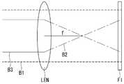
이하, 본 발명에 관련된 박막 평판형 수렴 렌즈에 대하여 상세히 설명한다. 도 3은 본 발명의 제1 실시 예에 의한 평행 직진광과 수렴광을 투명 기록 매질에 동시에 조사하여 간섭 패턴을 기록하는 방법을 도시한 도면이다. 도 4는 도 3에 의해 형성된 박막 평판형 수렴 렌즈에 의해 평행 직진광이 수렴되는 것을 보여주는 도면이다. 먼저, 도 3을 참조하여, 본 발명에 의한 박막 평판형 수렴 렌즈에 대한 기본 개념을 설명한다.Hereinafter, the thin film flat type converging lens according to the present invention will be described in detail. FIG. 3 is a diagram illustrating a method of recording an interference pattern by simultaneously irradiating a transparent recording medium with parallel straight beams and converging light according to the first embodiment of the present invention. FIG. 4 is a view showing parallel convergent light converged by the thin film flat type converging lens formed by FIG. 3; FIG. First, referring to FIG. 3, a basic concept of the thin film flat type converging lens according to the present invention will be described.
투명한 기록 매질이면서 동시에 박막 평판형 렌즈로 만들 평판 필름(FI)을 준비한다. 평판 필름(FI)의 일측면에서 제1 평행 직진광(B1)과 수렴광(B2)을 동시에 조사한다. 수렴광(B2)은 제2 평행 직진광(B3)을 볼록렌즈(LEN)에 조사하여 형성할 수 있다. 그러면, 평판 필름(FI)에는 평행 직진광(B1)과 수렴광(B2)이 중첩된 간섭 패턴이 기록된다. 이와 같이 간섭 패턴이 기록된 평판 필름(FI)이 바로 박막 평판형 수렴 렌즈(FL)가 된다.A flat film (FI) made of a transparent recording medium and made of a thin film flat type lens is prepared. The first parallel straight beam B1 and the converging light B2 are simultaneously irradiated on one side of the flat plate film FI. The converged light B2 can be formed by irradiating the convex lens LEN with the second parallel straight-line light B3. Then, an interference pattern in which the parallel linear light B1 and the convergent light B2 are superimposed is recorded in the flat plate film FI. The flat film FI on which the interference pattern is recorded becomes the thin film flat type converging lens FL.
도 4를 참조하여, 본 발명의 제1 실시 예에 의한 박막 평판형 수렴 렌즈를 통과하는 빛의 경로를 설명한다. 박막 평판형 수렴 렌즈(FL)의 일측면에서 평행 직진광(B1)을 조사하면, 평행 직진광(B1)은 박막 평판형 수렴 렌즈(FL)를 투과한 후에는 간섭 패턴에 의해 수렴광(B2)과 동일한 초점 f를 갖는 출사광(BO)으로 수렴된다.Referring to FIG. 4, the path of light passing through the thin film flat type converging lens according to the first embodiment of the present invention will be described. When parallel straight light B1 is irradiated from one side of the thin film flat type converging lens FL, the parallel straightbeam B1 is reflected by the convergent light B2 Converges to the outgoing light beam BO having the same f as the incident light beam.
그런데 본 발명의 실시 예1과 같은 방식으로 박막 평판형 수렴 렌즈(FL)를 형성하는 것은 실질적으로 불가능하다. 이유는 도 3에서와 같이 수렴광(B2)을 만들기 위한 렌즈(LEN)가 평행 직진광(B1)의 광 경로 상에 놓이게 되므로 제1 평행 직진광(B1)과 수렴광(B2)을 동시에 기록 매질인 평판 필름(FI)에 조사할 수 없다.However, it is practically impossible to form the thin film flat type converging lens FL in the same manner as the first embodiment of the present invention. Since the lens LEN for producing the converged light B2 is placed on the optical path of the parallel straightbeam B1 as shown in FIG. 3, the first parallel straightbeam B1 and the converged light B2 are simultaneously recorded It can not be irradiated to the flat film (FI) which is a medium.
이를 해결하기 위해, 본 발명에서는 실질적으로 제조할 수 있고, 사용할 수 있는 제2 실시 예를 제공한다. 도 5는 본 발명의 제2 실시 예에 의한 박막 평판형 수렴 렌즈(FL)의 구조를 나타내는 단면도이다.To solve this problem, the present invention provides a second embodiment which can be practically manufactured and used. 5 is a sectional view showing a structure of a thin film flat type converging lens FL according to a second embodiment of the present invention.
도 5를 참조하면, 제2 실시 예에 의한 박막 평판형 수렴 렌즈(FL)는 투명 기판(SUB)과, 상기 투명 기판(SUB)의 일측면에 부착된 필름 렌즈(PL)를 포함한다. 투명 기판(SUB)은 광학적으로 투명한 유리 혹은 투명 필름을 사용하는 것이 바람직하다. 더 바람직하게는 필름 렌즈(PL)의 재료와 굴절율이 동일한 투명 물질을 선택하는 것이 좋다.Referring to FIG. 5, the thin film flat type converging lens FL according to the second embodiment includes a transparent substrate SUB and a film lens PL attached to one side of the transparent substrate SUB. The transparent substrate SUB is preferably optically transparent glass or transparent film. More preferably, a transparent material having the same refractive index as the material of the film lens PL is selected.
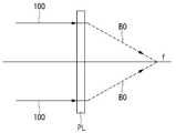
필름 렌즈(PL)는 입사각이 필름 렌즈(PL)의 평면으로 수직하게, 즉 광축에 대해서 0도의 입사각도를 갖는 평행 직진광(100)을 초점 f로 수렴하는 수렴광(BO)으로 전환하는 그레이팅 필름이다. 필름 렌즈(PL)는 500μm 이하의 두께를 갖는 광 반응성 필름인 것이 바람직하다. 또한, 광학적으로 투명한 광 반응성 고분자인 포토폴리머 (photopolymer) 혹은 젤라틴(gelatine)을 포함하는 물질로 형성하는 것이 바람직하다. 특히, 투명 기판(SUB)의 재료와 굴절율이 동일한 투명 물질을 선택하는 것이 좋다.The film lens PL is a grating for converting the parallel straight-
이하, 도 6a 및 6b를 참조하여, 필름 렌즈(PL)에 대하여 상세히 설명한다. 도 6a는 필름 렌즈(PL)를 형성하기 위한 마스터 필름(MP)을 제조하는 방법을 나타내는 개략도이다. 도 6b는 마스터 필름(MP)를 이용하여 필름 렌즈(PL)를 제조하는 방법을 나타내는 개략도이다.Hereinafter, the film lens PL will be described in detail with reference to Figs. 6A and 6B. 6A is a schematic view showing a method of manufacturing a master film MP for forming a film lens PL. 6B is a schematic view showing a method of manufacturing a film lens PL using a master film MP.
투명한 광 기록 매질이면서 박막 평판형 마스터 필름(MP)을 제조하기 위한 제1 평판 필름(FI1)을 준비한다. 제1 평판 필름(FI1)의 일측면에서 평행 직진광(100)과 경사 평행광(300)을 동시에 조사한다. 평행 직진광(100)은 광축에 대해 0도±5도의 범위 내의 각도로 입사하는 평행광인 것이 바람직하다. 경사 평행광(300)은 제1 평판 필름(FI1)의 일측면에서 광축에 대해 입사각도 θ도±5도의 범위 내의 각도를 갖고 평행하게 조사한다. 그러면, 제1 평판 필름(FI1)에는 평행 직진광(100)과 경사 평행광(300)이 중첩된 간섭 패턴이 기록된다. 이와 같이 간섭 패턴이 기록된 제1 평판 필름(FI1)이 바로 마스터 필름(MP)이 된다.A first flat film FI1 for producing a thin film flat master film (MP) having a transparent optical recording medium is prepared. Parallel
여기서, 경사 평행광(300)의 입사각도 θ는 도 3에서 설명한 바와 같이, 수렴광을 형성하기 위한 광학적 장치들에 간섭을 받지않고 제1 평판 필름(FI1)으로 입사할 수 있는 입사각도이어야 한다. 또한, 회절 효율이 최대 값을 가져야 한다. 여러 차례 실험한 결과, 경사 평행광(300)의 입사각도 θ는 상기 수선축에 대하여 45도 ± 30도 범위의 어느 한 값을 갖는 것이 바람직하다. 특히, 39도 내지 41도 범위 내에서 설계자의 선택에 의해서 적절한 값을 선택하는 것이 바람직하다. 실험 및 시뮬레이션 결과에 의하면, 39.2도 내지 40.2도 사이의 값이 바람직하며, 가장 바람직하게는 39.8도가 최적의 조건을 갖는다.Here, the angle of incidence? Of the oblique
그리고 나서, 마스터 필름(MP)을 이용하여, 필름 렌즈(PL)를 제조한다. 도 6b를 참조하여 마스터 필름(MP)에 경사 평행광(300)과 수렴광(450)을 이용하여 필름 렌즈(PL)를 제조하는 방법을 설명한다.Then, the film lens PL is manufactured using the master film MP. A method of manufacturing the film lens PL using the oblique
투명한 기록 매질이면서 동시에 필름 렌즈로 만들 제2 평판 필름(FI2)을 준비한다. 제2 평판 필름(FI2)의 일측면에 마스터 필름(MP)을 배치한다. 마스터 필름(FI2)에서 제2 평판 필름(FI2)이 놓인 방향의 반대면에서 수렴광(450)과 경사 평행광(300)을 동시에 조사한다.A second flat film FI2 to be a transparent recording medium and to be made into a film lens is prepared. A master film (MP) is disposed on one side of the second flat film (FI2). The
경사 평행광(300)은 마스터 필름(MP)의 일측면에서 광축에 대해 입사각도 θ인 45도 ± 30도 범위의 어느 한 값을 갖도록 평행하게 조사한다. 그러면, 경사 평행광(300)은 마스터 필름(MP)을 통과하면서, 마스터 필름(MP)에 형성된 간섭 무늬에 의해 회절되어, 평행 직진 출사광(350)으로 변하여 제2 평판 필름(FI2)으로 투사된다.The oblique
그리고 수렴광(450)은 제2 평행 직진광(400)을 볼록렌즈(LEN)에 조사하여 형성할 수 있다. 이때 수렴광(450)의 초점 f는 마스터 필름(MP)에서 수렴광(450)이 입사하는 면상에서 광축과 만나는 지점이 되도록 설정하는 것이 바람직하다. 이는, 수렴광(450)이 마스터 필름(MP)의 간섭 무늬에 의한 회절이 발생하지 않고 마스터 필름(MP)을 그대로 통과한다. 즉, 초점 f에서 발산하여 제2 평판 필름(FI2)으로 조사된다.The converging light 450 can be formed by irradiating the second parallel
그 결과, 제2 평판 필름(FI2)에는 수렴광(450)과 평행 직진 출사광(350)이 중첩된 간섭 무늬가 기록된다. 이와 같이 간섭 무늬가 기록된 제2 평판 필름(FI2)이 바로 필름 렌즈(PL)가 된다.As a result, interference fringes in which the converged
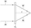
도 7a 및 도 7b를 참조하여, 본 발명의 제2 실시 예에 의해 제조한 필름 렌즈(PL)를 통과하는 빛의 경로를 설명함으로써 필름 렌즈의 작동에 대하여 설명한다. 도 7a는 필름 렌즈를 이용하여 평행 직진광이 수렴광으로 바꾸는 과정을 보여주는 광 경로를 나타내는 도면이다. 도 7b는 필름 렌즈를 이용하여 발산광이 평행 직진광으로 바꾸는 과정을 보여주는 광 경로를 나타내는 도면이다.7A and 7B, the operation of the film lens will be described by explaining the path of light passing through the film lens PL manufactured by the second embodiment of the present invention. FIG. 7A is a view showing a light path showing a process of converting parallel straight-line light into converged light using a film lens. FIG. 7B is a view showing a light path showing a process of converting divergent light into parallel straight light using a film lens.
본 발명의 제2 실시 예에 의한 필름 렌즈(PL)의 일측면에서 평행 직진광(100)을 조사하면, 도 7a에 도시한 바와 같이, 필름 렌즈(PL)에 형성된 회절 무늬를 통과한 후에는 초점 f로 수렴하는 수렴광(BO)으로 출사한다. 반면에, 필름 렌즈(PL)의 일측면에서 초점 f를 갖는 발산광(455)을 조사하면, 도 7b에 도시한 바와 같이, 필름 렌즈(PL)에 형성된 회절 무늬를 통과한 후에는 광축에 대해서 평행한 직진 평행광(150)으로 출사한다.When the parallel
이상 본 발명의 제2 실시 예에 의한 박막 평판형 수렴 렌즈(FL)는 홀로그래피 방식의 입체 영상 표시장치에 적용할 수 있다. 도 8은 본 발명의 제2 실시 예에 의해 제조한 박막 평판형 수렴 렌즈(FL)를 구비한 홀로그래피 방식의 입체 영상 표시장치에서 입체 영상이 관람자의 눈에 초점이 설정된 상태를 나타낸 개략도이다. 도 8을 참조하면, 백 라이트 유닛(BLU)을 출사한 백 라이트(BL)는 공간 광 변조기(200)에 의해 홀로그램에 의한 입체 영상을 구현한다. 입체 영상은 박막 평판형 수렴 렌즈(FL)에 의해 관람자의 눈으로 전송된다. 특히, 관람자의 눈에 입체 영상의 초점이 맞추어져 수렴하므로, 정확한 입체 영상을 관람자에게 제공할 수 있다.The thin film flat type converging lens FL according to the second embodiment of the present invention can be applied to a holographic stereoscopic image display device. FIG. 8 is a schematic view showing a state in which a stereoscopic image is focused on a spectator's eye in a holographic stereoscopic image display device having a thin flat plate type converging lens FL manufactured by a second embodiment of the present invention. Referring to FIG. 8, a backlight BL that has emitted a backlight unit (BLU) implements a stereoscopic image by a hologram by a spatial light modulator (200). The stereoscopic image is transmitted to the eye of the spectator by the thin film flat converging lens (FL). Particularly, since the stereoscopic image is focused on the spectator's eye and converged, an accurate stereoscopic image can be provided to the spectator.
이상 설명한 내용을 통해 당업자라면 본 발명의 기술 사상을 일탈하지 아니하는 범위에서 다양한 변경 및 수정이 가능함을 알 수 있을 것이다. 따라서, 본 발명의 기술적 범위는 명세서의 상세한 설명에 기재된 내용으로 한정되는 것이 아니라 특허 청구의 범위에 의해 정해져야만 할 것이다.It will be apparent to those skilled in the art that various modifications and variations can be made in the present invention without departing from the spirit or scope of the invention. Therefore, the technical scope of the present invention should not be limited to the contents described in the detailed description of the specification, but should be defined by the claims.
10: 컴퓨터20, 200: SLM(공간 광 변조기)
30, 300: 레이저 광원40: 확장기
50: 렌즈80: 출력 영상
90: 참조광500: 광학 시트
SU: 상판SD: 하판
LC: 액정층R: 적색 레이저 다이오드
G: 녹색 레이저 다이오드B: 청색 레이저 다이오드
OF: 광섬유BLU: 백 라이트 유닛
OUT: 광 출사부IN: 광 입사부
500: 광학 필름ET: 아이 트래커
FL: 박막 평판형 수렴 렌즈
B1: 제1 평행 직진광B2, 450: 수렴광
B3, 400: 제2 평행 직진광LEN: 볼록 렌즈
FI: 평판 필름FI1: 제1 평판 필름
FI2: 제2 평판 필름MP: 마스터 필름
PL: 필름 렌즈SUB: 투명 기판
BO: 출사광100: 평행 직진광
300: 경사 직진광350: 평행 직진 출사광
150: 직진 평행광10:
30, 300: laser light source 40: expander
50: Lens 80: Output image
90: reference light 500: optical sheet
SU: top plate SD: bottom plate
LC: liquid crystal layer R: red laser diode
G: green laser diode B: blue laser diode
OF: Fiber optic BLU: Backlight unit
OUT: light output portion IN: light input portion
500: Optical film ET: Eye Tracker
FL: Thin film flat type convergent lens
B1: first parallel straightbeam B2, 450: converging light
B3, 400: second parallel straight light LEN: convex lens
FI: Flat film FI1: First flat film
FI2: second flat film MP: master film
PL: Film lens SUB: Transparent substrate
BO: outgoing light 100: parallel straight light
300: Straight incline light 350: Straight parallel light
150: straight parallel light
Claims (8)
Translated fromKorean상기 백 라이트 유닛의 일면에 배치된 박막형 공간 광 조절기; 그리고
상기 박막형 공간 광 조절기의 일면에 배치된 투명 기판, 및 상기 투명 기판의 일측면에 부착되며, 일측변에서 상기 투명 기판의 수선축에 대해 평행하게 입사되는 평행 직진광을 수렴광으로 변환하여 타측변으로 출사하는 간섭 무늬가 투명 필름에 형성된 필름 렌즈를 구비하는 박막 평판형 수렴 렌즈를 포함하되,
상기 간섭 무늬는,
상기 투명 기판의 수선축에 대해 경사각도를 갖고 입사하는 경사 직진광을 상기 평행 직진광으로 변환하는 간섭 패턴을 갖는 마스터 필름의 일측변에서, 상기 마스터 필름으로 상기 경사 직진광과 상기 수렴광을 동시에 조사하여, 상기 마스터 필름에 의해 변환된 상기 평행 직진광과 상기 마스터 필름을 통과한 상기 수렴광을 중첩하여 형성된 것이며,
상기 수렴광은,
상기 마스터 필름의 상기 일측변에서 상기 수선축에 평행하게 입사되는 상기 평행 직진광이, 상기 수선축 위에서 그리고 상기 마스터 필름의 광 입사면 위에 초점이 설정된 볼록 렌즈를 통하여 출사되는 것을 특징으로 하는 입체 영상 표시장치.
A backlight unit for providing a backlight;
A thin-film spatial light modulator disposed on one surface of the backlight unit; And
A spatial light modulator disposed on one side of the thin-film spatial light modulator, and a plurality of parallel light beams, which are attached to one side of the transparent substrate and convert parallel straight-line light incident parallel to the water- And a thin film flat type convergent lens having a film lens in which an interference fringe emerging from the thin film is formed on a transparent film,
The interference fringe,
And the convergent light is converged to the master film at one side of the master film having an interference pattern that has an inclination angle with respect to the water-repellent axis of the transparent substrate and converts an incident linear light into the parallel straight- And superimposing the parallel straight-line light converted by the master film and the convergent light passing through the master film,
The convergent light,
Wherein the parallel straight-line light incident on the one side of the master film in parallel to the water-repellent axis is emitted through a convex lens focused on the water-repellent axis and on the light-incident surface of the master film. Display device.
상기 경사 직진광은, 상기 경사 각도가 상기 수선축에 대하여 45도 ± 30도 범위의 어느 한 값을 갖는 것을 특징으로 하는 입체 영상 표시장치.
The method according to claim 1,
Wherein the obliquely advancing light has an inclination angle which is a value within a range of 45 degrees +/- 30 degrees with respect to the waterline axis.
상기 필름 렌즈는 500μm 이하의 두께를 갖는 광반응 특성을 갖는 필름을 포함하는 것을 특징으로 하는 입체 영상 표시장치.
The method according to claim 1,
Wherein the film lens comprises a film having a photoreaction characteristic with a thickness of 500 mu m or less.
상기 필름 렌즈는, 투명한 포토폴리머 (photopolymer) 및 투명한 젤라틴(gelatine) 중 적어도 어느 하나를 포함하는 것을 특징으로 하는 입체 영상 표시장치.
The method according to claim 1,
Wherein the film lens comprises at least one of a transparent photopolymer and a transparent gelatin.
상기 투명 기판 그리고 상기 필름 렌즈는 굴절율이 동일한 것을 특징으로 하는 입체 영상 표시장치.The method according to claim 1,
Wherein the transparent substrate and the film lens have the same refractive index.
Priority Applications (3)
| Application Number | Priority Date | Filing Date | Title |
|---|---|---|---|
| KR1020110119190AKR101524336B1 (en) | 2011-11-15 | 2011-11-15 | Thin Flat Type Converge Lens |
| CN201210460134.2ACN103105634B (en) | 2011-11-15 | 2012-11-15 | Thin flat type convergence lens |
| US13/678,232US20130120816A1 (en) | 2011-11-15 | 2012-11-15 | Thin flat type convergence lens |
Applications Claiming Priority (1)
| Application Number | Priority Date | Filing Date | Title |
|---|---|---|---|
| KR1020110119190AKR101524336B1 (en) | 2011-11-15 | 2011-11-15 | Thin Flat Type Converge Lens |
Publications (2)
| Publication Number | Publication Date |
|---|---|
| KR20130053656A KR20130053656A (en) | 2013-05-24 |
| KR101524336B1true KR101524336B1 (en) | 2015-06-11 |
Family
ID=48280378
Family Applications (1)
| Application Number | Title | Priority Date | Filing Date |
|---|---|---|---|
| KR1020110119190AExpired - Fee RelatedKR101524336B1 (en) | 2011-11-15 | 2011-11-15 | Thin Flat Type Converge Lens |
Country Status (3)
| Country | Link |
|---|---|
| US (1) | US20130120816A1 (en) |
| KR (1) | KR101524336B1 (en) |
| CN (1) | CN103105634B (en) |
Families Citing this family (9)
| Publication number | Priority date | Publication date | Assignee | Title |
|---|---|---|---|---|
| CN103402111B (en)* | 2013-08-13 | 2015-04-08 | 宁波维真显示科技有限公司 | Big-sized 2D-3D switching display device |
| CN110376743B (en) | 2014-01-31 | 2022-03-04 | 奇跃公司 | Multi-focus display system and method |
| US9612687B2 (en)* | 2014-07-01 | 2017-04-04 | Microsoft Technology Licensing, Llc | Auto-aligned illumination for interactive sensing in retro-reflective imaging applications |
| KR102294293B1 (en)* | 2014-09-29 | 2021-08-27 | 엘지디스플레이 주식회사 | Thin Flat Type Controlled Viewing Window Display Using The Same |
| KR101648895B1 (en) | 2014-10-28 | 2016-08-17 | 한국표준과학연구원 | Residue free transfer method of graphene/metal samples pasted by limited polymer line |
| KR20180066166A (en) | 2015-10-05 | 2018-06-18 | 매직 립, 인코포레이티드 | Microlens collimator for scanning optical fiber in virtual / augmented reality system |
| AU2016336546B2 (en)* | 2015-10-06 | 2021-09-16 | Magic Leap, Inc. | Virtual/augmented reality system having reverse angle diffraction grating |
| CN113406801B (en) | 2016-01-20 | 2023-05-30 | 奇跃公司 | Polarization-Maintaining Optical Fibers in Virtual/Augmented Reality Systems |
| US12019253B2 (en) | 2022-09-30 | 2024-06-25 | Universal City Studios Llc | Oscillating stacked digital displays for holographic image |
Citations (2)
| Publication number | Priority date | Publication date | Assignee | Title |
|---|---|---|---|---|
| US4393126A (en)* | 1980-05-14 | 1983-07-12 | Sony Corporation | Method for manufacturing in-line hologram lens |
| JP2002162601A (en)* | 2000-11-27 | 2002-06-07 | Noritsu Koki Co Ltd | Specific viewpoint image display device and multi viewpoint image display device |
Family Cites Families (6)
| Publication number | Priority date | Publication date | Assignee | Title |
|---|---|---|---|---|
| US6075579A (en)* | 1995-11-30 | 2000-06-13 | Dai Nippon Printing Co., Ltd. | Liquid crystal display device using a hologram, hologram scatter plate, and process of replicating a diffuse reflection type hologram |
| JPH11242443A (en)* | 1997-10-15 | 1999-09-07 | Kyowa Electric & Chem Co Ltd | Image enlarging observation system and filter assembly for the system |
| CN2616916Y (en)* | 2003-01-27 | 2004-05-19 | 中国科学院上海光学精密机械研究所 | photorefractive flat lens |
| WO2005099386A2 (en)* | 2004-04-13 | 2005-10-27 | Board Of Regents, The University Of Texas System | Holographic projector |
| TWI345105B (en)* | 2006-01-26 | 2011-07-11 | Chimei Innolux Corp | Backlight module and application thereof |
| GB2461294B (en)* | 2008-06-26 | 2011-04-06 | Light Blue Optics Ltd | Holographic image display systems |
- 2011
- 2011-11-15KRKR1020110119190Apatent/KR101524336B1/ennot_activeExpired - Fee Related
- 2012
- 2012-11-15CNCN201210460134.2Apatent/CN103105634B/ennot_activeExpired - Fee Related
- 2012-11-15USUS13/678,232patent/US20130120816A1/ennot_activeAbandoned
Patent Citations (2)
| Publication number | Priority date | Publication date | Assignee | Title |
|---|---|---|---|---|
| US4393126A (en)* | 1980-05-14 | 1983-07-12 | Sony Corporation | Method for manufacturing in-line hologram lens |
| JP2002162601A (en)* | 2000-11-27 | 2002-06-07 | Noritsu Koki Co Ltd | Specific viewpoint image display device and multi viewpoint image display device |
Also Published As
| Publication number | Publication date |
|---|---|
| US20130120816A1 (en) | 2013-05-16 |
| KR20130053656A (en) | 2013-05-24 |
| CN103105634B (en) | 2015-03-11 |
| CN103105634A (en) | 2013-05-15 |
Similar Documents
| Publication | Publication Date | Title |
|---|---|---|
| KR101524336B1 (en) | Thin Flat Type Converge Lens | |
| US11953856B2 (en) | Holographic display apparatus | |
| JP7387805B2 (en) | Method and system for generating virtual content displays using virtual or augmented reality devices | |
| KR101507202B1 (en) | Spatial Light Modulating Panel Using Transparent Type Liquid Crystal Display Panel And 3D Display Device Using The Same | |
| Lee et al. | Additive light field displays: realization of augmented reality with holographic optical elements | |
| US8817068B2 (en) | Digital hologram image display device | |
| JP4133832B2 (en) | Color video holography playback device | |
| CN103108207B (en) | Dual holography 3D display device | |
| US20120050830A1 (en) | Digital hologram image display device | |
| KR101495401B1 (en) | Back Light Unit Providing Direction Controllable Collimated Light Beam And 3D Display Using The Same | |
| JP2002040911A (en) | Image reproducing device and image reproducing method | |
| KR102013379B1 (en) | Multi-View Holography 3D Display Device | |
| KR20130106723A (en) | Spatial light modulator using transparent type liquid crystal display panel based on thin film and 3d display device using the same | |
| KR102040657B1 (en) | Spatial Light Modulating Panel And Holography 3D Display Using The Same | |
| KR102099142B1 (en) | Spatial Light Modulating Panel and 3D Display Device Using The same | |
| KR101980353B1 (en) | Thin Flat Type Converge Lens | |
| KR20130011421A (en) | Holographic 3d display | |
| KR101855258B1 (en) | Dynamic Thin Flat Type Light-Beam Deflector | |
| JP2023008330A (en) | Holography reproduction illumination light irradiation device and holographic display | |
| Jeon et al. | Perspective distortion correction in a compact, full-color holographic stereogram printer | |
| JP7547583B2 (en) | Holographic recording method and device | |
| CN109031916A (en) | A kind of holographic display and method | |
| US20220004148A1 (en) | Apparatus and method of reproduction of a diffractive pattern |
Legal Events
| Date | Code | Title | Description |
|---|---|---|---|
| PA0109 | Patent application | St.27 status event code:A-0-1-A10-A12-nap-PA0109 | |
| R18-X000 | Changes to party contact information recorded | St.27 status event code:A-3-3-R10-R18-oth-X000 | |
| PG1501 | Laying open of application | St.27 status event code:A-1-1-Q10-Q12-nap-PG1501 | |
| A201 | Request for examination | ||
| PA0201 | Request for examination | St.27 status event code:A-1-2-D10-D11-exm-PA0201 | |
| D13-X000 | Search requested | St.27 status event code:A-1-2-D10-D13-srh-X000 | |
| D14-X000 | Search report completed | St.27 status event code:A-1-2-D10-D14-srh-X000 | |
| E902 | Notification of reason for refusal | ||
| PE0902 | Notice of grounds for rejection | St.27 status event code:A-1-2-D10-D21-exm-PE0902 | |
| T11-X000 | Administrative time limit extension requested | St.27 status event code:U-3-3-T10-T11-oth-X000 | |
| T11-X000 | Administrative time limit extension requested | St.27 status event code:U-3-3-T10-T11-oth-X000 | |
| E13-X000 | Pre-grant limitation requested | St.27 status event code:A-2-3-E10-E13-lim-X000 | |
| P11-X000 | Amendment of application requested | St.27 status event code:A-2-2-P10-P11-nap-X000 | |
| P13-X000 | Application amended | St.27 status event code:A-2-2-P10-P13-nap-X000 | |
| E90F | Notification of reason for final refusal | ||
| PE0902 | Notice of grounds for rejection | St.27 status event code:A-1-2-D10-D21-exm-PE0902 | |
| T11-X000 | Administrative time limit extension requested | St.27 status event code:U-3-3-T10-T11-oth-X000 | |
| P11-X000 | Amendment of application requested | St.27 status event code:A-2-2-P10-P11-nap-X000 | |
| P13-X000 | Application amended | St.27 status event code:A-2-2-P10-P13-nap-X000 | |
| E701 | Decision to grant or registration of patent right | ||
| PE0701 | Decision of registration | St.27 status event code:A-1-2-D10-D22-exm-PE0701 | |
| GRNT | Written decision to grant | ||
| PR0701 | Registration of establishment | St.27 status event code:A-2-4-F10-F11-exm-PR0701 | |
| PR1002 | Payment of registration fee | St.27 status event code:A-2-2-U10-U11-oth-PR1002 Fee payment year number:1 | |
| PG1601 | Publication of registration | St.27 status event code:A-4-4-Q10-Q13-nap-PG1601 | |
| FPAY | Annual fee payment | Payment date:20180416 Year of fee payment:4 | |
| PR1001 | Payment of annual fee | St.27 status event code:A-4-4-U10-U11-oth-PR1001 Fee payment year number:4 | |
| FPAY | Annual fee payment | Payment date:20190417 Year of fee payment:5 | |
| PR1001 | Payment of annual fee | St.27 status event code:A-4-4-U10-U11-oth-PR1001 Fee payment year number:5 | |
| P22-X000 | Classification modified | St.27 status event code:A-4-4-P10-P22-nap-X000 | |
| P22-X000 | Classification modified | St.27 status event code:A-4-4-P10-P22-nap-X000 | |
| PR1001 | Payment of annual fee | St.27 status event code:A-4-4-U10-U11-oth-PR1001 Fee payment year number:6 | |
| PR1001 | Payment of annual fee | St.27 status event code:A-4-4-U10-U11-oth-PR1001 Fee payment year number:7 | |
| PR1001 | Payment of annual fee | St.27 status event code:A-4-4-U10-U11-oth-PR1001 Fee payment year number:8 | |
| PC1903 | Unpaid annual fee | St.27 status event code:A-4-4-U10-U13-oth-PC1903 Not in force date:20230523 Payment event data comment text:Termination Category : DEFAULT_OF_REGISTRATION_FEE | |
| PC1903 | Unpaid annual fee | St.27 status event code:N-4-6-H10-H13-oth-PC1903 Ip right cessation event data comment text:Termination Category : DEFAULT_OF_REGISTRATION_FEE Not in force date:20230523 |