KR101524285B1 - Apparatus and method for timing synchronization in communication system - Google Patents
Apparatus and method for timing synchronization in communication systemDownload PDFInfo
- Publication number
- KR101524285B1 KR101524285B1KR1020090007898AKR20090007898AKR101524285B1KR 101524285 B1KR101524285 B1KR 101524285B1KR 1020090007898 AKR1020090007898 AKR 1020090007898AKR 20090007898 AKR20090007898 AKR 20090007898AKR 101524285 B1KR101524285 B1KR 101524285B1
- Authority
- KR
- South Korea
- Prior art keywords
- clock
- phase
- minimum value
- node
- reference range
- Prior art date
- Legal status (The legal status is an assumption and is not a legal conclusion. Google has not performed a legal analysis and makes no representation as to the accuracy of the status listed.)
- Expired - Fee Related
Links
Images


Classifications
- H—ELECTRICITY
- H04—ELECTRIC COMMUNICATION TECHNIQUE
- H04L—TRANSMISSION OF DIGITAL INFORMATION, e.g. TELEGRAPHIC COMMUNICATION
- H04L7/00—Arrangements for synchronising receiver with transmitter
- H04L7/04—Speed or phase control by synchronisation signals
- H04L7/10—Arrangements for initial synchronisation
- H—ELECTRICITY
- H04—ELECTRIC COMMUNICATION TECHNIQUE
- H04J—MULTIPLEX COMMUNICATION
- H04J3/00—Time-division multiplex systems
- H04J3/02—Details
- H04J3/06—Synchronising arrangements
- H04J3/0635—Clock or time synchronisation in a network
- H04J3/0638—Clock or time synchronisation among nodes; Internode synchronisation
- H04J3/0644—External master-clock
- H—ELECTRICITY
- H04—ELECTRIC COMMUNICATION TECHNIQUE
- H04J—MULTIPLEX COMMUNICATION
- H04J3/00—Time-division multiplex systems
- H04J3/02—Details
- H04J3/06—Synchronising arrangements
- H04J3/0635—Clock or time synchronisation in a network
- H04J3/0682—Clock or time synchronisation in a network by delay compensation, e.g. by compensation of propagation delay or variations thereof, by ranging
- H—ELECTRICITY
- H04—ELECTRIC COMMUNICATION TECHNIQUE
- H04L—TRANSMISSION OF DIGITAL INFORMATION, e.g. TELEGRAPHIC COMMUNICATION
- H04L43/00—Arrangements for monitoring or testing data switching networks
- H04L43/08—Monitoring or testing based on specific metrics, e.g. QoS, energy consumption or environmental parameters
- H04L43/0852—Delays
- H—ELECTRICITY
- H04—ELECTRIC COMMUNICATION TECHNIQUE
- H04L—TRANSMISSION OF DIGITAL INFORMATION, e.g. TELEGRAPHIC COMMUNICATION
- H04L7/00—Arrangements for synchronising receiver with transmitter
- H04L7/02—Speed or phase control by the received code signals, the signals containing no special synchronisation information
Landscapes
- Engineering & Computer Science (AREA)
- Computer Networks & Wireless Communication (AREA)
- Signal Processing (AREA)
- Environmental & Geological Engineering (AREA)
- Synchronisation In Digital Transmission Systems (AREA)
Abstract
Translated fromKoreanDescription
Translated fromKorean본 발명은 통신시스템에서 노드 간에 시간 동기화를 수행하기 위한 장치 및 방법에 관한 것으로서, 특히 통신시스템에서 GPS(Global Positioning System) 동기 신호를 수신받지 못하는 노드들의 시간을 동기화하는 장치 및 방법에 관한 것이다.BACKGROUND OF THE
통신 시스템을 구성하는 노드가 GPS 신호를 수신받을 수 있는 경우, 상기 노드는 GPS 위성으로부터 제공받은 GPS 동기 신호를 통해 획득한 주파수 동기 및 시간 동기에 따라 클럭을 복원 및 생성한다. 여기서, GPS 신호를 수신받을 수 있는 노드를 마스터 노드라 칭한다.When the node configuring the communication system can receive the GPS signal, the node recovers and generates the clock according to the frequency synchronization and the time synchronization acquired through the GPS synchronization signal provided from the GPS satellite. Here, a node capable of receiving a GPS signal is called a master node.
한편, 통신 시스템을 구성하는 노드가 GPS 신호를 수신받지 못하는 경우, 상기 노드는 상기 마스터 노드로부터 제공받은 동기 정보를 통해 획득한 주파수 동기 및 시간 동기에 따라 클럭을 복원 및 생성한다. 여기서, GPS 신호를 수신받을 수 없는 노드를 슬레이브 노드라 칭한다.On the other hand, when the node constituting the communication system does not receive the GPS signal, the node recovers and generates the clock according to the frequency synchronization and the time synchronization acquired through the synchronization information provided from the master node. Here, a node that can not receive the GPS signal is called a slave node.
이때, 마스터 노드는 패킷을 통해 슬레이브 노드로 동기 정보를 전송한다. 이에 따라, 트래픽 부하가 증가하는 경우, 슬레이브 노드는 동기 정보를 포함하는 패킷의 전송지연으로 인해 하기 도 1에 도시된 바와 같이 위상 점프(phase jump) 현상이 발생한다.At this time, the master node transmits synchronization information to the slave node through the packet. Accordingly, when the traffic load increases, a phase jump phenomenon occurs in the slave node as shown in FIG. 1 due to the transmission delay of the packet including the synchronization information.
도 1은 종래 기술에 따른 통신시스템에서 트래픽 부하에 따른 클럭의 위상 변화그래프를 도시하고 있다.FIG. 1 is a graph illustrating a phase change of a clock according to a traffic load in a communication system according to the related art.
상기 도 1에 도시된 바와 같이 트래픽 부가(100)가 순간적으로 증가하는 경우, 슬레이브 노드는 동기 정보를 포함하는 패킷의 전송지연으로 인해 클럭의 위상(110)이 점프하는 문제가 발생한다.As shown in FIG. 1, when the traffic addition unit 100 instantaneously increases, the slave node has a problem that the phase 110 of the clock jumps due to the transmission delay of the packet including the synchronization information.
또한, 슬레이브 노드는 네트워크 경로의 물리적, 시간적 차이에 의한 위상 차로 인해 위상 동기에 대해 위상 점프 또는 위상 이탈(deviation)이 크게 발생하는 문제가 있다.In addition, the slave node has a problem that a phase jump or a deviation deviates greatly from the phase synchronization due to the phase difference due to the physical and temporal difference of the network path.
따라서, 본 발명의 목적은 통신시스템에서 GPS(Global Positioning System) 동기 신호를 수신받지 못하는 노드의 클럭 복원 장치 및 방법을 제공함에 있다.SUMMARY OF THE INVENTION Accordingly, it is an object of the present invention to provide an apparatus and method for recovering a clock of a node that does not receive a Global Positioning System (GPS) synchronization signal in a communication system.
본 발명의 다른 목적은 인빌딩(In building) 시스템에서 GPS 동기 신호를 수신받지 못하는 노드의 시간 동기화 장치 및 방법을 제공함에 있다.It is another object of the present invention to provide a time synchronization apparatus and method for a node that does not receive a GPS synchronization signal in an in building system.
본 발명의 또 다른 목적은 통신시스템에서 트래픽 부하의 변화로 인한 위상 이탈 값의 변화를 개선하여 GPS 동기 신호를 수신받지 못하는 노드의 시간을 동기화하는 장치 및 방법을 제공함에 있다.It is still another object of the present invention to provide an apparatus and method for synchronizing time of a node that does not receive a GPS synchronous signal by improving a change in a phase shift value due to a change in traffic load in a communication system.
본 발명의 또 다른 목적은 통신시스템에서 GPS 동기 신호를 수신받지 못하는 노드의 클럭 복원 시 협정 세계시(UTC: Universal Time Coordinated)와의 오프셋을 최소로 설정하기 위한 장치 및 방법을 제공함에 있다.It is still another object of the present invention to provide an apparatus and method for minimizing an offset from Universal Time Coordinated (UTC) in clock recovery of a node that does not receive a GPS synchronous signal in a communication system.
본 발명의 목적들을 달성하기 위한 본 발명의 제 1 견지에 따르면, 대칭적으로 구성된 네트워크를 포함하는 통신시스템에서 GPS(Global Positioning System) 신호를 수신받지 못하는 노드의 클럭 복원 방법은, GPS 신호를 수신받을 수 있는 제 1 노드로부터 제공받은 동기 정보를 확인하는 과정과, 상기 제 1 노드와의 지연을 확인하는 과정과, 상기 동기 정보와 지연을 이용하여 클럭을 생성하는 과정과, 기준 범위를 넘는 클럭의 위상을 제거하는 과정과, 기준 범위를 넘는 클럭의 위상 을 제거한 클럭을 출력하는 과정을 포함하는 것을 특징으로 한다.According to a first aspect of the present invention, there is provided a method of restoring a clock of a node that does not receive a Global Positioning System (GPS) signal in a communication system including a symmetrically configured network, The method comprising the steps of: confirming synchronization information provided from a first node capable of receiving a clock signal; confirming a delay with the first node; generating a clock using the synchronization information and the delay; And a step of outputting a clock from which the phases of the clocks exceeding the reference range are removed.
본 발명의 제 2 견지에 따르면, 대칭적으로 구성된 네트워크를 포함하는 통신시스템에서 GPS 신호를 수신받지 못하는 노드의 클럭 복원 장치는, GPS 신호를 수신받을 수 있는 제 1 노드와 신호를 송수신하는 송수신 인터페이스와, 상기 제 1 노드와의 지연을 확인하는 지연 확인부와, 상기 송수신 인터페이스를 통해 상기 제 1 노드로부터 제공받은 동기 정보와 상기 지연 확인부에서 확인한 지연을 이용하여 클럭을 생성하는 클럭 발생부와, 상기 클럭 발생부에서 생성한 클럭에서 기준 범위를 넘는 클럭의 위상을 제거하여 출력하는 클럭 보정부를 포함하여 구성되는 것을 특징으로 한다.According to a second aspect of the present invention, in a communication system including a symmetrically configured network, a clock recovery apparatus for a node that does not receive a GPS signal includes a transmission / reception interface A clock generation unit for generating a clock using the synchronization information provided from the first node through the transmission / reception interface and the delay determined by the delay confirmation unit; And a clock correcting unit for removing a phase of a clock signal exceeding a reference range from the clock signal generated by the clock generating unit and outputting the removed clock signal.
상술한 바와 같이 통신 시스템의 GPS 신호를 수신받지 못하는 노드에서 트래픽 부하의 변화로 인한 위상 이탈 값의 변화를 개선하여 클럭을 복원 및 생성함으로써, 시간 동기화를 이룰 수 있고, 인 빌딩(In-building) 시스템에서 IP망을 통한 저가의 안정적인 동기를 구현할 수 있는 이점이 있다.As described above, time synchronization can be achieved by restoring and generating a clock by improving a change in a phase shift value due to a change in a traffic load at a node not receiving a GPS signal of the communication system, The system has an advantage that low-cost and stable synchronization can be realized through the IP network.
이하 본 발명의 바람직한 실시 예를 첨부된 도면을 참조하여 상세히 설명한다. 그리고, 본 발명을 설명함에 있어서, 관련된 공지기능 혹은 구성에 대한 구체적인 설명이 본 발명의 요지를 불필요하게 흐릴 수 있다고 판단된 경우 그 상세한 설명은 생략한다. 그리고 후술되는 용어들은 본 발명에서의 기능을 고려하여 정의된 용어들로서 이는 사용자, 운용자의 의도 또는 관례 등에 따라 달라질 수 있다. 그러므로 그 정의는 본 명세서 전반에 걸친 내용을 토대로 내려져야 할 것이다.Hereinafter, preferred embodiments of the present invention will be described in detail with reference to the accompanying drawings. In the following description, a detailed description of known functions and configurations incorporated herein will be omitted when it may make the subject matter of the present invention rather unclear. The following terms are defined in consideration of the functions of the present invention, and these may be changed according to the intention of the user, the operator, or the like. Therefore, the definition should be based on the contents throughout this specification.
이하 본 발명은 통신시스템에서 GPS(Global Positioning System) 동기 신호를 수신받지 못하는 노드의 클럭 복원 기술에 대해 설명한다.Hereinafter, a clock recovery technique of a node that does not receive a global positioning system (GPS) synchronization signal in a communication system will be described.
이하 설명에서 통신시스템은 슬레이브 노드의 시간 동기화를 위해 하기 도 2에 도시된 바와 같이 대칭(symmetric)적인 네트워크를 구성해야 한다. 여기서, 상기 슬레이브 노드는 GPS 신호를 수신받지 못해 마스터 노드로부터 제공받은 동기 정보에 따라 클럭을 복원 및 생성하는 노드를 의미한다. 또한, 상기 마스터 노드는 GPS(Global Positioning System) 신호를 수신받는 노드를 의미한다.In the following description, the communication system should configure a symmetric network as shown in FIG. 2 for time synchronization of slave nodes. Here, the slave node refers to a node that does not receive the GPS signal and restores and generates the clock according to the synchronization information provided from the master node. Also, the master node means a node receiving a Global Positioning System (GPS) signal.
도 2는 본 발명에 따른 통신시스템의 구성을 도시하고 있다.2 shows a configuration of a communication system according to the present invention.
상기 도 2에 도시된 바와 같이 통신시스템은 마스터 노드(200), L2 스위치(210-1, 210-2), 라우터(220-1, 220-2) 및 슬레이브 노드(230, 240, 250)를 포함하여 구성된다.2, the communication system includes a master node 200, L2 switches 210-1 and 210-2, routers 220-1 and 220-2, and
이때, 통신 시스템은 마스터 노드(200)와 슬레이브 노드들(230, 240, 250)들의 송수시 패킷 지연에 대한 오차를 최소화하기 위해 네트워크를 대칭되도록 구성한다.At this time, the communication system configures the network to be symmetrical in order to minimize the error of the packet delay when the master node 200 and the
상술한 바와 같이 네트워크가 대칭적으로 구성된 경우, 슬레이브 노드는 하기 도 3에 도시된 바와 같이 주파수/시간을 동기화한다.When the network is configured symmetrically as described above, the slave node synchronizes the frequency / time as shown in Fig.
도 3은 본 발명의 실시 예에 따른 통신시스템에서 클럭을 복원하기 위한 절 차를 도시하고 있다.FIG. 3 illustrates a procedure for recovering a clock in a communication system according to an embodiment of the present invention.
상기 도 3을 참조하면 슬레이브 노드는 301단계에서 마스터 노드로부터 동기 정보를 포함하는 패킷을 수신받는다.Referring to FIG. 3, in
마스터 노드로부터 동기 정보를 포함하는 패킷을 수신받은 후, 상기 슬레이브 노드는 303단계로 진행하여 상기 마스터 노드와의 지연(delay)을 확인한다. 예를 들어, 슬레이브 노드는 동기 정보를 포함하는 패킷을 수신받은 시점 정보를 포함하는 지연 요청 메시지를 상기 마스터 노드로 전송한다. 상기 마스터 노드는 상기 지연 요청 메시지에 대한 응답 메시지를 상기 슬레이브 노드로 전송한다. 이때, 상기 응답 메시지는 상기 지연 요청 메시지를 수신받은 시점과 상기 응답 메시지를 전송하는 시점 정보를 포함한다.After receiving the packet including the synchronization information from the master node, the slave node proceeds to
이에 따라, 상기 슬레이브 노드는 상기 마스터 노드로부터 제공받은 응답 메시지를 통해 상기 마스터 노드와의 지연을 확인할 수 있다.Accordingly, the slave node can confirm the delay with the master node through the response message provided from the master node.
이후, 상기 슬레이브 노드는 305단계로 진행하여 상기 301단계에서 제공받은 동기 정보와 상기 303단계에서 확인한 지연 정보를 이용하여 확인한 주파수 동기와 타이밍 동기에 따라 클럭을 생성한다.Thereafter, the slave node proceeds to step 305 and generates a clock according to the frequency synchronization and the timing synchronization, which are determined using the synchronization information provided in
상기 클럭을 생성한 후, 상기 슬레이브 노드는 307단계로 진행하여 위상 확인 구간을 변경한다. 즉, 상기 슬레이브 노드는 위상 확인 구간을 증가시킨다.After generating the clock, the slave node proceeds to
상기 위상 확인 구간을 증가시킨 후, 상기 슬레이브 노드는 309단계로 진행하여 위상 확인 구간에 포함되는 클럭의 위상을 확인한다.After incrementing the phase checking interval, the slave node proceeds to
이후, 상기 슬레이브 노드는 311단계로 진행하여 상기 309단계에서 확인한 위상 확인 구간에 포함되는 클럭의 위상이 필터링 구간을 벗어나는지 확인한다. 여기서, 상기 필터링 구간은 일정 시간 동안 측정한 클럭의 위상 평균을 기준으로 ±오차로 설정된다.Then, the slave node proceeds to
만일, 클럭의 위상이 필터링 구간을 벗어나지 않는 경우, 상기 슬레이브 노드는 315단계로 진행하여 위상 확인 구간을 일정한 크기로 세분화한다.If the phase of the clock does not deviate from the filtering interval, the slave node proceeds to
한편, 클럭의 위상이 필터링 구간을 벗어나는 경우, 상기 슬레이브 노드는 위상 점프가 발생한 것으로 인식한다. 이에 따라, 상기 슬레이브 노드는 321단계로 진행하여 필터링 구간을 벗어나는 클럭의 위상을 제거한다. 예를 들어, 슬레이브 노드는 하기 도 4에 도시된 바와 같이 필터링 구간을 벗어나는 클럭의 위상을 제거한다.On the other hand, when the phase of the clock is out of the filtering interval, the slave node recognizes that a phase jump has occurred. Accordingly, the slave node proceeds to step 321 and removes the phase of the clock that is out of the filtering interval. For example, the slave node removes the phase of the clock out of the filtering interval as shown in FIG.
이후, 상기 슬레이브 노드는 상기 315단계로 진행하여 위상 확인 구간을 일정한 크기로 세분화한다. 예를 들어, 상기 슬레이브 노드는 하기 도 5에 도시된 바와 같이 위상 확인 구간을 T값 별로 세분화한다.Then, the slave node proceeds to
상기 위상 확인 구간을 세분화한 후, 상기 슬레이브 노드는 317단계로 진행하여 위상 확인 구간을 세분화한 각각의 영역에서 클럭 위상의 최소 값을 선택한다. 예를 들어, 상기 슬레이브 노드는 하기 도 5에 도시된 바와 같이 세분화한 영역에서 클럭 위상의 최소 값을 선택한다.The slave node proceeds to step 317 and selects the minimum value of the clock phase in each of the subdivided phase verification intervals. For example, the slave node selects the minimum value of the clock phase in the subdivided region as shown in FIG.
이후, 상기 슬레이브 노드는 319단계로 진행하여 i번째 세분화영역의 최소 값이 참조표(look-up table)에 포함되는지 확인한다. 여기서, 상기 참조표는 슬레이브 노드가 정상 동작하기 위한 위상 정보를 포함한다. 예를 들어, 상기 참조표는 하기 도 6에 도시된 바와 같이 슬레이브 노드가 온도에 따라 정상 동작하는 위상 정보를 포함한다.In
만일, i번째 세분화영역의 최소 값이 참조표에 포함되지 않는 경우, 상기 슬레이브 노드는 327단계로 진행하여 상기 i번째 세분화영역의 최소 값을 제거한다.If the minimum value of the ith subdivision area is not included in the reference table, the slave node proceeds to
이후, 상기 슬레이브 노드는 325단계로 진행하여 세분화영역의 인덱스(i)를 증가시킨다(i++).In
상기 세분화영역의 인덱스를 증가시킨 후, 상기 슬레이브 노드는 323단계로 진행하여 위상 확인 구간에 포함되는 모든 세분화영역의 최소 값들을 참조표와 비교하였는지 확인한다. 이에 따라, 상기 슬레이브 노드는 세분화영역의 인덱스(i)와 위상 확인 구간에 포함되는 세분화영역의 개수(N)를 비교한다.After incrementing the index of the subdivided area, the slave node proceeds to
만일, 위상 확인 구간에 포함되는 모든 세분화영역의 최소 값들을 참조표와 비교한 경우(i ≥ N), 상기 슬레이브 노드는 상기 307단계로 되돌아가 위상 확인 구간을 변경한다.If the minimum values of all the subdivided areas included in the phase confirmation interval are compared with the reference table (i? N), the slave node returns to
한편, 위상 확인 구간에 포함되는 모든 세분화영역의 최소 값들을 참조표와 비교하지 않은 경우(i < N), 상기 슬레이브 노드는 상기 319단계로 되돌아가 i번째 세분화영역의 최소 값이 참조표에 포함되는지 확인한다.On the other hand, if the minimum values of all the subdivided areas included in the phase confirmation period are not compared with the reference table (i < N), the slave node returns to
상기 319단계에서 i번째 세분화영역의 최소 값이 참조표에 포함되는 경우, 상기 슬레이브 노드는 321단계로 진행하여 참조표에 포함되는 최소 값의 클럭 위상으로 주파수/시간 동기화된 클럭을 출력한다.If the minimum value of the ith subdivision area is included in the reference table in
이후, 상기 슬레이브 노드는 본 알고리즘을 종료한다.The slave node then terminates the algorithm.
상술한 실시 예에서 슬레이브 노드는 필터링 구간을 벗어나는 클럭의 위상을 무시한다. 다른 실시 예에서 슬레이브 노드는 필터링 구간을 벗어나는 클럭의 위상 대신 클럭 위상의 평균 값을 출력할 수도 있다.In the above-described embodiment, the slave node ignores the phase of the clock that goes out of the filtering interval. In another embodiment, the slave node may output the average value of the clock phase instead of the phase of the clock that is out of the filtering interval.
또한, 슬레이브 노드는 참조표에 포함되지 않는 클럭의 위상을 무시한다. 다른 실시 예에서 슬레이브 노드는 참조표에 포함되지 않는 클럭의 위상 대신 클럭 위상의 최소 평균 값을 출력할 수도 있다.Also, the slave node ignores the phase of the clock not included in the look-up table. In another embodiment, the slave node may output the minimum average value of the clock phase instead of the phase of the clock not included in the look-up table.
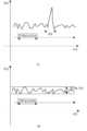
도 4는 본 발명의 실시 예에 따른 클럭을 복원하는 노드에서 위상 점프를 방지지하기 위한 위상 필터링 그래프를 도시하고 있다.FIG. 4 shows a phase filtering graph for supporting a phase jump in a node recovering a clock according to an embodiment of the present invention.
상기 도 4를 참조하면 상기 도 4의 (a)는 위상 필터링을 수행하기 전의 클럭의 위상 그래프를 나타내고, 상기 도 4의 (b)는 위상 필터링을 수행한 클럭의 위상 그래프를 나타낸다.Referring to FIG. 4, FIG. 4 (a) shows a phase graph of a clock before performing phase filtering, and FIG. 4 (b) shows a phase graph of a phase filtered filter.
상기 도 4의 (a)에 도시된 바와 같이 위상 필터링을 수행하지 않는 경우, 마스터 노드에서 전송한 패킷의 지연으로 인해 위상 점프 현상(400)이 발생한다.When phase filtering is not performed as shown in FIG. 4A, a
이때, 슬레이브 노드에서 위상 필터링을 수행하는 경우, 상기 도 4의 (b)에 도시된 바와 같이 위상 이탈을 최소화하여 안정적인 위상의 클럭을 얻을 수 있다.At this time, when phase filtering is performed in the slave node, the phase shift can be minimized and a stable phase clock can be obtained as shown in FIG. 4 (b).
도 5는 본 발명의 실시 예에 따른 클럭을 복원하는 노드에서 협정 세계시와의 오프셋을 최소로 설정하기 위한 그래프를 도시하고 있다.FIG. 5 is a graph for setting an offset from the coordinated time to a minimum in a node restoring a clock according to an embodiment of the present invention.
상기 도 5에 도시된 바와 같이 슬레이브 노드에서 생성한 노드는 신호 지연에 의해 협정 세계시(UTC: Universal Time Coordinated)와의 오프셋이 발생한다.As shown in FIG. 5, a node generated in the slave node generates an offset from Universal Time Coordinated (UTC) due to a signal delay.
이때, 슬레이브 노드는 (T-δ, T)와 (T, T+δ) 샘플링 값에 대한 비교를 지 속적으로 수행하여 위상 확인 구간의 세분화영역들의 최소 클럭 위상을 확인한다. 이후, 상기 슬레이브 노드는 벡터성분을 통한 최소 클럭 위상들 간의 최소 위상 평균 값을 산출하여 출력하는 최종 클럭에 반영한다.At this time, the slave node continuously compares the sampling values of (T-δ, T) and (T, T + δ) to confirm the minimum clock phase of the subdivided areas of the phase verification interval. Then, the slave node calculates the minimum phase average value between the minimum clock phases through the vector components and reflects the minimum phase average value on the final clock output.
상술한 바와 같이 출력하는 최종 클럭에 클럭 위상의 최소 위상 평균 값을 반영하는 경우, 협정 세계시와의 오프셋(510)이 위상 평균 값에 따른 오프셋(500)보다 적으므로 시간 정확도를 높일 수 있다.When the minimum phase average value of the clock phase is reflected to the final clock to be output as described above, the offset 510 from the universal time is less than the offset 500 according to the phase average value, so that the time accuracy can be increased.
도 6은 본 발명의 실시 예에 따른 참조표(Look-Up table)를 도시하고 있다.6 shows a look-up table according to an embodiment of the present invention.
상기 도 6에 도시된 바와 같이 슬레이브 노드는 동작 온도 범위 내의 온도와 그에 따른 위상 정보를 포함하는 참조표를 저장한다. 즉, 상기 참조표는 동작 온도에 따른 위상 정보를 저장한다.As shown in FIG. 6, the slave node stores the reference table including the temperature within the operating temperature range and the corresponding phase information. That is, the reference table stores phase information according to the operating temperature.
이하 설명은 마스터 노드로부터 제공받은 동기 정보에 따라 주파수/시간를 동기화하기 위한 슬레이브 노드의 구성에 대해 설명한다.Hereinafter, a configuration of a slave node for synchronizing frequency / time according to synchronization information provided from a master node will be described.
도 7은 본 발명에 따른 통신시스템에서 클럭을 복원하는 노드의 블록 구성을 도시하고 있다.7 shows a block configuration of a node for restoring a clock in the communication system according to the present invention.
상기 도 7에 도시된 바와 같이 슬레이브 노드는 송수신 인터페이스(701), 지연 확인부(703), 클럭 발생부(705) 및 클럭 보정부(707)를 포함하여 구성된다.7, the slave node includes a transmission /
상기 송수신 인터페이스(701)는 유선망을 통해 마스터 노드와 신호를 송수신한다. 예를 들어, 상기 송수신 인터페이스(701)는 IP 백홀을 통해 마스터 노드로부터 동기 정보를 포함하는 패킷을 수신받는다.The transmission /
상기 지연 확인부(703)는 동기 정보를 전송한 마스터 노드와의 지연을 확인 한다. 예를 들어, 상기 지연 확인부(703)는 상기 송수신 인터페이스(701)를 통해 마스터 노드와 송수신하는 지연 요청 메시지와 지연 응답 메시지의 전송 시점과 수신 시점 정보를 이용하여 상기 마스터 노드와의 지연을 확인한다. 이때, 상기 지연 확인부(703)는 상기 송수신 인터페이스(701)를 통해 동기 정보를 수신될 때 상기 동기 정보를 전송한 마스터 노드와의 지연을 확인한다.The
상기 클럭 발생부(705)는 상기 송수신 인터페이스(701)로부터 제공받은 동기 정보와 상기 지연 확인부(703)로부터 제공받은 마스터 노드와의 지연을 이용하여 주파수 및 시간 동기화된 클럭을 생성한다.The
상기 클럭 보정부(707)는 상기 클럭 발생부(707)에서 생성한 주파수 및 시간 동기화된 클럭의 위상 이탈 값의 변화를 개선하여 출력한다. 예를 들어, 상기 클럭 보정부(707)는 하기 도 8에 도시된 바와 같이 구성된다.The
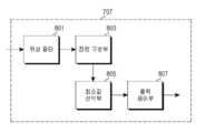
도 8은 본 발명에 따른 클럭을 복원하는 노드에서 클럭 보정부의 상세 블록 구성을 도시하고 있다.FIG. 8 shows a detailed block configuration of a clock correction unit in a node for restoring a clock according to the present invention.
상기 도 8에 도시된 바와 같이 클럭 보정부(707)는 위상 필터(801), 집합 구성부(803), 최소 값 선택부(805) 및 출력 제어부(807)를 포함하여 구성된다.8, the
상기 위상 필터(801)는 상기 클럭 발생부(705)에서 발생한 클럭에서 필터링 구간을 벗어나는 클럭의 위상을 필터링한다. 예를 들어, 상기 위상 필터(801)는 상기 도 4에 도시된 바와 같이 위상 확인 구간에 포함되는 클럭의 위상을 필터링 구간과 비교하여 클럭의 위상을 필터링한다. 여기서, 상기 필터링 구간은 일정 시간 동안 측정한 클럭의 위상 평균을 기준으로 ±오차로 설정된다.The
상기 집합 구성부(803)는 위상 확인 구간을 일정한 크기로 세분화한다. 예를 들어, 상기 집합 구성부(803)는 상기 도 5에 도시된 바와 같이 위상 확인 구간을 T값 별로 세분화한다.The
상기 최소 값 선택부(805)는 상기 집합 구선부(803)에서 세분화한 영역들의 클럭 위상의 최소 값을 선택한다. 예를 들어, 상기 최소 값 선택부(805)는 상기 도 5에 도시된 바와 같이 (T-δ, T)와 (T, T+δ) 샘플링 값에 대한 비교를 지속적으로 수행하여 세분화영역들의 최소 클럭 위상을 선택한다.The minimum
상기 출력 제어부(807)는 상기 최소 값 선택부(805)에서 선택한 세분화 영역들의 최소 클럭 위상을 참조표와 비교하여 출력하기 위한 클럭 위상을 결정한다. 예를 들어, 출력 제어부(807)는 참조표에 포함되는 최소 클럭 위상을 출력한다.The
상술한 실시 예에서 위상 필터(801)는 필터링 구간을 벗어나는 클럭의 위상을 무시한다. 다른 실시 예에서 위상 필터(801)는 필터링 구간을 벗어나는 클럭의 위상 대신 클럭 위상의 평균 값을 출력할 수도 있다.In the above-described embodiment, the
또한, 출력 제어부(807)는 참조표에 포함되지 않는 클럭의 위상을 무시한다. 다른 실시 예에서 출력 제어부(807)는 참조표에 포함되지 않는 클럭의 위상 대신 클럭 위상의 최소 평균 값을 출력할 수도 있다.Further, the
상술한 실시 예에서 슬레이브 노드는 위상 필터링, 협정 세계시와의 오프셋 최소화 및 클럭 위상의 참조표 비교를 모두 수행하여 클럭을 보정한다. 다른 실시 예에서 슬레이브 노드는 상기 세 개의 클럭 보정 방식 중 적어도 하나만을 이용하여 클럭을 보정할 수도 있다.In the above embodiment, the slave node corrects the clock by performing both phase filtering, minimizing the offset with respect to the universal time, and comparing reference tables of the clock phases. In another embodiment, the slave node may correct the clock using only at least one of the three clock correction schemes.
한편 본 발명의 상세한 설명에서는 구체적인 실시 예에 관해 설명하였으나, 본 발명의 범위에서 벗어나지 않는 한도 내에서 여러 가지 변형이 가능하다. 그러므로 본 발명의 범위는 설명된 실시 예에 국한되어 정해져서는 아니 되며 후술하는 특허청구의 범위뿐만 아니라 이 특허청구의 범위와 균등한 것들에 의해 정해져야 한다.While the present invention has been described in connection with what is presently considered to be the most practical and preferred embodiment, it is to be understood that the invention is not limited to the disclosed embodiments. Therefore, the scope of the present invention should not be limited by the illustrated embodiments, but should be determined by the scope of the appended claims and equivalents thereof.
도 1은 종래 기술에 따른 통신시스템에서 트래픽 부하에 따른 클럭의 위상 변화를 도시하는 그래프,1 is a graph showing a phase change of a clock according to a traffic load in a communication system according to the prior art,
도 2는 본 발명에 따른 통신시스템의 구성을 도시하는 도면,2 is a diagram showing a configuration of a communication system according to the present invention;
도 3은 본 발명의 실시 예에 따른 통신시스템에서 클럭을 복원하기 위한 절차를 도시하는 도면,3 is a diagram illustrating a procedure for recovering a clock in a communication system according to an embodiment of the present invention;
도 4는 본 발명의 실시 예에 따른 클럭을 복원하는 노드에서 위상 점프를 방지지하기 위한 위상 필터링을 도시하는 그래프,4 is a graph illustrating phase filtering to support phase jumping in a node restoring a clock according to an embodiment of the present invention;
도 5는 본 발명의 실시 예에 따른 클럭을 복원하는 노드에서 협정 세계시와의 오프셋을 최소로 설정하기 위한 그래프,FIG. 5 is a graph for minimizing an offset from the cooperative world time in a node restoring a clock according to an embodiment of the present invention;
도 6은 본 발명의 실시 예에 따른 참조표(Look-Up table)를 도시하는 그래프,6 is a graph showing a look-up table according to an embodiment of the present invention,
도 7은 본 발명에 따른 통신시스템에서 클럭을 복원하는 노드의 블록 구성을 도시하는 도면, 및7 is a diagram showing a block configuration of a node for restoring a clock in a communication system according to the present invention, and Fig.
도 8은 본 발명에 따른 클럭을 복원하는 노드에서 클럭 보정부의 상세 블록 구성을 도시하는 도면.8 is a detailed block diagram of a clock correction unit in a node for restoring a clock according to the present invention.
Claims (19)
Translated fromKoreanPriority Applications (2)
| Application Number | Priority Date | Filing Date | Title |
|---|---|---|---|
| KR1020090007898AKR101524285B1 (en) | 2009-02-02 | 2009-02-02 | Apparatus and method for timing synchronization in communication system |
| US12/658,038US8472370B2 (en) | 2009-02-02 | 2010-02-01 | Apparatus and method for timing synchronization in a communication system |
Applications Claiming Priority (1)
| Application Number | Priority Date | Filing Date | Title |
|---|---|---|---|
| KR1020090007898AKR101524285B1 (en) | 2009-02-02 | 2009-02-02 | Apparatus and method for timing synchronization in communication system |
Publications (2)
| Publication Number | Publication Date |
|---|---|
| KR20100088791A KR20100088791A (en) | 2010-08-11 |
| KR101524285B1true KR101524285B1 (en) | 2015-06-01 |
Family
ID=42397671
Family Applications (1)
| Application Number | Title | Priority Date | Filing Date |
|---|---|---|---|
| KR1020090007898AExpired - Fee RelatedKR101524285B1 (en) | 2009-02-02 | 2009-02-02 | Apparatus and method for timing synchronization in communication system |
Country Status (2)
| Country | Link |
|---|---|
| US (1) | US8472370B2 (en) |
| KR (1) | KR101524285B1 (en) |
Families Citing this family (7)
| Publication number | Priority date | Publication date | Assignee | Title |
|---|---|---|---|---|
| CN103168440B (en)* | 2012-02-21 | 2016-08-10 | 华为技术有限公司 | Time path compensation method and device |
| EP2928109B1 (en)* | 2012-11-29 | 2017-06-14 | NEC Corporation | Synchronization apparatus, synchronization system, wireless communication apparatus and synchronization method |
| US9160473B2 (en)* | 2013-03-13 | 2015-10-13 | Microsemi Frequency And Time Corporation | Asymmetry correction for precise clock synchronization over optical fiber |
| KR101457473B1 (en)* | 2013-04-25 | 2014-11-07 | (주)씨어스테크놀로지 | Building Management System |
| CN104660359B (en)* | 2013-11-21 | 2019-01-11 | 中兴通讯股份有限公司 | A kind of method, apparatus and equipment of clock frequency deviation detection |
| CN105323054B (en)* | 2014-06-26 | 2019-05-17 | 中兴通讯股份有限公司 | Clock synchronizing method and device |
| US11265139B2 (en)* | 2019-10-23 | 2022-03-01 | Solid, Inc. | Method for transmitting GPS information of optical communication device |
Citations (2)
| Publication number | Priority date | Publication date | Assignee | Title |
|---|---|---|---|---|
| KR19990039697A (en)* | 1997-11-13 | 1999-06-05 | 김영환 | Reference Time Synchronization Method of Redundancy Time / Frequency Generator |
| KR20070055233A (en)* | 2005-11-25 | 2007-05-30 | 삼성전자주식회사 | Satellite Positioning System Time Synchronization Method in Broadband Wireless Access Communication System |
Family Cites Families (10)
| Publication number | Priority date | Publication date | Assignee | Title |
|---|---|---|---|---|
| US5594453A (en)* | 1994-11-01 | 1997-01-14 | Trimble Navigation, Ltd | GPS receiver having a rapid acquisition of GPS satellite signals |
| US8140658B1 (en)* | 1999-10-06 | 2012-03-20 | Borgia/Cummins, Llc | Apparatus for internetworked wireless integrated network sensors (WINS) |
| US6944188B2 (en)* | 2001-02-21 | 2005-09-13 | Wi-Lan, Inc. | Synchronizing clocks across a communication link |
| US7590151B2 (en)* | 2004-02-09 | 2009-09-15 | Semtech Corporation | Method and apparatus for aligning time references when separated by an unreliable data packet network |
| US7643595B2 (en)* | 2004-09-13 | 2010-01-05 | Nortel Networks Limited | Method and apparatus for synchronizing clock timing between network elements |
| US7573914B2 (en)* | 2005-05-12 | 2009-08-11 | Agilent Technologies, Inc. | Systems and methods for synchronizing time across networks |
| JP4186083B2 (en)* | 2006-10-03 | 2008-11-26 | 日本電気株式会社 | Clock synchronization circuit |
| US8010138B2 (en)* | 2007-08-15 | 2011-08-30 | Nokia Corporation | Alternate mobile network cell synchronization |
| US7990909B2 (en)* | 2007-11-02 | 2011-08-02 | Ciena Corporation | Synchronization of network nodes |
| US7876792B2 (en)* | 2008-10-31 | 2011-01-25 | Alcatel Lucent | Network element clocking accuracy and stability monitoring over a packet-switched network |
- 2009
- 2009-02-02KRKR1020090007898Apatent/KR101524285B1/ennot_activeExpired - Fee Related
- 2010
- 2010-02-01USUS12/658,038patent/US8472370B2/ennot_activeExpired - Fee Related
Patent Citations (2)
| Publication number | Priority date | Publication date | Assignee | Title |
|---|---|---|---|---|
| KR19990039697A (en)* | 1997-11-13 | 1999-06-05 | 김영환 | Reference Time Synchronization Method of Redundancy Time / Frequency Generator |
| KR20070055233A (en)* | 2005-11-25 | 2007-05-30 | 삼성전자주식회사 | Satellite Positioning System Time Synchronization Method in Broadband Wireless Access Communication System |
Also Published As
| Publication number | Publication date |
|---|---|
| US20100195565A1 (en) | 2010-08-05 |
| US8472370B2 (en) | 2013-06-25 |
| KR20100088791A (en) | 2010-08-11 |
Similar Documents
| Publication | Publication Date | Title |
|---|---|---|
| KR101524285B1 (en) | Apparatus and method for timing synchronization in communication system | |
| US8953645B2 (en) | Communication system, communication apparatus and time synchronization method | |
| KR101596756B1 (en) | Method and apparatus for providing in-vehicle network time synchronization using redundant GrandMaster | |
| EP2692054B1 (en) | Power converter with dual ring network control | |
| JP2017050730A (en) | Wireless device and base station system | |
| JP5515735B2 (en) | Time synchronization system, master node, slave node, relay device, time synchronization method, and time synchronization program | |
| EP2738971B1 (en) | Method and device for clock synchronization | |
| US8689035B2 (en) | Communication system, communication interface, and synchronization method | |
| US20070081514A1 (en) | Method of synchronizing time between base stations, timing master device, and base station | |
| WO2014083725A1 (en) | Synchronization apparatus, synchronization system, wireless communication apparatus and synchronization method | |
| CN109891960B (en) | Wireless device, wireless device processing method, and memory | |
| JP6036179B2 (en) | Communication device and synchronization method | |
| KR100353107B1 (en) | Frame phase synchronous system and a method thereof | |
| JP5535464B2 (en) | TS signal delay detection adjustment method and apparatus | |
| WO2021255249A1 (en) | Link profiling for assymetric delay compensation | |
| JP2018088646A (en) | Time synchronization device and time synchronization method | |
| JP6170456B2 (en) | Slave node, control server, time synchronization destination determination method and computer program | |
| JP2011091624A (en) | Mesh network system and time synchronizing method thereof | |
| JP6077084B1 (en) | Communication network time synchronization method | |
| JP6327866B2 (en) | Protection relay device and protection system | |
| JP2014165582A (en) | Time synchronization system, time synchronization method, slave node and computer program | |
| EP3736658B1 (en) | Method and device for providing a clock signal | |
| JP2003087175A (en) | Mesh wireless station communication system | |
| JP2012114815A (en) | Phase synchronization device and phase synchronization method | |
| JP5081874B2 (en) | Data collection system |
Legal Events
| Date | Code | Title | Description |
|---|---|---|---|
| PA0109 | Patent application | St.27 status event code:A-0-1-A10-A12-nap-PA0109 | |
| PG1501 | Laying open of application | St.27 status event code:A-1-1-Q10-Q12-nap-PG1501 | |
| R18-X000 | Changes to party contact information recorded | St.27 status event code:A-3-3-R10-R18-oth-X000 | |
| A201 | Request for examination | ||
| PA0201 | Request for examination | St.27 status event code:A-1-2-D10-D11-exm-PA0201 | |
| D13-X000 | Search requested | St.27 status event code:A-1-2-D10-D13-srh-X000 | |
| D14-X000 | Search report completed | St.27 status event code:A-1-2-D10-D14-srh-X000 | |
| E902 | Notification of reason for refusal | ||
| PE0902 | Notice of grounds for rejection | St.27 status event code:A-1-2-D10-D21-exm-PE0902 | |
| P11-X000 | Amendment of application requested | St.27 status event code:A-2-2-P10-P11-nap-X000 | |
| P13-X000 | Application amended | St.27 status event code:A-2-2-P10-P13-nap-X000 | |
| E701 | Decision to grant or registration of patent right | ||
| PE0701 | Decision of registration | St.27 status event code:A-1-2-D10-D22-exm-PE0701 | |
| GRNT | Written decision to grant | ||
| PR0701 | Registration of establishment | St.27 status event code:A-2-4-F10-F11-exm-PR0701 | |
| PR1002 | Payment of registration fee | St.27 status event code:A-2-2-U10-U11-oth-PR1002 Fee payment year number:1 | |
| PG1601 | Publication of registration | St.27 status event code:A-4-4-Q10-Q13-nap-PG1601 | |
| FPAY | Annual fee payment | Payment date:20180427 Year of fee payment:4 | |
| PR1001 | Payment of annual fee | St.27 status event code:A-4-4-U10-U11-oth-PR1001 Fee payment year number:4 | |
| PR1001 | Payment of annual fee | St.27 status event code:A-4-4-U10-U11-oth-PR1001 Fee payment year number:5 | |
| PC1903 | Unpaid annual fee | St.27 status event code:A-4-4-U10-U13-oth-PC1903 Not in force date:20200523 Payment event data comment text:Termination Category : DEFAULT_OF_REGISTRATION_FEE | |
| PC1903 | Unpaid annual fee | St.27 status event code:N-4-6-H10-H13-oth-PC1903 Ip right cessation event data comment text:Termination Category : DEFAULT_OF_REGISTRATION_FEE Not in force date:20200523 |