KR101524176B1 - Information processing device, method for controlling information processing device, program, and information recording medium - Google Patents
Information processing device, method for controlling information processing device, program, and information recording mediumDownload PDFInfo
- Publication number
- KR101524176B1 KR101524176B1KR1020137029858AKR20137029858AKR101524176B1KR 101524176 B1KR101524176 B1KR 101524176B1KR 1020137029858 AKR1020137029858 AKR 1020137029858AKR 20137029858 AKR20137029858 AKR 20137029858AKR 101524176 B1KR101524176 B1KR 101524176B1
- Authority
- KR
- South Korea
- Prior art keywords
- touch sensor
- area
- information processing
- detection
- display
- Prior art date
- Legal status (The legal status is an assumption and is not a legal conclusion. Google has not performed a legal analysis and makes no representation as to the accuracy of the status listed.)
- Active
Links
Images


Classifications
- G—PHYSICS
- G06—COMPUTING OR CALCULATING; COUNTING
- G06F—ELECTRIC DIGITAL DATA PROCESSING
- G06F3/00—Input arrangements for transferring data to be processed into a form capable of being handled by the computer; Output arrangements for transferring data from processing unit to output unit, e.g. interface arrangements
- G06F3/01—Input arrangements or combined input and output arrangements for interaction between user and computer
- G06F3/03—Arrangements for converting the position or the displacement of a member into a coded form
- G06F3/041—Digitisers, e.g. for touch screens or touch pads, characterised by the transducing means
- G06F3/0412—Digitisers structurally integrated in a display
- G—PHYSICS
- G06—COMPUTING OR CALCULATING; COUNTING
- G06F—ELECTRIC DIGITAL DATA PROCESSING
- G06F3/00—Input arrangements for transferring data to be processed into a form capable of being handled by the computer; Output arrangements for transferring data from processing unit to output unit, e.g. interface arrangements
- G06F3/01—Input arrangements or combined input and output arrangements for interaction between user and computer
- G06F3/048—Interaction techniques based on graphical user interfaces [GUI]
- A—HUMAN NECESSITIES
- A63—SPORTS; GAMES; AMUSEMENTS
- A63F—CARD, BOARD, OR ROULETTE GAMES; INDOOR GAMES USING SMALL MOVING PLAYING BODIES; VIDEO GAMES; GAMES NOT OTHERWISE PROVIDED FOR
- A63F13/00—Video games, i.e. games using an electronically generated display having two or more dimensions
- A63F13/20—Input arrangements for video game devices
- A63F13/21—Input arrangements for video game devices characterised by their sensors, purposes or types
- A63F13/214—Input arrangements for video game devices characterised by their sensors, purposes or types for locating contacts on a surface, e.g. floor mats or touch pads
- A63F13/2145—Input arrangements for video game devices characterised by their sensors, purposes or types for locating contacts on a surface, e.g. floor mats or touch pads the surface being also a display device, e.g. touch screens
- A—HUMAN NECESSITIES
- A63—SPORTS; GAMES; AMUSEMENTS
- A63F—CARD, BOARD, OR ROULETTE GAMES; INDOOR GAMES USING SMALL MOVING PLAYING BODIES; VIDEO GAMES; GAMES NOT OTHERWISE PROVIDED FOR
- A63F13/00—Video games, i.e. games using an electronically generated display having two or more dimensions
- A63F13/40—Processing input control signals of video game devices, e.g. signals generated by the player or derived from the environment
- A63F13/42—Processing input control signals of video game devices, e.g. signals generated by the player or derived from the environment by mapping the input signals into game commands, e.g. mapping the displacement of a stylus on a touch screen to the steering angle of a virtual vehicle
- A63F13/426—Processing input control signals of video game devices, e.g. signals generated by the player or derived from the environment by mapping the input signals into game commands, e.g. mapping the displacement of a stylus on a touch screen to the steering angle of a virtual vehicle involving on-screen location information, e.g. screen coordinates of an area at which the player is aiming with a light gun
- A—HUMAN NECESSITIES
- A63—SPORTS; GAMES; AMUSEMENTS
- A63F—CARD, BOARD, OR ROULETTE GAMES; INDOOR GAMES USING SMALL MOVING PLAYING BODIES; VIDEO GAMES; GAMES NOT OTHERWISE PROVIDED FOR
- A63F13/00—Video games, i.e. games using an electronically generated display having two or more dimensions
- A63F13/90—Constructional details or arrangements of video game devices not provided for in groups A63F13/20 or A63F13/25, e.g. housing, wiring, connections or cabinets
- A63F13/92—Video game devices specially adapted to be hand-held while playing
- G—PHYSICS
- G06—COMPUTING OR CALCULATING; COUNTING
- G06F—ELECTRIC DIGITAL DATA PROCESSING
- G06F1/00—Details not covered by groups G06F3/00 - G06F13/00 and G06F21/00
- G06F1/16—Constructional details or arrangements
- G06F1/1613—Constructional details or arrangements for portable computers
- G06F1/1626—Constructional details or arrangements for portable computers with a single-body enclosure integrating a flat display, e.g. Personal Digital Assistants [PDAs]
- G—PHYSICS
- G06—COMPUTING OR CALCULATING; COUNTING
- G06F—ELECTRIC DIGITAL DATA PROCESSING
- G06F1/00—Details not covered by groups G06F3/00 - G06F13/00 and G06F21/00
- G06F1/16—Constructional details or arrangements
- G06F1/1613—Constructional details or arrangements for portable computers
- G06F1/1633—Constructional details or arrangements of portable computers not specific to the type of enclosures covered by groups G06F1/1615 - G06F1/1626
- G06F1/1684—Constructional details or arrangements related to integrated I/O peripherals not covered by groups G06F1/1635 - G06F1/1675
- G06F1/169—Constructional details or arrangements related to integrated I/O peripherals not covered by groups G06F1/1635 - G06F1/1675 the I/O peripheral being an integrated pointing device, e.g. trackball in the palm rest area, mini-joystick integrated between keyboard keys, touch pads or touch stripes
- G06F1/1692—Constructional details or arrangements related to integrated I/O peripherals not covered by groups G06F1/1635 - G06F1/1675 the I/O peripheral being an integrated pointing device, e.g. trackball in the palm rest area, mini-joystick integrated between keyboard keys, touch pads or touch stripes the I/O peripheral being a secondary touch screen used as control interface, e.g. virtual buttons or sliders
- G—PHYSICS
- G06—COMPUTING OR CALCULATING; COUNTING
- G06F—ELECTRIC DIGITAL DATA PROCESSING
- G06F3/00—Input arrangements for transferring data to be processed into a form capable of being handled by the computer; Output arrangements for transferring data from processing unit to output unit, e.g. interface arrangements
- G06F3/01—Input arrangements or combined input and output arrangements for interaction between user and computer
- G06F3/048—Interaction techniques based on graphical user interfaces [GUI]
- G06F3/0487—Interaction techniques based on graphical user interfaces [GUI] using specific features provided by the input device, e.g. functions controlled by the rotation of a mouse with dual sensing arrangements, or of the nature of the input device, e.g. tap gestures based on pressure sensed by a digitiser
- G06F3/0488—Interaction techniques based on graphical user interfaces [GUI] using specific features provided by the input device, e.g. functions controlled by the rotation of a mouse with dual sensing arrangements, or of the nature of the input device, e.g. tap gestures based on pressure sensed by a digitiser using a touch-screen or digitiser, e.g. input of commands through traced gestures
- G06F3/04886—Interaction techniques based on graphical user interfaces [GUI] using specific features provided by the input device, e.g. functions controlled by the rotation of a mouse with dual sensing arrangements, or of the nature of the input device, e.g. tap gestures based on pressure sensed by a digitiser using a touch-screen or digitiser, e.g. input of commands through traced gestures by partitioning the display area of the touch-screen or the surface of the digitising tablet into independently controllable areas, e.g. virtual keyboards or menus
- G—PHYSICS
- G06—COMPUTING OR CALCULATING; COUNTING
- G06F—ELECTRIC DIGITAL DATA PROCESSING
- G06F2203/00—Indexing scheme relating to G06F3/00 - G06F3/048
- G06F2203/048—Indexing scheme relating to G06F3/048
- G06F2203/04803—Split screen, i.e. subdividing the display area or the window area into separate subareas
- G—PHYSICS
- G06—COMPUTING OR CALCULATING; COUNTING
- G06F—ELECTRIC DIGITAL DATA PROCESSING
- G06F2203/00—Indexing scheme relating to G06F3/00 - G06F3/048
- G06F2203/048—Indexing scheme relating to G06F3/048
- G06F2203/04808—Several contacts: gestures triggering a specific function, e.g. scrolling, zooming, right-click, when the user establishes several contacts with the surface simultaneously; e.g. using several fingers or a combination of fingers and pen
Landscapes
- Engineering & Computer Science (AREA)
- Multimedia (AREA)
- Theoretical Computer Science (AREA)
- Human Computer Interaction (AREA)
- General Engineering & Computer Science (AREA)
- Physics & Mathematics (AREA)
- General Physics & Mathematics (AREA)
- Computer Hardware Design (AREA)
- User Interface Of Digital Computer (AREA)
- Position Input By Displaying (AREA)
Abstract
Translated fromKorean
Description
Translated fromKorean본 발명은 정보처리장치, 정보처리장치의 제어방법, 프로그램 및 정보기억 매체에 관한 것이다.The present invention relates to an information processing apparatus, a control method of an information processing apparatus, a program, and an information storage medium.
최근, 정보처리장치에 대하여 조작 입력을 실시하는 방법으로서 다양한 것이 제안되고 있다. 특허문헌 1에는 기기의 양면에 센서를 배치하고, 이들 쌍방의 센서로 조작 입력을 실시하도록 한 기기가 기재되어 있다.2. Description of the Related Art In recent years, various methods have been proposed as methods for inputting an operation to an information processing apparatus.
예를 들어 사용자가 전면(前面)에 디스플레이와 터치센서가 겹쳐서 배치되어 있는 정보처리장치를 왼손으로 들고, 오른손 손가락으로 전면측의 터치센서를 조작했을 때에, 표시 대상이 되는 정보가 디스플레이의 우측 아래에 표시되면, 사용자의 손에 의해 이 정보가 가려져서 사용자가 이 정보를 보기 힘들게 될 가능성이 높다. 한편 사용자가 상술한 정보처리장치를 오른손으로 들고, 왼손 손가락으로 전면측의 터치센서를 조작했을 때에는, 표시 대상이 되는 정보가 디스플레이의 좌측 아래에 표시되면, 사용자의 손에 의해 이 정보가 가려져서 사용자가 이 정보를 보기 힘들게 될 가능성이 높다.For example, when the user holds the information processing device in which the display and the touch sensor are placed on the front surface with the left hand and the touch sensor on the front side is operated with the right hand finger, information to be displayed is displayed on the lower right side This information is hidden by the user's hand, and it is highly likely that the user will not be able to view this information. On the other hand, when the user holds the aforementioned information processing apparatus with his right hand and operates the touch sensor on the front side with his left finger, if the information to be displayed is displayed on the lower left of the display, this information is hidden by the user's hand, This information is likely to be hard to see.
이와 같이 디스플레이 내에서 사용자가 보기 힘든 영역은 사용자가 정보처리장치를 드는 손에 따라 변하는 것이라고 생각된다. 그렇기 때문에 정보처리장치를 드는 손에 따라서 디스플레이 내에서 정보가 표시되지 않는 영역이 변하게 되면 편리하다.In this way, it is considered that the area which is difficult for the user to see in the display varies depending on the hand of the user lifting the information processing apparatus. Therefore, it is convenient to change the area where information is not displayed in the display depending on the hand holding the information processing apparatus.
또 정보처리장치의 배면에 터치센서를 마련하면, 예를 들면 이 터치센서에 의한 검출위치를, 사용자가 정보처리장치를 오른손으로 들고 있는지 왼손으로 들고 있는지 추정하는데 활용할 수 있다고 생각된다. 이와 같이 정보처리장치의 배면의 터치센서는 디스플레이 내에서 정보가 표시되지 않는 영역의 제어에 도움이 되는 것이라고 생각된다.Further, if the touch sensor is provided on the back surface of the information processing apparatus, for example, it is considered that the detection position by the touch sensor can be utilized for estimating whether the user holds the information processing apparatus with his right or left hand. Thus, it is considered that the touch sensor on the back surface of the information processing apparatus is helpful in controlling the area where information is not displayed in the display.
본 발명은 상기 과제를 감안하여 이루어진 것으로서, 그 목적 중 하나는 디스플레이에 겹쳐서 배치되어 있는 터치센서에 대향하여 배치되는 터치센서의 검출위치에 따라서, 디스플레이 내에서 표시 대상이 되는 정보가 표시되지 않는 영역을 바꿀 수 있도록 하는 것에 있다.SUMMARY OF THE INVENTION The present invention has been made in view of the above-described problems, and one of its objects is to provide a touch sensor which is arranged in a stacked manner on a display, To be able to change.
상기 과제를 해결하기 위해서, 본 발명에 따른 정보처리장치는 표시부와, 상기 표시부에 겹쳐서 배치되어 있는, 검출면상에서의 물체의 위치를 검출하는 전면 터치센서와, 상기 전면 터치센서에 대향하여 배치되는, 검출면상에서의 물체의 위치를 검출하는 배면 터치센서와, 제어부를 구비하고, 상기 제어부는 상기 배면 터치센서에 의한 적어도 하나의 검출위치에 기초하여 각각 상기 표시부의 일부를 차지하는 좌우에 배치된 2개의 영역 중 한쪽을 금지영역으로서 특정하고, 표시 대상이 되는 정보를 상기 표시부 내의 상기 금지영역 이외의 영역에 표시시키는 것을 특징으로 한다.In order to solve the above problems, an information processing apparatus according to the present invention includes a display unit, a front touch sensor which is disposed on the display unit and detects the position of an object on a detection surface, A back surface touch sensor for detecting the position of an object on the detection surface, and a control unit, wherein the control unit is configured to detect the position of the object based on at least one detection position by the back surface touch sensor, One of the areas is specified as a forbidden area, and information to be displayed is displayed in an area other than the forbidden area in the display section.
또 본 발명에 따른 정보처리장치의 제어방법은, 표시부와, 상기 표시부에 겹쳐서 배치되어 있는, 검출면상에서의 물체의 위치를 검출하는 전면 터치센서와, 상기 전면 터치센서에 대향하여 배치되는, 검출면상에서의 물체의 위치를 검출하는 배면 터치센서를 구비하는 정보처리장치의 제어방법으로서, 상기 배면 터치센서에 의한 적어도 하나의 검출위치에 기초하여 각각 상기 표시부의 일부를 차지하는 좌우에 배치된 2개의 영역 중 한쪽을 금지영역으로서 특정하고, 표시 대상이 되는 정보를 상기 표시부 내의 상기 금지영역 이외의 영역에 표시시키는 것을 특징으로 한다.A control method for an information processing apparatus according to the present invention is a control method for an information processing apparatus comprising a display unit, a front touch sensor disposed on the display unit for detecting a position of an object on a detection surface, A method of controlling an information processing apparatus having a back surface touch sensor for detecting a position of an object on a surface, comprising the steps of: determining, based on at least one detection position by the back surface touch sensor, One of the areas is specified as a forbidden area, and information to be displayed is displayed in an area other than the forbidden area in the display part.
또 본 발명에 따른 프로그램은, 표시부와, 상기 표시부에 겹쳐서 배치되어 있는, 검출면상에서의 물체의 위치를 검출하는 전면 터치센서와, 상기 전면 터치센서에 대향하여 배치되는, 검출면상에서의 물체의 위치를 검출하는 배면 터치센서를 구비하는 정보처리장치에, 각각 상기 표시부의 일부를 차지하는 좌우에 배치된 2개의 금지영역 중 한쪽을, 상기 배면 터치센서에 의한 적어도 하나의 검출위치에 기초하여 특정하는 순서와, 표시 대상이 되는 정보를 상기 표시부 내의 특정된 금지영역 이외의 영역에 표시시키는 순서를 실행시키는 것을 특징으로 한다.According to another aspect of the present invention, there is provided a program for causing a computer to function as: a display unit; a front touch sensor disposed on the display unit for detecting a position of an object on a detection surface; The information processing apparatus including a back surface touch sensor for detecting a position of each of the two prohibited areas disposed on the left and right sides occupying a part of the display unit on the basis of at least one detection position by the back surface touch sensor And displaying the information to be displayed on an area other than the specified forbidden area in the display unit.
또 본 발명에 따른 정보기억 매체는, 표시부와, 상기 표시부에 겹쳐서 배치되어 있는, 검출면상에서의 물체의 위치를 검출하는 전면 터치센서와, 상기 전면 터치센서에 대향하여 배치되는, 검출면상에서의 물체의 위치를 검출하는 배면 터치센서를 구비하는 정보처리장치에, 각각 상기 표시부의 일부를 차지하는 좌우에 배치된 2개의 금지영역 중 한쪽을, 상기 배면 터치센서에 의한 적어도 하나의 검출위치에 기초하여 특정하는 순서와, 표시 대상이 되는 정보를 상기 표시부 내의 특정된 금지영역 이외의 영역에 표시시키는 순서를 실행시키는 것을 특징으로 하는 프로그램을 기억한 컴퓨터 판독 가능한 정보기억 매체이다.According to another aspect of the present invention, there is provided an information storage medium including a display unit, a front touch sensor disposed on the display unit for detecting a position of an object on a detection surface, An information processing apparatus having a rear surface touch sensor for detecting the position of an object is provided with one of two left and right forbidden regions occupying a part of the display unit on the basis of at least one detection position by the rear surface touch sensor And displaying the information to be displayed on an area other than the specified forbidden area in the display unit. The computer-readable information storage medium according to
본 발명에 따르면 배면 터치센서에 의한 검출위치에 의해 특정되는 금지영역 이외의 영역에 표시 대상이 되는 정보가 표시되므로, 디스플레이에 겹쳐서 배치되어 있는 터치센서에 대향하여 배치되는 터치센서의 검출위치에 따라서, 디스플레이 내에서 표시 대상이 되는 정보가 표시되지 않는 영역을 바꿀 수 있게 된다.According to the present invention, since the information to be displayed is displayed in an area other than the forbidden area specified by the detection position by the rear surface touch sensor, the information to be displayed is displayed in accordance with the detection position of the touch sensor disposed to face the touch sensor , It is possible to change the area in which the display target information is not displayed in the display.
본 발명의 일양태에서는 상기 표시부의 짧은 길이방향이 연직(鉛直)방향을 따른 방향인지, 상기 표시부의 긴 길이방향이 연직방향을 따른 방향인지에 따라서 상기 배면 터치센서에 의한 검출위치와, 상기 2개의 영역 중에서 특정되는 상기 금지영역의 대응 관계가 역전되는 것을 특징으로 한다.According to an embodiment of the present invention, the detection position by the backside touch sensor and the detection position by the backside touch sensor are determined according to whether the short length direction of the display unit is along the vertical direction or the long length direction of the display unit is along the vertical direction, The corresponding relationship of the forbidden area specified in the area is reversed.
또 본 발명의 일양태에서는, 상기 제어부가, 상기 배면 터치센서에 의한 1의 검출위치가, 상기 전면 터치센서의 좌측 절반에 대향하는 상기 배면 터치센서 내의 영역 내에 존재하는지, 상기 전면 터치센서의 우측 절반에 대향하는 상기 배면 터치센서 내의 영역 내에 존재하는지에 기초하여 상기 2개의 영역 중 한쪽을 상기 금지영역으로서 특정하는 것을 특징으로 한다.In one aspect of the present invention, the control unit determines whether the detection position of 1 by the rear surface touch sensor is within an area within the rear surface touch sensor opposed to the left half of the front surface touch sensor, One of the two areas is specified as the forbidden area on the basis of whether or not the area is within the area in the rear surface touch sensor opposed to the half.
또 본 발명의 일양태에서는 상기 배면 터치센서에 의한 1의 검출위치가 상기 전면 터치센서의 좌측 절반에 대향하는 상기 배면 터치센서 내의 영역 내에 존재할 경우에 상기 2개의 영역 중 좌측 영역을 상기 금지영역으로서 특정하고, 그렇지 않은 경우에 상기 2개의 영역 중 우측 영역을 상기 금지영역으로서 특정하는 것을 특징으로 한다.According to an embodiment of the present invention, when the detection position of 1 by the rear surface touch sensor exists in an area within the rear surface touch sensor opposed to the left half of the front surface touch sensor, the left area of the two areas is referred to as the forbidden area And specifies the right area of the two areas as the forbidden area if the area is not specified.
또 본 발명의 일양태에서는 상기 표시부의 방향을 검출하는 방향검출부를 더 구비하고, 상기 제어부는, 상기 방향검출부에 의한 검출결과에 기초하여 상기 표시부의 긴 길이방향이 연직방향을 따른 방향인지, 상기 표시부의 짧은 길이방향이 연직방향을 따른 방향인지를 판정하여, 상기 표시부의 짧은 길이방향이 연직방향을 따른 방향이라고 판정될 때에는 상기 배면 터치센서에 의한 1의 검출위치가 상기 전면 터치센서의 좌측 절반에 대향하는 상기 배면 터치센서 내의 영역 내에 존재할 경우에 상기 2개의 영역 중 좌측 영역을 상기 금지영역으로서 특정하고, 그렇지 않은 경우에 상기 2개의 영역 중 우측 영역을 상기 금지영역으로서 특정하며, 상기 표시부의 긴 길이방향이 연직방향을 따른 방향이라고 판정될 때에는 상기 배면 터치센서에 의한 1의 검출위치가 상기 전면 터치센서의 좌측 절반에 대향하는 상기 배면 터치센서 내의 영역 내에 존재할 경우에 상기 2개의 영역 중 우측 영역을 상기 금지영역으로서 특정하고, 그렇지 않은 경우에 상기 2개의 영역 중 좌측 영역을 상기 금지영역으로서 특정하는 것을 특징으로 한다.According to another aspect of the present invention, there is further provided a direction detecting unit for detecting a direction of the display unit, wherein the control unit determines whether the long direction of the display unit is a direction along the vertical direction, When the short length direction of the display unit is determined to be the direction along the vertical direction, the detection position of 1 by the rear surface touch sensor is determined as the left half of the front touch sensor The left side area of the two areas is specified as the forbidden area, and if not, the right side area of the two areas is designated as the forbidden area, And when it is determined that the long direction is the direction along the vertical direction, The right side region of the two regions is specified as the forbidden region when the detection position is present in a region in the rear surface touch sensor opposed to the left half of the front side touch sensor, As the prohibited area.
또 본 발명의 일양태에서는, 상기 제어부는 상기 전면 터치센서에 의한 검출위치에 기초하여 상기 2개의 영역의 위치를 결정하는 것을 특징으로 한다.According to an embodiment of the present invention, the control unit determines the positions of the two areas based on the detection position of the front touch sensor.
또 본 발명의 일양태에서는 상기 제어부는, 상기 전면 터치센서에 의한 검출위치의 좌측 아래에 위치하는 상기 표시부 내의 영역을 상기 2개의 영역 중 좌측 영역으로서 결정하고, 상기 전면 터치센서에 의한 검출위치의 우측 아래에 위치하는 상기 표시부 내의 영역을 상기 2개의 영역 중 우측 영역으로서 결정하는 것을 특징으로 한다.In one embodiment of the present invention, the control unit determines an area in the display unit located at the lower left of the detection position by the front touch sensor as a left area of the two areas, And an area in the display unit located at the lower right is determined as a right area of the two areas.
또 본 발명의 일양태에서는, 상기 제어부는 표시 대상이 되는 정보가 복수 존재하고, 상기 복수의 정보가 순서지어져 있는 경우에, 상기 표시부 내의 상기 금지영역 이외의 영역을 분할한 복수의 순서지어진 영역 내에, 상기 순서지어진 복수의 정보를, 정보의 순서와 영역의 순서가 대응하도록 분할된 각 영역에 표시시키는 것을 특징으로 한다.According to an embodiment of the present invention, in the case where a plurality of pieces of information to be displayed are present and the plurality of pieces of information are ordered, And displaying the plurality of pieces of information in the divided areas in such a manner that the order of the information corresponds to the order of the area.
도 1a는 본 발명의 일실시형태에 따른 정보처리장치의 외관을 나타내는 사시도이다.
도 1b는 본 발명의 일실시형태에 따른 정보처리장치의 외관을 나타내는 사시도이다.
도 2는 본 발명의 일실시형태에 따른 정보처리장치의 하드웨어 구성의 일례를 나타내는 도면이다.
도 3은 본 발명의 일실시형태에 따른 정보처리장치에서 실현되는 기능의 일례를 나타내는 기능 블록도이다.
도 4a는 사용자가 정보처리장치를 가로방향으로 왼손으로 쥐고 있는 모습의 일례를 나타내는 도면이다.
도 4b는 사용자가 정보처리장치를 세로방향으로 왼손으로 쥐고 있는 모습의 일례를 나타내는 도면이다.
도 4c는 사용자가 정보처리장치를 가로방향으로 오른손으로 쥐고 있는 모습의 일례를 나타내는 도면이다.
도 4d는 사용자가 정보처리장치를 세로방향으로 오른손으로 쥐고 있는 모습의 일례를 나타내는 도면이다.
도 5는 본 발명의 일실시형태에 따른 정보처리장치에서 실행되는 처리의 흐름의 일례를 나타내는 흐름도이다.
도 6a는 평균 좌표법의 설명도이다.
도 6b는 평균 좌표법의 설명도이다.
도 6c는 벡터 그레디언트법(vector gradient method)의 설명도이다.
도 6d는 벡터 외적법(vector cross product method)의 설명도이다.
도 6e는 벡터 외적법의 설명도이다.
도 7a는 금지영역 및 우선영역의 일례를 나타내는 도면이다.
도 7b는 금지영역 및 우선영역의 일례를 나타내는 도면이다.FIG. 1A is a perspective view showing the appearance of an information processing apparatus according to an embodiment of the present invention. FIG.
1B is a perspective view showing an appearance of an information processing apparatus according to an embodiment of the present invention.
2 is a diagram showing an example of a hardware configuration of an information processing apparatus according to an embodiment of the present invention.
3 is a functional block diagram showing an example of a function realized by an information processing apparatus according to an embodiment of the present invention.
4A is a view showing an example of a user holding the information processing apparatus with his left hand in a lateral direction.
4B is a view showing an example of a user holding the information processing apparatus with his left hand in the longitudinal direction.
4C is a view showing an example of a user holding the information processing apparatus with his right hand in the lateral direction.
4D is a diagram showing an example of a user holding the information processing apparatus with his right hand in the longitudinal direction.
5 is a flowchart showing an example of the flow of processing executed in an information processing apparatus according to an embodiment of the present invention.
6A is an explanatory diagram of an average coordinate method.
6B is an explanatory diagram of an average coordinate method.
6C is an explanatory diagram of the vector gradient method.
Figure 6d is an illustration of the vector cross product method.
6E is an explanatory diagram of the vector external method.
7A is a diagram showing an example of a prohibited area and a priority area.
Fig. 7B is a diagram showing an example of a prohibited area and a priority area.
이하, 본 발명의 실시형태에 대해서 도면에 기초해 상세하게 설명한다.BEST MODE FOR CARRYING OUT THE INVENTION Hereinafter, embodiments of the present invention will be described in detail with reference to the drawings.
도 1a 및 도 1b는 본 발명의 일실시형태에 따른 정보처리장치(1)의 외관을 나타내는 사시도이며, 도 1a는 정보처리장치(1)를 전면측에서 본 모습을, 도 1b는 배면측에서 본 모습을 각각 나타내고 있다. 본 실시형태에 따른 정보처리장치(1)는 예를 들면 휴대형 게임기 등의 가반형(可搬型) 디바이스인 것으로 한다.1A and 1B are perspective views showing the external appearance of an
이들 도면에 도시되는 바와 같이 정보처리장치(1)의 하우징(10)은 전체적으로 대략 직사각형의 평판형상의 형상을 하고 있다. 이하에서는 하우징(10)의 가로방향(폭방향)을 X축방향, 세로방향(높이방향)을 Y축방향으로 하고, 두께방향(깊이방향)을 Z축방향으로 한다. 또 본 실시형태에서는 하우징(10)의 전면에서 봤을 때 왼쪽에서 오른쪽으로 향하는 방향이 X축 양방향, 하우징(10)의 전면에서 봤을 때 아래에서 위로 향하는 방향이 Y축 양방향, 하우징(10)의 배면에서 전면으로 향하는 방향이 Z축 양방향으로 되어 있다.As shown in these drawings, the
하우징(10)의 전면에는 터치패널(12)이 마련되어 있다. 터치패널(12)은 대략 직사각형의 형상을 하고 있고, 디스플레이(14)와 전면 터치센서(16)를 포함하여 구성되어 있다. 디스플레이(14)는 액정표시 패널이나 유기EL표시 패널 등, 각종 화상표시 디바이스여도 된다.On the front surface of the
전면 터치센서(16)는 디스플레이(14)에 겹쳐서 배치되어 있고 디스플레이(14)의 표시면에 대응하는 형상 및 크기의 대략 직사각형의 검출면을 구비하고 있다. 그리고, 본 실시형태에서는 전면 터치센서(16)는 소정의 시간간격으로 이 검출면상에서의 사용자의 손가락이나 스타일러스 등의 물체의 접촉을 순차 검출한다. 전면 터치센서(16)는 물체의 접촉을 검출했을 경우는 그 물체의 접촉 위치를 검출한다. 또한 전면 터치센서(16)는 반드시 물체가 검출면에 접촉했을 경우에만 물체의 위치를 검출하는 것이 아니라, 검출면상의 검출 가능범위 내까지 물체가 근접했을 경우에 해당 물체의 검출면에 대한 위치를 검출해도 된다. 또 전면 터치센서(16)는 예를 들면 정전용량식이나 감압식, 광학식 등, 검출면상에서의 물체의 위치를 검출가능한 디바이스라면 어떤 방식이어도 된다. 또한 본 실시형태에서는, 전면 터치센서(16)는 여러 군데(예를 들면, 최대 8군데)에서의 물체의 접촉을 검지 가능한 다점(多点) 검지형 터치센서인 것으로 한다. 또 전면 터치센서(16)는 물체의 검출면에 닿아 있는 부분의 면적(접촉면적)이나, 물체가 검출면을 누르는 강도(압력)를 검출가능한 센서여도 된다.The
또한 본 실시형태에서는 하우징(10)의 배면측에 전면 터치센서(16)와 대향하도록 배면 터치센서(18)가 배치되어 있다. 또 본 실시형태에서는 배면 터치센서(18)는 하우징(10)의 정면에서 봤을 때 배면 터치센서(18)의 좌측 절반이 전면 터치센서(16)의 좌측 절반에 대향하고, 배면 터치센서(18)의 우측 절반이 전면 터치센서(16)의 우측 절반에 대향하도록 배치되어 있다. 이 배면 터치센서(18)는 전면 터치센서(16)보다도 X축방향의 길이가 길고, 전면 터치센서(16)보다도 Y축방향의 길이가 짧은 대략 직사각형의 검출면을 구비하고 있으며, 전면 터치센서(16)와 마찬가지로 소정의 시간간격으로 검출면상에서의 물체의 위치를 검출한다. 즉, 디스플레이(14)의 표시면, 전면 터치센서(16)의 검출면, 및 배면 터치센서(18)의 검출면은 각각 하우징(10)의 XY평면과 평행한 방향으로 배치되고, 하우징(10)의 두께방향(Z축방향)을 따라 직선상으로 나열되어 있다. 본 실시형태에서는 배면 터치센서(18)는 전면 터치센서(16)와 마찬가지로 여러 군데에서의 물체의 접촉을 검지 가능한 다점 검지형 터치센서인 것으로 한다. 배면 터치센서(18)는 전면 터치센서(16)와 마찬가지로 각종 방식의 것이어도 된다. 또한 전면 터치센서(16)와 배면 터치센서(18)는 서로 대향하여 배치되어 있으면, 상술한 바와 같이 배면 터치센서(18)가 전면 터치센서(16)보다도 X축방향의 길이가 길 필요도 없고, 배면 터치센서(18)가 전면 터치센서(16)보다도 Y축방향의 길이가 짧을 필요도 없다. 예를 들면 전면 터치센서(16)와 배면 터치센서(18)가 서로 대략 같은 형태, 대략 같은 사이즈여도 무방하다.In the present embodiment, the rear
또 본 실시형태에 따른 정보처리장치(1)의 전면 및 상측면에는 버튼(20)이 마련되어 있다. 본 실시형태에서는 정보처리장치(1)의 전면에 대해서는 디스플레이(14)의 좌측에 각각이 상하좌우 중 어느 한 방향에 대응되는 4개의 버튼(20)(방향 버튼군)이 마련되어 있고, 디스플레이(14)의 우측에는 4개의 버튼(20)이 마련되어 있다. 또 정보처리장치(1)의 상측면에는 좌우에 2개의 버튼(20)이 배치되어 있다.In the
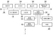
도 2는 도 1a 및 도 1b에 도시한 정보처리장치(1)의 하드웨어 구성의 일례를 나타내는 구성도이다. 도 2에 도시한 바와 같이 정보처리장치(1)는 이미 설명한 디스플레이(14), 전면 터치센서(16), 배면 터치센서(18), 버튼(20) 이외에, 제어부(22), 기억부(24), 통신부(26), 광디스크 판독부(28), 스피커(30), 입력 인터페이스(32), 방향검출부(34)를 포함하여 구성되어 있다. 그리고 본 실시형태에서는 디스플레이(14), 제어부(22), 기억부(24), 통신부(26), 광디스크 판독부(28), 스피커(30), 입력 인터페이스(32)가 내부 버스(36)를 통해 접속되어 있다.Fig. 2 is a configuration diagram showing an example of the hardware configuration of the
제어부(22)는 예를 들면 CPU 등으로서, 기억부(24)에 저장되어 있는 프로그램에 따라 각종 정보처리를 실행한다. 기억부(24)는 예를 들면 RAM이나 ROM 등의 메모리 소자나, 디스크 디바이스 등이며, 제어부(22)에 의해 실행되는 프로그램이나 각종 데이터를 저장한다. 또 기억부(24)는 제어부(22)의 워크 메모리로서도 기능한다. 통신부(26)는 예를 들면 네트워크 인터페이스 등(구체적으로는, 예를 들면 무선 LAN 모듈)으로서 제어부(22)로부터 입력되는 지시에 따라서 다른 정보처리장치(1)나 인터넷상의 서버(미도시) 등에 정보를 송신한다. 또 통신부(26)는 수신되는 정보를 제어부(22)에 출력한다. 광디스크 판독부(28)는 제어부(22)로부터의 지시에 따라서 광디스크에 기억된 프로그램이나 데이터를 판독한다. 또한 정보처리장치(1)는 광디스크 이외의 다른 컴퓨터 판독 가능한 정보기억 매체에 기억된 프로그램이나 데이터를 독취 가능하게 구성해도 된다. 스피커(30)는 제어부(22)로부터 접수하는 지시에 따라서 음성을 외부에 출력한다. 방향검출부(34)는 하우징(10)의 방향을 검출하는 센서이다. 본 실시형태에서 방향검출부(34)는 예를 들면 중력가속도의 방향을 검출할 수 있는 3축 가속도 센서이며, 방향검출부(34)에 의해 하우징(10)이 연직방향에 대하여 어떤 방향으로 되어 있는지를 검출할 수 있다. 방향검출부(34)는, 본 실시형태에서는 소정의 시간간격으로 하우징(10)이 연직방향에 대하여 어떤 방향으로 되어 있는지를 검출한다.The
또 본 실시형태에서 입력 인터페이스(32)에는 전면 터치센서(16), 배면 터치센서(18), 방향검출부(34), 버튼(20)이 접속된다. 그리고 전면 터치센서(16), 배면 터치센서(18), 방향검출부(34) 또는 버튼(20)과, 제어부(22) 사이의 데이터의 수수(授受)는 입력 인터페이스(32)를 통해 이루어진다.A
도 3은 본 실시형태에 따른 정보처리장치(1)에서 실현되는 기능의 일례를 나타내는 기능 블록도이다. 도 3에 도시한 바와 같이 본 실시형태에 따른 정보처리장치(1)는 검출결과 접수부(40), 쥔 손 판정부(42), 좌우 플래그 유지부(44), 디스플레이방향 판정부(46), 영역특정부(48), 표시처리 실행부(50)를 포함하는 것으로서 기능한다. 좌우 플래그 유지부(44)는 기억부(24)를 주로 하여 실현된다. 검출결과 접수부(40)는 제어부(22), 전면 터치센서(16), 배면 터치센서(18), 방향검출부(34)를 주로 하여 실현된다. 그 밖의 요소는 제어부(22)를 주로 하여 실현된다. 이 요소들은 컴퓨터인 정보처리장치(1)에 인스톨된 프로그램을 정보처리장치(1)의 제어부(22)에서 실행함으로써 실현되고 있다. 이 프로그램은 예를 들면 CD-ROM, DVD-ROM 등의 컴퓨터로 읽을 수 있는 정보전달 매체를 통해, 혹은 인터넷 등의 통신 네트워크를 통해 정보처리장치(1)에 공급된다.3 is a functional block diagram showing an example of functions realized in the
사용자는 본 실시형태에 따른 정보처리장치(1)의 전면 터치센서(16)나 배면 터치센서(18)의 검출면상에 자신의 손가락을 접촉시키거나, 이들의 검출면상에 손가락을 접촉시킨 상태로 손가락을 움직임으로써 정보처리장치(1)에 대한 조작 입력을 실시한다. 또 사용자는 버튼(20)을 누름으로써도 정보처리장치(1)에 대한 조작 입력을 실시할 수 있도록 되어 있다.The user touches his or her finger on the detection surface of the
또 일반적으로 사용자는 한손 또는 양손으로 본 실시형태에 따른 정보처리장치(1)를 쥐고 상술한 조작 입력을 실시하게 된다. 또 사용자는 정보처리장치(1)에서 실행되고 있는 애플리케이션 프로그램의 종류 등에 따라서는, 본 실시형태에 따른 정보처리장치(1)를 가로방향으로 쥐는(짧은 길이방향을 따른 가장가지를 쥐는) 경우도 있고, 세로방향으로 쥐는(긴 길이방향을 따른 가장가지를 쥐는) 경우도 있다고 생각된다. 또 사용자는 정보처리장치(1)를 한손으로 쥘 때에 왼손으로 쥐는 경우도 있고, 오른손으로 쥐는 경우도 있다고 생각된다.In general, the user holds the
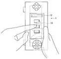
도 4a에 사용자가 정보처리장치(1)를 가로방향으로 왼손으로 쥐고 있는 모습의 일례를 도시한다. 도 4b에 사용자가 정보처리장치(1)를 세로방향으로 왼손으로 쥐고 있는 모습의 일례를 도시한다. 도 4c에 사용자가 정보처리장치(1)를 가로방향으로 오른손으로 쥐고 있는 모습의 일례를 도시한다. 도 4d에 사용자가 정보처리장치(1)를 세로방향으로 오른손으로 쥐고 있는 모습의 일례를 도시한다.FIG. 4A shows an example of a user holding the
그리고 본 실시형태에 따른 정보처리장치(1)에서는 도 4a, 도 4b, 도 4c, 및 도 4d에 도시되어 있는 바와 같이, 사용자는 정보처리장치(1)를 쥐고 있지 않은 손의 손가락으로 전면 터치센서(16)를 터치하여 조작 입력을 실시할 수 있도록 되어 있다. 도 4a, 도 4b, 도 4c, 및 도 4d에서는, 사용자는 손가락으로 정보처리장치(1)에 대한 조작 입력을 실시하고 있지만, 스타일러스 등으로 정보처리장치(1)에 대하여 조작 입력을 실시해도 물론 무방하다. 그리고 본 실시형태에 따른 정보처리장치(1)에서는 예를 들면 사용자가 전면 터치센서(16)를 터치하면, 그 터치된 위치에 따른 정보(예를 들면 터치된 위치에 표시되어 있는 아이콘으로부터 손가락을 뗌으로써 실행되는 처리 내용을 나타내는 정보)가 그 터치된 위치에 대응되는 디스플레이(14)상의 위치에 표시되도록 되어 있다. 그리고 도 4a 및 도 4b에 도시한 바와 같이 정보처리장치(1)가 사용자의 왼손에 쥐어져 있을 경우에는 전면 터치센서(16)의 터치된 위치에 대응되는 디스플레이(14)상의 위치를 기준으로 하여 좌측 위쪽의 영역에 표시 대상이 되는 정보가 표시되게 된다. 한편 도 4c 및 도 4d에 도시한 바와 같이 정보처리장치(1)가 사용자의 오른손에 쥐어져 있을 경우에는 전면 터치센서(16)의 터치된 위치에 대응되는 디스플레이(14)상의 위치를 기준으로 하여 우측 위쪽의 영역에 표시 대상이 되는 정보가 표시되게 된다.4A, 4B, 4C, and 4D, in the
본 실시형태에 따른 정보처리장치(1)에서는 소정의 시간간격으로 상술한 바와 같이 배면 터치센서(18)의 검출면상에서의 물체의 위치를 검출함과 아울러, 배면 터치센서(18)에 의해 검출된 위치에 기초하여 사용자가 정보처리장치(1)를 왼손으로 쥐고 있는지 오른손으로 쥐고 있는지를 추정한다. 그리고 정보처리장치(1)는 표시해야 할 정보가 존재할 때에 그 정보를 그 추정 결과에 따른 디스플레이(14) 내의 영역에 표시한다.The
여기에서, 본 실시형태에 따른 정보처리장치(1)에서 소정의 시간간격으로 실시되는, 사용자가 정보처리장치(1)를 쥐고 있는 손의 판정 처리 흐름의 일례를 도 5에 예시한 흐름도를 참조하면서 설명한다.Here, an example of a flow of determination processing of a hand held by the
먼저, 검출결과 접수부(40)가 방향검출부(34)로부터 연직방향을 나타내는 데이터를 접수함과 아울러, 배면 터치센서(18)로부터 검출된 적어도 하나의 위치의 좌표값(X좌표값 및 Y좌표값)을 접수한다(S101). 그리고 쥔 손 판정부(42)가,y좌표값이 작은 것부터 순서대로 S101에 나타내는 처리에서 접수한 위치의 좌표값을 나열한 리스트를 생성한다(S102). 그리고 쥔 손 판정부(42)는 S101에 나타내는 처리에서 접수한 좌표값의 수를 확인한다(S103).First, the detection result reception unit 40 receives the data indicating the vertical direction from the
그리고 S103에 나타내는 처리에서 확인된 좌표값의 수가 1 또는 5 이상일 경우는, 쥔 손 판정부(42)는 후술하는 평균 좌표법에 의해 좌우 플래그 유지부(44)에 유지되는 좌우 플래그의 값("우" 또는 "좌")을 결정한다(S104). S103에 나타내는 처리에서 확인된 좌표값의 수가 2일 경우는, 쥔 손 판정부(42)는 후술하는 벡터 그레디언트법에 의해 좌우 플래그 유지부(44)에 유지되는 좌우 플래그의 값을 결정한다(S105). S103에 나타내는 처리에서 확인된 좌표값의 수가 3 또는 4일 경우는, 쥔 손 판정부(42)는 후술하는 벡터 외적법에 의해 좌우 플래그 유지부(44)에 유지되는 좌우 플래그의 값을 결정한다(S106).When the number of coordinate values confirmed in the process shown in S103 is one or five or more, the
그리고 쥔 손 판정부(42)는 S104∼S106 중 어느 하나의 처리에서 결정된 값이 설정된 좌우 플래그를 위치 좌표의 검출 일시에 관련지어서 좌우 플래그 유지부(44)에 유지시킨다(S107).Then, the gripping
또한 본 처리예에서는 S103에 나타내는 처리에서 확인된 좌표값의 수가 0일 경우는 좌우 플래그는 판정 불가라고 결정한다(S108). 이 경우는 좌우 플래그 유지부(44)에 좌우 플래그가 유지되지 않는다.In this processing example, when the number of coordinate values confirmed in the process shown in S103 is zero, it is determined that the left and right flags can not be judged (S108). In this case, the left and right flags are not held in the left and
그리고 S107 또는 S108에 나타내는 처리가 종료되면, 쥔 손 판정부(42)는 좌우 플래그 유지부(44)에 유지되어 있는 좌우 플래그 중에서 관련되어 있는 판정 일시가 새로운 것부터 순서대로 소정 수(예를 들면 15개)를 추출하여 설정되어 있는 값이 "좌"인 좌우 플래그가, 설정되어 있는 값이 "우"인 좌우 플래그보다 많을 경우는 사용자에 의해 정보처리장치(1)가 쥐어져 있는 손을 왼쪽이라고 판정하고, 그렇지 않을 경우는 사용자에 의해 정보처리장치(1)가 쥐어져 있는 손을 오른쪽이라고 판정한다(S109).When the process shown in S107 or S108 is completed, the
이런 식으로 하여 본 실시형태에서는 소정의 시간간격으로 정보처리장치(1)가 쥐어져 있는 손이 왼쪽인지 오른쪽인지의 추정이 이루어진다.In this way, in the present embodiment, it is estimated whether the hand holding the
여기에서 상술한 S104∼S106에 나타낸 좌우 플래그의 값의 판정방법에 대해서 상세하게 설명한다.Here, a method of determining the values of the left and right flags shown in S104 to S106 described above will be described in detail.
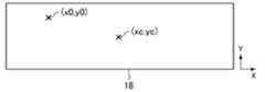
먼저, 상술한 S104에 나타낸 평균 좌표법에 대해서 상세하게 설명한다. 도 6a는 S103에 나타내는 처리에서 확인된 좌표값의 수가 1일 경우의 평균 좌표법의 설명도이다. 도 6b는 S103에 나타내는 처리에서 확인된 좌표값의 수가 5 이상(도 6b의 예에서는 5)일 경우의 평균 좌표법의 설명도이다.First, the average coordinate method shown in S104 will be described in detail. 6A is an explanatory diagram of an average coordinate method when the number of coordinate values confirmed in the process shown in S103 is 1; FIG. 6B is an explanatory diagram of an average coordinate method when the number of coordinate values confirmed in the process shown in S103 is 5 or more (5 in the example of FIG. 6B).
평균 좌표법에서는, 먼저 디스플레이방향 판정부(46)가 상술한 S101에 나타내는 처리에서 방향검출부(34)로부터 접수한 데이터가 나타내는 연직방향을 XY평면의 사영(射影)한 방향과 X축방향이 이루는 예각의 각도를 특정한다. 그리고 디스플레이방향 판정부(46)는 이 각도가 45도 이상일 경우에 정보처리장치(1)가 가로방향으로 쥐어져 있다고 판정하고, 그렇지 않을 경우에 정보처리장치(1)가 세로방향으로 쥐어져 있다고 판정한다. 또한 도 6a 및 도 6b의 예에서는 정보처리장치(1)가 가로방향으로 쥐어져 있다고 판정된 것으로 한다.In the average coordinate method, first, the display
도 4b 또는 도 4d에 도시한 바와 같이 정보처리장치(1)가 세로방향으로 쥐어져 있는 경우는 X축방향이 연직방향을 향할 가능성이 높다. 반대로 도 4a 또는 도 4c에 도시한 바와 같이 정보처리장치(1)가 가로방향으로 쥐어져 있는 경우는 Y축방향이 연직방향을 향할 가능성이 높다. 이것으로 인해 상술한 바와 같이 본 실시형태에서의 평균 좌표법에서는 연직방향과 X축방향이 이루는 각도에 기초하여 정보처리장치(1)가 세로방향으로 쥐어져 있는지, 가로방향으로 쥐어져 있는지가 판정되게 된다.As shown in FIG. 4B or 4D, when the
그리고 쥔 손 판정부(42)는 S103에 나타내는 처리에서 확인된 좌표값의 수가 1(도 6a의 예에서 좌표값은 (x0,y0))일 경우에는 그 좌표값 중 X좌표값 x0과, 배면 터치센서(18)의 중심(좌표값은 (xc,yc))의 X좌표값 xc의 차분 (x0-xc)가 0 또는 양인지, 음인지를 판정한다.When the number of coordinate values confirmed in the process shown in S103 is 1 (the coordinate value is (x0, y0) in the example of Fig. 6A), the
또 쥔 손 판정부(42)는 S103에 나타내는 처리에서 확인된 좌표값의 수가 5 이상(도 6b의 예에서는 각각의 좌표값은 (x0,y0), (x1,y1), (x2,y2), (x3,y3), (x4,y4))일 경우에는 그들의 좌표값이 나타내는 위치군의 중심(좌표값은 (xa,ya). 또한 xa=(x0+x1+x2+x3+x4)/5,ya=(y0+y1+y2+y3+y4)/5))의 X좌표값 xa와, 배면 터치센서(18)의 중심의 X좌표값 xc의 차분 (xa-xc)가 0 또는 양인지, 음인지를 판정한다.6 (the coordinate values of each coordinate value are (x0, y0), (x1, y1), (x2, y2) in the example of Fig. 6B) x0 + x1 + x2 + x3 + x4 + x2 + x3 + x4 + x4 + y4) (Xa-xc) between the X coordinate value xa of the
그리고 쥔 손 판정부(42)는 정보처리장치(1)가 가로방향으로 쥐어져 있다고 판정되었을 때에 (x0-xc)의 값이나 (xa-xc)의 값이 0 또는 양일 경우는 상술한 좌우 플래그의 값을 "우"로 특정하고, 음일 경우는 상술한 좌우 플래그의 값을 "좌"로 특정한다. 한편, 쥔 손 판정부(42)는 정보처리장치(1)가 세로방향으로 쥐어져 있다고 판정되었을 때에 (x0-xc)의 값이나 (xa-xc)의 값이 0 또는 양일 경우는 상술한 좌우 플래그의 값을 "좌"로 특정하고, 음일 경우는 상술한 좌우 플래그의 값을 "우"로 특정한다. 도 6a의 예에서는 (x0-xc)의 값은 음이므로 상술한 좌우 플래그의 값은 "좌"로 특정된다. 도 6b의 예에서는 (xa-xc)의 값은 양이므로 상술한 좌우 플래그의 값은 "우"로 특정된다.When the value of (x0-xc) or the value of (xa-xc) is 0 or positive when it is determined that the
상술한 바와 같이 본 실시형태에서는 평균 좌표법에 있어서 검출된 위치 또는 검출된 위치의 중심 위치가 하우징(10)의 정면에서 봤을 때 배면 터치센서(18)의 중심보다 왼쪽에 있는지 오른쪽에 있는지에 따라서 좌우 플래그의 값을 특정하고 있다.As described above, according to the present embodiment, depending on whether the detected position in the average coordinate method or the center position of the detected position is on the left or right side of the center of the rear
또 본 실시형태에서의 평균 좌표법에서는 정보처리장치(1)가 가로방향으로 쥐어져 있는 경우에는, 정보처리장치(1)가 왼손으로 쥐어지면 도 4a에 도시한 바와 같이 검출된 위치 또는 검출된 위치의 중심 위치가 하우징(10)의 정면에서 봤을 때 배면 터치센서(18)의 중심보다 왼쪽에 있을 가능성이 높다는 생각에 기초하여 (x0-xc)나 (xa-xc)가 음일 경우에 좌우 플래그의 값이 "좌"라고 판정된다. 한편, 오른손으로 쥐어지면 도 4c에 도시한 바와 같이 검출된 위치 또는 검출된 위치의 중심 위치가 하우징(10)의 정면에서 봤을 때 배면 터치센서(18)의 중심보다 오른쪽에 있을 가능성이 높다는 생각에 기초하여 (x0-xc)나 (xa-xc)가 0 또는 양일 경우에 좌우 플래그의 값이 "우"라고 판정된다.In the mean coordinate method in the present embodiment, when the
반대로 정보처리장치(1)가 세로방향으로 쥐어져 있는 경우에는, 정보처리장치(1)가 왼손으로 쥐어지면 도 4b에 도시한 바와 같이 검출된 위치 또는 검출된 위치의 중심 위치가 배면 터치센서(18)의 중심보다 오른쪽에 있을 가능성이 높다는 생각에 기초하여 (x0-xc)나 (xa-xc)가 0 또는 양일 경우에 좌우 플래그의 값이 "좌"라고 판정된다. 한편, 정보처리장치(1)가 오른손으로 쥐어지면 도 4d에 도시한 바와 같이 검출된 위치 또는 검출된 위치의 중심 위치가 배면 터치센서(18)의 중심보다 왼쪽에 있을 가능성이 높다는 생각에 기초하여 (x0-xc)나 (xa-xc)가 음일 경우에 좌우 플래그의 값이 "좌"라고 판정된다.Conversely, when the
다음으로 상술한 S105에 나타낸 벡터 그레디언트법에 대해서 설명한다. 도 6c는 벡터 그레디언트법의 설명도이다.Next, the vector gradient method shown in S105 will be described. 6C is an explanatory diagram of the vector gradient method.
여기에서는 상술한 S102에 나타내는 처리에서 생성된 리스트를 구성하는 2개의 좌표값을 각각 (x0,y0), (x1,y1)로 한다(y0<y1). 벡터 그레디언트법에서는 쥔 손 판정부(42)는 x1-x0의 값이 양 또는 0일 경우에 상술한 좌우 플래그의 값을 "우"로 특정하고, 그렇지 않은 경우에 상술한 좌우 플래그의 값을 "좌"로 특정한다. 도 6c의 예에서는 x1-x0의 값은 음이 되므로 상술한 좌우 플래그의 값은 "좌"로 특정된다.Here, the two coordinate values constituting the list generated in the process shown in S102 are respectively (x0, y0) and (x1, y1) (y0 < y1). In the vector gradient method, the
본 실시형태에서의 벡터 그레디언트법에서는 정보처리장치(1)가 왼손으로 쥐어지면 검출된 2개의 위치가 하우징(10)의 정면에서 봤을 때 좌측 위에서 우측 아래를 향해 나열될 가능성이 높다(특히 집게손가락이 상측면의 버튼(20)에 닿아 있는 경우에는 그 가능성이 높다)는 생각에 기초하여 x1-x0의 값이 음일 경우에 좌우 플래그의 값이 "좌"라고 판정된다. 반대로, 정보처리장치(1)가 오른손으로 쥐어지면 검출된 2개의 위치가 하우징(10)의 정면에서 봤을 때 우측 위에서 좌측 아래를 향해 나열될 가능성이 높다(특히 집게손가락이 상측면의 버튼(20)에 닿아 있는 경우에는 그 가능성이 높다)는 생각에 기초하여 x1-x0의 값이 0 또는 양일 경우에 좌우 플래그의 값이 "우"라고 판정된다.In the vector gradient method according to the present embodiment, when the
다음으로 상술한 S105에 나타낸 벡터 외적법에 대해서 설명한다. 도 6d는 S103에 나타내는 처리에서 확인된 좌표값의 수가 3일 경우의 벡터 외적법의 설명도이다. 도 6e는 S103에 나타내는 처리에서 확인된 좌표값의 수가 4일 경우의 벡터 외적법의 설명도이다.Next, the vector external method shown in S105 will be described. 6D is an explanatory diagram of the vector external method when the number of coordinate values confirmed in the process shown in S103 is three. FIG. 6E is an explanatory diagram of the vector external method when the number of coordinate values confirmed in the process shown in S103 is 4; FIG.
본 실시형태에서의 벡터 외적법에서는 S103에 나타내는 처리에서 확인된 좌표값의 수가 3일 경우(여기에서는 상술한 S102에 나타내는 처리에서 생성된 리스트를 구성하는 3개의 좌표값을 각각 (x0,y0), (x1,y1), (x2,y2)로 함 (y0<y1<y2)) 쥔 손 판정부(42)는 벡터(x1-x0,y1-y0)과 벡터(x2-x0,y2-y0)의 외적의 값이 양 또는 0일 경우에 상술한 좌우 플래그의 값을 "좌"로 특정하고, 그렇지 않은 경우에 상술한 좌우 플래그의 값을 "우"로 특정한다. 도 6d의 예에서는 벡터(x1-x0,y1-y0)과 벡터(x2-x0,y2-y0)의 외적의 값이 양이므로 상술한 좌우 플래그의 값은 "좌"로 특정된다.In the vector external method according to the present embodiment, when the number of coordinate values confirmed in the process shown in S103 is 3 (here, three coordinate values constituting the list generated in the process shown in S102 are referred to as (x0, y0) (x1-x0, y1-y0) and the vector (x2-x0, y2-y0), (x1, y1) and (x2, y2) Quot; left "when the value of the outer product of the left and right flags is positive or zero, and specifies the value of the left and right flags as" right " In the example of FIG. 6D, the values of the left and right flags are specified as "left" because the values of the extrinsic values of the vectors (x1-x0, y1-y0) and the vectors (x2-x0, y2-y0) are positive.
S103에 나타내는 처리에서 확인된 좌표값의 수가 4일 경우(여기에서는 상술한 S102에 나타내는 처리에서 생성된 리스트를 구성하는 4개의 좌표값을 각각 (x0,y0), (x1,y1), (x2,y2), (x3,y3)으로 함(y0<y1<y2<y3)) 쥔 손 판정부(42)는 벡터((x1+x2)/2-x0,(y1+y2)/2-y0)과 벡터(x3-x0,y3-y0)의 외적의 값이 양 또는 0일 경우에 상술한 좌우 플래그의 값을 "좌"로 특정하고, 그렇지 않은 경우에 상술한 좌우 플래그의 값을 "우"로 특정한다. 도 6e의 예에서는 벡터((x1+x2)/2-x0,(y1+y2)/2-y0)과 벡터(x3-x0,y3-y0)의 외적의 값이 음이므로 상술한 좌우 플래그의 값은 "우"로 특정된다.If the number of coordinate values confirmed in the process shown in S103 is 4 (here, the four coordinate values constituting the list generated in the process shown in S102 are respectively referred to as (x0, y0), (x1, y1) (x1 + x2) / 2-x0, (y1 + y2) / 2-y0 (y1, y2, y3) Quot; left "when the value of the outer product of the vector (x3-x0, y3-y0) is positive or 0 and the value of the left and right flags described above is & ". 6E, the values of the extrinsic values of the vectors ((x1 + x2) / 2-x0, (y1 + y2) / 2-y0) and the vectors x3-x0, y3-y0 are negative, The value is specified as "right".
본 실시형태에서의 벡터 외적법에서는 검출된 위치가 3개일 경우는 정보처리장치(1)가 왼손으로 쥐어지면, 이 3개의 위치들을 위에서부터 순서대로 연결시키면 하우징(10)의 정면에서 봤을 때 오른쪽으로 볼록해질 가능성이 높다는 생각에 기초하여 벡터(x1-x0,y1-y0)과 벡터(x2-x0,y2-y0)의 외적의 값이 양 또는 0일 경우에 좌우 플래그의 값이 "좌"라고 판정된다. 반대로 정보처리장치(1)가 오른손으로 쥐어지면, 상술한 3개의 위치를 위에서부터 순서대로 연결시키면 하우징(10)의 정면에서 봤을 때 왼쪽으로 볼록해질 가능성이 높다는 생각에 기초하여 벡터(x1-x0,y1-y0)과 벡터(x2-x0,y2-y0)의 외적의 값이 음일 경우에 좌우 플래그의 값이 "우"라고 판정된다.In the vector external method according to the present embodiment, when the detected position is three, when the
또 본 실시형태에서의 벡터 외적법에서는 검출된 위치가 4개일 경우는 정보처리장치(1)가 왼손으로 쥐어지면, 가장 위의 위치, 위에서 2번째 위치와 3번째 위치의 중점의 위치, 가장 아래의 위치를 위에서부터 순서대로 연결시키면 하우징(10)의 정면에서 봤을 때 오른쪽으로 볼록해질 가능성이 높다는 생각에 기초하여 벡터((x1+x2)/2-x0,(y1+y2)/2-y0)과 벡터(x3-x0,y3-y0)의 외적의 값이 양 또는 0일 경우에 좌우 플래그의 값이 "좌"라고 판정된다. 반대로 정보처리장치(1)가 오른손으로 쥐어지면, 가장 위의 위치, 위에서 2번째 위치와 3번째 위치의 중점의 위치, 가장 아래의 위치를 위에서부터 순서대로 연결시키면 하우징(10)의 정면에서 봤을 때 왼쪽으로 볼록해질 가능성이 높다는 생각에 기초하여 벡터((x1+x2)/2-x0,(y1+y2)/2-y0)과 벡터(x3-x0,y3-y0)의 외적의 값이 음일 경우에 좌우 플래그의 값이 "우"라고 판정된다.In the vector external method according to the present embodiment, when the detected position is four, when the
그리고 본 실시형태에서는 터치패널(12)에 포함되는 디스플레이(14)에 표시되어 있는 화상을 사용자가 손가락이나 스타일러스로 터치하면 전면 터치센서(16)에 의해 그 위치가 검출되어 그 화상에 따른 정보(예를 들면 그 화상이 나타내는 내용을 표시하는 정보)가 디스플레이(14)에 표시된다. 이때, 정보가 표시되는 위치는 전면 터치센서(16)에 의한 검출위치, 및 상술한 S101∼S109에 나타내는 처리에서의 최근 판정결과에 따라서 변화한다.In the present embodiment, when the user touches the image displayed on the
여기에서 본 실시형태에 따른 정보처리장치(1)에서 실시되는 전면 터치센서(16)가 터치되었을 때의 정보의 표시 처리에 대해서 설명한다.Herein, display processing of information when the
먼저, 영역특정부(48)가 전면 터치센서(16)로부터 검출된 위치의 좌표값(X좌표값 및 Y좌표값)을 접수한다. 그리고 영역특정부(48)는 그 검출위치에 겹치는 디스플레이(14)상의 위치의 좌표값(예를 들면, 그 검출위치와 동일한 X좌표값 및 Y좌표값)을 특정한다. 여기에서는 특정된 위치의 좌표값을 (xq,yq)로 한다. 또 정보처리장치(1)가 가로방향으로 쥐어졌을 경우의 디스플레이(14)의 좌측 아래 모퉁이의 좌표값을 (x0,y0), 디스플레이(14)의 우측 아래 모퉁이의 좌표값을 (x1,y1), 디스플레이(14)의 좌측 위 모퉁이의 좌표값을 (x2,y2), 디스플레이(14)의 우측 위 모퉁이의 좌표값을 (x3,y3)으로 한다.First, the
그리고 상술한 S101∼S109에 나타낸 처리의 최신 판정결과가 왼쪽일 경우에는, 영역특정부(48)는 좌표값(x1,y1)로 표시되는 위치와 좌표값(xq,yq)로 표시되는 위치를 대각선상의 서로 마주 보는 정점으로 하는 직사각형 영역을 금지영역(52)으로 특정하고, 좌표값(x2,y2)로 표시되는 위치와 좌표값(xq,yq)로 표시되는 위치를 대각선상의 서로 마주 보는 정점으로 하는 직사각형 영역을 제1 우선영역(54-1)으로 특정하고, 좌표값(x0,y0)으로 표시되는 위치와 좌표값(xq,yq)로 표시되는 위치를 대각선상의 서로 마주 보는 정점으로 하는 직사각형 영역을 제2 우선영역(54-2)으로 특정하고, 좌표값(x3,y3)으로 표시되는 위치와 좌표값(xq,yq)로 표시되는 위치를 대각선상의 서로 마주 보는 정점으로 하는 직사각형 영역을 제3 우선영역(54-3)으로 특정한다. 도 7a에 상술한 S101∼S109에 나타낸 처리의 최신 판정결과가 오른쪽일 경우의 금지영역(52) 및 우선영역(54)의 일례를 도시한다. 도 7a에서는 금지영역(52)이 사선으로 표시되어 있다.If the latest determination result of the process shown in S101 to S109 is the left, the
한편, 상술한 S101∼S109에 나타낸 처리의 최신 판정결과가 오른쪽일 경우에는 영역특정부(48)는 좌표값(x0,y0)으로 표시되는 위치와 좌표값(xq,yq)로 표시되는 위치를 대각선상의 서로 마주 보는 정점으로 하는 직사각형 영역을 금지영역(52)으로 특정하고, 좌표값(x3,y3)으로 표시되는 위치와 좌표값(xq,yq)로 표시되는 위치를 대각선상의 서로 마주 보는 정점으로 하는 직사각형 영역을 제1 우선영역(54-1)으로 특정하고, 좌표값(x1,y1)로 표시되는 위치와 좌표값(xq,yq)로 표시되는 위치를 대각선상의 서로 마주 보는 정점으로 하는 직사각형 영역을 제2 우선영역(54-2)으로 특정하고, 좌표값(x2,y2)로 표시되는 위치와 좌표값(xq,yq)로 표시되는 위치를 대각선상의 서로 마주 보는 정점으로 하는 직사각형 영역을 제3 우선영역(54-3)으로 특정한다. 도 7b에 상술한 S101∼S109에 나타낸 처리의 최신 판정결과가 왼쪽일 경우의 금지영역(52) 및 우선영역(54)의 일례를 도시한다. 도 7b에서는 금지영역(52)이 사선으로 표시되어 있다.On the other hand, when the latest determination result of the processing shown in S101 to S109 is the right, the
이런 식으로 하여 본 실시형태에서는 배면 터치센서(18)에 의한 검출위치에 기초하여 좌표값(x1,y1)로 표시되는 위치와 좌표값(xq,yq)로 표시되는 위치를 대각선상의 서로 마주 보는 정점으로 하는 직사각형 영역, 및 좌표값(x0,y0)으로 표시되는 위치와 좌표값(xq,yq)로 표시되는 위치를 대각선상의 서로 마주 보는 정점으로 하는 직사각형 영역 중 한쪽이 금지영역(52)으로 특정되게 된다.In this way, in the present embodiment, the position indicated by the coordinate value (x1, y1) and the position indicated by the coordinate value (xq, yq) on the basis of the detection position by the rear
그리고 표시처리 실행부(50)가 표시해야 할 정보를 디스플레이(14)의 제1 우선영역(54-1) 내에 표시 출력시킨다. 또한 여기에서, 표시처리 실행부(50)는 소정의 규칙에 따라서 제1 우선영역(54-1)에 정보를 표시시킬지 여부를 판단하도록 해도 된다. 표시처리 실행부(50)는 예를 들면 제1 우선영역(54-1) 내에 이미 표시되어 있는 정보가 존재할 경우에는 제1 우선영역(54-1) 내에 정보를 표시하지 않는다고 결정하고, 표시해야 할 정보를 제2 우선영역(54-2) 내에 표시 출력시키도록 해도 된다. 또 표시처리 실행부(50)는 마찬가지로, 예를 들면 제2 우선영역(54-2) 내에도 이미 표시되어 있는 정보가 존재할 경우에는 정보를 표시하지 않는다고 결정하고, 표시해야 할 정보를 제3 우선영역(54-3) 내에 표시 출력시키도록 해도 된다. 또 표시처리 실행부(50)는 표시해야 할 정보가 복수 존재할 경우에 이 정보들을 각각 제1 우선영역(54-1) 내, 및 제2 우선영역(54-2) 내에 표시 출력시키도록 해도 된다.Then, the display
상기와 같이 본 실시형태에 따르면 배면 터치센서(18)에 의한 검출위치에 기초하여 정보처리장치(1)가 왼손으로 쥐어져 있다고 판단되었을 때에는 전면 터치센서(16)를 조작하는 오른손에 의해 가려질 가능성이 높은 디스플레이(14)의 우측 아래의 영역이 금지영역(52)으로 설정되고, 정보처리장치(1)가 오른손으로 쥐어져 있다고 판단되었을 때에는 전면 터치센서(16)를 조작하는 왼손에 의해 가려질 가능성이 높은 디스플레이(14)의 좌측 아래의 영역이 금지영역(52)으로 설정된다. 그리고 본 실시형태에서는 디스플레이(14) 내의 금지영역(52) 이외의 영역에 표시 대상의 정보가 표시되므로 사용자가 보기 힘든 위치에 표시 대상의 정보가 표시되는 것을 막을 수 있게 된다.As described above, according to the present embodiment, when it is determined that the
또한 본 발명은 상술한 실시형태에 한정되는 것이 아니다.The present invention is not limited to the above-described embodiments.
예를 들면 배면 터치센서(18)에서 검출된 좌표값의 수와, 좌우 플래그의 값의 판정방법의 대응 관계는 상술한 것에는 한정되지 않는다. 예를 들면 쥔 손 판정부(42)는 2개 이상의 판정방법에 의한 판정결과의 조합에 기초하여 좌우 플래그의 값을 결정하도록 해도 된다. 구체적으로는, 예를 들면 배면 터치센서(18)에서 검출된 좌표값의 수가 2일 경우에 쥔 손 판정부(42)는 상술한 벡터 그레디언트법에 의해 특정되는 좌우 플래그의 값과, 이들 2개의 좌표값의 중점이 디스플레이(14)의 중심보다 왼쪽에 있는지 오른쪽에 있는지에 기초하는 상술한 평균 좌표법에 의해 특정되는 좌우 플래그의 값이 일치할 경우에, 그 값을 좌우 플래그의 값으로서 결정하고, 그렇지 않을 경우는 판정 불가라고 결정하도록 해도 된다.For example, the correspondence relationship between the number of coordinate values detected by the rear
또 금지영역(52)의 설정 방법은 상술한 실시형태에는 한정되지 않는다. 예를 들면 디스플레이(14) 내의 소정의 2개의 영역이 금지영역(52)의 후보로서 미리 설정되어 있어도 된다. 보다 구체적으로는, 예를 들면 디스플레이(14)의 좌측 아래 모퉁이를 중심으로 하는 소정 반경의 사분의 일원(一圓), 및 디스플레이(14)의 우측 아래 모퉁이를 중심으로 하는 소정 반경의 사분의 일원이 금지영역(52)의 후보로서 미리 설정되어 있어도 된다. 그리고 영역특정부(48)는 상술한 S101∼S109에 나타낸 처리의 최신 판정결과가 왼쪽일 경우는 우측의 금지영역(52)의 후보를 금지영역(52)으로 특정하고, 상술한 S101∼S109에 나타낸 처리의 최신 판정결과가 오른쪽일 경우는 좌측의 금지영역(52)의 후보를 금지영역(52)으로 특정하도록 해도 된다.The setting method of the forbidden
또 예를 들면 쥔 손 판정부(42)는 배면 터치센서(18)에서 검출된 좌표값의 수가 6 이상일 경우는, 정보처리장치(1)는 양손으로 쥐어져 있다고 판정하도록 해도 된다. 이때는 영역특정부(48)가 디스플레이(14) 내에 금지영역(52)을 설정하지 않고, 디스플레이(14)를 상중하의 3개 영역으로 분할한 각 영역을 위에서부터 순서대로 제1 우선영역(54-1), 제2 우선영역(54-2), 제3 우선영역(54-3)으로 특정하도록 해도 된다.For example, when the number of coordinate values detected by the rear
또 쥔 손 판정부(42)는 좌우 플래그의 값을 배면 터치센서(18)에서 검출된 좌표값(또는 배면 터치센서(18)에서 검출된 복수 위치의 중심의 좌표값)에 관련지어서 좌우 플래그 유지부(44)에 유지시키도록 해도 된다. 그리고 정보처리장치(1)가 상술한 평균 좌표법에 의해 좌우 플래그의 값을 판정할 때에 값이 "좌"인 좌우 플래그에 관련되어 있는 X좌표값의 평균치가, 값이 "우"인 좌우 플래그에 관련되어 있는 X좌표값의 평균치보다도 작을 경우에는 정보처리장치(1)가 가로방향으로 쥐어져 있다고 판정하고, 그렇지 않은 경우에는 정보처리장치(1)가 세로방향으로 쥐어져 있다고 판정하도록 해도 된다.Further, the gripping
또 상술한 실시형태와 같이 쥔 손 판정부(42)는 상술한 S104∼S107에서의 과거의 판정결과의 이력에 기초하여 정보처리장치(1)를 쥐고 있는 손을 판정할 필요는 없고, 배면 터치센서(18)의 최신 검출위치에 기초하여 정보처리장치(1)를 쥐고 있는 손을 판정하도록 해도 된다.The
Claims (11)
Translated fromKorean상기 표시부에 겹쳐서 배치되어 있는, 검출면상에서의 물체의 위치를 검출하는 전면 터치센서와,
상기 전면 터치센서에 대향하여 배치되는, 검출면상에서의 물체의 위치를 검출하는 배면 터치센서와,
제어부를 구비하고,
상기 제어부는,
상기 배면 터치센서에 의한 적어도 하나의 검출위치가, 상기 전면 터치센서의 좌측(또는 우측) 절반에 대향하는 상기 배면 터치센서 내의 영역 내에 존재하면 전면 터치센서의 우측(또는 좌측) 절반에 해당하는 영역을 금지영역으로서 특정하고,
표시 대상이 되는 정보를 상기 표시부 내의 상기 금지영역 이외의 영역에 표시시키는 것을 특징으로 하는 정보처리장치.A display section,
A front touch sensor which detects the position of an object on the detection surface,
A rear surface touch sensor disposed opposite to the front surface touch sensor for detecting a position of an object on the detection surface,
And a control unit,
Wherein,
If at least one detection position by the rear touch sensor exists in an area within the rear touch sensor facing the left (or right) half of the front touch sensor, the area corresponding to the right (or left) half of the front touch sensor As a prohibited area,
And displays information to be displayed on an area other than the forbidden area in the display section.
상기 표시부의 짧은 길이방향이 연직(鉛直)방향을 따른 방향인지, 상기 표시부의 긴 길이방향이 연직방향을 따른 방향인지에 따라서 상기 배면 터치센서에 의한 검출위치와, 상기 특정되는 금지영역의 대응 관계가 역전되는 것을 특징으로 하는 정보처리장치.The method according to claim 1,
The detection position detected by the rear surface touch sensor and the correspondence relationship between the specified prohibited area and the detection position detected by the rear touch sensor in accordance with whether the short length direction of the display unit is along the vertical direction or the long length direction of the display unit is along the vertical direction, Is reversed.
상기 표시부의 방향을 검출하는 방향검출부를 더 구비하고,
상기 제어부는,
상기 방향검출부에 의한 검출결과에 기초하여 상기 표시부의 긴 길이방향이 연직방향을 따른 방향인지, 상기 표시부의 짧은 길이방향이 연직방향을 따른 방향인지를 판정하여,
상기 표시부의 짧은 길이방향이 연직방향을 따른 방향이라고 판정될 때에는 상기 배면 터치센서에 의한 적어도 하나의 검출위치가, 상기 전면 터치센서의 좌측(또는 우측) 절반에 대향하는 상기 배면 터치센서 내의 영역 내에 존재하면 전면 터치센서의 우측(또는 좌측) 절반에 해당하는 영역을 상기 금지영역으로서 특정하며,
상기 표시부의 긴 길이방향이 연직방향을 따른 방향이라고 판정될 때에는 상기 배면 터치센서에 의한 적어도 하나의 검출위치가, 상기 전면 터치센서의 좌측(또는 우측) 절반에 대향하는 상기 배면 터치센서 내의 영역 내에 존재하면 전면 터치센서의 좌측(또는 우측) 절반에 해당하는 영역을 상기 금지영역으로서 특정하는 것을 특징으로 하는 정보처리장치.3. The method according to claim 1 or 2,
Further comprising a direction detecting section for detecting a direction of the display section,
Wherein,
It is determined whether the long length direction of the display unit is a direction along the vertical direction or the short length direction of the display unit is a direction along the vertical direction based on the detection result by the direction detection unit,
When the short length direction of the display unit is determined to be the direction along the vertical direction, at least one detection position by the rear surface touch sensor is within a region within the rear touch sensor opposed to the left (or right) half of the front touch sensor (Or left) half of the front touch sensor as the forbidden area if it exists,
When at least one detection position by the rear surface touch sensor is detected within a region within the rear surface touch sensor opposed to the left (or right) half of the front surface touch sensor when it is determined that the longitudinal direction of the display unit is a direction along the vertical direction (Or right) half of the front touch sensor as the forbidden area if it exists.
상기 제어부는, 상기 전면 터치센서에 의한 검출위치에 기초하여 상기 특정되는 금지영역의 위치를 결정하는 것을 특징으로 하는 정보처리장치.3. The method according to claim 1 or 2,
Wherein the control unit determines the position of the specified forbidden area based on the detection position of the front touch sensor.
상기 제어부는, 상기 전면 터치센서에 의한 검출위치의 좌측 아래에 위치하는 상기 표시부 내의 영역을 상기 특정되는 금지영역 중 좌측 영역으로서 결정하고, 상기 전면 터치센서에 의한 검출위치의 우측 아래에 위치하는 상기 표시부 내의 영역을 상기 특정되는 금지영역 중 우측 영역으로서 결정하는 것을 특징으로 하는 정보처리장치.The method according to claim 6,
Wherein the control unit determines an area in the display unit located at the lower left of the detection position by the front touch sensor as a left area of the specified prohibited area, And determines an area in the display unit as a right area of the specified prohibited area.
상기 제어부는, 표시 대상이 되는 정보가 복수 존재하고, 상기 복수의 정보가 순서지어져 있는 경우에, 상기 표시부 내의 상기 금지영역 이외의 영역을 분할한 복수의 순서지어진 영역 내에, 상기 순서지어진 복수의 정보를, 정보의 순서와 영역의 순서가 대응하도록 분할된 각 영역에 표시시키는 것을 특징으로 하는 정보처리장치.3. The method according to claim 1 or 2,
Wherein the control unit is operable to display a plurality of ordered information items in a plurality of ordered areas obtained by dividing an area other than the forbidden area in the display unit in a case where a plurality of pieces of information to be displayed exist and the plurality of pieces of information are ordered Is displayed in each divided area so that the order of the information and the order of the area correspond to each other.
상기 배면 터치센서에 의한 적어도 하나의 검출위치가, 상기 전면 터치센서의 좌측(또는 우측) 절반에 대향하는 상기 배면 터치센서 내의 영역 내에 존재하면 전면 터치센서의 우측(또는 좌측) 절반에 해당하는 영역을 금지영역으로서 특정하고,
표시 대상이 되는 정보를 상기 표시부 내의 상기 금지영역 이외의 영역에 표시시키는 것을 특징으로 하는 정보처리장치의 제어방법.A front touch sensor for detecting the position of an object on the detection surface and disposed so as to overlap with the display unit; and a rear surface touch sensor for detecting the position of an object on the detection surface, A control method for an information processing apparatus,
If at least one detection position by the rear touch sensor exists in an area within the rear touch sensor facing the left (or right) half of the front touch sensor, the area corresponding to the right (or left) half of the front touch sensor As a prohibited area,
And the information to be displayed is displayed in an area other than the forbidden area in the display section.
상기 배면 터치센서에 의한 적어도 하나의 검출위치가, 상기 전면 터치센서의 좌측(또는 우측) 절반에 대향하는 상기 배면 터치센서 내의 영역 내에 존재하면 전면 터치센서의 우측(또는 좌측) 절반에 해당하는 영역을 금지영역으로서 특정하는 순서와,
표시 대상이 되는 정보를 상기 표시부 내의 특정된 금지영역 이외의 영역에 표시시키는 순서를 실행시키는 것을 특징으로 하는 프로그램을 기억한 컴퓨터 판독 가능한 정보기억 매체.A front touch sensor for detecting the position of an object on the detection surface and disposed so as to overlap with the display unit; and a rear surface touch sensor for detecting the position of an object on the detection surface, The information processing apparatus includes:
If at least one detection position by the rear touch sensor exists in an area within the rear touch sensor facing the left (or right) half of the front touch sensor, the area corresponding to the right (or left) half of the front touch sensor As a forbidden area,
And displaying the information to be displayed on an area other than the specified forbidden area in the display unit.
Applications Claiming Priority (3)
| Application Number | Priority Date | Filing Date | Title |
|---|---|---|---|
| JPJP-P-2011-112157 | 2011-05-19 | ||
| JP2011112157AJP5594847B2 (en) | 2011-05-19 | 2011-05-19 | Information processing apparatus, information processing apparatus control method, program, and information storage medium |
| PCT/JP2012/059518WO2012157367A1 (en) | 2011-05-19 | 2012-04-06 | Information processing device, method for controlling information processing device, program, and information recording medium |
Publications (2)
| Publication Number | Publication Date |
|---|---|
| KR20140009481A KR20140009481A (en) | 2014-01-22 |
| KR101524176B1true KR101524176B1 (en) | 2015-05-29 |
Family
ID=47176708
Family Applications (1)
| Application Number | Title | Priority Date | Filing Date |
|---|---|---|---|
| KR1020137029858AActiveKR101524176B1 (en) | 2011-05-19 | 2012-04-06 | Information processing device, method for controlling information processing device, program, and information recording medium |
Country Status (8)
| Country | Link |
|---|---|
| US (1) | US20140092048A1 (en) |
| EP (1) | EP2711813B1 (en) |
| JP (1) | JP5594847B2 (en) |
| KR (1) | KR101524176B1 (en) |
| CN (1) | CN103518177B (en) |
| BR (1) | BR112013029660A2 (en) |
| RU (1) | RU2606048C2 (en) |
| WO (1) | WO2012157367A1 (en) |
Families Citing this family (9)
| Publication number | Priority date | Publication date | Assignee | Title |
|---|---|---|---|---|
| JP5909914B2 (en) | 2011-08-05 | 2016-04-27 | セイコーエプソン株式会社 | Actuator, optical scanner and image forming apparatus |
| JP2014126949A (en)* | 2012-12-25 | 2014-07-07 | Kyocera Corp | Portable terminal equipment, screen control method and program |
| US9671828B2 (en) | 2014-09-19 | 2017-06-06 | Lg Electronics Inc. | Mobile terminal with dual touch sensors located on different sides of terminal body and method of controlling the same |
| KR20160114413A (en)* | 2015-03-24 | 2016-10-05 | 엘지전자 주식회사 | Mobile terminal and control method for the mobile terminal |
| WO2018037738A1 (en)* | 2016-08-24 | 2018-03-01 | ソニー株式会社 | Information processing device, program, and information processing system |
| TWI602099B (en)* | 2016-10-21 | 2017-10-11 | 鹽光股份有限公司 | Capacitive Sensor Device And Detecting Method For A Touch event in A Conductive Matter Thereon |
| JP6389581B1 (en)* | 2018-05-16 | 2018-09-12 | 株式会社Cygames | Program, electronic apparatus, and method |
| CN110793719A (en)* | 2019-12-06 | 2020-02-14 | 福州聚英智能科技有限公司 | Latent AGV gravity center detection device and method for identifying and preventing dumping risks |
| JP7726089B2 (en)* | 2022-02-15 | 2025-08-20 | セイコーエプソン株式会社 | Display method and display device |
Citations (1)
| Publication number | Priority date | Publication date | Assignee | Title |
|---|---|---|---|---|
| JP2010108071A (en)* | 2008-10-28 | 2010-05-13 | Fujifilm Corp | Image display device, image display method and program |
Family Cites Families (16)
| Publication number | Priority date | Publication date | Assignee | Title |
|---|---|---|---|---|
| US7800592B2 (en)* | 2005-03-04 | 2010-09-21 | Apple Inc. | Hand held electronic device with multiple touch sensing devices |
| JP3852368B2 (en) | 2002-05-16 | 2006-11-29 | ソニー株式会社 | Input method and data processing apparatus |
| US20060084482A1 (en)* | 2004-10-15 | 2006-04-20 | Nokia Corporation | Electronic hand-held device with a back cover keypad and a related method |
| JP4569411B2 (en)* | 2005-08-03 | 2010-10-27 | 日本電気株式会社 | Mobile device |
| EP1971116B1 (en)* | 2006-03-31 | 2017-09-13 | Drnc Holdings, Inc. | Mobile phone with sensor for detection of user's handling |
| US8988359B2 (en)* | 2007-06-19 | 2015-03-24 | Nokia Corporation | Moving buttons |
| US8116831B2 (en)* | 2007-11-29 | 2012-02-14 | Motorola Mobility, Inc. | Hand-held communication device with auxiliary input apparatus, and method |
| US9513765B2 (en)* | 2007-12-07 | 2016-12-06 | Sony Corporation | Three-dimensional sliding object arrangement method and system |
| KR101499546B1 (en)* | 2008-01-17 | 2015-03-09 | 삼성전자주식회사 | Method and apparatus for controlling display area in touch screen device, and computer readable medium thereof |
| JP2010113503A (en)* | 2008-11-06 | 2010-05-20 | Sharp Corp | Mobile terminal device |
| JP2010140329A (en)* | 2008-12-12 | 2010-06-24 | Sharp Corp | Display device, display method, and display program |
| EP2360560A1 (en)* | 2008-12-16 | 2011-08-24 | NEC Corporation | Mobile terminal device and key arrangement control method |
| JP2010154090A (en)* | 2008-12-24 | 2010-07-08 | Toshiba Corp | Mobile terminal |
| JP4714279B2 (en)* | 2009-02-25 | 2011-06-29 | 株式会社コナミデジタルエンタテインメント | Portable information processing apparatus, processing method, and program |
| JP5303785B2 (en)* | 2009-05-12 | 2013-10-02 | シャープ株式会社 | Display device, display method, and display program |
| JP2011028560A (en)* | 2009-07-27 | 2011-02-10 | Sony Corp | Information processing apparatus, display method, and display program |
- 2011
- 2011-05-19JPJP2011112157Apatent/JP5594847B2/enactiveActive
- 2012
- 2012-04-06BRBR112013029660-7Apatent/BR112013029660A2/ennot_activeApplication Discontinuation
- 2012-04-06WOPCT/JP2012/059518patent/WO2012157367A1/enactiveApplication Filing
- 2012-04-06RURU2013156454Apatent/RU2606048C2/enactive
- 2012-04-06KRKR1020137029858Apatent/KR101524176B1/enactiveActive
- 2012-04-06USUS14/118,241patent/US20140092048A1/ennot_activeAbandoned
- 2012-04-06EPEP12785357.0Apatent/EP2711813B1/enactiveActive
- 2012-04-06CNCN201280023077.XApatent/CN103518177B/enactiveActive
Patent Citations (1)
| Publication number | Priority date | Publication date | Assignee | Title |
|---|---|---|---|---|
| JP2010108071A (en)* | 2008-10-28 | 2010-05-13 | Fujifilm Corp | Image display device, image display method and program |
Also Published As
| Publication number | Publication date |
|---|---|
| CN103518177B (en) | 2016-10-12 |
| JP2012243066A (en) | 2012-12-10 |
| KR20140009481A (en) | 2014-01-22 |
| CN103518177A (en) | 2014-01-15 |
| WO2012157367A1 (en) | 2012-11-22 |
| JP5594847B2 (en) | 2014-09-24 |
| RU2606048C2 (en) | 2017-01-10 |
| RU2013156454A (en) | 2015-06-27 |
| EP2711813B1 (en) | 2020-08-05 |
| BR112013029660A2 (en) | 2020-08-04 |
| EP2711813A4 (en) | 2015-02-25 |
| EP2711813A1 (en) | 2014-03-26 |
| US20140092048A1 (en) | 2014-04-03 |
Similar Documents
| Publication | Publication Date | Title |
|---|---|---|
| KR101524176B1 (en) | Information processing device, method for controlling information processing device, program, and information recording medium | |
| JP5205157B2 (en) | Portable image display device, control method thereof, program, and information storage medium | |
| JP5529700B2 (en) | Information processing apparatus, control method thereof, and program | |
| US8854320B2 (en) | Mobile type image display device, method for controlling the same and information memory medium | |
| JP5705885B2 (en) | Input display device | |
| KR101484916B1 (en) | A digitizer improving the accuracy in positioning | |
| CN103914207A (en) | Terminal and method for operating the same | |
| CN111352524B (en) | Information input device | |
| JP5827695B2 (en) | Information processing apparatus, information processing method, program, and information storage medium | |
| JP2014197334A (en) | Display control device, control method of the same, and control program | |
| KR20140106285A (en) | Portable display device | |
| KR101598807B1 (en) | Method and digitizer for measuring slope of a pen | |
| JP5692796B2 (en) | Information terminal, input method and program | |
| JP5841023B2 (en) | Information processing apparatus, information processing method, program, and information storage medium | |
| CN102129315A (en) | Operation input device | |
| JP2013037481A (en) | Input device, information processing device, input control method, and program | |
| US20150070288A1 (en) | Method and apparatus for providing 3d input | |
| JP2013058024A (en) | Mobile terminal, input reception method, and program |
Legal Events
| Date | Code | Title | Description |
|---|---|---|---|
| A201 | Request for examination | ||
| PA0105 | International application | Patent event date:20131111 Patent event code:PA01051R01D Comment text:International Patent Application | |
| PA0201 | Request for examination | ||
| AMND | Amendment | ||
| PG1501 | Laying open of application | ||
| E902 | Notification of reason for refusal | ||
| PE0902 | Notice of grounds for rejection | Comment text:Notification of reason for refusal Patent event date:20140930 Patent event code:PE09021S01D | |
| AMND | Amendment | ||
| E601 | Decision to refuse application | ||
| PE0601 | Decision on rejection of patent | Patent event date:20150327 Comment text:Decision to Refuse Application Patent event code:PE06012S01D Patent event date:20140930 Comment text:Notification of reason for refusal Patent event code:PE06011S01I | |
| AMND | Amendment | ||
| PX0901 | Re-examination | Patent event code:PX09011S01I Patent event date:20150327 Comment text:Decision to Refuse Application Patent event code:PX09012R01I Patent event date:20141028 Comment text:Amendment to Specification, etc. Patent event code:PX09012R01I Patent event date:20131112 Comment text:Amendment to Specification, etc. | |
| PX0701 | Decision of registration after re-examination | Patent event date:20150521 Comment text:Decision to Grant Registration Patent event code:PX07013S01D Patent event date:20150429 Comment text:Amendment to Specification, etc. Patent event code:PX07012R01I Patent event date:20150327 Comment text:Decision to Refuse Application Patent event code:PX07011S01I Patent event date:20141028 Comment text:Amendment to Specification, etc. Patent event code:PX07012R01I Patent event date:20131112 Comment text:Amendment to Specification, etc. Patent event code:PX07012R01I | |
| X701 | Decision to grant (after re-examination) | ||
| GRNT | Written decision to grant | ||
| PR0701 | Registration of establishment | Comment text:Registration of Establishment Patent event date:20150522 Patent event code:PR07011E01D | |
| PR1002 | Payment of registration fee | Payment date:20150526 End annual number:3 Start annual number:1 | |
| PG1601 | Publication of registration | ||
| FPAY | Annual fee payment | Payment date:20180503 Year of fee payment:4 | |
| PR1001 | Payment of annual fee | Payment date:20180503 Start annual number:4 End annual number:4 | |
| FPAY | Annual fee payment | Payment date:20190503 Year of fee payment:5 | |
| PR1001 | Payment of annual fee | Payment date:20190503 Start annual number:5 End annual number:5 | |
| PR1001 | Payment of annual fee | Payment date:20200506 Start annual number:6 End annual number:6 | |
| PR1001 | Payment of annual fee | Payment date:20210429 Start annual number:7 End annual number:7 | |
| PR1001 | Payment of annual fee | Payment date:20240424 Start annual number:10 End annual number:10 |