KR101523237B1 - Injection device for delivering a medication - Google Patents
Injection device for delivering a medicationDownload PDFInfo
- Publication number
- KR101523237B1 KR101523237B1KR1020097021401AKR20097021401AKR101523237B1KR 101523237 B1KR101523237 B1KR 101523237B1KR 1020097021401 AKR1020097021401 AKR 1020097021401AKR 20097021401 AKR20097021401 AKR 20097021401AKR 101523237 B1KR101523237 B1KR 101523237B1
- Authority
- KR
- South Korea
- Prior art keywords
- insertion sleeve
- sleeve
- surface area
- scanning device
- raised surface
- Prior art date
- Legal status (The legal status is an assumption and is not a legal conclusion. Google has not performed a legal analysis and makes no representation as to the accuracy of the status listed.)
- Active
Links
- 239000003814drugSubstances0.000titleclaimsabstractdescription9
- 229940079593drugDrugs0.000titleclaimsabstractdescription6
- 238000002347injectionMethods0.000titleabstractdescription3
- 239000007924injectionSubstances0.000titleabstractdescription3
- 238000003780insertionMethods0.000claimsabstractdescription105
- 230000037431insertionEffects0.000claimsabstractdescription105
- 238000002360preparation methodMethods0.000claimsdescription29
- 210000002105tongueAnatomy0.000claimsdescription15
- 238000000034methodMethods0.000claimsdescription13
- 230000000694effectsEffects0.000claimsdescription8
- 239000011521glassSubstances0.000claimsdescription8
- 239000000126substanceSubstances0.000claimsdescription5
- 238000007789sealingMethods0.000claimsdescription3
- 238000007639printingMethods0.000description4
- 238000003475laminationMethods0.000description3
- 239000000243solutionSubstances0.000description3
- 239000000356contaminantSubstances0.000description2
- 238000011109contaminationMethods0.000description2
- 230000001419dependent effectEffects0.000description2
- 238000009826distributionMethods0.000description2
- 238000004519manufacturing processMethods0.000description2
- 238000005520cutting processMethods0.000description1
- 238000010586diagramMethods0.000description1
- 238000012377drug deliveryMethods0.000description1
- 239000000839emulsionSubstances0.000description1
- 238000005530etchingMethods0.000description1
- 230000008014freezingEffects0.000description1
- 238000007710freezingMethods0.000description1
- 229940124508injectable medicineDrugs0.000description1
- 238000010030laminatingMethods0.000description1
- 230000013011matingEffects0.000description1
- 239000000725suspensionSubstances0.000description1
Images


Classifications
- A—HUMAN NECESSITIES
- A61—MEDICAL OR VETERINARY SCIENCE; HYGIENE
- A61M—DEVICES FOR INTRODUCING MEDIA INTO, OR ONTO, THE BODY; DEVICES FOR TRANSDUCING BODY MEDIA OR FOR TAKING MEDIA FROM THE BODY; DEVICES FOR PRODUCING OR ENDING SLEEP OR STUPOR
- A61M5/00—Devices for bringing media into the body in a subcutaneous, intra-vascular or intramuscular way; Accessories therefor, e.g. filling or cleaning devices, arm-rests
- A61M5/178—Syringes
- A61M5/31—Details
- A61M5/315—Pistons; Piston-rods; Guiding, blocking or restricting the movement of the rod or piston; Appliances on the rod for facilitating dosing ; Dosing mechanisms
- A61M5/31533—Dosing mechanisms, i.e. setting a dose
- A61M5/31545—Setting modes for dosing
- A61M5/31548—Mechanically operated dose setting member
- A61M5/3155—Mechanically operated dose setting member by rotational movement of dose setting member, e.g. during setting or filling of a syringe
- A61M5/31551—Mechanically operated dose setting member by rotational movement of dose setting member, e.g. during setting or filling of a syringe including axial movement of dose setting member
- A—HUMAN NECESSITIES
- A61—MEDICAL OR VETERINARY SCIENCE; HYGIENE
- A61M—DEVICES FOR INTRODUCING MEDIA INTO, OR ONTO, THE BODY; DEVICES FOR TRANSDUCING BODY MEDIA OR FOR TAKING MEDIA FROM THE BODY; DEVICES FOR PRODUCING OR ENDING SLEEP OR STUPOR
- A61M5/00—Devices for bringing media into the body in a subcutaneous, intra-vascular or intramuscular way; Accessories therefor, e.g. filling or cleaning devices, arm-rests
- A61M5/178—Syringes
- A61M5/31—Details
- A61M5/315—Pistons; Piston-rods; Guiding, blocking or restricting the movement of the rod or piston; Appliances on the rod for facilitating dosing ; Dosing mechanisms
- A61M5/31533—Dosing mechanisms, i.e. setting a dose
- A61M5/31545—Setting modes for dosing
- A61M5/31548—Mechanically operated dose setting member
- A61M5/31556—Accuracy improving means
- A—HUMAN NECESSITIES
- A61—MEDICAL OR VETERINARY SCIENCE; HYGIENE
- A61M—DEVICES FOR INTRODUCING MEDIA INTO, OR ONTO, THE BODY; DEVICES FOR TRANSDUCING BODY MEDIA OR FOR TAKING MEDIA FROM THE BODY; DEVICES FOR PRODUCING OR ENDING SLEEP OR STUPOR
- A61M5/00—Devices for bringing media into the body in a subcutaneous, intra-vascular or intramuscular way; Accessories therefor, e.g. filling or cleaning devices, arm-rests
- A61M5/178—Syringes
- A61M5/31—Details
- A61M5/315—Pistons; Piston-rods; Guiding, blocking or restricting the movement of the rod or piston; Appliances on the rod for facilitating dosing ; Dosing mechanisms
- A61M5/31565—Administration mechanisms, i.e. constructional features, modes of administering a dose
- A61M5/31566—Means improving security or handling thereof
- A61M5/31573—Accuracy improving means
- A—HUMAN NECESSITIES
- A61—MEDICAL OR VETERINARY SCIENCE; HYGIENE
- A61M—DEVICES FOR INTRODUCING MEDIA INTO, OR ONTO, THE BODY; DEVICES FOR TRANSDUCING BODY MEDIA OR FOR TAKING MEDIA FROM THE BODY; DEVICES FOR PRODUCING OR ENDING SLEEP OR STUPOR
- A61M2205/00—General characteristics of the apparatus
- A61M2205/58—Means for facilitating use, e.g. by people with impaired vision
- A61M2205/583—Means for facilitating use, e.g. by people with impaired vision by visual feedback
- A61M2205/585—Means for facilitating use, e.g. by people with impaired vision by visual feedback having magnification means, e.g. magnifying glasses
- A—HUMAN NECESSITIES
- A61—MEDICAL OR VETERINARY SCIENCE; HYGIENE
- A61M—DEVICES FOR INTRODUCING MEDIA INTO, OR ONTO, THE BODY; DEVICES FOR TRANSDUCING BODY MEDIA OR FOR TAKING MEDIA FROM THE BODY; DEVICES FOR PRODUCING OR ENDING SLEEP OR STUPOR
- A61M5/00—Devices for bringing media into the body in a subcutaneous, intra-vascular or intramuscular way; Accessories therefor, e.g. filling or cleaning devices, arm-rests
- A61M5/178—Syringes
- A61M5/24—Ampoule syringes, i.e. syringes with needle for use in combination with replaceable ampoules or carpules, e.g. automatic
- Y—GENERAL TAGGING OF NEW TECHNOLOGICAL DEVELOPMENTS; GENERAL TAGGING OF CROSS-SECTIONAL TECHNOLOGIES SPANNING OVER SEVERAL SECTIONS OF THE IPC; TECHNICAL SUBJECTS COVERED BY FORMER USPC CROSS-REFERENCE ART COLLECTIONS [XRACs] AND DIGESTS
- Y10—TECHNICAL SUBJECTS COVERED BY FORMER USPC
- Y10T—TECHNICAL SUBJECTS COVERED BY FORMER US CLASSIFICATION
- Y10T29/00—Metal working
- Y10T29/49—Method of mechanical manufacture
- Y10T29/49826—Assembling or joining
Landscapes
- Health & Medical Sciences (AREA)
- Vascular Medicine (AREA)
- Engineering & Computer Science (AREA)
- Anesthesiology (AREA)
- Biomedical Technology (AREA)
- Heart & Thoracic Surgery (AREA)
- Hematology (AREA)
- Life Sciences & Earth Sciences (AREA)
- Animal Behavior & Ethology (AREA)
- General Health & Medical Sciences (AREA)
- Public Health (AREA)
- Veterinary Medicine (AREA)
- Infusion, Injection, And Reservoir Apparatuses (AREA)
- Medical Preparation Storing Or Oral Administration Devices (AREA)
Abstract
Translated fromKorean
Description
Translated fromKorean본 발명은 약물을 분배하기 위한 주사 디바이스에 관한 것이다.The present invention relates to a scanning device for dispensing a drug.
종래의 주사 디바이스는 투여량이 정확하지 않고 주사 디바이스의 구조적 부분들의 임의의 제조 부정확성이 있었다.Conventional scanning devices are not accurate in dosage and have any manufacturing inaccuracies in the structural parts of the scanning device.
본 발명의 목적은 주사된 투여량(dose)의 개선된 조정(setting)을 달성하는 것을 가능하게 하는 주사 디바이스를 이용할 수 있도록 하는 것이다.It is an object of the present invention to make it possible to use a scanning device which makes it possible to achieve an improved setting of the injected dose.
본 발명의 추가의 목적은 사용자에 대한 투여량 정확성을 개선할 수 있는 약물 주사 디바이스를 이용할 수 있도록 하는 것이다.It is a further object of the present invention to be able to use drug delivery devices that can improve dose accuracy for a user.
이러한 목적은 독립항의 특징부들에 의해 달성된다. 추가의 실시예들은 독립항을 인용하는 종속항에서 기술된다.This objective is achieved by the features of the independent claim. Additional embodiments are described in the dependent claims citing the dependent claims.
본 발명에 따른 해법에 의해, 분배 메커니즘 및/또는 투여량 조정 메커니즘(dose-setting mechanism)은 기계적으로 강화되고, 조정 투여량은 읽혀지게 된다.With the solution according to the invention, the dispensing mechanism and / or the dose-setting mechanism is mechanically strengthened, and the adjusted dose is read.
본 발명에 따른 해법의 한 실시예에서, 주사 디바이스의 하우징의 내부는 유익하게 오염물에 대해 밀봉될 수 있다.In one embodiment of the solution according to the invention, the interior of the housing of the scanning device can advantageously be sealed against the contaminants.
또한, 본 발명에 따라서, 삽입 슬리브(insertion sleeve)는 상승 영역 및 오목부의 적절한 치수화에 의해 제공된 간섭 끼워맞춤(interference fit)으로 말단 하우징 부분 내로 끼워질 수 있어서, 디스플레이 슬리브(display sleeve)의 축선 방향 위치가 더욱 정확하게 조정될 수 있다.Also according to the invention, the insertion sleeve can be fitted into the end housing portion with an interference fit provided by the appropriate dimensioning of the raised area and the recess, so that the axis of the display sleeve The directional position can be adjusted more accurately.
이러한 방식으로, 주사 디바이스의 구조적 부분들의 어떠한 제조 부정확성도 보상될 수 있다.In this way, any manufacturing inaccuracy of the structural parts of the scanning device can be compensated.
그러므로, 본 발명의 요지는,Therefore, the gist of the present invention is that,
- 주사 가능한 조제품(preparation)을 수용하는 카트리지를 수용하며, 적절하다면, 상기 카트리지의 한 쪽 단부 상에 장착되고 주사 가능한 조제품을 주사할 수 있는 바늘의 부착을 위한 좌면(seat)을 구비하는 카트리지 모듈,Having a seat for attachment of a needle which is adapted to receive a cartridge for receiving an injectable preparation and, if appropriate, to be able to inject an injectable preparation, mounted on one end of the cartridge, ,
- 주사 가능한 조제품을 분사하도록 작동되는 분배 메커니즘,A dispensing mechanism operated to dispense the injectable preparation,
- 상기 분배 메커니즘이 작동될 때 주사 가능한 조제품이 분배되는 투여량을 조정하기 위한 투여량 조정 메커니즘으로서, 상기 분배 메커니즘의 적어도 일부가 수용되는 하우징부, 말단 하우징부 내로 적어도 부분적으로 끼워질 수 있으며 상기 말단 하우징부에서 회전하는 디스플레이 슬리브, 및 상기 하우징부 내로 삽입될 수 있는 삽입 슬리브를 포함하는 투여량 조정 메커니즘을 포함하며,A dose adjusting mechanism for adjusting the dose at which the injectable preparation is dispensed when the dispensing mechanism is actuated, the dose adjusting mechanism being capable of being at least partly fitted into a housing portion, an end housing portion, in which at least a portion of the dispensing mechanism is received, A dose adjustment mechanism including a display sleeve rotatable in the distal housing portion and an insertion sleeve insertable into the housing portion,
상기 삽입 슬리브는 외부면에 적어도 일부 영역에서 투명한 상승된 표면 영역을 가지며,Said insertion sleeve having a raised surface area that is transparent in at least a portion of its outer surface,
상기 하우징부는 오목부를 가지며, 상기 오목부는 말단 가장자리에서 개방하고, 상기 오목부의 개방 단부의 방향으로부터 상기 상승된 표면 영역을 수용하며, 상기 삽입 슬리브는 삽입 상태에서 상기 하우징부에 의해 회전적으로 고정된 방식으로 수용되는, 약물을 분배하기 위한 주사 디바이스이다.Said housing portion having a recess, said recess opening at an end edge and receiving said raised surface area from the direction of the open end of said recess, said insert sleeve being rotatably fixed by said housing portion in an inserted state, Is a scanning device for dispensing a drug.
본 발명의 한 실시예에서, 말단 하우징부의 축선 방향으로 연장하는 상기 오목부들의 가장자리들의 상호 마주하는 내부면들은, 상기 오목부 가장자리들과 상기 상승된 표면 영역의 각각의 측부 가장자리들이 헐거운 끼워맞춤, 중간 끼워맞춤, 또는 간섭 끼워맞춤을 형성하는 거리만큼 서로 이격된다.In one embodiment of the present invention, the mutually opposing inner surfaces of the edges of the recesses extending in the axial direction of the terminal housing portion are arranged such that the respective side edges of the recessed edges and the raised surface area are loosely fit, Spaced apart by a distance that forms an intermediate fit, or interference fit.
본 발명의 또 다른 실시예에서, 상기 상승된 표면 영역의 접경 가장자리(abutting edge), 및 오목부의 접경 가장자리의 윤곽선(contour line)들은 직선으로(rectilinearly) 및 원주 방향으로 연장한다.In another embodiment of the present invention, the abutting edge of the raised surface area and the contour lines of the border of the recess extend rectilinearly and circumferentially.
바람직하게, 상기 상승된 표면 영역의 접경 가장자리, 및 상기 오목부의 접경 가장자리의 윤곽선들은, 서로에 대해 일정한 각도로 연장하고 특히 한 지점으로 점점 가늘어지는(taper) 2개의 선형 영역들에 의해 형성되거나, 또는Preferably, the border edges of the raised surface region and the border edges of the recesses are formed by two linear regions that extend at an angle relative to each other and are tapered in particular to one point, or
상기 상승된 표면 영역의 종방향 가장자리 및 접경 가장자리, 및 상기 오목부의 종방향 가장자리 및 접경 가장자리의 윤곽선들은 곡선으로 형성되어서, 상기 상승된 표면 영역 및 상기 오목부의 윤곽들은 적어도 부분적으로 타원 형상이거나, 또는The longitudinal edges and the border edges of the raised surface area and the contours of the longitudinal and transverse edges of the recesses are formed in curvilinear such that the contours of the raised surface area and the recesses are at least partially elliptical,
상승된 표면 영역의 종방향 가장자리 및 오목부의 종방향 가장자리의 윤곽선들은 직선으로, 특히 서로에 대해 평행하게 연장하고, 상승된 표면 영역의 접경 가장자리, 및 오목부의 접경 가장자리의 윤곽선들은 곡선으로 형성된다.The contours of the longitudinal edges of the raised surface area and the longitudinal edges of the recesses extend in a straight line, in particular parallel to each other, and the contour of the border edge of the raised surface area and the border edge of the recess are curved.
본 발명에 따른 주사 디바이스의 또 다른 실시예에서, 상승된 표면 영역의 상부는 특히 상승된 표면 영역의 투명 부분에서 크게 보이는(magnifying) 유리 효과를 달성하기 위하여 추가의 돌출부가 형성된다.In another embodiment of the scanning device according to the present invention, an additional protrusion is formed to achieve a glass effect that is magnified in the upper portion of the raised surface region, especially in the transparent portion of the raised surface region.
본 발명에 따른 주사 디바이스의 또 다른 실시예에서, 록킹 디바이스는, 삽입 슬리브가 하우징부 내로 그 단부 위치로 가압될 때, 삽입 슬리브를 축선 방향으로 하우징부에 록킹하기 위해 제공되고, 록킹 디바이스는 바람직하게, 하우징부의 내부면에 배열되는 수용 디바이스(receiving device)와, 상기 삽입 슬리브 상에 배열되고 상기 수용 디바이스와 협동하는 외향 돌출 슬리브 결합부를 가진다.In a further embodiment of the scanning device according to the invention, the locking device is provided for locking the insertion sleeve axially in the housing part when the insertion sleeve is pressed into its end position into the housing part, A receiving device arranged on the inner surface of the housing portion and an outwardly projecting sleeve engaging portion arranged on the insertion sleeve and cooperating with the receiving device.
하우징부의 오목부에서 연장하고 그 기부 단부(proximal end)에서 상기 삽입 슬리브에 연결되며 말단 단부(distal end)에서 록킹 돌출부를 구비한 자유 단부를 형성하는 텅(tongue)을 상기 슬리브 결합부가 가지는 것이 또한 바람직하다.Having a tongue extending from the recess of the housing portion and connected to the insertion sleeve at its proximal end and forming a free end with a locking protrusion at the distal end, desirable.
본 발명에 따른 주사 디바이스에서, 수용 디바이스는 하우징부의 내부면 상의 함몰부로서 또는 오목부로서 디자인될 수 있으며, 수용 디바이스는 바람직하게 원주 방향으로 사전 결정된 폭을 가지거나, 또는 하우징부의 내부 원주 상의 원주 방향 함몰부로서 디자인된다.In the scanning device according to the invention the receiving device may be designed as a depression or as a depression on the inner surface of the housing part and the receiving device preferably has a predetermined width in the circumferential direction, It is designed as a direction depression.
본 발명에 따른 주사 디바이스에서, 상기 자유 단부는 각각의 경우에 록킹 돌출부를 구비한 단독으로 또는 다중으로 분할된 자유 단부로서 디자인될 수 있으며, 수용 디바이스는 하나 이상의 함몰부 또는 오목부를 가질 수 있다.In the scanning device according to the present invention, the free end may be designed as a single or multi-divided free end with a locking protrusion in each case, and the receiving device may have one or more depressions or recesses.
본 발명에 따른 주사 디바이스에서, 다수의 텅들이 삽입 슬리브 상에서 원주 방향으로 제공될 수 있으며, 다수의 대응하는 수용 디바이스들이 하우징부 상에 배열될 수 있다.In a scanning device according to the present invention, a plurality of tongues may be provided circumferentially on the insertion sleeve, and a plurality of corresponding receiving devices may be arranged on the housing portion.
대안적으로, 본 발명에 따른 주사 디바이스에서, 텅들과 수용 디바이스들의 쌍은 동일한 축선 위치에 배열될 수 있거나, 또는 축선 방향으로 서로로부터 편심(offset)될 수 있다.Alternatively, in a scanning device according to the present invention, the pairs of tongues and receiving devices may be arranged in the same axial position, or offset from each other in the axial direction.
또한, 본 발명에 따른 주사 디바이스에서, 하우징부는 오목부의 가장자리의 적어도 일부를 따라서 밀봉부가 제공될 수 있다. 본 발명에 따른 주사 디바이스의 여전히 또 다른 실시예에서, 하나 이상의 밀봉부들이 삽입 슬리브의 말단 단부 및/또는 내부면 상에 배열된다.Further, in the scanning device according to the present invention, the housing portion may be provided with a sealing portion along at least a part of the edge of the concave portion. In still another embodiment of the scanning device according to the present invention, one or more seals are arranged on the distal end and / or the inner surface of the insertion sleeve.
또한, 본 발명에 따른 주사 디바이스에서, 삽입 슬리브 상에 다수의 상승된 표면 영역, 및 다수의 오목부들이 제공될 수 있다.Further, in the scanning device according to the present invention, a plurality of raised surface areas and a plurality of recesses may be provided on the insertion sleeve.
상승된 표면 영역은, 조정되어 있고 디스플레이 슬리브 상에서 나타나는 투여량을 보다 용이하게 읽게 하는 하나 이상의 마킹이 제공될 수 있으며, 마킹은 물리적 또는 화학적 수단에 의해, 특히 인쇄 및 적층(laminating)에 의해 적용될 수 있다.The raised surface area may be provided with one or more markings that are adjusted and allow the readings to appear on the display sleeve to be more easily read, and the marking may be applied by physical or chemical means, in particular by printing and laminating have.
본 발명에 따른 주사 디바이스의 또 다른 실시예에서, 오목부와 상승된 표면 영역의 종방향 가장자리 및/또는 접경 가장자리들은 형상 끼워맞춤(form fit)으로 서로 결합되도록 디자인된다.In another embodiment of the scanning device according to the present invention, the longitudinal and / or transverse edges of the recess and raised surface area are designed to engage each other in a form fit.
본 발명의 추가의 요지는 본 발명에 따른 주사 디바이스용 삽입 슬리브이며, 삽입 슬리브의 외부면은 회전적으로 고정된 방식으로 하우징부의 오목부에서 삽입 슬리브를 수용하기 위한 상승된 표면 영역을 가지며, 표면 영역은 적어도 일부 영역에서 투명하다. 본 발명에 따른 삽입 슬리브의 추가의 특정 실시예들은 본 발명에 따른 주사 디바이스의 설명과 관련하여 상기의 설명으로부터 추론될 수 있다.A further aspect of the present invention is an insertion sleeve for a scanning device according to the present invention wherein the outer surface of the insertion sleeve has an elevated surface area for receiving the insertion sleeve in the recess of the housing part in a rotationally fixed manner, Is transparent at least in some areas. Additional specific embodiments of the insertion sleeve according to the invention can be deduced from the above description in connection with the description of the scanning device according to the invention.
본 발명에 따른 삽입 슬리브의 또 다른 실시예에서, 상승된 표면 영역의 측부 가장자리들은 말단 하우징부의 축선 방향으로 연장하는 하우징부의 오목부의 가장자리들의 내부면과 헐거운 끼워맞춤, 중간 끼워맞춤, 또는 간섭 끼워맞춤을 형성하는 방식으로 구성되고, 상승된 표면 영역의 접경 가장자리의 윤곽선은 직선으로 및 원주 방향으로 연장하거나, 또는 상승된 표면 영역의 접경 가장자리의 윤곽선은, 서로 일정 각도로 연장하고 한 지점으로 점점 가늘어지는 2개의 선 영역들에 의해 형성되거나, 또는 돌출부의 종방향 가장자리 및 접경 가장자리들의 윤곽선들은 상승된 표면 영역의 윤곽들이 적어도 부분적으로 타원 형상이도록 곡선으로서 형성되거나, 또는 상승된 표면 영역의 종방향 가장자리들의 윤곽선들은 직선으로, 특히 서로에 대해 평행하게 연장하며, 상승된 표면 영역의 접경 가장자리의 윤곽선은 곡선으로 형성된다.In another embodiment of the insertion sleeve according to the present invention, the side edges of the raised surface area may be loosely fit, intermediate fit, or interference fit with the inner surface of the recessed portion of the housing portion that extends in the axial direction of the end housing portion Wherein the contour of the border edge of the raised surface region extends in a straight line and in the circumferential direction or the contour of the border edge of the raised surface region extends in an angle with each other and tapers to a point Or the contours of the longitudinal edges and the border edges of the protrusions may be formed as curves such that the contours of the raised surface area are at least partially elliptical or that the longitudinal edges of the raised surface area The outlines of which are straight lines, It extends, and the contour of the border edges of the raised surface region is formed as a curve.
본 발명에 따른 삽입 슬리브의 또 다른 실시예에서, 상승된 표면 영역의 상부는 특히 추가의 돌출부의 투명 부분에서 크게 보이는 유리 효과를 달성하기 위하여 추가의 돌출부가 형성된다.In another embodiment of the insertion sleeve according to the invention, an additional protrusion is formed in order to achieve a glass effect in which the upper part of the raised surface area is particularly large in the transparent part of the further protrusion.
또 다른 실시예에서, 본 발명에 따른 삽입 슬리브는, 삽입 슬리브의 단부 위치에서 하우징부 상의 수용 디바이스에 록킹하기 위한 록킹 디바이스의 부분을 포함하며, 상기 삽입 슬리브 상에 배열되는 록킹 디바이스의 부분은 바람직하게 수용 디바이스와 협동하는 외향 돌출 슬리브 결합부를 가지며, 슬리브 결합부는 또한 바람직하게 텅을 가지며, 텅은 하우징부의 오목부에서 연장하고 그 기부 단부에서 삽입 슬리브에 연결되고 말단 단부에서 록킹 돌출부를 구비한 자유 단부를 형성한다.In another embodiment, an insertion sleeve according to the invention comprises a portion of a locking device for locking to a receiving device on the housing portion at an end position of the insertion sleeve, wherein a portion of the locking device arranged on the insertion sleeve Wherein the tongue extends from a recess in the housing portion and is connected to the insertion sleeve at a proximal end thereof and has a free end with a locking protrusion at the proximal end and a proximal protruding sleeve engaging portion cooperating with the proximal- Thereby forming an end portion.
자유 단부는 각각의 경우에 록킹 돌출부를 구비한 단독으로 또는 다중으로 분할된 자유 단부로서 디자인될 수 있다. 또한, 다수의 텅들은 삽입 슬리브 상에서 원주 방향으로 제공될 수 있으며, 이것들은 동일한 축선 방향으로 배열될 수 있거나, 또는 축선 방향으로 서로로부터 편심될 수 있다.The free end may be designed as a single or multiple split free end with locking protrusions in each case. Also, a plurality of tongues may be provided circumferentially on the insertion sleeve, which may be arranged in the same axial direction, or may be offset from each other in the axial direction.
다수의 상승된 표면 영역은 또한 본 발명에 따라서 삽입 슬리브 상에 제공될 수 있다.A plurality of raised surface areas may also be provided on the insertion sleeve in accordance with the present invention.
본 발명에 따른 삽입 슬리브의 또 다른 실시예에서, 상승된 표면 영역은 하나 이상의 마킹들이 제공되고, 마킹은, 조정되어 있고 삽입 슬리브를 통해 연장하는 디스플레이 슬리브 상에 나타나는 투여량을 용이하게 읽게 하며, 상기 마킹은 특히 인쇄 또는 적층에 의해 물리적 또는 화학적 수단에 의해 적용된다.In another embodiment of the insertion sleeve according to the present invention, the raised surface area is provided with one or more markings, the marking permitting easy reading of the dosage appearing on the display sleeve which has been adjusted and extends through the insertion sleeve, The marking is applied by physical or chemical means, in particular by printing or lamination.
본 발명에 따른 삽입 슬리브의 또 다른 실시예에서, 상승된 표면 영역의 종방향 가장자리 및/또는 접경 가장자리들은 하우징부의 오목부의 종방향 가장자리 및/또는 접경 가장자리들과 형상 끼워맞춤으로 서로 결합하도록 디자인된다.In another embodiment of the insertion sleeve according to the present invention, the longitudinal and / or transverse edges of the raised surface area are designed to engage each other with a shape fit with the longitudinal and / or transverse edges of the recessed portion of the housing portion .
본 발명에 따른 삽입 슬리브의 또 다른 실시예에서, 하나 이상의 밀봉부들은 삽입 슬리브의 말단 단부 및/또는 내부면 상에 배열된다.In yet another embodiment of the insertion sleeve according to the present invention, the one or more seals are arranged on the distal end and / or the inner surface of the insertion sleeve.
본 발명의 추가의 요지는 약물을 분배하기 위한 주사 디바이스를 위한 투여량 조정 메커니즘이며, 본 발명에 따른 삽입 슬리브를 수용한다.A further subject matter of the present invention is a dose adjustment mechanism for a scanning device for dispensing a medicament, which receives an insertion sleeve according to the invention.
끝으로, 본 발명의 추가의 요지는 주사 디바이스를 조립하기 위한 방법이며, 본 발명에 따른 삽입 슬리브는 말단 가장자리에서 개방하는 오목부를 구비한 하우징부로 도입된다.Finally, a further aspect of the present invention is a method for assembling a scanning device, wherein the insertion sleeve according to the present invention is introduced into a housing portion having a recess opening at its distal edge.
본 발명은 도면을 참조하여 아래에 기술된다.The invention is described below with reference to the drawings.
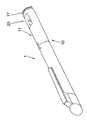
도 1은 그 정면 부분에 장착된 캡을 구비한, 본 발명에 따른 주사 디바이스의 제 1 실시예의 사시도.1 is a perspective view of a first embodiment of a scanning device according to the present invention with a cap mounted on its front portion;
도 2는 도 1로부터의 본 발명에 따른 주사 디바이스의 제 1 실시에의 개략 사시도.Figure 2 is a schematic perspective view of a first embodiment of a scanning device according to the invention from Figure 1;
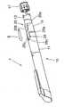
도 3은 본 발명에 따른 주사 디바이스의 제 2 실시예의 개략 사시도.3 is a schematic perspective view of a second embodiment of a scanning device according to the invention;
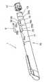
도 4는 본 발명에 따른 주사 디바이스의 제 3 실시예의 개략 사시도.4 is a schematic perspective view of a third embodiment of a scanning device according to the invention;
도 5는 본 발명에 따른 주사 디바이스의 제 4 실시예의 개략 사시도.5 is a schematic perspective view of a fourth embodiment of a scanning device according to the invention;
도 6은 본 발명에 따른 주사 디바이스의 제 5 실시예의 개략 사시도.Figure 6 is a schematic perspective view of a fifth embodiment of a scanning device according to the present invention;
도 7은 본 발명에 따른 주사 디바이스의 제 6 실시예의 개략 사시도.7 is a schematic perspective view of a sixth embodiment of a scanning device according to the present invention;
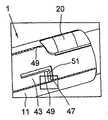
도 8은 본 발명에 따른 주사 디바이스의 오목부 및 상승된 표면 영역의 가장자리 선들의 프로파일의 실시예를 도시한 횡단면도로서, 주사 디바이스의 부품들, 특히 하우징과 디스플레이 슬리브의 원통 형상이 고려되지 않은 도면.Figure 8 is a cross-sectional view showing an embodiment of a profile of edge lines of a recessed portion and an elevated surface area of a scanning device according to the present invention, in which the parts of the scanning device, in particular the cylindrical shape of the housing and the display sleeve, .
도 9는 도 8에 도시된 도면에 따라서, 본 발명에 따른 주사 디바이스의 오목부 및 상승된 표면 영역의 가장자리 선들의 프로파일의 또 다른 실시예를 도시한 횡단면도.9 is a cross-sectional view of another embodiment of a profile of edge lines of a recessed portion and raised surface region of a scanning device according to the present invention, in accordance with the diagram shown in Fig.
도 10은 도 8에 따라서, 본 발명에 따른 주사 디바이스의 오목부와 상승된 표면 영역의 가장자리 선들의 프로파일의 또 다른 실시예의 횡단면도.10 is a cross-sectional view of another embodiment of a profile of edge lines of a recessed portion and an elevated surface region of a scanning device according to the present invention, in accordance with FIG.
도 11 내지 도 17은 삽입 슬리브를 축선 방향으로 하우징부에 록킹하기 위한 록킹 디바이스의 상이한 실시예들을 도시한 도면.Figures 11-17 illustrate different embodiments of a locking device for locking an insertion sleeve axially in a housing portion.
본 발명을 기술하도록, 상세한 설명 및 특허청구범위에서 사용된 용어들이 일부가 아래에 설명된다:In describing the present invention, some of the terms used in the description and the appended claims are set forth below:
용어 "기부" 및 "말단"은 본 발명에 따른 주사 디바이스의 부품들의 상대적인 위치를 정의하도록 사용된다. 여기에서, "기부"는 주사 디바이스가 의도된 바와 같이 사용될 때 환자를 향한 각각의 단부, 즉 주사 바늘을 향한 단부를 의미한다. 따라서, "말단"은 "기부" 단부로부터 멀리 향한 각각의 부품의 단부를 의미한다.The terms "base" and "end" are used to define the relative positions of components of a scanning device according to the present invention. Herein, "base" means the end toward each end, i.e., the needle, toward the patient when the scanning device is used as intended. Thus, "end" means the end of each component facing away from the "base" end.
주사 가능한 약물의 수용하기 위하여 이후에 기술되는 컨테이너는 특히 카트리지 또는 앰플일 수 있으며, 컨테이너가 예를 들어 원통형 또는 다른 단면 형상을 구비한 상이한 구성으로 디자인되는 것이 가능하다.The containers described hereinafter for accommodating injectable medicines may in particular be cartridges or ampoules, and it is possible for the container to be designed with different configurations, for example with cylindrical or other cross-sectional shapes.
본 발명은 의료용의 주사 가능한 조제품(용액, 현탁액, 에멀젼)을 수용하고 주사하기 위한 주사 디바이스에 기초하고, 주사 디바이스는, 수동 또는 자동, 기계적 또는 전기 기계적 투여에 적합하고 카트리지에서 축선 방향으로 안내되는 플런저에 의해 카트리지로부터 주사 바늘 내로 주사 가능한 조제품의 방출 원리에 따라서 작업한다. 이러한 주사 디바이스들은 폐기 가능한 디바이스로서 또는 재사용 가능한 디바이스로서 디자인된다.The present invention is based on a scanning device for receiving and scanning injectable preparations (solutions, suspensions, emulsions) for medical use, wherein the scanning device is adapted for manual or automatic, mechanical or electromechanical administration and is axially guided And operates according to the principle of ejection of the injectable preparation from the cartridge by the plunger into the injection needle. Such scanning devices are designed as disposable devices or as reusable devices.
본 발명에 따른 주사 디바이스는,A scanning device according to the present invention includes:
- 바람직하게 카트리지 홀더, 적절하다면 주사 바늘이 장착되며 주사 가능한 조제품을 수용하기 위한 카트리지를 구비하며, 주사 바늘이 카트리지 또는 카트리지 홀더 상에 장착되고, 주사 가능한 조제품이 주사 바늘을 통해 주사될 수 있는 카트리지 모듈,Preferably a cartridge holder, suitably equipped with a syringe needle and having a cartridge for receiving an injectable preparation, wherein the syringe needle is mounted on a cartridge or cartridge holder and the injectable preparation is injected through a needle module,
- 주사 가능한 조제품을 분배하도록 작동하는 분배 메커니즘, 구동 메커니즘, 또는 힘전달 메커니즘, 및A dispensing mechanism, a drive mechanism, or a force transfer mechanism that operates to dispense the injectable preparation, and
- 분배 메커니즘의 작동으로 분배되는 주사 가능한 조제품의 양을 한정하는 투여량을 조정하기 위한 투여량 조정 메커니즘을 포함한다.- a dose adjustment mechanism for adjusting the dose limiting the amount of the injectable preparation dispensed in operation of the dispensing mechanism.
하나의 예시적인 실시예에서, 약물을 분배하기 위한 본 발명에 따른 주사 디바이스(1)는, 주사 가능한 조제품을 수용하기 위한 컨테이너가 삽입되는 하우징을 포함한다. 하우징은 전방 또는 기부 하우징부와, 후방 또는 말단 하우징부로 구성된다. 대안적으로, 본 발명에 따른 주사 디바이스는 단일 부품형(one-part) 또는 단일 블록(monobloc) 하우징에 의해 또는 또 다른 하우징 구성에 의해 형성될 수 있다.In one exemplary embodiment, a
주사 가능한 조제품을 수용하기 위한 카트리지 또는 컨테이너는, 예를 들어, 기부 단부 및 말단 단부, 내부면과 외부면을 구비한 원통형 또는 다른 종방향 벽, 주사 가능한 조제품의 분배를 위한 전방 개구, 및 내부면을 따라서 움직이는 플런저가 그 안으로 안내될 수 있는 후방 개구를 포함한다. 그 시작 위치에서, 즉 용기가 완전히 채워지는 것에 의해, 플런저는 바람직하게 컨테이너의 말단 단부에 위치된다. 컨테이너는 그 말단 단부에 있는 개구와 함께 하우징 내로, 또는 적절하다 면, 하우징 내로 삽입을 위해 전방 하우징부 내로 직접 끼워질 수 있다.Cartridges or containers for receiving injectable preparations may contain, for example, a cylindrical or other longitudinal wall having a base end and a distal end, an inner surface and an outer surface, a forward opening for dispensing the injectable preparation, And a rear opening through which the moving plunger can be guided. In its starting position, that is, by fully filling the container, the plunger is preferably positioned at the distal end of the container. The container can be fitted directly into the housing with the opening at its distal end, or, if appropriate, directly into the front housing part for insertion into the housing.
주사 디바이스가 재사용 가능한 디바이스로서 디자인되면, 컨테이너는 컨테이너가 비워진 후에 적절하게 교체된다.If the scanning device is designed as a reusable device, the container is properly replaced after the container has been emptied.
그러므로, 주사 가능한 조제품을 수용하기 위한 컨테이너는 기부 단부와 말단 단부와 함께 컨테이너 수용 디바이스 또는 컨테이너 하우징 또는 컨테이너 홀더 내로 끼워질 수 있다. 그러나, 대안적으로, 컨테이너 홀더는 또한 외부 하우징으로서 작용할 수 있다. 이 경우에, 전방 하우징부는 컨테이너를 수용하기 위한 외부 하우징으로서 작용한다. 주사 바늘(도시되지 않음)은 컨테이너의 기부 단부 상에 장착되거나 또는 고정될 수 있으며, 주사 바늘은 적절하다면 외부 하우징, 또는 컨테이너 하우징의 기부 단부에 있는 개구를 통해 및/또는 하우징의 기부 단부에 있는 개구를 통해 컨테이너 내로 연장한다.Therefore, the container for receiving the injectable preparation can be fitted into the container receiving device or container housing or container holder with the base end and the terminal end. However, alternatively, the container holder may also act as an outer housing. In this case, the front housing part serves as an outer housing for receiving the container. A needle (not shown) can be mounted or fixed on the base end of the container, and the needle can be inserted through the opening in the outer housing, or the base end of the container housing, and / Extends through the opening into the container.
그러므로, 약물을 분배하기 위한 본 발명에 따른 주사 디바이스는 특히, 주사 가능한 조제품을 홀딩하는 컨테이너의 삽입을 위한 하우징, 및 하우징의 기부 단부 내로 삽입을 위하여, 주사 가능한 조제품의 전달을 위해 제공된 전방 개구를 구비하는 전방 기부 단부와, 후방 개구를 구비하고 시작 위치에서 분배 디바이스에 의해 카트리지의 축선 방향으로 변위 가능한 플런저가 끼워지는 후방 단부를 구비한 컨테이너를 포함한다.Therefore, a scanning device according to the invention for dispensing medicaments comprises in particular a housing for insertion of a container holding an injectable preparation and a front opening provided for delivery of the injectable preparation for insertion into the base end of the housing And a rear end having a rear opening and into which a plunger displaceable in the axial direction of the cartridge by the dispensing device at the start position is inserted.
투여량 조정 요소는,The dose-
- 하우징의 2 부분형 디자인(two-part design)에서, 분배 메커니즘의 적어도 일부가 수용되는 말단 하우징부인 하우징부(11),A
- 말단 하우징부 내로 적어도 부분적으로 끼워져서 그 안에서 회전 가능한 디스플레이 슬리브(13), 및A display sleeve (13) at least partly fitted into the end housing part and rotatable therein, and
- 말단 하우징 부분 내로 삽입될 수 있으며, 끼워진 상태에서, 하우징(10)에 의해 회전적으로 고정된 방식으로, 바람직하게 회전적으로 및 축선 방향으로 고정된 방식으로 수용되는 삽입 슬리브(15)에 의해 형성된다.Is insertable into the end housing portion and is formed by the
이러한 목적을 위하여, 삽입 슬리브(15)의 내경 및 디스플레이 슬리브(13)의 외경은 디스플레이 슬리브(13)가 삽입 슬리브(15) 내로 안내될 수 있도록 제공된다.For this purpose, the inner diameter of the
분배 메커니즘은 투여량 조정 메커니즘에 결합된다. 투여량 조정 메커니즘은 분배 메커니즘과 기계적으로 협동한다. 투여량 조정 메커니즘은 분배 메커니즘의 일체형 부품 부분일 수 있거나, 또는 분배 메커니즘으로부터 분리된 부품 부분일 수 있다.The dispensing mechanism is coupled to a dose adjustment mechanism. The dose adjustment mechanism cooperates mechanically with the dispensing mechanism. The dose adjustment mechanism may be an integral part of the dispensing mechanism, or it may be part of the part separated from the dispensing mechanism.
분배 메커니즘은 주사 가능한 조제품의 분배를 실행하고, 분배된 주사 가능한 조제품의 투여량은 투여량 조정 메커니즘에 의해 조정된다. 주사 가능한 조제품을 분배 또는 투여하도록, 분배 메커니즘은 예를 들어 주사 버튼의 형태로 하는 작동 요소(17)와, 플런저 로드에 의해 주사 버튼에 직접 또는 간접적으로 결합되는 플런저를 가질 수 있다.The dispensing mechanism performs dispensing of the injectable preparation and the dose of the dispensed injectable preparation is adjusted by a dose adjustment mechanism. To dispense or administer the injectable preparation, the dispensing mechanism may have a working
그러므로, 투여량 조정 메커니즘은, 특히 플런저로부터 디스플레이 슬리브(13)를 분리하는 것에 의해 말단 하우징에 대해 디스플레이 슬리브(13)의 축선 방향 위치를 조정하는 것에 의해 투여량을 조정하는 투여량 조정 기능을 가진다.The dose adjustment mechanism therefore has a dose adjustment function that adjusts the dose by adjusting the axial position of the
삽입 슬리브는 암나사를 가지며, 디스플레이 슬리브의 대응하는 숫나사 부분이 암나사 내로 수용될 수 있어서, 디스플레이 슬리브는 조정된 축선 방향 위치를 통해 분배될 주사 가능한 조제품의 투여량을 한정하기 위하여 삽입 슬리브에 대해 회전하는 것에 의하여 축선 방향으로 움직인다.The insertion sleeve has a female thread and a corresponding male portion of the display sleeve can be received within the female thread such that the display sleeve rotates relative to the insertion sleeve to define a dose of the injectable preparation to be dispensed through the adjusted axial position It moves in the axial direction by.
적절하다면, 삽입 슬리브는 주사 디바이스의 다른 부분에, 예를 들어 카트리지 모듈에 연결될 수 있으며, 특히 이러한 부분들과 결합되거나 또는 이러한 부분에 록킹될 수 있다.If appropriate, the insertion sleeve may be connected to other portions of the scanning device, for example, a cartridge module, and may be specifically coupled or locked to such portions.
주사 디바이스는, 투여량 조정 메커니즘에 의해 한정된 주사 가능한 조제품의 투여량이 플런저에 결합된 작동 디바이스의 작동에 의해 분배되는 투여량 투여 기능을 가진다. 이러한 목적을 위하여, 분배 메커니즘의 플런저 로드는 예를 들어 하우징 또는 말단 하우징부 내측에서 축선 방향으로 안내되어서, 플런저 로드의 축선 방향 움직임은 기부 방향으로의 플런저의 축선 방향 움직임을 유발하고, 이러한 것은 주사 가능한 조제품의 분배를 초래한다. 작동 디바이스는 주사 가능한 조제품의 분배를 실행하기 위하여 주사 디바이스를 사용하는 사람, 특히 환자 또는 의료 직원에 의해 또는 제어 수단에 의해 작동된다. 작동 및 투여 디바이스는 작동 요소의 작동 운동을 플런저 로드의 한정된 축선 방향 움직임으로 변환하고, 이러한 것은 차례로 환자에 의해 작동될 때 주사 바늘을 통하여 한정된 양의 주사 가능한 조제품을 분배하기 위해 플런저의 한정된 움직임을 실행한다.The scanning device has a dose administration function in which the dose of the injectable preparation defined by the dose adjustment mechanism is dispensed by operation of an actuating device coupled to the plunger. For this purpose, the plunger rod of the dispensing mechanism is guided in the axial direction, for example, inside the housing or end housing portion, so that the axial movement of the plunger rod causes an axial movement of the plunger in the direction of the base, Resulting in the distribution of possible preparations. The actuating device is operated by a person, in particular a patient or a medical staff, or by a control means, who uses the scanning device to effect the dispensing of the injectable preparation. The actuation and dispensing device converts the actuating movement of the actuating element into a limited axial movement of the plunger rod which, in turn, when actuated by the patient, causes a limited movement of the plunger to dispense a limited amount of injectable preparation through the needle .
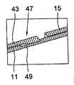
삽입 슬리브는 말단 하우징부 내로 안내될 수 있는 원통형 본체를 가진다. 회전적으로 고정된 방식으로 삽입 슬리브(15)를 수용하는 말단 하우징부에 대하여, 삽입 슬리브(15)는 적어도 일부 영역에서 투명한 계단 또는 상승된 표면 영역 또는 돌출부(20)를 그 외부면에서 더욱 압축한다.The insertion sleeve has a cylindrical body that can be guided into the distal housing portion. With respect to the end housing portion that receives the
본 발명의 또 다른 실시예에서, 상승된 표면 영역(20)은 하나 이상의 마킹(화살표, 선 등)이 제공되며, 마킹은, 조정되어 있고 디스플레이 슬리브 상에 나타나는 투여량을 삽입 슬리브를 통해 용이하게 읽게 할 수 있다. 이러한 마킹은 예를 들어 인쇄, 적층, 절단, 에칭 등과 같은 기계적 또는 화학적 수단에 의한 인쇄 또는 적층에 의해 적용될 수 있다.In another embodiment of the present invention, the raised
하우징은 오목부(25)를 가지며, 오목부는 그 말단 가장자리에서 개방되고, 삽입 슬리브(15)가 삽입 방향(E)으로 말단 하우징부(11) 내로 삽입될 때, 계단 또는 상승된 표면 영역(20)이 오목부의 개방 가장자리(26)의 방향으로부터 오목부 내로 안내되는 형상을 가진다.The housing has a
계단 또는 상승된 표면 영역(20)의 형상은, 표면 영역이 오목부 내로 원주 방향으로 사전 결정된 정밀도로 끼워지는 방식으로, 즉 말단 하우징부의 축선 방향으로 연장하는 오목부(25)의 가장자리(25a, 25b)들의 상호 대면하는 내부면들이 삽입 슬리브의 원주 방향으로 계단 또는 상승된 표면 영역(20)의 폭(B)보다 크거나 또는 작은 일정 범위의 거리만큼 이격되는 방식으로 제공된다. 대안적으로, 대응하는 오목부 가장자리(25a, 25b)들과 계단 또는 상승된 표면 영역(20)은 헐거운 끼워맞춤, 중간 끼워맞춤 또는 간섭 끼워맞춤을 형성할 수 있다.The shape of the step or raised
끼워맞춤 및 개방 가장자리(26)를 구비한 오목부의 준비를 제공하는 오목부와 상승된 표면 영역(20)의 치수화는 특히 이러한 것이 보다 용이하게 및/또는 큰 정밀도로 행해질 수 있기 때문에 주사 디바이스의 조립의 견지에서 유익하며, 이러한 것은 예를 들어 조립 작업의 자동화를 유도할 수 있다.The dimensioning of the recesses and the raised
오목부(25)는, 상승된 표면 영역(20) 또는 오목부(25)에 있는 연결 가장자리(25c)의 축선 방향 단부 위치에 대한 접합점(abutment)을 형성하는 접경 가장자리 또는 기부 가장자리(26)를 가진다.The
삽입 슬리브의 한 실시예에서, 그 내부면은 디스플레이 슬리브(13)의 회전 위치의 함수로서 디스플레이 슬리브를 축선 방향으로 조정하기 위하여 디스플레이 슬리브의 선택적으로 존재하는 수나사와 협동하는 안내 디바이스를 구비한다. 중간 끼워맞춤 또는 간섭 끼워맞춤에 의해, 하우징부(11)에 대한 디스플레이 슬리브(13)의 축선 방향 위치는 디스플레이 슬리브(13)의 각각의 회전 위치의 함수로서 더욱 정밀하게 제공될 수 있다. 이러한 방식으로, 차례로 조정된 투여량이 주사 디바이스에 의해 분배되는 정밀도를 증가시키는 것이 가능하다.In one embodiment of the insertion sleeve, its inner surface is provided with a guiding device cooperating with the optionally present male thread of the display sleeve to axially adjust the display sleeve as a function of the rotational position of the
또한, 상승된 표면 영역(20)의 두께를 증가시키는 것에 의해, 예를 들어, 크게 보이는 유리로서 이를 구성하는 것에 의해, 투여량 조정의 가시성이 증가될 수 있다. 이러한 방식으로, 조정 투여량이 사용자에 의해 분배되는 정밀도를 개선하는 것이 가능하다.Also, by increasing the thickness of the raised
그 축선 방향으로 연장하는 측부 가장자리(20a, 20b) 및 기부 가장자리 또는 접경 가장자리(20c)를 구비한 계단 또는 상승된 표면 영역(200)의 형상과, 오목부(25)의 형상을 다를 수 있다.The shape of the recessed
도 1 및 도 2에 도시된 바와 같이, 상승된 표면 영역의 접경 가장자리(20c), 및 오목부의 접경 가장자리(25c)들은 직선으로 및 원주 방향으로 연장할 수 있다.As shown in Figs. 1 and 2, the abutting
도 3에 도시된 바와 같이, 상승된 표면 영역의 접경 가장자리(20c), 및 오목부의 접경 가장자리(25c)들은, 서로 일정 각도로 연장하고 특히 한 지점으로 가늘어지는 2개의 선 영역들에 의해 형성될 수 있다.As shown in Fig. 3, the
도 4에 도시된 바와 같이, 상승된 표면 영역(20)의 종방향 가장자리(20a, 20b) 및 접경 가장자리(20c), 및 오목부의 종방향 가장자리(25a, 25b) 및 접경 가장자리(25c)들은 곡선으로서 형성될 수 있어서, 상승된 표면 영역(20)과 오목부의 윤곽들은 부분적으로 타원 형상이다.4, the
도 5에 도시된 바와 같이, 상승된 표면 영역(20)의 윤곽의 각각의 대안적인 구성에서, 상승된 표면 영역의 상부는 특히 추가의 돌출부(30)의 투명 부분에서 크게 보이는 유리 효과를 제공하기 위하여 추가의 돌출부(30)가 형성되는 것이 가능하다.5, in each alternative configuration of the contour of the raised
도 6에 도시된 바와 같이, 상승된 표면 영역(20)의 종방향 가장자리(20a, 20b), 및 오목부(25)의 종방향 가장자리(25a, 25b)들은 직선으로, 특히 서로에 대해 평행하게 연장할 수 있으며, 상승된 표면 영역(20)의 접경 가장자리(20c), 및 오목부(25)의 접경 가장자리(25c)들은 곡선으로 형성될 수 있다.The
도 7에 도시된 바와 같이, 특히 도 6에 따른 상승된 표면 영역(20)의 윤곽선들의 구성에서, 그 상부는 특히 추가의 돌출부(30)의 투명 부분에서 크게 보이는 유리 효과를 제공하기 위하여 추가의 돌출부(30)가 형성되는 것이 가능하다.As shown in Fig. 7, particularly in the configuration of the contours of the raised
본 발명에 따라서, 록킹 디바이스는 축선 방향으로 하우징부(11)에 삽입 슬 리브(15)를 록킹하기 위해 제공될 수 있다. 이러한 것은 상이한 방식들로 행해질 수있다. 예를 들어, 외부면, 즉 하우징부(11)로 향하여 안내되는 삽입 슬리브(15)의 면은 록킹 돌출부가 제공될 수 있으며, 하우징부(11)의 내부면 상의 대응하는 지점은 특히 록킹 구멍(locking aperture)의 형태를 하는 록킹 그루브 또는 록킹 함몰부 또는 록킹 오목부가 제공될 수 있으며, 이것들은 삽입 슬리브(15)가 그 단부 위치로 하우징부(11) 내로 가압될 때 서로 록킹된다.According to the present invention, the locking device can be provided for locking the insertion slit 15 in the
오목부와 상승된 표면 영역의 가장자리들은 상이한 방식들로 구성될 수 있다. 예를 들어, 오목부(25)와 상승된 표면 영역(20)의 종방향 가장자리 및/또는 접경 가장자리들은 형상 끼워맞춤으로 결합되도록 구성될 수 있다. 오목부(25)와 상승된 표면 영역(20)의 각각의 가장자리면(edge face)들은 도브테일(dovetail) 가이드 또는 다른 형태의 가이드를 형성할 수 있다. 도 8 내지 도 10은, 비록 가장자리면들이 대안적으로 또는 부가적으로 접경 가장자리들의 가장자리면들에 형성될 수 있을지라도, 상승된 표면 영역과 오목부의 종방향 가장자리들에 대한 가장자리면들의 구성을 도시한다.The edges of the concave and raised surface areas can be constructed in different ways. For example, the longitudinal and / or transverse edges of the
도 8은 도브테일 가이드를 도시하고, 도브테일 가이드에서, 상승된 표면 영역의 종방향 가장자리(20a, 20b)의 가장자리면은 오목부(25)의 가장자리면에 있는 대응하여 각이진 오목부에서 결합하는 각이진 가이드부를 가진다. 도 9는, 역으로 오목부(25)의 가장자리면이 상승된 표면 영역(20)의 종방향 가장자리(20a, 20b)에 있는 대응하여 각이진 오목부에서 결합하는 각이진 가이드부를 가지는, 도 8에 따른 도브테일 가이드의 변형을 도시한다. 도 10에 따른 가이드의 실시예에서, 오목 부의 가장자리면에 있는 가이드는 그루브로서 디자인되지만, 상승된 표면 영역의 가장자리면은 그루브에서 결합하는 대응하는 접합편(mating piece)을 가진다. 유사하게, 그루브는 대안적으로 오목부의 가장자리면에 형성될 수 있으며, 대응하는 접합편은 상승된 표면 영역의 가장자리면에 형성될 수 있다.Figure 8 shows a dovetail guide in which the edge surfaces of the
말단 하우징부는, 오목부 가장자리를 따라서, 오염물 및/또는 습기로부터 말단 하우징부의 내부를 더욱 효과적으로 밀봉하기 위하여 밀봉부가 제공될 수 있다.The end housing portion may be provided with a seal along the recessed edge to more effectively seal the interior of the end housing portion from contaminants and / or moisture.
밀봉부는 오목부(25)의 가장자리들을 따라서, 즉 종방향 가장자리(25a, 25b) 및 접경 가장자리를 따라서 배열될 수 있다. 대안적으로 또는 부가적으로, 밀봉부는 바람직하게 삽입 슬리브(15)의 말단 단부의 가장자리를 따라서 삽입 슬리브(15)의 말단 단부와 내부면에서 배열될 수 있다. 이러한 밀봉부는 바람직하게 삽입 슬리브(15)의 외부 원주 주위에서 연장하는 밀봉부로서 디자인된다. 밀봉부는 환형 형상, 특히 브러쉬 형상을 가질 수 있다. 상기된 대안에 있어서, 밀봉부는 특히 삽입 슬리브(15)의 말단 가장자리의 개구 주위에서 연장할 수 있다.The seal can be arranged along the edges of the
삽입 슬리브(15) 상의 상기된 밀봉부는 삽입 슬리브(15)의 내부면과 디스플레이 슬리브(13)의 외부면 사이에서 작용하고, 특히 디스플레이 슬리브(13)와 삽입 슬리브(15) 사이에서 미립자 또는 액체의 진입을 감소 또는 방지하도록, 그러므로 하우징부(11)의 내부의 오염을 감소 또는 방지하도록 작용한다.The aforementioned seal on the
하우징부(11)의 내부의 오염을 방지하도록, 밀봉부는 대안적으로 또는 부가적으로 바람직하게 삽입 슬리브(15)의 말단 단부의 가장자리를 따라서 삽입 슬리브(15)의 말단 단부와 외부면에 배열될 수 있다. 부가적으로 또는 대안적으로, 이 러한 밀봉부는 삽입 슬리브(15)의 외부면의 원주 주위에서 상승된 표면 영역(20)의 기부면에서 연장할 수 있다.In order to prevent contamination of the interior of the
주사 디바이스(1) 상에 다수의 계단 또는 상승된 표면 영역(20), 및 다수의 오목부(25)들을 제공하는 것이 또한 가능하다.It is also possible to provide a plurality of steps or
도 11 내지 도 17은 축선 방향으로 하우징부(11)에 삽입 슬리브(15)를 록킹하기 위한 록킹 디바이스(40)의 상이한 실시예들을 도시한다.Figs. 11 to 17 show different embodiments of the
록킹 디바이스(40)는 수용 디바이스(49)와, 또한 탭(tab) 또는 텅(43)을 가질 수 있으며, 탭 또는 텅은 하우징부(11)의 함몰부 또는 오목부(41)에서 연장하고, 그 기부 단부(45)에서 삽입 슬리브(15)에 연결되고, 그 말단 단부에서 자유 단부(47)를 형성한다. 자유 단부(47)는 삽입 슬리브(15)가 그 단부 위치로 하우징부(11) 내로 가압될 때 수용 디바이스(49)에서 결합하는 록킹 돌출부의 형태를 하는 외향 돌출 가장자리 영역(51, 51a, 51b)들을 형성한다. 록킹 돌출부(51, 51a, 51b)들은 텅(43)의 외향 연장 및 각이진 연장부에 의해 및/또는 자유 단부(47)에 형성된 록킹 캠(51, 51a, 51b)들에 의해 형성될 수 있다.The locking
도 11 내지 도 15에 도시된 바와 같이, 록킹 디바이스(40)와 협동하는 수용 디바이스(49)는 하우징부(11)의 내부면 상의 함몰부로서 디자인될 수 있다. 대안적으로, 수용 디바이스(49)는 구멍의 형태로 하는 오목부로서 디자인될 수 있다(도 16 및 도 17).11 to 15, the receiving
수용 디바이스(49)는, 록킹 돌출부(51, 51a, 51b)의 폭에 일치하고 및/또는 삽입 슬리브와 끼워맞춤을 형성하는 폭만큼 원주 방향으로 연장할 수 있다. 이러한 끼워맞춤은 돌출부와 함께 디자인된 이전의 끼워맞춤 대신에 제공될 수 있다. 수용 디바이스(49)는 록킹 돌출부(51, 51a, 51b)의 폭을 지나서 원주 방향으로 연장할 수 있으며, 특히 하우징부(11)의 내부 원주면 상의 함몰부로서 디자인될 수 있다(도 11 및 도 12).The receiving
자유 단부(47)는 단독으로 또는 다중으로 분할된 자유 단부로서 디자인될 수 있어서, 하나 이상의 록킹 돌출부(51, 51a, 51b), 특히 하나 이상의 록킹 캠들이 제공될 수 있다. 도 16 및 도 17은 단독으로 분할된 자유 단부를 구비한, 그러므로 록킹 캠들의 형태를 하는 2개의 록킹 돌출부(51a, 51b)들을 구비한 록킹 디바이스의 실시예를 도시한다. 따라서, 수용 디바이스(49)는 2개의 함몰부 또는 오목부(49a, 49b)들을 가진다.The
다수의 텅(43)들은 원주 방향으로, 일치하여 함몰부 또는 오목부들과 같은 다수의 수용 디바이스에 제공될 수 있다.The plurality of
다수 쌍의 텅(43)과 수용 디바이스를 구비한 실시예에서, 이것들은 동일한 축선 방향 위치에 배열될 수 있거나, 또는 축선 방향으로 상호 편심될 수 있다.In embodiments with multiple pairs of
Claims (42)
Translated fromKoreanApplications Claiming Priority (3)
| Application Number | Priority Date | Filing Date | Title |
|---|---|---|---|
| DE102007018696ADE102007018696A1 (en) | 2007-04-18 | 2007-04-18 | Injection device for dispensing a medicament |
| DE102007018696.9 | 2007-04-18 | ||
| PCT/EP2008/002787WO2008128645A1 (en) | 2007-04-18 | 2008-04-09 | Injection device for delivering a medication |
Publications (2)
| Publication Number | Publication Date |
|---|---|
| KR20100015555A KR20100015555A (en) | 2010-02-12 |
| KR101523237B1true KR101523237B1 (en) | 2015-05-28 |
Family
ID=39672755
Family Applications (1)
| Application Number | Title | Priority Date | Filing Date |
|---|---|---|---|
| KR1020097021401AActiveKR101523237B1 (en) | 2007-04-18 | 2008-04-09 | Injection device for delivering a medication |
Country Status (18)
| Country | Link |
|---|---|
| US (1) | US10449299B2 (en) |
| EP (1) | EP2148710B1 (en) |
| JP (1) | JP5396381B2 (en) |
| KR (1) | KR101523237B1 (en) |
| CN (1) | CN101663060B (en) |
| AR (1) | AR066074A1 (en) |
| AU (1) | AU2008241089B2 (en) |
| BR (1) | BRPI0810032B8 (en) |
| CA (1) | CA2684351A1 (en) |
| DE (1) | DE102007018696A1 (en) |
| DK (1) | DK2148710T3 (en) |
| ES (1) | ES2758526T3 (en) |
| HU (1) | HUE046604T2 (en) |
| IL (1) | IL201500A (en) |
| MX (1) | MX2009010804A (en) |
| PL (1) | PL2148710T3 (en) |
| TW (1) | TWI487546B (en) |
| WO (1) | WO2008128645A1 (en) |
Families Citing this family (28)
| Publication number | Priority date | Publication date | Assignee | Title |
|---|---|---|---|---|
| US20070202186A1 (en) | 2006-02-22 | 2007-08-30 | Iscience Interventional Corporation | Apparatus and formulations for suprachoroidal drug delivery |
| US8197435B2 (en) | 2006-05-02 | 2012-06-12 | Emory University | Methods and devices for drug delivery to ocular tissue using microneedle |
| GB0918145D0 (en) | 2009-10-16 | 2009-12-02 | Owen Mumford Ltd | Injector apparatus |
| JP5996544B2 (en) | 2010-10-15 | 2016-09-21 | クリアサイド・バイオメディカル・インコーポレーテッドClearside Biomedical Incorporated | Eye access device |
| US9452265B2 (en) | 2011-03-18 | 2016-09-27 | Becton, Dickinson And Company | End of injection indicator for injection pen |
| US9993598B2 (en)* | 2011-10-06 | 2018-06-12 | Sanofi-Aventis Deutschland Gmbh | Display arrangement for a drug delivery device |
| EP2830685B1 (en)* | 2012-03-30 | 2017-05-31 | Tecpharma Licensing AG | Injection device with a dose display element displaceable relative to a housing. |
| MX360468B (en)* | 2012-04-05 | 2018-11-05 | Sanofi Aventis Deutschland | Pen -type injector with window element. |
| RU2724011C1 (en) | 2012-04-13 | 2020-06-18 | Бектон, Дикинсон Энд Компани | Automated device for injections |
| KR20210133321A (en) | 2012-11-08 | 2021-11-05 | 클리어사이드 바이오메디컬, 인코포레이드 | Methods and devices for the treatment of ocular disease in human subjects |
| CA2911290C (en) | 2013-05-03 | 2021-07-27 | Clearside Biomedical, Inc. | Apparatus and methods for ocular injection |
| EP3003454B1 (en) | 2013-06-03 | 2020-01-08 | Clearside Biomedical, Inc. | Apparatus for drug delivery using multiple reservoirs |
| US10668218B2 (en)* | 2013-08-29 | 2020-06-02 | Sanofi-Aventis Deutschland Gmbh | Housing and cap for an injection device made of an outer metal part and an inner plastic part |
| CA155281S (en)* | 2013-09-04 | 2015-02-10 | Sanofi Aventis Deutschland | Injection device with cap |
| CA155482S (en)* | 2013-09-20 | 2014-10-27 | Sanofi Aventis Deutschland | Injection device with cap |
| JP6543250B2 (en) | 2013-12-05 | 2019-07-10 | ノボ・ノルデイスク・エー/エス | Housing for medical injection device |
| RU2710491C2 (en) | 2014-06-20 | 2019-12-26 | Клиасайд Байомедикал, Инк. | Device for drug injection into ocular tissue and method for drug injection into ocular tissue |
| USD750223S1 (en) | 2014-10-14 | 2016-02-23 | Clearside Biomedical, Inc. | Medical injector for ocular injection |
| US10799644B2 (en) | 2015-06-01 | 2020-10-13 | Novo Nordisk A/S | Method for moulding a polymeric housing for a medical injection device |
| EP3413851B1 (en) | 2016-02-10 | 2023-09-27 | Clearside Biomedical, Inc. | Packaging |
| US9694145B1 (en)* | 2016-03-29 | 2017-07-04 | Joseph Onorato | Auto-injector systems and method for delivering cyst medication on demand |
| WO2017192565A1 (en) | 2016-05-02 | 2017-11-09 | Clearside Biomedical, Inc. | Systems and methods for ocular drug delivery |
| US10973681B2 (en) | 2016-08-12 | 2021-04-13 | Clearside Biomedical, Inc. | Devices and methods for adjusting the insertion depth of a needle for medicament delivery |
| US12090294B2 (en) | 2017-05-02 | 2024-09-17 | Georgia Tech Research Corporation | Targeted drug delivery methods using a microneedle |
| USD893715S1 (en) | 2018-11-06 | 2020-08-18 | Joseph Onorato | Measurement guide for a cyst, lesion or skin disorder |
| EP4596001A1 (en)* | 2024-02-02 | 2025-08-06 | Ypsomed AG | Magnifying lens for a drug delivery device |
| WO2025162755A1 (en)* | 2024-02-02 | 2025-08-07 | Ypsomed Ag | Magnifying lens for a drug delivery device |
| EP4596002A1 (en)* | 2024-02-02 | 2025-08-06 | Ypsomed AG | Magnifying lens for a drug delivery device |
Citations (1)
| Publication number | Priority date | Publication date | Assignee | Title |
|---|---|---|---|---|
| CA2359375A1 (en)* | 1999-01-14 | 2000-07-20 | B D Medico S.A.R.L. | Injection device |
Family Cites Families (67)
| Publication number | Priority date | Publication date | Assignee | Title |
|---|---|---|---|---|
| US533575A (en) | 1895-02-05 | wilkens | ||
| US3973554A (en)* | 1975-04-24 | 1976-08-10 | The United States Of America As Represented By The Secretary Of The Department Of Health, Education And Welfare | Radiation safety shield for a syringe |
| DE3638984C3 (en)* | 1986-11-14 | 1993-11-18 | Haselmeier Wilhelm Fa | Injection device |
| DE3715340C2 (en) | 1987-05-08 | 1995-10-19 | Haselmeier Wilhelm Fa | Injection device |
| DE3715258C2 (en) | 1987-05-08 | 1996-10-31 | Haselmeier Wilhelm Fa | Injection device |
| GB8713810D0 (en) | 1987-06-12 | 1987-07-15 | Hypoguard Uk Ltd | Measured dose dispensing device |
| US5226895A (en) | 1989-06-05 | 1993-07-13 | Eli Lilly And Company | Multiple dose injection pen |
| GB9007113D0 (en) | 1990-03-29 | 1990-05-30 | Sams Bernard | Dispensing device |
| US5226896A (en) | 1990-04-04 | 1993-07-13 | Eli Lilly And Company | Dose indicating injection pen |
| AU641206B2 (en) | 1991-01-22 | 1993-09-16 | Eli Lilly And Company | Multiple dose injection pen |
| DK0525525T3 (en) | 1991-07-24 | 1995-10-02 | Medico Dev Investment Co | Injector |
| DK175491D0 (en) | 1991-10-18 | 1991-10-18 | Novo Nordisk As | APPARATUS |
| US5279585A (en) | 1992-02-04 | 1994-01-18 | Becton, Dickinson And Company | Medication delivery pen having improved dose delivery features |
| US5271527A (en) | 1992-04-02 | 1993-12-21 | Habley Medical Technology Corporation | Reusable pharmaceutical dispenser with full stroke indicator |
| US5300041A (en) | 1992-06-01 | 1994-04-05 | Habley Medical Technology Corporation | Dose setting and repeating syringe |
| US5391157A (en) | 1992-10-20 | 1995-02-21 | Eli Lilly And Company | End of dose indicator |
| US5378233A (en) | 1992-11-18 | 1995-01-03 | Habley Medical Technology Corporation | Selected dose pharmaceutical dispenser |
| US5320609A (en) | 1992-12-07 | 1994-06-14 | Habley Medical Technology Corporation | Automatic pharmaceutical dispensing syringe |
| FR2701211B1 (en) | 1993-02-08 | 1995-05-24 | Aguettant Lab | DOSING INSTRUMENT, ESPECIALLY INJECTION |
| US5383865A (en) | 1993-03-15 | 1995-01-24 | Eli Lilly And Company | Medication dispensing device |
| ZA941881B (en) | 1993-04-02 | 1995-09-18 | Lilly Co Eli | Manifold medication injection apparatus and method |
| US5725508A (en)* | 1994-06-22 | 1998-03-10 | Becton Dickinson And Company | Quick connect medication delivery pen |
| US5582598A (en) | 1994-09-19 | 1996-12-10 | Becton Dickinson And Company | Medication delivery pen with variable increment dose scale |
| US5569214A (en)* | 1994-09-20 | 1996-10-29 | Becton Dickinson And Company | Dose setting knob adapter for medication delivery pen |
| JP3568959B2 (en) | 1995-03-07 | 2004-09-22 | イーライ・リリー・アンド・カンパニー | Reusable dosing device |
| JP3802064B2 (en)* | 1995-06-02 | 2006-07-26 | ノボ ノルディスク アクティーゼルスカブ | Automatic retracting piston rod |
| AU1860697A (en) | 1995-09-08 | 1997-07-28 | Visionary Medical Products Corporation | Pen-type injector drive mechanism |
| US5688251A (en) | 1995-09-19 | 1997-11-18 | Becton Dickinson And Company | Cartridge loading and priming mechanism for a pen injector |
| US5674204A (en) | 1995-09-19 | 1997-10-07 | Becton Dickinson And Company | Medication delivery pen cap actuated dose delivery clutch |
| US5851079A (en) | 1996-10-25 | 1998-12-22 | The Procter & Gamble Company | Simplified undirectional twist-up dispensing device with incremental dosing |
| DE19730999C1 (en)* | 1997-07-18 | 1998-12-10 | Disetronic Licensing Ag | Injection pen dosing selected volume of fluid, especially insulin |
| US5921966A (en) | 1997-08-11 | 1999-07-13 | Becton Dickinson And Company | Medication delivery pen having an improved clutch assembly |
| CZ297361B6 (en)* | 1998-01-30 | 2006-11-15 | Novo Nordisk A/S | Injection syringe |
| US5961495A (en) | 1998-02-20 | 1999-10-05 | Becton, Dickinson And Company | Medication delivery pen having a priming mechanism |
| US6221053B1 (en) | 1998-02-20 | 2001-04-24 | Becton, Dickinson And Company | Multi-featured medication delivery pen |
| US6248095B1 (en) | 1998-02-23 | 2001-06-19 | Becton, Dickinson And Company | Low-cost medication delivery pen |
| GB9812472D0 (en)* | 1998-06-11 | 1998-08-05 | Owen Mumford Ltd | A dose setting device for medical injectors |
| CA2345439C (en)* | 1998-10-29 | 2005-08-09 | Minimed, Inc. | Compact pump drive system |
| US20050197626A1 (en)* | 1998-10-29 | 2005-09-08 | Medtronic Minimed Inc. | Fluid reservoir for use with an external infusion device |
| DE19900827C1 (en) | 1999-01-12 | 2000-08-17 | Disetronic Licensing Ag | Device for the dosed administration of an injectable product |
| DE19900792C1 (en) | 1999-01-12 | 2000-06-15 | Disetronic Licensing Ag | Injection unit forming part of e.g. pen-type self-injection syringe has continuous dosing stop in spiral form with constant pitch ensuring close fine control and accuracy in use |
| SE9901366D0 (en) | 1999-04-16 | 1999-04-16 | Pharmacia & Upjohn Ab | Injector device and method for its operation |
| AU6892100A (en) | 1999-08-05 | 2001-03-05 | Becton Dickinson & Company | Medication delivery pen |
| GB0007071D0 (en) | 2000-03-24 | 2000-05-17 | Sams Bernard | One-way clutch mechanisms and injector devices |
| US6663602B2 (en) | 2000-06-16 | 2003-12-16 | Novo Nordisk A/S | Injection device |
| FR2813533B1 (en)* | 2000-09-01 | 2003-03-07 | Lemer Pax | PROTECTIVE DEVICE FOR A SYRINGE, PARTICULARLY FOR A SYRINGE FOR INJECTING RADIOACTIVE PRODUCT (S) |
| CN1268405C (en) | 2000-10-09 | 2006-08-09 | 伊莱利利公司 | Pen device for administration of parathyroid hormone |
| US6899699B2 (en) | 2001-01-05 | 2005-05-31 | Novo Nordisk A/S | Automatic injection device with reset feature |
| DE10106368B4 (en)* | 2001-02-12 | 2006-02-02 | Tecpharma Licensing Ag | An adjustment barrier for a device for administering an adjustable dose of an injectable product |
| WO2002064092A2 (en)* | 2001-02-15 | 2002-08-22 | Kosan Biosciences, Inc. | Method for evaluating therapeutic efficacy |
| ES2365807T3 (en) | 2001-05-16 | 2011-10-11 | ELI LILLY & COMPANY | MEDICATION INJECTOR DEVICE WITH MOTOR ASSEMBLY THAT FACILITATES REARME. |
| JP4350525B2 (en) | 2002-03-18 | 2009-10-21 | イーライ リリー アンド カンパニー | Drug dispensing device with gear set giving mechanical advantages |
| US7454458B2 (en)* | 2002-06-24 | 2008-11-18 | Ntt Docomo, Inc. | Method and system for application load balancing |
| EP1545663B1 (en) | 2002-10-01 | 2006-08-30 | Becton Dickinson and Company | Medication delivery pen |
| GB0304822D0 (en) | 2003-03-03 | 2003-04-09 | Dca Internat Ltd | Improvements in and relating to a pen-type injector |
| GB0304823D0 (en) | 2003-03-03 | 2003-04-09 | Dca Internat Ltd | Improvements in and relating to a pen-type injector |
| US6932794B2 (en) | 2003-04-03 | 2005-08-23 | Becton, Dickinson And Company | Medication delivery pen |
| EP1541185A1 (en) | 2003-12-08 | 2005-06-15 | Novo Nordisk A/S | Automatic syringe with priming mechanism |
| DE102004004310A1 (en)* | 2004-01-28 | 2005-08-18 | Tecpharma Licensing Ag | Injection device with lockable dosing member |
| MX2007003682A (en)* | 2004-10-04 | 2007-08-07 | Sanofi Aventis Deutschland | Drive mechanism for a drug delivery device. |
| EP1642607A1 (en)* | 2004-10-04 | 2006-04-05 | Sanofi-Aventis Deutschland GmbH | Dose display mechanism for a drug delivery device |
| DE102004063644A1 (en) | 2004-12-31 | 2006-07-20 | Tecpharma Licensing Ag | Device for the dosed administration of a fluid product with torsion spring drive |
| US8257318B2 (en) | 2005-02-11 | 2012-09-04 | Novo Nordisk A/S | Injection device having a rotatable scale drum |
| US8062252B2 (en)* | 2005-02-18 | 2011-11-22 | Becton, Dickinson And Company | Safety shield system for a syringe |
| US20080269688A1 (en)* | 2005-12-08 | 2008-10-30 | Jose Colucci | Dose Indicating Assembly of a Pharmaceutical Injection Device |
| US8187233B2 (en) | 2008-05-02 | 2012-05-29 | Sanofi-Aventis Deutschland Gmbh | Medication delivery device |
| US8647309B2 (en) | 2008-05-02 | 2014-02-11 | Sanofi-Aventis Deutschland Gmbh | Medication delivery device |
- 2007
- 2007-04-18DEDE102007018696Apatent/DE102007018696A1/ennot_activeWithdrawn
- 2008
- 2008-04-09HUHUE08748875Apatent/HUE046604T2/enunknown
- 2008-04-09ESES08748875Tpatent/ES2758526T3/enactiveActive
- 2008-04-09WOPCT/EP2008/002787patent/WO2008128645A1/enactiveApplication Filing
- 2008-04-09DKDK08748875.5Tpatent/DK2148710T3/enactive
- 2008-04-09MXMX2009010804Apatent/MX2009010804A/enactiveIP Right Grant
- 2008-04-09AUAU2008241089Apatent/AU2008241089B2/enactiveActive
- 2008-04-09JPJP2010503381Apatent/JP5396381B2/enactiveActive
- 2008-04-09CACA002684351Apatent/CA2684351A1/ennot_activeAbandoned
- 2008-04-09EPEP08748875.5Apatent/EP2148710B1/enactiveActive
- 2008-04-09BRBRPI0810032Apatent/BRPI0810032B8/enactiveIP Right Grant
- 2008-04-09KRKR1020097021401Apatent/KR101523237B1/enactiveActive
- 2008-04-09CNCN200880012589XApatent/CN101663060B/enactiveActive
- 2008-04-09PLPL08748875Tpatent/PL2148710T3/enunknown
- 2008-04-16ARARP080101558Apatent/AR066074A1/enactiveIP Right Grant
- 2008-04-16TWTW097113720Apatent/TWI487546B/enactive
- 2009
- 2009-10-09USUS12/576,374patent/US10449299B2/enactiveActive
- 2009-10-13ILIL201500Apatent/IL201500A/enactiveIP Right Grant
Patent Citations (1)
| Publication number | Priority date | Publication date | Assignee | Title |
|---|---|---|---|---|
| CA2359375A1 (en)* | 1999-01-14 | 2000-07-20 | B D Medico S.A.R.L. | Injection device |
Also Published As
| Publication number | Publication date |
|---|---|
| BRPI0810032B8 (en) | 2021-06-22 |
| CA2684351A1 (en) | 2008-10-30 |
| TW200909015A (en) | 2009-03-01 |
| AR066074A1 (en) | 2009-07-22 |
| MX2009010804A (en) | 2009-10-29 |
| EP2148710A1 (en) | 2010-02-03 |
| JP2010524526A (en) | 2010-07-22 |
| ES2758526T3 (en) | 2020-05-05 |
| US20100152667A1 (en) | 2010-06-17 |
| WO2008128645A1 (en) | 2008-10-30 |
| HK1141745A1 (en) | 2010-11-19 |
| BRPI0810032A2 (en) | 2014-10-14 |
| US10449299B2 (en) | 2019-10-22 |
| AU2008241089A1 (en) | 2008-10-30 |
| EP2148710B1 (en) | 2019-10-02 |
| CN101663060B (en) | 2013-11-06 |
| HUE046604T2 (en) | 2020-03-30 |
| JP5396381B2 (en) | 2014-01-22 |
| CN101663060A (en) | 2010-03-03 |
| IL201500A (en) | 2012-12-31 |
| DK2148710T3 (en) | 2019-12-16 |
| IL201500A0 (en) | 2010-05-31 |
| KR20100015555A (en) | 2010-02-12 |
| DE102007018696A1 (en) | 2008-10-23 |
| TWI487546B (en) | 2015-06-11 |
| PL2148710T3 (en) | 2020-03-31 |
| AU2008241089B2 (en) | 2013-02-28 |
| BRPI0810032B1 (en) | 2019-02-12 |
Similar Documents
| Publication | Publication Date | Title |
|---|---|---|
| KR101523237B1 (en) | Injection device for delivering a medication | |
| US8585656B2 (en) | Dose setting mechanism for priming a drug delivery device | |
| US9457150B2 (en) | Biasing mechanism for a drug delivery device | |
| ES2710438T3 (en) | Method of mounting devices for the administration of medicines | |
| US7766874B2 (en) | Catheter head comprising a mobile connector | |
| CN101500630B (en) | Coupling for an injection device | |
| EP0713403B1 (en) | Dosing syringe | |
| ES2982391T3 (en) | Medical administration device | |
| HUP0102525A2 (en) | A medical delivery device and a cartridge assembly for use in the same | |
| IL159661A (en) | Reservoir module with a piston rod | |
| AU2007207309A1 (en) | Injection device with secured dosing button | |
| US20040243066A1 (en) | Single use safety syringe | |
| AU2007207310A1 (en) | Pusher with a coupling element | |
| ZA200500356B (en) | Administration device comprising a plunger rod with a return lock | |
| WO2022090463A1 (en) | Administration device for in particular intravitreal administration of a fluid | |
| JP2021100588A (en) | Housing for mounting container on injection pen, assembly for forming injection agent storage tank for injection pen and injection pen including assembly | |
| CN117940180A (en) | Medical delivery devices | |
| HK1141745B (en) | Injection device for dispensing a medicament | |
| US20220323694A1 (en) | Keyed connectors | |
| CN117425510A (en) | Drug delivery device | |
| EA047899B1 (en) | DEVICE FOR DELIVERY OF A PRECISION DOSE (VARIANTS) AND METHOD FOR DELIVERY OF A PRECISION DOSE | |
| CZ20004892A3 (en) | Drug delivery device and cartridge assembly for this device |
Legal Events
| Date | Code | Title | Description |
|---|---|---|---|
| PA0105 | International application | Patent event date:20091014 Patent event code:PA01051R01D Comment text:International Patent Application | |
| PG1501 | Laying open of application | ||
| A201 | Request for examination | ||
| AMND | Amendment | ||
| PA0201 | Request for examination | Patent event code:PA02012R01D Patent event date:20130408 Comment text:Request for Examination of Application | |
| E902 | Notification of reason for refusal | ||
| PE0902 | Notice of grounds for rejection | Comment text:Notification of reason for refusal Patent event date:20140530 Patent event code:PE09021S01D | |
| AMND | Amendment | ||
| E601 | Decision to refuse application | ||
| PE0601 | Decision on rejection of patent | Patent event date:20141218 Comment text:Decision to Refuse Application Patent event code:PE06012S01D Patent event date:20140530 Comment text:Notification of reason for refusal Patent event code:PE06011S01I | |
| J201 | Request for trial against refusal decision | ||
| PJ0201 | Trial against decision of rejection | Patent event date:20150119 Comment text:Request for Trial against Decision on Refusal Patent event code:PJ02012R01D Patent event date:20141218 Comment text:Decision to Refuse Application Patent event code:PJ02011S01I Appeal kind category:Appeal against decision to decline refusal Appeal identifier:2015101000215 Request date:20150119 | |
| AMND | Amendment | ||
| PB0901 | Examination by re-examination before a trial | Comment text:Amendment to Specification, etc. Patent event date:20150217 Patent event code:PB09011R02I Comment text:Request for Trial against Decision on Refusal Patent event date:20150119 Patent event code:PB09011R01I Comment text:Amendment to Specification, etc. Patent event date:20140730 Patent event code:PB09011R02I Comment text:Amendment to Specification, etc. Patent event date:20130408 Patent event code:PB09011R02I | |
| B701 | Decision to grant | ||
| PB0701 | Decision of registration after re-examination before a trial | Patent event date:20150309 Comment text:Decision to Grant Registration Patent event code:PB07012S01D Patent event date:20150302 Comment text:Transfer of Trial File for Re-examination before a Trial Patent event code:PB07011S01I | |
| GRNT | Written decision to grant | ||
| PR0701 | Registration of establishment | Comment text:Registration of Establishment Patent event date:20150520 Patent event code:PR07011E01D | |
| PR1002 | Payment of registration fee | Payment date:20150521 End annual number:3 Start annual number:1 | |
| PG1601 | Publication of registration | ||
| FPAY | Annual fee payment | Payment date:20180417 Year of fee payment:4 | |
| PR1001 | Payment of annual fee | Payment date:20180417 Start annual number:4 End annual number:4 | |
| FPAY | Annual fee payment | Payment date:20190417 Year of fee payment:5 | |
| PR1001 | Payment of annual fee | Payment date:20190417 Start annual number:5 End annual number:5 | |
| PR1001 | Payment of annual fee | Payment date:20200417 Start annual number:6 End annual number:6 | |
| PR1001 | Payment of annual fee | Payment date:20210415 Start annual number:7 End annual number:7 | |
| PR1001 | Payment of annual fee | Payment date:20240402 Start annual number:10 End annual number:10 |