KR101521938B1 - Headset - Google Patents
HeadsetDownload PDFInfo
- Publication number
- KR101521938B1 KR101521938B1KR1020130076577AKR20130076577AKR101521938B1KR 101521938 B1KR101521938 B1KR 101521938B1KR 1020130076577 AKR1020130076577 AKR 1020130076577AKR 20130076577 AKR20130076577 AKR 20130076577AKR 101521938 B1KR101521938 B1KR 101521938B1
- Authority
- KR
- South Korea
- Prior art keywords
- receiver
- state
- external terminal
- magnetic sensor
- headset
- Prior art date
- Legal status (The legal status is an assumption and is not a legal conclusion. Google has not performed a legal analysis and makes no representation as to the accuracy of the status listed.)
- Active
Links
- 238000004891communicationMethods0.000claimsdescription18
- 238000000034methodMethods0.000claimsdescription10
- 230000008878couplingEffects0.000claimsdescription4
- 238000010168coupling processMethods0.000claimsdescription4
- 238000005859coupling reactionMethods0.000claimsdescription4
- 238000012545processingMethods0.000abstractdescription2
- 238000010586diagramMethods0.000description16
- 230000008901benefitEffects0.000description2
- 238000005516engineering processMethods0.000description2
- 230000008569processEffects0.000description2
- 206010048669Terminal stateDiseases0.000description1
- 230000000295complement effectEffects0.000description1
- 239000000470constituentSubstances0.000description1
- 230000003247decreasing effectEffects0.000description1
- 238000011161developmentMethods0.000description1
- 230000002708enhancing effectEffects0.000description1
- 238000012986modificationMethods0.000description1
- 230000004048modificationEffects0.000description1
- 239000010454slateSubstances0.000description1
- 239000000758substrateSubstances0.000description1
- 230000007704transitionEffects0.000description1
Images


Classifications
- H—ELECTRICITY
- H04—ELECTRIC COMMUNICATION TECHNIQUE
- H04R—LOUDSPEAKERS, MICROPHONES, GRAMOPHONE PICK-UPS OR LIKE ACOUSTIC ELECTROMECHANICAL TRANSDUCERS; DEAF-AID SETS; PUBLIC ADDRESS SYSTEMS
- H04R1/00—Details of transducers, loudspeakers or microphones
- H04R1/10—Earpieces; Attachments therefor ; Earphones; Monophonic headphones
- H04R1/1041—Mechanical or electronic switches, or control elements
- H—ELECTRICITY
- H04—ELECTRIC COMMUNICATION TECHNIQUE
- H04R—LOUDSPEAKERS, MICROPHONES, GRAMOPHONE PICK-UPS OR LIKE ACOUSTIC ELECTROMECHANICAL TRANSDUCERS; DEAF-AID SETS; PUBLIC ADDRESS SYSTEMS
- H04R2420/00—Details of connection covered by H04R, not provided for in its groups
Landscapes
- Physics & Mathematics (AREA)
- Engineering & Computer Science (AREA)
- Acoustics & Sound (AREA)
- Signal Processing (AREA)
- Headphones And Earphones (AREA)
- Telephone Function (AREA)
Abstract
Translated fromKoreanDescription
Translated fromKorean본 발명은 단말기와 전기적으로 연결되어 음향을 출력하며 단말기를 조작할 수 있는 헤드셋에 관한 것이다.BACKGROUND OF THE
헤드셋은 전기 신호를 음향 신호로 변환하는 장치로, 밴드를 머리나 목에 걸어 음향 출력부로부터 출력되는 음향을 청취할 수 있는 전자기기이다. 최근에는 휴대폰, 스마트폰과 같은 이동 단말기의 발달에 따라 휴대하면서 전화통화를 시도하거나, 음악을 청취하기 위한 용도로 헤드셋의 사용이 증가하고 있다.A headset is an electronic device that converts an electric signal into an acoustic signal and can listen to sounds output from the acoustic output section by hanging the band on the head or neck. 2. Description of the Related Art In recent years, the use of headsets has been increasingly used for portable telephone calls or listening to music according to the development of mobile terminals such as mobile phones and smart phones.
특히, 헤드셋은 일반적으로 이어폰에 비하여 부피가 크지만, 외부의 잡음을 차단할 수 있으며 현장감을 제공하는 장점이 있어 통신, 방송 등의 업무용이나 학습용 또는 음악감상용 등으로 널리 사용된다. 또한, 헤드셋은 이어폰과 달리 본체 내부에 전자 부품들이 내장될 수 있어, 단순히 음향을 출력하는 기능뿐만 아니라, 이동 단말기를 조작할 수도 있다는 장점도 있다.In particular, although a headset generally has a bulkier volume than an earphone, it can block external noise and has a merit of providing a sense of presence, and is widely used for business, education, music appreciation, etc. for communication and broadcasting. Also, unlike the earphone, the headset can incorporate electronic components inside the main body, so that it is not only a function of outputting sound but also an advantage of being able to operate a mobile terminal.
그러나, 헤드셋은 밴드를 머리나 목에 걸어 사용하므로, 이동 단말기를 조작하기 위한 입력부가 헤드셋 본체에 형성되는 경우 입력부가 사용자의 시각에서 벗어나게 되므로 조작에 불편함을 느끼게 된다. 특히 이러한 불편함은 헤드셋과 이동 단말기가 무선으로 연결되고 사용자가 이동 단말기에 걸려온 전화를 급하게 받아야 하는 경우에 크게 느낄 수 있다.However, since the headset is used by hanging the band on the head or the neck, when the input unit for operating the mobile terminal is formed in the headset body, the input unit is deviated from the user's viewpoint, so that the user feels inconvenience. Particularly, this inconvenience can be felt when a headset and a mobile terminal are wirelessly connected and a user is urgently required to receive a call to the mobile terminal.
따라서, 헤드셋이 가진 장점은 유지하면서 헤드셋의 조작성을 개선한 헤드셋에 대하여 고려될 수 있다.Therefore, it can be considered for a headset that improves the operability of the headset while maintaining the advantages of the headset.
본 발명의 일 목적은 조작성을 개선한 헤드셋을 제안하기 위한 것이다.One object of the present invention is to propose a headset with improved operability.
본 발명의 다른 일 목적은 사용자가 별도의 제어명령을 입력하지 않고도 단말기를 조작할 수 있는 헤드셋을 개시하기 위한 것이다.Another object of the present invention is to disclose a headset in which a user can operate a terminal without inputting a separate control command.
이와 같은 본 발명의 일 목적을 달성하기 위하여 본 발명의 일 실시예에 따르는 헤드셋은, 단부에 리시버 홀더를 구비하는 헤드셋 본체, 상기 헤드셋 본체와 연결되고 상기 리시버 홀더에 수납되거나 상기 리시버 홀더로부터 인출 가능하게 형성되는 리시버, 상기 리시버의 수납 또는 인출에 의해 온/오프 상태가 전환되도록 상기 리시버 홀더에 설치되는 스위치, 및 단말기와 전기적으로 연결되어 전기적 신호를 처리하도록 상기 헤드셋 본체의 내부에 설치되고 상기 스위치의 전환에 따라 상기 단말기의 작동상태를 전환하도록 상기 스위치와 전기적으로 연결되는 회로기판을 포함한다.In order to accomplish the above object, according to one aspect of the present invention, there is provided a headset including: a headset body having a receiver holder at an end thereof; a headset body connected to the headset body and accommodated in the receiver holder or drawn out from the receiver holder; A switch provided in the receiver holder to switch the on / off state by receiving or withdrawing the receiver, and a switch provided in the headset body to be electrically connected to the terminal for processing an electrical signal, And a circuit board electrically connected to the switch to switch the operating state of the terminal according to the switching of the terminal.
본 발명과 관련한 일 예에 따르면, 상기 스위치는, 상기 리시버 홀더의 적어도 일 영역에서 돌출되도록 형성되어 상기 리시버의 수납 또는 인출에 따라 푸시되거나 복원되며, 푸시나 복원 여부에 따라 온/오프 상태가 전환되는 푸시버튼 스위치를 포함한다.According to an embodiment of the present invention, the switch is formed to protrude from at least one area of the receiver holder, and is pushed or restored according to receipt or withdrawal of the receiver. When the push / Lt; / RTI > switch.
상기 푸시버튼 스위치가 푸시되어 오프 상태로 전환되면 상기 회로기판은 상기 단말기의 적어도 일부 기능을 유휴상태로 전환시키고, 상기 푸시버튼 스위치가 복원되어 온 상태로 전환되면 상기 회로기판은 상기 단말기의 적어도 일부 기능을 동작상태로 전환시킨다.Wherein the circuit board switches at least a part of the function of the terminal to an idle state when the push button switch is pushed to the off state and the circuit board is at least part Function to the operating state.
본 발명과 관련한 다른 일 예에 따르면, 상기 리시버는 상기 리시버 홀더를 마주하는 부분에 자석을 구비하고, 상기 스위치는 상기 자석의 자기장 영역 내에 있는지 여부에 따라 온/오프 상태가 전환되도록 형성되는 자기센서 스위치를 포함한다.According to another embodiment of the present invention, the receiver includes a magnet at a portion facing the receiver holder, and the switch is a magnetic sensor formed to switch on / off states depending on whether the magnet is in a magnetic field region of the magnet Switch.
상기 자기센서 스위치가 상기 자기장 영역 내에 위치하여 오프 상태로 전환되면 상기 회로기판은 상기 단말기의 적어도 일부 기능을 유휴상태로 전환시키고, 상기 자기센서 스위치가 상기 자기장 영역을 벗어나 온 상태로 전환되면 상기 회로기판은 상기 단말기의 적어도 일부 기능을 동작상태로 전환시킨다.When the magnetic sensor switch is located in the magnetic field area and is switched to the off state, the circuit board switches at least some functions of the terminal to the idle state. When the magnetic sensor switch is switched to the on- The substrate turns at least some of the functions of the terminal into an operating state.
본 발명과 관련한 다른 일 예에 따르면, 상기 스위치는 감지영역 내의 대상물 유무에 따라 상기 리시버가 상기 리시버 홀더에 수납되거나 인출되었음을 감지하여 온/오프 상태가 전환되도록 형성되는 근접센서 스위치를 포함한다.According to another embodiment of the present invention, the switch includes a proximity sensor switch configured to switch the on / off state by detecting that the receiver is stored or drawn in the receiver holder according to presence or absence of an object in the sensing area.
상기 근접센서 스위치가 감지영역 내의 리시버를 감지하여 오프 상태로 전환되면 상기 회로기판은 상기 단말기의 적어도 일부 기능을 유휴상태로 전환시키고, 상기 근접센서 스위치가 감지영역 내의 리시버를 감지하지 못하여 온 상태로 전환되면 상기 회로기판은 상기 단말기의 적어도 일부 기능을 동작상태로 전환시킨다.When the proximity sensor switch senses the receiver in the sensing area and switches to the off state, the circuit board switches at least some functions of the terminal to the idle state, and the proximity sensor switch does not detect the receiver in the sensing area, When switched, the circuit board turns at least some functions of the terminal into an operating state.
본 발명과 관련한 다른 일 예에 따르면, 상기 회로기판은 상기 단말기의 작동상태를 전환시킨 후 다시 상기 스위치에서 상기 리시버의 수납 또는 인출에 의해 온/오프 상태가 전환되기 전까지 상기 단말기의 이미 전환된 작동상태를 유지시킨다.According to another exemplary embodiment of the present invention, the circuit board is configured to switch the operation state of the terminal, and then, until the ON / OFF state is switched by the receipt or withdrawal of the receiver from the switch, State.
본 발명과 관련한 다른 일 예에 따르면, 상기 회로기판은 복수의 스위치 중 어느 일부 스위치의 온/오프 상태가 전환되어 상기 단말기의 작동상태를 전환시킨 후 이어서 다른 일부 스위치의 온/오프 상태가 전환되면 상기 단말기의 이미 전환된 작동상태를 유지시킨다.According to another embodiment of the present invention, when the ON / OFF state of any one of the plurality of switches is switched and the operation state of the terminal is changed, then the ON / OFF state of some of the switches is switched Thereby maintaining the already switched operating state of the terminal.
본 발명과 관련한 다른 일 예에 따르면, 상기 회로기판은 상기 단말기의 통화상태, 통신상태 및 음향출력상태 중 적어도 일부를 전환시킨다.According to another exemplary embodiment of the present invention, the circuit board switches at least a part of a call state, a communication state, and an acoustic output state of the terminal.
상기 헤드셋은, 상기 리시버가 상기 리시버 홀더로부터 인출된 상태에서 상기 단말기에 콜이 수신되면, 사용자의 제어명령에 근거하여 상기 단말기의 통화상태를 유휴상태에서 동작상태로 전환시키도록 상기 헤드셋 본체에 구비되어 상기 제어명령을 입력받는 입력부를 더 포함할 수 있다.Wherein the headset is provided with a headset body for switching a call state of the terminal from an idle state to an operation state based on a control command of the user when a call is received in the terminal while the receiver is drawn out from the receiver holder And an input unit receiving the control command.
상기와 같은 구성의 본 발명에 의하면, 리시버 홀더에 리시버가 수납되었는지 여부를 자동으로 감지하여 스위치의 온/오프 상태가 전환될 수 있다. 이에 따라 리시버 홀더로부터 리시버를 인출하거나 리시버 홀더에 리시버를 수납하는 동작만으로도 헤드셋과 연결된 단말기를 제어할 수 있다.According to the present invention, the on / off state of the switch can be switched by automatically detecting whether the receiver is housed in the receiver holder. Accordingly, it is possible to control the terminal connected to the headset by only taking out the receiver from the receiver holder or storing the receiver in the receiver holder.
또한 본 발명은, 별도의 사용자가 별도의 제어명령을 입력하지 않더라도 단말기의 통화상태, 통신상태, 음향출력상태를 전환할 수 있다.Also, the present invention can switch the call state, the communication state, and the sound output state of the terminal even if a separate user does not input a separate control command.
또한 본 발명은, 헤드셋에 입력부와 함께 구비됨으로써 헤드셋을 사용하는 사용자의 편의성을 증대시킬 수 있다.Further, the present invention is provided with an input unit in a headset, thereby enhancing the convenience of a user using the headset.
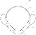
도 1은 본 발명의 일 실시예에 관련된 헤드셋의 개념도.
도 2 및 도 3은 리시버 홀더로부터 인출 가능하게 형성되는 리시버를 설명하기 위한 개념도.
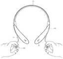
도 4는 헤드셋의 사용상태도.
도 5a는 본 발명의 다른 실시예에 관련된 헤드셋에서 리시버, 리시버 홀더 및 푸시버튼 스위치를 확대하여 나타낸 개념도.
도 5b는 도 5a에 도시된 푸시버튼 스위치의 회로도.
도 6은 입력부와 푸시버튼 스위치를 함께 구비하는 헤드셋을 나타내는 회로도.
도 7a는 본 발명의 또 다른 실시예에 관련된 헤드셋에서 리시버, 리시버 홀더 및 자기센서 스위치를 나타내는 개념도.
도 7b는 도 7a에 도시된 자기센서 스위치의 회로도.
도 8a는 본 발명의 또 다른 실시예에 관련된 헤드셋에서 리시버, 리시버 홀더 및 근접센서 스위치를 나타내는 개념도.
도 8b는 도 8a에 도시된 근접센서 스위치의 회로도.1 is a conceptual diagram of a headset according to an embodiment of the present invention;
Figs. 2 and 3 are conceptual diagrams for explaining a receiver which is drawably formed from a receiver holder; Fig.
Fig. 4 is a use state diagram of the headset. Fig.
FIG. 5A is an enlarged conceptual diagram of a receiver, a receiver holder, and a push button switch in a headset according to another embodiment of the present invention. FIG.
5B is a circuit diagram of the push-button switch shown in Fig. 5A. Fig.
6 is a circuit diagram showing a headset including an input unit and a push-button switch together;
7A is a conceptual diagram showing a receiver, a receiver holder, and a magnetic sensor switch in a headset according to another embodiment of the present invention.
FIG. 7B is a circuit diagram of the magnetic sensor switch shown in FIG. 7A. FIG.
8A is a conceptual view showing a receiver, a receiver holder, and a proximity sensor switch in a headset according to another embodiment of the present invention.
Fig. 8B is a circuit diagram of the proximity sensor switch shown in Fig. 8A. Fig.
이하, 본 발명에 관련된 헤드셋에 대하여 도면을 참조하여 보다 상세하게 설명한다. 본 명세서에서는 서로 다른 실시예라도 동일·유사한 구성에 대해서는 동일·유사한 참조번호를 부여하고, 그 설명은 처음 설명으로 갈음한다. 본 명세서에서 사용되는 단수의 표현은 문맥상 명백하게 다르게 뜻하지 않는 한, 복수의 표현을 포함한다. 또한, 이하의 설명에서 사용되는 구성요소에 대한 접미사 "모듈" 및 "부"는 명세서 작성의 용이함만이 고려되어 부여되거나 혼용되는 것으로서, 그 자체로 서로 구별되는 의미 또는 역할을 갖는 것은 아니다.Hereinafter, a headset according to the present invention will be described in detail with reference to the drawings. In the present specification, the same or similar reference numerals are given to different embodiments in the same or similar configurations. As used herein, the singular forms "a", "an" and "the" include plural referents unless the context clearly dictates otherwise. In addition, the suffix "module" and " part "for constituent elements used in the following description are given or mixed in consideration of ease of specification, and do not have their own meaning or role.
도 1은 본 발명의 일 실시예에 관련된 헤드셋(100)의 개념도이다.1 is a conceptual diagram of a
헤드셋(100)은 사용자가 머리에 쓰거나 목에 걸어 사용할 수 있도록 형성되며, 전기적으로 연결된 단말기(미도시)에서 전달된 전기 신호를 음향 신호로 전환하여 출력한다.The
헤드셋 본체(110)의 내부에는, 헤드셋(100)에 입력되는 사용자의 제어명령을 처리하거나 헤드셋(100)과 전기적으로 연결된 단말기를 제어하기 위한 전자부품들이 내장된다.Inside the headset
헤드셋(100)과 연결되는 단말기에는 이동 단말기가 포함되고, 이동 단말기에는 휴대폰, 스마트 폰(smart phone), 노트북 컴퓨터(laptop computer), 디지털방송용 단말기, PDA(Personal Digital Assistants), PMP(Portable Multimedia Player), 네비게이션, 슬레이트 PC(slate PC), 태블릿 PC(tablet PC), 울트라북(ultrabook) 등이 포함될 수 있다. 그러나, 본 명세서에 기재된 실시예에 따른 구성은 이동 단말기에만 적용 가능한 경우를 제외하면, 디지털 TV, 데스크탑 컴퓨터 등과 같은 고정 단말기에도 적용될 수도 있음을 본 기술분야의 당업자라면 쉽게 알 수 있을 것이다.A mobile phone, a smart phone, a laptop computer, a digital broadcasting terminal, a PDA (personal digital assistant), a portable multimedia player (PMP) ), Navigation, slate PCs, tablet PCs, ultrabooks, and the like. However, it will be understood by those skilled in the art that the configuration according to the embodiments described herein may be applied to a fixed terminal such as a digital TV, a desktop computer, and the like, unless the configuration is applicable only to a mobile terminal.
헤드셋(100)과 연결되는 단말기는 근거리 통신을 위한 근거리 통신 모듈을 구비할 수 있다. 근거리 통신(short range communication) 기술로 블루투스(Bluetooth), RFID(Radio Frequency Identification), 적외선 통신(Infrared Data Association; IrDA), UWB(Ultra Wideband), ZigBee, NFC(Near Field Communication) 등이 이용될 수 있다. 따라서 헤드셋(100)과 단말기는 블루투스 기술에 의해 무선으로 연결될 수 있다.The terminal connected to the
밴드(112)는 두 헤드셋 본체(110)를 물리적으로 연결할 뿐만 아니라, 두 헤드셋 본체(110)의 내부에 내장된 전자부품들을 전기적으로 연결시킨다. 사용자는 밴드(112)를 이용하여 헤드셋(100)을 신체에 거치시키고 사용할 수 있다.The
입력부(111)는 헤드셋(100) 또는 헤드셋(100)과 전기적으로 연결된 단말기를 조작하기 위한 제어명령을 입력받는다. 입력부(111)는 헤드셋 본체(110)의 적어도 일부 영역에 형성될 수 있다.The
도 2 및 도 3은 리시버 홀더(113)로부터 인출 가능하게 형성되는 리시버(120)를 설명하기 위한 개념도이고, 도 4는 헤드셋(100)의 사용상태도이다.2 and 3 are conceptual diagrams for explaining a
헤드셋(100)은 밴드(112)를 목에 걸어 사용하며, 리시버(120)를 리시버 홀더(113)에서 인출하여 귀에 삽입함으로써 사용자는 리시버(120)로부터 출력되는 음향을 들을 수 있다. 헤드셋(100)을 목에 건 상태에서 사용하면 헤드셋 본체(110)에 형성되는 입력부(111)가 사용자의 목 부분에 위치하므로 사용자의 시야에서 벗어나 조작이 불편하다. 본 발명은 이러한 불편함을 극복하고자 리시버 홀더(113)로부터 리시버(120)를 인출하는 동작에 의해 자동으로 제어명령이 입력되도록 이루어진다.The
헤드셋 본체(110)의 측면에는 전면의 입력부(111)와 또 다른 입력부(111')가 형성될 수 있다. 전면의 입력부(111)와 측면의 입력부(111')는 그 기능이 분리되어, 전면의 입력부(111)는 출력되는 음향을 재생 또는 정지하거나 단말기에 걸려온 전화를 수신하는 통화모드로 전환시키는 기능을 수행하고, 측면의 입력부(111')는 출력되는 음향의 볼륨(또는 음량)을 늘리거나 줄이는 기능을 수행할 수 있다.A
리시버(120)는 리시버 홀더(113)에 수납되거나 리시버 홀더(113)로부터 인출 가능하도록 형성된다. 사용자가 헤드셋(100)을 사용하지 않는 때에는 리시버(120)를 리시버 홀더(113)에 수납시키고, 헤드셋(100)을 사용하는 때에는 리시버(120)를 리시버 홀더(113)로부터 인출시킨다.The
리시버(120)는 케이블(121)에 의해 헤드셋 본체(110)와 연결되므로, 리시버(120)가 리시버 홀더(113)에 수납되거나 리시버 홀더(113)로부터 인출되는 것에 무관하게 리시버(120)와 헤드셋 본체(110)에 내장된 전자부품들은 서로 전기적으로 연결된 상태를 유지한다.The
리시버(120)가 리시버 홀더(113)에 수납되는 구조는 여러 가지가 있을 수 있다. 예를 들어, 리시버(120)와 리시버 홀더(113)에 인력이 작용하도록 각각 서로 다른 극을 갖는 자석이 구비되어, 자력에 의해 리시버(120)를 리시버 홀더(113)에 거치시킬 수 있다. 다른 구조로, 리시버(120)와 리시버 홀더(113) 중 어느 하나에 가이드 레일이 형성되고 다른 하나에 가이드 돌기가 형성되어, 리시버(120)를 리시버 홀더(113)에 결합시키는 구조가 있을 수 있다. 또 다른 구조로, 리시버(120)와 리시버 홀더(113) 어느 하나에 걸쇠가 형성되고 다른 하나에 걸이홈이 형성되어 리시버(120)를 리시버 홀더(113)에 거는 구조가 있을 수 있다.There are various structures in which the
스위치(130)는 리시버(120)의 수납 또는 인출을 감지하도록 리시버(120) 또는 리시버 홀더(113)에 설치된다. 스위치(130)는 리시버(120)의 수납 또는 인출에 의해 온/오프 상태가 전환되도록 형성된다.The
회로기판(미도시)은 단말기와 전기적으로 연결되어 전기적 신호를 처리하도록 헤드셋 본체(110)의 내부에 설치된다. 회로기판은 스위치(130)의 온/오프 상태 전환에 따라 헤드셋(100)과 연결된 단말기의 작동상태(functional condition)를 전환시키도록 스위치(130)와 전기적으로 연결된다. 회로기판은 단말기의 작동상태를 제어하므로 제어부로 통칭될 수 있다.A circuit board (not shown) is installed inside the
리시버(120)가 리시버 홀더(113)에서 인출되거나 리시버 홀더(113)에 수납되면, 스위치(130)가 온 상태에서 오프 상태로 전환되거나 오프 상태에서 온 상태로 전환되고, 스위치(130)의 전환에 따라 회로기판은 단말기의 적어도 일부 기능을 동작상태(active state)에서 유휴상태(idle state)로 전환시키거나 유휴상태에서 동작상태로 전환시킨다.When the
회로기판에 의해 작동상태가 전환되는 단말기의 기능은 통화, 통신, 음향출력이 될 수 있다. 예를 들어, 리시버 홀더(113)에 수납되어 있던 리시버(120)의 인출에 의해 스위치(130)가 온 상태로 전환되면, 회로기판은 단말기의 통화 기능을 동작상태로 전환시켜 수신된 전화를 받을 수 있다. 이에 따라, 사용자가 전화를 받기 위해 리시버 홀더(113)에서 리시버(120)를 인출하고 입력부(111)를 통해 단말기의 통화기능을 동작 상태로 전환하는 제어명령을 입력하는 2단계 과정이, 리시버 홀더(113)에서 리시버(120)를 인출하는 1단계 과정만으로 가능해진다.The function of the terminal whose operation state is switched by the circuit board can be call, communication, and sound output. For example, when the
다른 예로는, 리시버 홀더(113)에서 인출되어 있던 리시버(120)가 리시버 홀더(113)로 수납되어 스위치(130)가 오프되면, 회로기판은 단말기의 음향출력 기능을 동작상태에서 유휴상태로 전환시켜 리시버(120)의 음향 출력을 중지시킬 수 있다.As another example, when the
따라서 본원발명에 의하면 사용자는 헤드셋 본체(110)에 구비된 입력부(111)를 통해 헤드셋(100)에 별도의 제어명령을 입력하지 않더라도, 단말기와 연결된 헤드셋(100)의 리시버 홀더(113)에서 리시버(120)를 인출하거나 수납하는 동작만으로도 단말기를 조작할 수 있다.According to the present invention, therefore, even if a user does not input a separate control command to the
회로기판은 단말기의 작동상태를 전환시킨 후 다시 스위치(130)에서 리시버(120)의 수납 또는 인출에 의해 온/오프 상태가 전환되기 전까지 단말기의 이미 전환된 작동상태를 유지시킨다. 단말기의 전환된 작동상태를 유지시키지 않으면 걸려온 전화가 끊어지거나 출력되던 음향이 중지될 수 있으므로, 이러한 현상들을 방지하기 위한 것이다.The circuit board maintains the already switched operating state of the terminal until the ON / OFF state is switched by the receipt or withdrawal of the
회로기판은 복수의 스위치(130) 중 어느 일부의 스위치(130)의 온/오프 상태가 전환되어 단말기의 작동상태를 전환시킨 후 이어서 다른 일부의 스위치(130)도 동일하게 온/오프 상태가 전환되면 단말기의 이미 전환된 작동상태를 유지시킨다.On the circuit board, after the ON / OFF state of the
이는 단말기의 정상적인 이용을 위한 것으로, 도시한 바와 같이 두 개의 헤드셋 본체(110)가 밴드(112)에 의해 연결되고 각 헤드셋 본체(110)마다 리시버 홀더(113)와 리시버(120)를 구비하는 경우, 어느 하나의 리시버(120)를 리시버 홀더(113)로부터 인출하는 동작에 의해 스위치(130)의 온/오프 상태가 전환되면 회로기판은 단말기의 작동상태를 전환시킨다. 그러나, 다른 하나의 리시버(120)를 리시버 홀더(113)로부터 인출하는 동작이 곧바로 이어져 스위치(130)의 온/오프 상태가 전환되더라도 단말기의 이미 전환된 작동상태는 유지되어 사용자는 단말기를 정상적으로 이용할 수 있다.As shown in the figure, when two
이에 따라, 리시버(120)가 헤드셋(100)에 짝수로 구비되어 스위치(130)의 온/오프 상태 전환을 짝수 회 반복하면, 유휴상태에서 동작상태로 전환되었던 단말기가 다시 유휴상태로 전환되거나, 동작상태에서 유휴상태로 전환되었던 단말기가 다시 동작상태로 전환되는 것을 방지할 수 있다.Accordingly, if the
예를 들어, 단말기에 전화가 걸려온 경우 어느 하나의 리시버(120)를 리시버 홀더(113)로부터 인출하는 동작에 의해 단말기의 통화기능을 동작상태로 전환시키면 통화가 가능하다. 그러나, 만일 다른 하나의 리시버(120)를 리시버 홀더(113)로부터 인출하는 동작에 의해 단말기의 통화기능을 유휴상태로 다시 전환시키면 통화가 채 끝나기도 전에 통화기능이 종료되게 된다. 따라서, 회로기판은 단말기의 정상적인 이용을 위해 두 스위치(130)에서 어느 하나의 온/오프 상태가 전환되고 이어서 다른 하나도 상기 어느 하나와 동일하게 전환되더라도 단말기의 작동상태를 한 번만 전환시킴으로써 걸려온 전화가 중간에 끊어지거나 출력되던 음향이 중지되는 것을 방지한다.For example, when a call is received from a terminal, a call can be made by switching a call function of the terminal to an operating state by an operation of taking out one of the
마찬가지로, 모든 리시버(120)가 인출된 상태로 통화가 종료되고 인출되어 있던 리시버(120)들 중 어느 하나를 리시버 홀더(113)에 수납하면 통화기능이 동작상태에서 유휴상태로 전환된다. 그러나, 이어서 다른 하나의 리시버(120)를 리시버 홀더(113)에 수납하더라도 다시 단말기의 통화기능이 동작상태로 전환되지는 않는다.Likewise, when any one of the
헤드셋(100)은 리시버(120)를 리시버 홀더(113)로부터 인출된 상태에서 사용할 수 있고, 리시버(120)를 리시버 홀더(113)에 수납한 상태에서는 사용할 수 없다. 리시버(120)가 모두 리시버 홀더(113)에서 인출된 상태에서 단말기의 작동상태 전환은 헤드셋 본체(110)에 구비된 입력부(111)에 의해 이루어진다.The
입력부(111)는 스위치(130)와 별개로 사용자로부터 단말기의 통화상태를 유휴상태에서 동작상태로 전환시키는 제어명령을 입력받는다. 입력부(111)는, 모든 리시버(120)가 리시버 홀더(113)로부터 인출된 상태에서 사용자가 단말기의 통화기능, 통신기능, 음향출력기능을 제어하고자 하는 경우 사용자로부터 제어명령을 입력받을 수 있으나, 반드시 이에 한정되는 것은 아니고 리시버(120)가 리시버 홀더(113)에 수납된 상태에서도 제어명령을 입력받을 수 있다.The
모든 리시버(120)가 리시버 홀더(113)로부터 인출된 상태에서 단말기에 전화가 걸려오면, 사용자는 이미 모든 리시버(120)가 귀에 삽입되어 있으므로 스위치(130)를 전환시키기 위해 리시버(120)를 리시버 홀더(113)에 수납하면 정상적으로 통화가 이루어질 수 없다. 따라서, 이 경우에는 헤드셋 본체(110)에 구비된 입력부(111)를 조작하여 단말기의 통화기능을 동작상태로 전환시킬 수 있다.When all of the
따라서, 입력부(111)와 스위치(130)는 사용자의 편의에 따라 제어명령을 입력하기 위해 사용될 수 있으며, 서로 헤드셋과 단말기의 제어를 보완하도록 이루어진다.Therefore, the
도 5a는 본 발명의 다른 실시예에 관련된 헤드셋에서 리시버(220), 리시버 홀더(213) 및 푸시버튼 스위치(230)를 확대하여 나타낸 개념도이고, 도 5b는 도 5a에 도시된 푸시버튼 스위치(230)의 회로도이다.5A is a conceptual view showing an enlarged view of a
스위치(230)는, 리시버 홀더(213)의 적어도 일 영역에서 돌출되도록 형성되어 리시버(220)의 수납 또는 인출에 따라 푸시되거나 복원되는 푸시버튼 스위치(230)를 포함한다. 푸시버튼 스위치(230)는 리시버 홀더(213) 수납되는 리시버(220)와 접촉되도록 배치되어, 리시버 홀더(213)에 수납되는 리시버(220)에 의해 푸시되고, 리시버(220)의 인출시 푸시되기 전의 상태로 복원된다.The
푸시버튼 스위치(230)는 푸시 또는 복원 여부에 따라 온/오프 상태가 전환된다. 리시버(220)가 리시버 홀더(213)에 수납됨에 따라 푸시버튼 스위치(230)가 푸시되어 오프 상태로 전환되면 회로기판은 단말기의 적어도 일부 기능을 유휴상태로 전환시킨다. 반대로 리시버(220)가 리시버 홀더(213)로부터 인출됨에 따라 푸시버튼 스위치(230)가 복원되어 온 상태로 전환되면 회로기판은 단말기의 적어도 일부 기능을 동작상태로 전환시킨다.The push-
예를 들어, 리시버 홀더(213)에서 리시버(220)가 인출되면 푸시버튼 스위치(230)가 복원된다. 이에 따라 푸시버튼 스위치(230)는 온 상태로 전환된다. 그리고 회로기판의 제어에 의해 단말기는 통화기능이 동작상태로 전환되어 사용자는 전화를 받을 수 있다.For example, when the
반대로, 리시버 홀더(213)에 리시버(220)가 수납되면 푸시버튼 스위치(230)가 푸시된다. 이에 따라 푸시버튼 스위치(230)는 오프 상태로 전환된다. 그리고 회로기판의 제어에 의해 단말기는 통화기능이 유휴상태로 전환되어 전화는 끊긴다. 통신기능이나 음향출력기능도 통화기능과 마찬가지이다.Conversely, when the
도 6은 입력부(211)와 푸시버튼 스위치(230)를 함께 구비하는 헤드셋을 나타내는 회로도이다.6 is a circuit diagram showing a headset including an
입력부(211)와 스위치(230) 모두 회로기판(240)에 구비된 프로그래머블 인아웃 포트(241)와 연결되고, 온/오프 상태가 전환되도록 형성된다. 다만, 입력부(211)는 사용자의 능동적인 제어명령의 입력에 의해 온/오프 상태가 전환되고, 스위치(230)는 리시버(220)의 수납 여부에 따라 온/오프 상태가 전환된다는 차이가 있다.Both the
입력부(211)와 스위치(230) 중 어느 하나라도 온/오프 상태가 전환되면 프로그래머블 인아웃 포트(241)에 신호가 전달되고, 회로기판(240)은 신호를 인식하여 전화를 받거나 음향출력상태를 전환하는 등 단말기(미도시)의 작동상태를 전환시킨다.When either the
도 7a는 본 발명의 다른 실시예에 관련된 헤드셋에서 리시버(320), 리시버 홀더(313) 및 자기센서 스위치(330)를 나타내는 개념도이고, 도 7b는 도 7a에 도시된 자기센서 스위치(330)의 회로도이다.7A is a conceptual view showing a
도 7에 도시된 헤드셋은 스위치(330)가 온/오프되는 다른 구조를 갖는다. 리시버(320)는 리시버 홀더(313)를 마주하는 부분에 자석(322)을 구비하고, 스위치(330)는 자석의 자기장 영역 내에 있는지 여부에 따라 온/오프 상태가 전환되도록 형성되는 자기센서 스위치(330)를 포함한다.The headset shown in Fig. 7 has another structure in which the
리시버(320)가 리시버 홀더(313)에 수납되면, 자석(322)과 자기센서 스위치(330)가 가까워지므로 자기센서 스위치(330)는 자석의 자기장 영역 내에 위치하게 된다. 이에 따라 자기센서 스위치(330)는 온 상태에서 오프 상태로 전환되고, 자기센서 스위치(330)와 전기적으로 연결된 회로기판(미도시)은 단말기의 적어도 일부 기능을 동작상태에서 유휴상태로 전환시킨다.When the
반대로 리시버(320)가 리시버 홀더(313)에서 인출되면, 리시버(320)의 자석과 자기센서 스위치(330)가 멀어지므로 자기센서 스위치(330)는 자석의 자기장 영역을 벗어나게 된다. 이에 따라 자기센서 스위치(330)는 오프 상태에서 온 상태로 전환되고, 자기센서 스위치(330)와 전기적으로 연결된 회로기판은 단말기의 적어도 일부 기능을 유휴상태에서 동작상태로 전환시킨다.Conversely, when the
회로기판에 의해 전환되는 단말기의 기능은 이미 설명한 바와 마찬가지로 통화기능, 통신기능, 음향출력기능 등이 될 수 있다.The function of the terminal, which is switched by the circuit board, may be a call function, a communication function, an audio output function, and the like as described above.
따라서, 사용자는 편의에 따라 입력부(211)와 스위치(230) 중 어느 하나를 이용하여 헤드셋과 단말기를 제어할 수 있다.Accordingly, the user can control the headset and the terminal using either the
도 8a는 본 발명의 또 다른 실시예에 관련된 헤드셋에서 리시버(420), 리시버 홀더(413) 및 근접센서 스위치(430)를 나타내는 개념도이고, 도 8b는 도 8a에 도시된 근접센서 스위치(430)의 회로도이다.8A is a conceptual view showing a
스위치(430)는 근접한 감지영역 내의 대상물 유무에 따라 리시버(420)가 리시버 홀더(413)에 수납되거나 인출되었음을 감지하여 온/오프 상태가 전환되도록 형성되는 근접센서 스위치(430)를 포함한다.The
리시버(420)가 리시버 홀더(413)에 수납됨에 따라 근접센서 스위치(430)가 감지영역 내의 리시버(420)를 감지하여 오프 상태로 전환되면 회로기판은 단말기의 적어도 일부 기능을 유휴상태로 전환시킨다.When the
반대로, 리시버(420)가 리시버 홀더(413)에서 인출됨에 따라 근접센서 스위치(430)가 감지영역 내에서 리시버(420)를 감지하지 못하여 온 상태로 전환되면 회로기판은 단말기의 적어도 일부 기능을 동작상태로 전환시킨다.On the contrary, if the
회로기판에 의해 전환되는 단말기의 기능은 이미 설명한 바와 마찬가지로 통화기능, 통신기능, 음향출력기능 등이 될 수 있다.The function of the terminal, which is switched by the circuit board, may be a call function, a communication function, an audio output function, and the like as described above.
이상에서 설명된 헤드셋은 상기 설명된 실시예들의 구성과 방법에 한정되는 것이 아니라, 상기 실시예들은 다양한 변형이 이루어질 수 있도록 각 실시예들의 전부 또는 일부가 선택적으로 조합되어 구성될 수도 있다.The above-described headset is not limited to the configuration and method of the above-described embodiments, but all or a part of the embodiments may be selectively combined so that various modifications may be made to the embodiments.
Claims (16)
Translated fromKorean음향을 출력하도록 형성되고, 자석을 구비하여 상기 음향출력장치의 적어도 일부와 자력에 의해 착탈 가능하도록 이루어지는 리시버;
상기 리시버의 착탈을 감지하도록 상기 자석의 자기장 영역 내에 있는지 여부를 감지하는 자기센서; 및
상기 자기센서에서 감지되는 상기 리시버의 착탈 여부에 따라 상기 외부 단말기의 작동상태를 전환시키는 제어부를 포함하고,
분리되어 있던 상기 리시버를 통한 음향의 출력 중 상기 자기센서에서 상기 리시버의 결합이 감지되면, 상기 제어부는 상기 외부 단말기의 작동상태를 전환하여 음향의 출력을 정지시키며,
상기 제어부는 상기 외부 단말기의 작동상태를 전환시킨 후 다시 상기 자기센서에서 상기 리시버의 착탈을 감지하기 전까지 상기 외부 단말기의 이미 전환된 작동상태를 유지시키는 것을 특징으로 하는 음향출력장치.1. An audio output apparatus which is formed to be worn on a head or a neck and is capable of wireless communication with an external terminal,
A receiver which is formed to output sound and which is provided with a magnet so as to be removable by magnetic force with at least a part of the sound output apparatus;
A magnetic sensor for detecting whether or not the magnet is in a magnetic field region of the magnet so as to detect detachment of the receiver; And
And a controller for switching the operating state of the external terminal according to whether the receiver sensed by the magnetic sensor is attached or detached,
The control unit switches the operation state of the external terminal to stop the output of the sound when the coupling of the receiver is detected in the magnetic sensor among the outputs of the sound through the separated receiver,
Wherein the control unit maintains the already switched operating state of the external terminal until the magnetic sensor senses detachment of the receiver after switching the operating state of the external terminal.
음향을 출력하도록 형성되고, 자석을 구비하여 상기 음향출력장치의 적어도 일부와 자력에 의해 착탈 가능하도록 이루어지는 리시버;
상기 리시버의 착탈을 감지하도록 상기 자석의 자기장 영역 내에 있는지 여부를 감지하는 자기센서; 및
상기 자기센서에서 감지되는 상기 리시버의 착탈 여부에 따라 상기 외부 단말기의 작동상태를 전환시키는 제어부를 포함하고,
분리되어 있던 상기 리시버를 통한 음향의 출력 중 상기 자기센서에서 상기 리시버의 결합이 감지되면, 상기 제어부는 상기 외부 단말기의 작동상태를 전환하여 음향의 출력을 정지시키며,
상기 제어부는 복수의 자기센서 중 어느 일부 자기센서에서 상기 리시버의 착탈이 감지되어 상기 외부 단말기의 작동상태를 전환시킨 후 이어서 다른 일부 자기센서에서 상기 리시버의 착탈이 감지되면 상기 외부 단말기의 이미 전환된 작동상태를 유지시키는 것을 특징으로 하는 음향출력장치.1. An audio output apparatus which is formed to be worn on a head or a neck and is capable of wireless communication with an external terminal,
A receiver which is formed to output sound and which is provided with a magnet so as to be removable by magnetic force with at least a part of the sound output apparatus;
A magnetic sensor for detecting whether or not the magnet is in a magnetic field region of the magnet so as to detect detachment of the receiver; And
And a controller for switching the operating state of the external terminal according to whether the receiver sensed by the magnetic sensor is attached or detached,
The control unit switches the operation state of the external terminal to stop the output of the sound when the coupling of the receiver is detected in the magnetic sensor among the outputs of the sound through the separated receiver,
When the detachment / removal of the receiver is sensed by a certain magnetic sensor among the plurality of magnetic sensors and the operation state of the external terminal is detected and then detachment of the receiver is detected by another magnetic sensor, Thereby maintaining the operating state.
상기 제어부는 상기 자기센서에서 감지되는 상기 리시버의 착탈에 근거하여 상기 외부 단말기의 통화상태, 통신상태 및 음향출력상태 중 적어도 하나를 전환시키는 것을 특징으로 하는 음향출력장치.10. The method of claim 1 or 9,
Wherein the controller switches at least one of a call state, a communication state, and an acoustic output state of the external terminal based on detachment of the receiver sensed by the magnetic sensor.
상기 음향출력장치는 사용자의 제어명령을 입력받는 입력부를 더 포함하고,
상기 제어부는 상기 리시버가 상기 음향출력장치의 적어도 일부로부터 분리된 상태에서 상기 외부 단말기에 전화가 수신되면, 상기 입력부를 통해 인가되는 사용자의 제어명령에 근거하여 상기 외부 단말기의 통화기능을 동작시키는 것을 특징으로 하는 음향출력장치.10. The method of claim 1 or 9,
Wherein the sound output apparatus further includes an input unit for receiving a user's control command,
The control unit operates the call function of the external terminal on the basis of a control command of a user applied through the input unit when a call is received to the external terminal in a state where the receiver is separated from at least a part of the sound output apparatus Wherein the sound output device comprises:
상기 외부 단말기에 전화가 수신된 상태에서 상기 자기센서에서 상기 리시버의 분리가 감지되면, 상기 제어부는 상기 수신된 전화를 받도록 상기 외부 단말기의 통화기능을 동작시키는 것을 특징으로 하는 음향출력장치.10. The method of claim 1 or 9,
Wherein the control unit operates the call function of the external terminal to receive the received call when the reception of the receiver is detected by the magnetic sensor while the telephone is received in the external terminal.
통화 중 상기 자기센서에서 상기 리시버의 결합이 감지되면, 상기 제어부는 통화 중이던 전화를 종료시키도록 상기 외부 단말기의 통화기능을 유휴상태로 전환시키는 것을 특징으로 하는 음향출력장치.10. The method of claim 1 or 9,
Wherein when the coupling of the receiver is detected by the magnetic sensor during a call, the control unit switches the call function of the external terminal to the idle state so as to terminate the call during the call.
상기 음향출력장치는,
신체에 착용 가능한 밴드에 의해 서로 물리적, 전기적으로 연결되고, 내부에 전자부품들이 내장되는 두 본체;
상기 리시버를 수납하도록 이루어지며, 상기 두 본체의 단부에 각각 형성되는 리시버 홀더; 및
상기 본체로부터 돌출되어 상기 리시버에 연결되는 케이블을 더 포함하는 것을 특징으로 하는 음향출력장치.10. The method of claim 1 or 9,
The sound output apparatus includes:
Two bodies physically and electrically connected to each other by a band that can be worn by the body and having electronic parts embedded therein;
A receiver holder formed to receive the receiver, the receiver holder being formed at each end of the two bodies; And
And a cable projecting from the main body and connected to the receiver.
상기 두 본체는 서로 대칭적으로 형성되고, 상기 음향출력장치를 목에 착용했을 때 사용자의 목을 감싸는 것을 특징으로 하는 음향출력장치.15. The method of claim 14,
Wherein the two main bodies are formed symmetrically with respect to each other and surround the user's neck when the sound output device is worn on the neck.
상기 음향출력장치는 리시버 홀더를 더 포함하고,
상기 리시버 홀더에는 상기 리시버에 구비된 상기 자석과 다른 극을 갖는 자석이 설치되는 것을 특징으로 하는 음향출력장치.10. The method of claim 1 or 9,
The sound output apparatus further includes a receiver holder,
Wherein the receiver holder is provided with a magnet having a polarity different from that of the magnet provided in the receiver.
Priority Applications (1)
| Application Number | Priority Date | Filing Date | Title |
|---|---|---|---|
| KR1020130076577AKR101521938B1 (en) | 2013-07-01 | 2013-07-01 | Headset |
Applications Claiming Priority (1)
| Application Number | Priority Date | Filing Date | Title |
|---|---|---|---|
| KR1020130076577AKR101521938B1 (en) | 2013-07-01 | 2013-07-01 | Headset |
Publications (2)
| Publication Number | Publication Date |
|---|---|
| KR20150003555A KR20150003555A (en) | 2015-01-09 |
| KR101521938B1true KR101521938B1 (en) | 2015-05-20 |
Family
ID=52476236
Family Applications (1)
| Application Number | Title | Priority Date | Filing Date |
|---|---|---|---|
| KR1020130076577AActiveKR101521938B1 (en) | 2013-07-01 | 2013-07-01 | Headset |
Country Status (1)
| Country | Link |
|---|---|
| KR (1) | KR101521938B1 (en) |
Cited By (2)
| Publication number | Priority date | Publication date | Assignee | Title |
|---|---|---|---|---|
| KR101704648B1 (en) | 2015-12-28 | 2017-02-22 | 김재범 | Headset for measuring body composition and wireless charging |
| WO2018128299A1 (en)* | 2017-01-04 | 2018-07-12 | Lg Electronics Inc. | Portable sound equipment |
Families Citing this family (4)
| Publication number | Priority date | Publication date | Assignee | Title |
|---|---|---|---|---|
| US10097912B2 (en) | 2015-03-27 | 2018-10-09 | Intel Corporation | Intelligent switching between air conduction speakers and tissue conduction speakers |
| US9788097B2 (en) | 2016-01-29 | 2017-10-10 | Big O LLC | Multi-function bone conducting headphones |
| KR101848669B1 (en) | 2016-12-26 | 2018-05-28 | 엘지전자 주식회사 | Wireless sound equipment |
| KR101876987B1 (en)* | 2016-12-30 | 2018-07-11 | 크레신 주식회사 | Neck-band type earphone |
Citations (3)
| Publication number | Priority date | Publication date | Assignee | Title |
|---|---|---|---|---|
| KR200241011Y1 (en)* | 2001-03-28 | 2001-10-10 | 금왕씨앤씨 주식회사 | A call turning system of a earphone for a handsfree |
| KR20050096301A (en)* | 2004-03-30 | 2005-10-06 | 에스케이텔레텍주식회사 | Wireless earphone |
| KR101144271B1 (en)* | 2005-09-13 | 2012-05-11 | 삼성전자주식회사 | Ear microphone for portable terminal |
- 2013
- 2013-07-01KRKR1020130076577Apatent/KR101521938B1/enactiveActive
Patent Citations (3)
| Publication number | Priority date | Publication date | Assignee | Title |
|---|---|---|---|---|
| KR200241011Y1 (en)* | 2001-03-28 | 2001-10-10 | 금왕씨앤씨 주식회사 | A call turning system of a earphone for a handsfree |
| KR20050096301A (en)* | 2004-03-30 | 2005-10-06 | 에스케이텔레텍주식회사 | Wireless earphone |
| KR101144271B1 (en)* | 2005-09-13 | 2012-05-11 | 삼성전자주식회사 | Ear microphone for portable terminal |
Cited By (3)
| Publication number | Priority date | Publication date | Assignee | Title |
|---|---|---|---|---|
| KR101704648B1 (en) | 2015-12-28 | 2017-02-22 | 김재범 | Headset for measuring body composition and wireless charging |
| WO2018128299A1 (en)* | 2017-01-04 | 2018-07-12 | Lg Electronics Inc. | Portable sound equipment |
| US10491983B2 (en) | 2017-01-04 | 2019-11-26 | Lg Electronics Inc. | Portable sound equipment |
Also Published As
| Publication number | Publication date |
|---|---|
| KR20150003555A (en) | 2015-01-09 |
Similar Documents
| Publication | Publication Date | Title |
|---|---|---|
| EP3591987B1 (en) | Method for controlling earphone switching, earphone, and earphone system | |
| KR101521938B1 (en) | Headset | |
| EP2645737B1 (en) | Apparatus and method for interfacing earphone | |
| US7627289B2 (en) | Wireless stereo headset | |
| US8188851B2 (en) | Wake-up system and method for an electronic apparatus | |
| KR101433166B1 (en) | How to pair a bluetooth headset and its multipoint | |
| US20120300962A1 (en) | Solar Powered Wireless Bluetooth Stereo Speaker With connectivity To MP3 Player | |
| CA2927141C (en) | Pulsed input push-to-talk wireless adapter systems and methods | |
| US10630826B2 (en) | Information processing device | |
| KR101790042B1 (en) | Earphone system And Portable Device supporting the same, and Operation Method of Earphone based on the same | |
| EP2837206B1 (en) | Pulsed input push-to-talk systems, methods and apparatus | |
| US9374657B2 (en) | Bluetooth transceiver, wired headphone module, and mobile device module | |
| KR20130066880A (en) | Detecting system for connecting of earphone and electric device supporting the same | |
| GB2420048A (en) | Bluetooth headset and bluetooth device connectable to audio equipment | |
| KR100936393B1 (en) | Stereo bluetooth headset | |
| US20140254818A1 (en) | System and method for automatically switching operational modes in a bluetooth earphone | |
| EP3186975B1 (en) | Loudspeaker audio accessory for a communication device | |
| CN105554631A (en) | Audio switching method and device, and electronic device | |
| US8229514B2 (en) | DECT wireless hands-free communication apparatus | |
| JP2012191611A (en) | Communication device and changeover method | |
| KR20160147498A (en) | Detachable mono earset | |
| KR20160116555A (en) | Speaker mounted by headset and headset assembly having the same | |
| CN203746219U (en) | Wireless microphone with home appliance remote control function | |
| KR200356181Y1 (en) | Compatible multi-functional earphone device for portable handheld radiotelephone and audio apparatus | |
| JP2015100096A (en) | Earphone |
Legal Events
| Date | Code | Title | Description |
|---|---|---|---|
| PA0109 | Patent application | Patent event code:PA01091R01D Comment text:Patent Application Patent event date:20130701 | |
| PA0201 | Request for examination | Patent event code:PA02012R01D Patent event date:20140923 Comment text:Request for Examination of Application Patent event code:PA02011R01I Patent event date:20130701 Comment text:Patent Application | |
| PA0302 | Request for accelerated examination | Patent event date:20141001 Patent event code:PA03022R01D Comment text:Request for Accelerated Examination Patent event date:20130701 Patent event code:PA03021R01I Comment text:Patent Application | |
| PG1501 | Laying open of application | ||
| E902 | Notification of reason for refusal | ||
| PE0902 | Notice of grounds for rejection | Comment text:Notification of reason for refusal Patent event date:20150129 Patent event code:PE09021S01D | |
| E701 | Decision to grant or registration of patent right | ||
| PE0701 | Decision of registration | Patent event code:PE07011S01D Comment text:Decision to Grant Registration Patent event date:20150421 | |
| GRNT | Written decision to grant | ||
| PR0701 | Registration of establishment | Comment text:Registration of Establishment Patent event date:20150514 Patent event code:PR07011E01D | |
| PR1002 | Payment of registration fee | Payment date:20150515 End annual number:3 Start annual number:1 | |
| PG1601 | Publication of registration | ||
| FPAY | Annual fee payment | Payment date:20180424 Year of fee payment:4 | |
| PR1001 | Payment of annual fee | Payment date:20180424 Start annual number:4 End annual number:4 | |
| FPAY | Annual fee payment | Payment date:20190424 Year of fee payment:5 | |
| PR1001 | Payment of annual fee | Payment date:20190424 Start annual number:5 End annual number:5 | |
| PR1001 | Payment of annual fee | Payment date:20200424 Start annual number:6 End annual number:6 | |
| PR1001 | Payment of annual fee | Payment date:20240422 Start annual number:10 End annual number:10 |