KR101516899B1 - Power conversion apparatus for vehicle and Method for controling the same - Google Patents
Power conversion apparatus for vehicle and Method for controling the sameDownload PDFInfo
- Publication number
- KR101516899B1 KR101516899B1KR1020130168239AKR20130168239AKR101516899B1KR 101516899 B1KR101516899 B1KR 101516899B1KR 1020130168239 AKR1020130168239 AKR 1020130168239AKR 20130168239 AKR20130168239 AKR 20130168239AKR 101516899 B1KR101516899 B1KR 101516899B1
- Authority
- KR
- South Korea
- Prior art keywords
- power
- stage input
- output
- controller
- input unit
- Prior art date
- Legal status (The legal status is an assumption and is not a legal conclusion. Google has not performed a legal analysis and makes no representation as to the accuracy of the status listed.)
- Active
Links
- 238000006243chemical reactionMethods0.000titleclaimsabstractdescription35
- 238000000034methodMethods0.000titleclaimsdescription29
- 230000005669field effectEffects0.000claimsdescription11
- 229910044991metal oxideInorganic materials0.000claimsdescription10
- 150000004706metal oxidesChemical class0.000claimsdescription10
- 239000004065semiconductorSubstances0.000claimsdescription10
- 238000010248power generationMethods0.000claimsdescription8
- 230000001360synchronised effectEffects0.000claimsdescription6
- 230000000903blocking effectEffects0.000claims1
- 238000010586diagramMethods0.000description6
- 230000001965increasing effectEffects0.000description6
- 238000012986modificationMethods0.000description4
- 230000004048modificationEffects0.000description4
- 230000000694effectsEffects0.000description3
- PXHVJJICTQNCMI-UHFFFAOYSA-NNickelChemical compound[Ni]PXHVJJICTQNCMI-UHFFFAOYSA-N0.000description2
- 230000008859changeEffects0.000description2
- 239000000446fuelSubstances0.000description2
- 230000008569processEffects0.000description2
- HBBGRARXTFLTSG-UHFFFAOYSA-NLithium ionChemical compound[Li+]HBBGRARXTFLTSG-UHFFFAOYSA-N0.000description1
- 230000001133accelerationEffects0.000description1
- 230000008901benefitEffects0.000description1
- 230000005684electric fieldEffects0.000description1
- 230000005611electricityEffects0.000description1
- 238000004146energy storageMethods0.000description1
- 230000006872improvementEffects0.000description1
- 230000001939inductive effectEffects0.000description1
- 229910001416lithium ionInorganic materials0.000description1
- 239000000463materialSubstances0.000description1
- 229910052751metalInorganic materials0.000description1
- 239000002184metalSubstances0.000description1
- 229910052759nickelInorganic materials0.000description1
Images


Classifications
- H—ELECTRICITY
- H02—GENERATION; CONVERSION OR DISTRIBUTION OF ELECTRIC POWER
- H02M—APPARATUS FOR CONVERSION BETWEEN AC AND AC, BETWEEN AC AND DC, OR BETWEEN DC AND DC, AND FOR USE WITH MAINS OR SIMILAR POWER SUPPLY SYSTEMS; CONVERSION OF DC OR AC INPUT POWER INTO SURGE OUTPUT POWER; CONTROL OR REGULATION THEREOF
- H02M3/00—Conversion of DC power input into DC power output
- H02M3/22—Conversion of DC power input into DC power output with intermediate conversion into AC
- H02M3/24—Conversion of DC power input into DC power output with intermediate conversion into AC by static converters
- H02M3/28—Conversion of DC power input into DC power output with intermediate conversion into AC by static converters using discharge tubes with control electrode or semiconductor devices with control electrode to produce the intermediate AC
- H02M3/325—Conversion of DC power input into DC power output with intermediate conversion into AC by static converters using discharge tubes with control electrode or semiconductor devices with control electrode to produce the intermediate AC using devices of a triode or a transistor type requiring continuous application of a control signal
- H02M3/335—Conversion of DC power input into DC power output with intermediate conversion into AC by static converters using discharge tubes with control electrode or semiconductor devices with control electrode to produce the intermediate AC using devices of a triode or a transistor type requiring continuous application of a control signal using semiconductor devices only
- H02M3/33569—Conversion of DC power input into DC power output with intermediate conversion into AC by static converters using discharge tubes with control electrode or semiconductor devices with control electrode to produce the intermediate AC using devices of a triode or a transistor type requiring continuous application of a control signal using semiconductor devices only having several active switching elements
- H02M3/33576—Conversion of DC power input into DC power output with intermediate conversion into AC by static converters using discharge tubes with control electrode or semiconductor devices with control electrode to produce the intermediate AC using devices of a triode or a transistor type requiring continuous application of a control signal using semiconductor devices only having several active switching elements having at least one active switching element at the secondary side of an isolation transformer
- B—PERFORMING OPERATIONS; TRANSPORTING
- B60—VEHICLES IN GENERAL
- B60L—PROPULSION OF ELECTRICALLY-PROPELLED VEHICLES; SUPPLYING ELECTRIC POWER FOR AUXILIARY EQUIPMENT OF ELECTRICALLY-PROPELLED VEHICLES; ELECTRODYNAMIC BRAKE SYSTEMS FOR VEHICLES IN GENERAL; MAGNETIC SUSPENSION OR LEVITATION FOR VEHICLES; MONITORING OPERATING VARIABLES OF ELECTRICALLY-PROPELLED VEHICLES; ELECTRIC SAFETY DEVICES FOR ELECTRICALLY-PROPELLED VEHICLES
- B60L2210/00—Converter types
- B60L2210/10—DC to DC converters
- B60L2210/14—Boost converters
- B—PERFORMING OPERATIONS; TRANSPORTING
- B60—VEHICLES IN GENERAL
- B60L—PROPULSION OF ELECTRICALLY-PROPELLED VEHICLES; SUPPLYING ELECTRIC POWER FOR AUXILIARY EQUIPMENT OF ELECTRICALLY-PROPELLED VEHICLES; ELECTRODYNAMIC BRAKE SYSTEMS FOR VEHICLES IN GENERAL; MAGNETIC SUSPENSION OR LEVITATION FOR VEHICLES; MONITORING OPERATING VARIABLES OF ELECTRICALLY-PROPELLED VEHICLES; ELECTRIC SAFETY DEVICES FOR ELECTRICALLY-PROPELLED VEHICLES
- B60L2240/00—Control parameters of input or output; Target parameters
- B60L2240/40—Drive Train control parameters
- B60L2240/52—Drive Train control parameters related to converters
- B60L2240/527—Voltage
- B—PERFORMING OPERATIONS; TRANSPORTING
- B60—VEHICLES IN GENERAL
- B60L—PROPULSION OF ELECTRICALLY-PROPELLED VEHICLES; SUPPLYING ELECTRIC POWER FOR AUXILIARY EQUIPMENT OF ELECTRICALLY-PROPELLED VEHICLES; ELECTRODYNAMIC BRAKE SYSTEMS FOR VEHICLES IN GENERAL; MAGNETIC SUSPENSION OR LEVITATION FOR VEHICLES; MONITORING OPERATING VARIABLES OF ELECTRICALLY-PROPELLED VEHICLES; ELECTRIC SAFETY DEVICES FOR ELECTRICALLY-PROPELLED VEHICLES
- B60L2240/00—Control parameters of input or output; Target parameters
- B60L2240/40—Drive Train control parameters
- B60L2240/52—Drive Train control parameters related to converters
- B60L2240/529—Current
- H—ELECTRICITY
- H02—GENERATION; CONVERSION OR DISTRIBUTION OF ELECTRIC POWER
- H02M—APPARATUS FOR CONVERSION BETWEEN AC AND AC, BETWEEN AC AND DC, OR BETWEEN DC AND DC, AND FOR USE WITH MAINS OR SIMILAR POWER SUPPLY SYSTEMS; CONVERSION OF DC OR AC INPUT POWER INTO SURGE OUTPUT POWER; CONTROL OR REGULATION THEREOF
- H02M1/00—Details of apparatus for conversion
- H02M1/0067—Converter structures employing plural converter units, other than for parallel operation of the units on a single load
- H02M1/007—Plural converter units in cascade
- Y—GENERAL TAGGING OF NEW TECHNOLOGICAL DEVELOPMENTS; GENERAL TAGGING OF CROSS-SECTIONAL TECHNOLOGIES SPANNING OVER SEVERAL SECTIONS OF THE IPC; TECHNICAL SUBJECTS COVERED BY FORMER USPC CROSS-REFERENCE ART COLLECTIONS [XRACs] AND DIGESTS
- Y02—TECHNOLOGIES OR APPLICATIONS FOR MITIGATION OR ADAPTATION AGAINST CLIMATE CHANGE
- Y02T—CLIMATE CHANGE MITIGATION TECHNOLOGIES RELATED TO TRANSPORTATION
- Y02T10/00—Road transport of goods or passengers
- Y02T10/60—Other road transportation technologies with climate change mitigation effect
- Y02T10/72—Electric energy management in electromobility
Landscapes
- Engineering & Computer Science (AREA)
- Power Engineering (AREA)
- Dc-Dc Converters (AREA)
Abstract
Translated fromKoreanDescription
Translated fromKorean본 발명은 차량용 전력 변환 장치에 관한 것으로서, 더 상세하게는 2단 입력 회로를 구현하는 차량용 전력 변환 장치 및 이의 제어 방법에 대한 것이다.BACKGROUND OF THE INVENTION 1. Field of the Invention The present invention relates to a vehicle power conversion apparatus, and more particularly, to a vehicle power conversion apparatus implementing a two-stage input circuit and a control method thereof.
또한, 본 발명은 고전압 배터리 입력 전압을 일정 전압으로 승압한 후 고정 듀티를 제어하는 차량용 전력 변환 장치 및 이의 제어 방법에 대한 것이다.The present invention also relates to a power conversion apparatus for a vehicle and a control method thereof for boosting a high-voltage battery input voltage to a constant voltage and then controlling a fixed duty.
또한, 본 발명은 입력단측과 출력단측 회로를 스위칭 소자로 변경하여 손실을 줄임으로써 효율이 개선된 차량용 전력 변환 장치 및 이의 제어 방법에 대한 것이다.The present invention also relates to a power conversion device for a vehicle and a control method thereof, which are improved in efficiency by reducing an input side and an output side circuit to switching elements to reduce losses.
일반적으로, 친환경 차량은 엔진 및/또는 배터리의 전원으로 구동되는 구동모터로 구성되는 동력원이 구비된다. 따라서, 전륜에 상기의 동력원을 적절히 조합한 구조를 적용하여 차량의 출발시 및/또는 가속시에 배터리의 전압에 의해 동작되는 모터의 동력 보조로 연비 향상을 유도할 수 있는 차량을 말한다.Generally, the eco-friendly vehicle is provided with a power source composed of an engine and / or a drive motor driven by a power source of the battery. Accordingly, a structure in which the above-described power source is suitably combined to the front wheels is used to refer to a vehicle capable of inducing an improvement in fuel economy due to the power assist of the motor operated by the voltage of the battery at the start and / or acceleration of the vehicle.
친환경 차량에는 고전압 배터리의 전력을 정류하여 직류로 만드는 전력 변환 장치(LDC: Low DC/DC Converter)가 구비된다.The eco-friendly vehicle is provided with a power conversion device (LDC: Low DC / DC Converter) that rectifies the power of the high-voltage battery to make it into a direct current.
전력 변환 장치는 일반 직류(DC)를 스위칭시켜 교류(AC)로 만들고 이 교류를 코일, 트랜스, 커패시턴스 등을 이용해 승압 또는 강압한다. 이후, 다시 정류시켜 직류(DC)로 만들어, 각 전장 부하에서 사용되는 전압에 맞게 전기를 공급하는 역할을 한다.The power conversion device converts a normal direct current (DC) into an alternating current (AC), and boosts or reduces the alternating current by using a coil, a transformer, a capacitance, and the like. Thereafter, it is rectified again to make direct current (DC), and supplies electricity according to the voltage used in each electric field load.
이러한, 전력 변환 장치를 보여주는 도면이 도 1에 도시된다. 도 1을 참조하면, 고전압 입력단(110), 풀 브릿지 회로부(120), 변압기(140) 및 출력단(160) 등으로 구성된다.A diagram showing such a power conversion device is shown in Fig. Referring to FIG. 1, a high
그런데, 이러한 구성에 의할 경우 전력 변환 장치는 고전압 배터리 입력 전압 사양에 따라 파워 회로 부품(예를 들면, 구동 드라이버 회로, 변압기, 정류 다이오드 등을 들 수 있음)을 변경해야 하는 단점이 있었다. 부연하면, 차종별로 고전압 배터리 사용이 약 180V~310V, 약 200~410V, 약 170~280V, 약 132~206V 등 차종별로 고전압 배터리 사양이 상이하다. 이에 따라 파워 회로 부품들도 이원화되어 제조 및/또는 관리된다. 따라서, 재료비 및/또는 관리비가 증가하게 되었다.However, this configuration has a disadvantage in that the power converter has to be changed in accordance with the specifications of the high-voltage battery input voltage (for example, a drive circuit, a drive circuit, a transformer, a rectifier diode, etc.). In addition, high-voltage battery specifications are different for each model such as high-voltage battery use about 180V ~ 310V, about 200 ~ 410V, about 170 ~ 280V, about 132 ~ Accordingly, the power circuit components are also manufactured and / or managed in a binary manner. Therefore, the material cost and / or the management cost have increased.
또한, 일반적인 전력 변환 장치는 고전압 배터리가 저전압일 경우, 입력 전류가 증가하여 전력 변환 손실이 커서 효율 약 90% 이하 영역이 발생한다. 손실 대부분이 전류 도통시 열로 나타므로 전류를 줄여 발생되는 손실을 줄일 필요가 있다.Also, in a general power conversion device, when a high voltage battery is low voltage, an input current increases and power conversion loss is large, resulting in an efficiency of about 90% or less. Since most of the losses appear as heat during current conduction, it is necessary to reduce the current loss to reduce the losses.
또한, 일반적인 전력 변환 장치는 출력단(주로 정류 다이오드로 구성됨)에서 많은 손실이 발생하는 문제점이 있었다. 부연하면, 다이오드 도통시 손실은 전력 변환 장치 손실의 50%에 해당되며, 이는 전력 변환 장치 효율의 약 2%에 해당된다. 전력 변환 장치의 손실을 정의하면 다음식과 같다.In addition, a general power conversion apparatus has a problem that a large amount of loss occurs in an output stage (mainly composed of a rectifying diode). In addition, diode conduction losses account for 50% of power converter losses, which is about 2% of power converter efficiency. The loss of power converter is defined as follows.

여기서, Vd는 다이오드 순방향 전압 강하이며, I는 전류를 나타낸다.Where Vd is the diode forward voltage drop and I is the current.
본 발명은 위 배경기술에 따른 문제점을 해소하기 위해 제안된 것으로서, 고전압 배터리의 입력 전압 사양에 따른 파워 회로의 부품을 변경할 필요없이 동일하게 적용되는 공용화가 가능한 효율이 개선된 차량용 전력 변환 장치 및 이의 제어 방법을 제공하는데 그 목적이 있다.The present invention has been made in order to solve the above problems, and it is an object of the present invention to provide a power conversion device for a vehicle having an improved efficiency that can be used in common without the need to change parts of a power circuit according to an input voltage specification of a high- And a control method.
또한, 본 발명은 전력 변환 손실을 줄여 전력 변환 효율이 개선된 차량용 전력 변환 장치 및 이의 제어 방법을 제공하는데 다른 목적이 있다.It is another object of the present invention to provide a power conversion apparatus for a vehicle having improved power conversion efficiency by reducing power conversion loss and a control method thereof.
본 발명은 위에서 제시된 과제를 달성하기 위해, 고전압 배터리의 입력 전압 사양에 따른 파워 회로의 부품을 변경할 필요없이 동일하게 적용되는 공용화가 가능한 효율이 개선된 차량용 전력 변환 장치를 제공한다.The present invention provides a power conversion device for a vehicle having improved efficiency that can be used in common without the need to change parts of a power circuit according to an input voltage specification of a high voltage battery.
상기 차량용 전력 변환 장치는,The vehicular power converter includes:
출력 전원을 생성하는 출력 회로부;An output circuit for generating an output power;
상기 출력 전원을 센싱하고, 센싱된 출력 전원을 기준값과 비교하여 승압 전원의 생성을 위한 스위칭 제어를 수행하는 제 1 제어기;A first controller which senses the output power source and compares the sensed output power source with a reference value to perform switching control for generation of a boosted power source;
상기 스위칭 제어에 따라 배터리 전원을 입력받아 승압 전원을 생성하는 제 1 단 입력부;A first stage input unit for receiving a battery power according to the switching control to generate a step-up power supply;
상기 승압 전원을 다른 전원으로 변환하는 제 2 단 입력부; 및A second stage input unit for converting the step-up power supply to another power supply; And
상기 출력 전원을 위해 상기 다른 전원을 변환하는 변환부;를 포함하는 것을 특징으로 한다.And a conversion unit for converting the other power source for the output power source.
이때, 상기 제 1 단 입력부는 부스트 방식을 이용하여 상기 승압 전원을 생성하는 것을 특징으로 할 수 있다.In this case, the first stage input unit may generate the step-up power by using a boost method.
또한, 상기 제 1 단 입력부는, 인덕터; 상기 인덕터에 상기 승압 전원을 위해 상기 배터리 전원을 저장하게 하는 제 1 전력 스위칭 소자; 및 상기 승압 전원을 도통 또는 차단하는 제 2 전력 스위칭 소자;를 포함하는 것을 특징으로 할 수 있다.The first stage input unit may include an inductor; A first power switching device for allowing the inductor to store the battery power for the step-up power supply; And a second power switching device for turning on or off the step-up power supply.
또한, 상기 승압 전원은 상기 인덕터에 저장된 에너지와 상기 배터리 전원이 더해진 것을 특징으로 할 수 있다.The boosted power source may further include energy stored in the inductor and the battery power.
또한, 상기 제 1 전력 스위칭 소자 및 제 2 전력 스위칭 소자는 MOSFET(Metal Oxide Semiconductor Field Effect Transistor)인 것을 특징으로 할 수 있다.The first power switching device and the second power switching device may be MOSFETs (Metal Oxide Semiconductor Field Effect Transistors).
또한, 상기 제 2 단 입력부는 풀 브릿지(Full-Bridge) 회로이며, MOSFET(Metal Oxide Semiconductor Field Effect Transistor)로 이루어지는 것을 특징으로 할 수 있다.Also, the second stage input unit may be a full-bridge circuit, and may be a MOSFET (Metal Oxide Semiconductor Field Effect Transistor).
또한, 상기 제 2 단 입력부는 고정 듀티값을 이용하는 것을 특징으로 할 수 있다.In addition, the second stage input unit may use a fixed duty value.
또한, 상기 출력 회로부는 상기 제 2 단 입력단과 동기화되는 동기 정류 회로인 것을 특징으로 할 수 있다.The output circuit section may be a synchronous rectification circuit synchronized with the second stage input terminal.
또한, 상기 출력 회로부는 MOSFET(Metal Oxide Semiconductor Field Effect Transistor)인 것을 특징으로 할 수 있다.The output circuit may be a MOSFET (Metal Oxide Semiconductor Field Effect Transistor).
또한, 상기 동기화를 위해 상기 출력 회로부 또는 상기 출력 회로부를 온오프로 스위칭 제어하는 제 2 제어기를 포함할 수 있다.The controller may further include a second controller for switching the output circuit portion or the output circuit portion on and off for synchronization.
또한, 상기 제 1 제어기는, 상기 출력 전원을 센싱하는 센싱부; 센싱된 출력 전원을 기준값과 비교하는 비교기; 및 비교 결과에 따라 스위칭 제어를 수행하는 온오프 동작부;를 포함하는 것을 특징으로 할 수 있다.The first controller may include: a sensing unit sensing the output power; A comparator for comparing the sensed output power with a reference value; And an on-off operation unit for performing switching control according to the comparison result.
다른 한편으로, 본 발명의 다른 일실시예에는, 출력 전원을 센싱하는 출력 전원 센싱 단계; 센싱된 출력 전원을 기준값과 비교하는 비교 단계; 비교 결과에 따라 제 1 단 입력부에서 스위칭 제어를 수행하여 배터리 전원을 입력받아 승압 전원을 생성하는 승압 전원 생성 단계; 제 2 단 입력부에서 승압 전원을 변환하여 다른 전원을 생성하는 변환 단계; 및 상기 다른 전원으로부터 출력 회로부에서 상기 출력 전원으로 생성하는 출력 전원 생성 단계;를 포함하는 것을 특징으로 하는 차량용 전력 변환 장치의 제어 방법을 제공한다.On the other hand, another embodiment of the present invention includes an output power sensing step of sensing output power; A comparison step of comparing the sensed output power with a reference value; A step-up power generation step of generating a step-up power by receiving a battery power by performing switching control in a first stage input unit according to a comparison result; A converting step of converting the step-up power from the second-stage input unit to generate another power source; And an output power generation step of generating the output power from the output power circuit part from the other power source.
이때, 상기 승압 전원 생성 단계는 부스트 방식을 이용하여 상기 승압 전원을 생성하는 것을 특징으로 할 수 있다.In this case, the step-up power generation step may generate the step-up power by using a boost method.
또한, 상기 승압 전원 생성 단계는, 제 1 전력 스위칭 소자를 이용하여 배터리 전원을 인덕터에 저장하는 단계; 및 제 2 스위치를 이용하여 상기 승압 전원을 도통 또는 차단하는 단계;를 포함하는 것을 특징으로 할 수 있다.The step-up power generation step may include: storing battery power in an inductor using a first power switching device; And turning on or off the step-up power supply using a second switch.
또한, 상기 비교 단계는, 비교 결과에서 상기 출력 전원이 기준값보다 작으면 스위칭 제어를 수행하여 승압 전원을 생성하는 단계; 및 비교 결과에서 상기 출력 전원이 기준값이면 스위칭 제어를 수행하여 승압 전원을 생성하지 않는 단계;를 포함하는 것을 특징으로 할 수 있다.The comparing step may include: generating a step-up power by performing switching control if the output power is smaller than a reference value in a comparison result; And performing switching control if the output power is a reference value in a result of the comparison, thereby not generating a boosted power.
본 발명에 따르면, 2단 입력 회로를 적용함으로써 고전압 배터리의 입력 전압 사양에 따른 파워 회로의 부품을 변경할 필요없이 동일하게 적용되는 공용화가 가능하므로 개발비 및 관리비가 감소한다.According to the present invention, by applying the two-stage input circuit, it is possible to commonly apply the same without changing the parts of the power circuit according to the input voltage specification of the high voltage battery, thereby reducing the development cost and the management cost.
또한, 본 발명의 다른 효과로서는 1차 입력단에서 승압시켜 전류값을 낮게 함으로써 손실 감소로 효율이 상승할 수 있다는 점을 들 수 있다.Another advantage of the present invention is that the efficiency can be increased by reducing the loss by lowering the current value by boosting the voltage at the primary input terminal.
또한, 본 발명의 또 다른 효과로서는 1차 입력단에서 스위칭 소자를 적용함으로써 도통 손실이 낮아져 추가 손실감소로 효율이 상승할 수 있다는 점을 들 수 있다.In addition, as another effect of the present invention, application of the switching element at the primary input terminal lowers the conduction loss, thereby increasing the efficiency by reducing the additional loss.
또한, 본 발명의 또 다른 효과로서는 출력단에서도 스위칭 소자를 적용함으로써 정류시 손실감소로 효율이 상승할 수 있다는 점을 들 수 있다.Another effect of the present invention is that the efficiency can be increased by reducing the loss during rectification by applying the switching element even at the output stage.
또한, 본 발명의 또 다른 효과로서는 2단 입력 회로 및 스위칭 소자의 적용으로 전력 변환 장치 전체 효율이 향상되며, 최대 효율은 약 92%에서 96%로 향상되고, 평균 효율은 약 90%에서 95%로 향상된다는 점을 들 수 있다.As a further effect of the present invention, the overall efficiency of the power converter is improved by applying the two-stage input circuit and the switching device, the maximum efficiency is improved from about 92% to 96%, the average efficiency is about 90% to 95% As shown in Fig.
도 1은 일반적인 전력 변환 장치의 구성도이다.
도 2는 본 발명의 일실시예에 따른 전력 변환 장치(200)의 회로 블럭도이다.
도 3은 도 2에 도시된 전력 변환 장치(200)를 회로로 구현한 일예이다.
도 4는 도 2에 도시된 제 1 제어기(260)의 회로 블럭도이다.
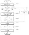
도 5는 본 발명의 일실시예에 따른 전력 변환 장치(200)의 제어 과정을 보여주는 흐름도이다.1 is a configuration diagram of a general power conversion apparatus.
2 is a circuit block diagram of a
FIG. 3 shows an example in which the
4 is a circuit block diagram of the
5 is a flowchart illustrating a control process of the
본 발명은 다양한 변경을 가할 수 있고 여러 가지 실시예를 가질 수 있는바, 특정 실시예들을 도면에 예시하고 상세한 설명에 구체적으로 설명하고자 한다. 그러나 이는 본 발명을 특정한 실시 형태에 대해 한정하려는 것이 아니며, 본 발명의 사상 및 기술 범위에 포함되는 모든 변경, 균등물 내지 대체물을 포함하는 것으로 이해되어야 한다.While the invention is susceptible to various modifications and alternative forms, specific embodiments thereof are shown by way of example in the drawings and will herein be described in detail. It is to be understood, however, that the invention is not to be limited to the specific embodiments, but includes all modifications, equivalents, and alternatives falling within the spirit and scope of the invention.
본 발명은 다양한 변경을 가할 수 있고 여러 가지 실시예를 가질 수 있는바, 특정 실시예들을 도면에 예시하고 상세한 설명에 구체적으로 설명하고자 한다. 그러나 이는 본 발명을 특정한 실시 형태에 대해 한정하려는 것이 아니며, 본 발명의 사상 및 기술 범위에 포함되는 모든 변경, 균등물 내지 대체물을 포함하는 것으로 이해되어야 한다.While the invention is susceptible to various modifications and alternative forms, specific embodiments thereof are shown by way of example in the drawings and will herein be described in detail. It is to be understood, however, that the invention is not to be limited to the specific embodiments, but includes all modifications, equivalents, and alternatives falling within the spirit and scope of the invention.
각 도면을 설명하면서 유사한 참조부호를 유사한 구성요소에 대해 사용한다.Like reference numerals are used for similar elements in describing each drawing.
제 1, 제 2등의 용어는 다양한 구성요소들을 설명하는데 사용될 수 있지만, 상기 구성요소들은 상기 용어들에 의해 한정되어서는 안 된다. 상기 용어들은 하나의 구성요소를 다른 구성요소로부터 구별하는 목적으로만 사용된다.The terms first, second, etc. may be used to describe various components, but the components should not be limited by the terms. The terms are used only for the purpose of distinguishing one component from another.
예를 들어, 본 발명의 권리 범위를 벗어나지 않으면서 제 1 구성요소는 제 2 구성요소로 명명될 수 있고, 유사하게 제 2 구성요소도 제 1 구성요소로 명명될 수 있다. "및/또는" 이라는 용어는 복수의 관련된 기재된 항목들의 조합 또는 복수의 관련된 기재된 항목들 중의 어느 항목을 포함한다.For example, without departing from the scope of the present invention, the first component may be referred to as a second component, and similarly, the second component may also be referred to as a first component. The term "and / or" includes any combination of a plurality of related listed items or any of a plurality of related listed items.
다르게 정의되지 않는 한, 기술적이거나 과학적인 용어를 포함해서 여기서 사용되는 모든 용어들은 본 발명이 속하는 기술 분야에서 통상의 지식을 가진 자에 의해 일반적으로 이해되는 것과 동일한 의미가 있다.Unless otherwise defined, all terms used herein, including technical or scientific terms, have the same meaning as commonly understood by one of ordinary skill in the art to which this invention belongs.
일반적으로 사용되는 사전에 정의되어 있는 것과 같은 용어들은 관련 기술의 문맥상 가지는 의미와 일치하는 의미가 있는 것으로 해석되어야 하며, 본 출원에서 명백하게 정의하지 않는 한, 이상적이거나 과도하게 형식적인 의미로 해석되지 않아야 한다. 각 도면을 설명하면서 유사한 참조부호를 유사한 구성요소에 대해 사용한다.Terms such as those defined in commonly used dictionaries are to be interpreted as having a meaning consistent with the meaning in the context of the relevant art and are to be construed as ideal or overly formal in meaning unless explicitly defined in the present application Should not. Like reference numerals are used for similar elements in describing each drawing.
제 1, 제 2등의 용어는 다양한 구성요소들을 설명하는데 사용될 수 있지만, 상기 구성요소들은 상기 용어들에 의해 한정되어서는 안 된다. 상기 용어들은 하나의 구성요소를 다른 구성요소로부터 구별하는 목적으로만 사용된다.The terms first, second, etc. may be used to describe various components, but the components should not be limited by the terms. The terms are used only for the purpose of distinguishing one component from another.
예를 들어, 본 발명의 권리 범위를 벗어나지 않으면서 제 1 구성요소는 제 2 구성요소로 명명될 수 있고, 유사하게 제 2 구성요소도 제 1 구성요소로 명명될 수 있다. "및/또는" 이라는 용어는 복수의 관련된 기재된 항목들의 조합 또는 복수의 관련된 기재된 항목들 중의 어느 항목을 포함한다.For example, without departing from the scope of the present invention, the first component may be referred to as a second component, and similarly, the second component may also be referred to as a first component. The term "and / or" includes any combination of a plurality of related listed items or any of a plurality of related listed items.
다르게 정의되지 않는 한, 기술적이거나 과학적인 용어를 포함해서 여기서 사용되는 모든 용어들은 본 발명이 속하는 기술 분야에서 통상의 지식을 가진 자에 의해 일반적으로 이해되는 것과 동일한 의미가 있다.Unless otherwise defined, all terms used herein, including technical or scientific terms, have the same meaning as commonly understood by one of ordinary skill in the art to which this invention belongs.
일반적으로 사용되는 사전에 정의되어 있는 것과 같은 용어들은 관련 기술의 문맥상 가지는 의미와 일치하는 의미가 있는 것으로 해석되어야 하며, 본 출원에서 명백하게 정의하지 않는 한, 이상적이거나 과도하게 형식적인 의미로 해석되지 않아야 한다.Terms such as those defined in commonly used dictionaries are to be interpreted as having a meaning consistent with the meaning in the context of the relevant art and are to be construed as ideal or overly formal in meaning unless explicitly defined in the present application Should not.
이하 첨부된 도면을 참조하여 본 발명의 일실시예에 따른 효율이 개선된 차량용 전력 변환 장치 및 이의 제어 방법을 상세하게 설명하기로 한다.
DETAILED DESCRIPTION OF THE PREFERRED EMBODIMENTS Hereinafter, a power conversion apparatus and a control method thereof according to an embodiment of the present invention will be described in detail with reference to the accompanying drawings.
도 2는 본 발명의 일실시예에 따른 전력 변환 장치(200)의 회로 블럭도이다. 도 2를 참조하면, 상기 차량용 전력 변환 장치(200)는, 출력 전원을 생성하는 출력 회로부(250), 상기 출력 전원을 센싱하고, 센싱된 출력 전원을 기준값과 비교하여 승압 전원의 생성을 위한 스위칭 제어를 수행하는 제 1 제어기(260), 상기 스위칭 제어에 따라 배터리 전원을 입력받아 승압 전원을 생성하는 제 1 단 입력부(220), 상기 승압 전원을 다른 전원으로 변환하는 제 2 단 입력부(230), 상기 출력 전원을 위해 상기 다른 전원을 변환하는 변환부(240) 등을 포함하여 구성된다.2 is a circuit block diagram of a
제 1 단 입력부(220)는 고전압 배터리(210)로부터 전원을 입력받아 승압한다. 승압 방식으로는 부스트 방식을 이용하나. 이에 한정되는 것은 아니며, 이외에도 벅 방식, 벅-부스트 방식 등이 이용될 수 있다.The first
고전압 배터리(210)는 배터리 셀(미도시)이 직렬 및/또는 병렬로 구성되며, 이 배터리 셀은 니켈 메탈 배터리, 리튬 이온 배터리 등의 친환경 차량용 배터리가 될 수 있다. 따라서, 고전압 배터리(210)는 배터리 전원을 출력한다.The high-
여기서, 친환경 차량의 예로서는 EV(Electric Vehicle), HEV(Hybrid Electric Vehicle), PHEV(Plug-in Hybrid Electric Vehicle), 연료 전지 차량 등을 들 수 있다.Here, examples of the environmentally friendly vehicle include EV (Electric Vehicle), HEV (Hybrid Electric Vehicle), PHEV (Plug-in Hybrid Electric Vehicle), and fuel cell vehicle.
제 2 단 입력부(230)는 승압된 승압 전원을 교류로부터 직류로 정류하는 기능을 수행한다. 따라서, 풀 브릿지 회로가 사용되나, 이에 한정되는 것은 아니며 하프 브릿지 회로 등도 사용가능하다. 물론, 제 2 단 입력부(230)는 승압이 안된 전원의 경우에도 교류를 직류로 변환하는 기능을 수행한다.The second
이러한 제 1 단 입력부(220)와 제 2 단 입력부(230)로 구성하여 입력단을 2단을 구성할 수 있다. 따라서, 고전압 배터리(210)의 입력 전압을 제 1 단 입력부(220)에서 일정 전압으로 승압한 후 제 2 단 입력부(230)에서 고정 듀티를 제어하게 된다. 제 1 단 입력부(220)에서 승압시켜 전류값을 낮게 함으로써 손실 감소로 효율이 상승한다.The first
변환부(240)는 정류된 전원을 다른 전원을 변환한다. 예를 들면 변압기가 될 수 있으며, 직류 전원(Direct Current Source)을 더 작은 직류 전원으로 강압한다.The converting
출력 회로부(250)는 변환된 전원으로 출력 전원을 생성한다. 예를 들면, 변환부(240)에 의해 강압된 전원을 DC(Direct Current) 전원으로 정류하여 출력단에 출력한다.The
제 1 제어기(260)는 출력 회로부(250)의 출력단에서 출력되는 출력 전압을 센싱하여 기준값(예를 들면 기준 전압이 될 수 있음)과 비교하여 상기 제 1 단 입력부(220)를 온 또는 오프하는 제 1 스위칭 제어 신호 및/또는 제 2 제어기(270)의 제어를 위한 제어 온 신호를 생성한다.The
제 2 제어기(270)는 상기 제 1 제어기(260)로부터 온(on) 신호를 수신하면 상기 제 2 단 입력부(230) 및/또는 출력 회로부(250)를 온 또는 오프하는 제 2 스위칭 제어 신호를 생성한다.When the
제 2 제어기(270)는 DC-DC(Direct Current - Direct Current) 제어기가 될 수 있다. 또한, 제 2 제어 신호를 제 2 단 입력부(230)로 전송한 이후 제 1 제어기(260)에 온(on) 신호를 전달한다.The
또한, 제 2 제어기(270)는 제 1 제어기(260)로부터 On 신호를 수신하고, 제 2 단 입력부(230) 및/또는 출력 회로부(250)를 온 또는 오프하여 동기화를 수행한다.Also, the
제 1 단 입력부(220) 및 제 2 단 입력부(230)는 2단 입력 회로로서 제 1 제어기(260)의 제 1 스위칭 제어 신호에 따라 입력 전원을 승압하는 기능을 수행한다. 부연하면, 제 1 스위칭 제어 신호가 온(ON)이면 고전압 배터리(210)로부터 입력되는 전원 에너지를 저장하고, 제 1 스위칭 제어 신호가 오프(OFF)이면 저장된 에너지와 고전압 배터리(210)에서 입력된 배터리 전원을 더하여 승압한다.The first
도 3은 도 2에 도시된 전력 변환 장치(200)를 회로로 구현한 일예이다. 도 3을 참조하면, 제 1 단 입력부(220)는, 고전압 배터리(210)로부터 입력받은 배터리 전원을 저장하는 인덕터(321), 상기 인덕터(321)에 저장된 전원과 새로 입력받은 배터리 전원을 더하여 승압된 승압 전원을 도통하는 제 2 전력 스위칭 소자(325), 제 1 제어기(260)에 의해 온 또는 오프되어 인덕터(321)에 전원을 저장하거나 제 2 전력 스위칭 소자(325)를 통하여 승압된 전원을 통과시키는 제 1 전력 스위칭 소자(323) 등을 포함하여 구성된다.FIG. 3 shows an example in which the
부연하면, 제 1 제어기(260)에 의해 제 1 스위칭 제어 신호가 입력되면, 제 1 전력 스위칭 소자(323)가 온(ON)되고, 제 2 전력 스위칭 소자(325)가 오프(OFF)된다. 이 경우 고전압 배터리(210)로부터의 배터리 전원이 인덕터(321)에 저장된다.In other words, when the
이후, 일정 시간이 경과되면, 제 1 스위칭 제어 신호가 다시 입력되며, 제 1 전력 스위칭 소자(323)가 오프상태로 변경되고, 제 2 전력 스위칭 소자(325)가 온 상태로 변경된다. 이 경우 인덕터(321)에 저장된 전원에 고전압 배터리(210)로부터 새로 입력되는 배터리 전원이 더해져 승압 전원이 생성된다. 이 승압 전원은 제 2 전력 스위칭 소자(325)를 통해 제 2 단 입력부(230)에 전달된다.Thereafter, when a predetermined time elapses, the first switching control signal is input again, the first
전력 스위칭 소자(323)로서는 FET(Field Effect Transistor), 전력용 BJT(Bipolar Junction Transistor), MOSFET(Metal Oxide Semiconductor Field Effect Transistor), IGBT(Isolated-Gate Bipolar Transistor) 등이 사용될 수 있다.As the
제 2 단 입력부(230)는 고정 듀티를 이용하여 제 1 단 입력부(220)로부터 전달된 승압된 승압 전원을 정류하는 기능을 수행한다. 이를 위해 제 2 단 입력부(230)에도 전력 스위칭 소자들이 구성된다. 이들 전력 스위칭 소자들의 온/오프 제어는 제 2 제어기(270)에 의해 이루어진다.The second
출력 회로부(250)는 제 2 단 입력부(230)의 온 또는 오프에 동기화되는 방식으로 동시에 온 또는 오프되어 변환부(240)에 의해 강압된 전원을 DC 전원으로 정류한다. 이를 위해 출력 회로부(250)에도 전력 스위칭 소자(251)들이 구성된다. 이들 전력 스위칭 소자들은 MOSFET가 사용되나, 이에 한정되는 것은 아니다.The
물론, 출력 회로부(250)도 제 2 단 입력부(230)과 동일하게 제 2 제어기(270)의 제어 신호에 의해 온 오프된다.Of course, the
도 4는 도 2에 도시된 제 1 제어기(260)의 회로 블럭도이다. 도 4를 참조하면, 제 1 제어기(260)는, 상기 출력 전원을 센싱하는 센싱부(410), 센싱된 출력 전원을 기준값과 비교하는 비교기(420), 비교 결과에 따라 스위칭 제어를 수행하는 온오프 동작부(430) 등을 포함하여 구성된다.4 is a circuit block diagram of the
센싱부(410)는 출력 회로부(도 2의 250)의 전류 센서, 전압 센서, 및 CT(Current Transformer) 등으로 구성될 수 있다.The
비교기(420)는 기준값이 미리 설정되어 있고, 센싱부(410)를 통해 센싱된 출력 전원을 기준값과 비교하여 승압이 필요한 지를 결정하는 기능을 수행한다.The
온오프 동작부(430)는 제 1 단 입력부(220)에 구성되는 전력 스위칭 소자(323,325)의 온오프를 동작시키는 역할을 수행한다.The ON /
도 5는 본 발명의 일실시예에 따른 전력 변환 장치(200)의 제어 과정을 보여주는 흐름도이다. 도 5를 참조하면, 출력 회로부(도 2의 250)로부터의 출력 전원을 센싱한다(단계 S500). 5 is a flowchart illustrating a control process of the
센싱된 출력 전원을 기준값과 비교하여 승압 전원이 필요한 지를 결정한다(단계 S510). 비교 결과, 출력 전원이 기준값에 미치지 못하여 승압 전원이 필요하면, 스위칭 제어를 통해 제 1 단 입력부를 온/오프 제어한다(단계 S520). 부연하면, 제 1 단 입력부(도 2의 260)에 구성되는 전력 스위칭 소자를 일정 시간을 두고 온/오프 제어하여 에너지 저장 소자(예를 들면 인덕터 등을 들 수 있음)에 저장한다.The sensed output power is compared with a reference value to determine whether a step-up power supply is required (step S510). If it is determined that the output power source does not reach the reference value and the step-up power source is required, the first stage input unit is controlled to be turned on / off through the switching control (step S520). Further, the power switching element formed in the first stage input portion (260 in FIG. 2) is on / off controlled for a predetermined period of time and stored in an energy storage element (for example, an inductor or the like).
따라서, 저장된 전원에 고전압 배터리(도 2의 210)로부터 새로 입력되는 배터리 전원을 더하여 승압 전원을 생성한다(단계 S430).Therefore, a battery power source newly input from the high voltage battery 210 (FIG. 2) is added to the stored power source to generate a step-up power source (step S430).
이와 달리, 단계 S510에서, 센싱된 출력 전원이 기준값을 만족하면 승압 전원이 필요없으므로 이때는 고전압 배터리(210)로부터의 배터리 전원만을 이용한다(단계 S511).Alternatively, if the sensed output power satisfies the reference value in step S510, the step-up power supply is not required, and only the battery power from the high-
승압된 승압 전원 또는 승압되지 않은 배터리 전원은 제 2 단 입력부(도 2의 230)에서 고정 듀티를 이용하여 1차 정류되고, 변환부(240)에서 강압된다(단계 S540, S550).The boosted power source or the unupplied battery power source is firstly rectified using the fixed duty at the second stage input unit 230 (FIG. 2) and is lowered at the conversion unit 240 (steps S540 and S550).
강압된 전원은 출력 회로부(250)에서 2차 정류되어 출력 전원으로 변환된다(단계 S560).The reduced power is secondarily rectified by the
200: 전력 변환 장치
210: 고전압 배터리
220: 제 1 단 입력부
230: 제 2 단 입력부
240: 변환부
250: 출력 회로부
260: 제 1 제어기
270: 제 2 제어기
321: 인덕터
323: 제 1 전력 스위칭 소자
325: 제 2 전력 스위칭 소자200: power conversion device
210: High voltage battery
220: first stage input section
230: second stage input section
240: conversion section
250: Output circuit part
260: first controller
270: second controller
321: Inductor
323: first power switching element
325: second power switching element
Claims (20)
Translated fromKorean상기 출력 전원을 센싱하고, 센싱된 출력 전원을 기준값과 비교하여 승압 전원의 생성을 위한 스위칭 제어를 수행하는 제 1 제어기;
상기 스위칭 제어에 따라 배터리 전원을 입력받아 승압 전원을 생성하는 제 1 단 입력부;
상기 승압 전원을 다른 전원으로 변환하는 제 2 단 입력부;
상기 출력 전원을 위해 상기 다른 전원을 변환하는 변환부; 및
동기화를 위해 상기 제 2 단 입력부 및 상기 출력 회로부를 온오프로 스위칭 제어하는 제 2 제어기;를 포함하되,
상기 제 2 단 입력부는 고정 듀티값을 이용하여 제어되며,
상기 제 2 제어기는 상기 제 1 제어기로부터 온 신호를 수신한 경우에만 상기 스위칭 제어를 위한 제어 신호를 상기 제 2 단 입력부에 전송하고, 이후 상기 제 1 제어기에 온 신호를 전달하고,
상기 출력 회로부는 상기 제 2 단 입력부와 동기화되는 동기 정류 회로인 것을 특징으로 하는 전력 변환 장치.
An output circuit for generating an output power;
A first controller which senses the output power source and compares the sensed output power source with a reference value to perform switching control for generation of a boosted power source;
A first stage input unit for receiving a battery power according to the switching control to generate a step-up power supply;
A second stage input unit for converting the step-up power supply to another power supply;
A conversion unit for converting the other power source for the output power source; And
And a second controller for switching on and off the second stage input section and the output circuit section for synchronization,
Wherein the second stage input is controlled using a fixed duty value,
The second controller transmits a control signal for the switching control to the second stage input unit only when the second controller receives the signal from the first controller and then transmits an ON signal to the first controller,
And the output circuit portion is a synchronous rectification circuit synchronized with the second stage input portion.
상기 제 1 단 입력부는 부스트 방식을 이용하여 상기 승압 전원을 생성하는 것을 특징으로 하는 전력 변환 장치.
The method according to claim 1,
Wherein the first stage input unit generates the step-up power by using a boost method.
상기 제 1 단 입력부는, 인덕터; 상기 인덕터에 상기 승압 전원을 위해 상기 배터리 전원을 저장하게 하는 제 1 전력 스위칭 소자; 및 상기 승압 전원을 도통 또는 차단하는 제 2 전력 스위칭 소자;를 포함하는 것을 특징으로 하는 전력 변환 장치.
3. The method of claim 2,
The first stage input unit includes: an inductor; A first power switching device for allowing the inductor to store the battery power for the step-up power supply; And a second power switching element for conducting or blocking the step-up power supply.
상기 승압 전원은 상기 인덕터에 저장된 에너지와 상기 배터리 전원이 더해진 것을 특징으로 하는 전력 변환 장치.
The method of claim 3,
Wherein the step-up power supply includes the energy stored in the inductor and the battery power.
상기 제 1 전력 스위칭 소자 및 제 2 전력 스위칭 소자는 MOSFET(Metal Oxide Semiconductor Field Effect Transistor)인 것을 특징으로 하는 전력 변환 장치.
The method of claim 3,
Wherein the first power switching device and the second power switching device are MOSFETs (Metal Oxide Semiconductor Field Effect Transistors).
상기 제 2 단 입력부는 풀 브릿지(Full-Bridge) 회로이며, MOSFET(Metal Oxide Semiconductor Field Effect Transistor)로 이루어지는 것을 특징으로 하는 전력 변환 장치.The method according to claim 1,
Wherein the second stage input unit is a full-bridge circuit, and is formed of a MOSFET (Metal Oxide Semiconductor Field Effect Transistor).
상기 출력 회로부는 MOSFET(Metal Oxide Semiconductor Field Effect Transistor)로 이루어지는 것을 특징으로 하는 전력 변환 장치.
The method according to claim 1,
Wherein the output circuit portion is formed of a MOSFET (Metal Oxide Semiconductor Field Effect Transistor).
상기 제 1 제어기는, 상기 출력 전원을 센싱하는 센싱부; 센싱된 출력 전원을 기준값과 비교하는 비교기; 및 비교 결과에 따라 스위칭 제어를 수행하는 온오프 동작부;를 포함하는 것을 특징으로 하는 차량용 전력 변환 장치.
The method according to claim 1,
The first controller includes: a sensing unit for sensing the output power; A comparator for comparing the sensed output power with a reference value; And an on-off operation unit for performing switching control according to the comparison result.
센싱된 출력 전원을 기준값과 비교하는 비교 단계;
비교 결과에 따라 제 1 단 입력부에서 스위칭 제어를 수행하여 배터리 전원을 입력받아 승압 전원을 생성하는 승압 전원 생성 단계;
제 2 단 입력부에서 승압 전원을 변환하여 다른 전원을 생성하는 변환 단계;
상기 다른 전원으로부터 출력 회로부에서 상기 출력 전원으로 생성하는 출력 전원 생성 단계; 및
제 2 제어기가 상기 제 2 단 입력부 및 상기 출력 회로부를 온오프로 스위칭 제어하여 상기 제 2 단 입력부와 상기 출력 회로부를 동기화하는 동기화 단계;를 포함하되,
상기 제 2 단 입력부는 고정 듀티값을 이용하여 제어되며,
상기 제 2 제어기는 상기 제 1 제어기로부터 온 신호를 수신한 경우에만 상기 스위칭 제어를 위한 제어 신호를 상기 제 2 단 입력부에 전송하고, 이후 상기 제 1 제어기에 온 신호를 전달하고,
상기 출력 회로부는 상기 제 2 단 입력부와 동기화되는 동기 정류 회로인 것을 특징으로 하는 차량용 전력 변환 장치의 제어 방법.
An output power sensing step in which the first controller senses output power;
A comparison step of comparing the sensed output power with a reference value;
A step-up power generation step of generating a step-up power by receiving a battery power by performing switching control in a first stage input unit according to a comparison result;
A converting step of converting the step-up power from the second-stage input unit to generate another power source;
An output power generation step of generating the output power from the output circuit section from the other power supply; And
And a second controller for switching the second stage input section and the output circuit section on and off to synchronize the second stage input section and the output circuit section,
Wherein the second stage input is controlled using a fixed duty value,
The second controller transmits a control signal for the switching control to the second stage input unit only when the second controller receives the signal from the first controller and then transmits an ON signal to the first controller,
Wherein the output circuit portion is a synchronous rectifying circuit synchronized with the second stage input portion.
상기 승압 전원 생성 단계는 부스트 방식을 이용하여 상기 승압 전원을 생성하는 것을 특징으로 하는 차량용 전력 변환 장치의 제어 방법.
12. The method of claim 11,
Wherein the step-up power generation step generates the step-up power by using the boost method.
상기 승압 전원 생성 단계는, 제 1 전력 스위칭 소자를 이용하여 배터리 전원을 인덕터에 저장하는 단계; 및
제 2 스위치를 이용하여 상기 승압 전원을 도통 또는 차단하는 단계;를 포함하는 것을 특징으로 하는 차량용 전력 변화 장치의 제어 방법.
13. The method of claim 12,
The step-up power generation step includes the steps of: storing battery power in an inductor using a first power switching element; And
And turning on or off the step-up power supply by using the second switch.
상기 승압 전원은 상기 인덕터에 저장된 에너지와 상기 배터리 전원이 더해진 것을 특징으로 하는 차량용 전력 변화 장치의 제어 방법.
14. The method of claim 13,
Wherein the step-up power supply includes the energy stored in the inductor and the battery power.
상기 제 1 전력 스위칭 소자 및 제 2 전력 스위칭 소자는 MOSFET(Metal Oxide Semiconductor Field Effect Transistor)인 것을 특징으로 하는 차량용 전력 변화 장치의 제어 방법.
14. The method of claim 13,
Wherein the first power switching device and the second power switching device are MOSFETs (Metal Oxide Semiconductor Field Effect Transistors).
상기 제 2 단 입력부는 풀 브릿지(Full-Bridge) 회로이며, MOSFET(Metal Oxide Semiconductor Field Effect Transistor)로 이루어지는 것을 특징으로 하는 차량용 전력 변환 장치의 제어 방법.
12. The method of claim 11,
Wherein the second stage input section is a full-bridge circuit and is formed of a MOSFET (Metal Oxide Semiconductor Field Effect Transistor).
상기 출력 회로부는 MOSFET(Metal Oxide Semiconductor Field Effect Transistor)로 이루어지는 것을 특징으로 하는 전력 변환 장치의 제어 방법.
12. The method of claim 11,
Wherein the output circuit portion is formed of a MOSFET (Metal Oxide Semiconductor Field Effect Transistor).
상기 비교 단계는, 비교 결과에서 상기 출력 전원이 기준값보다 작으면 스위칭 제어를 수행하여 승압 전원을 생성하는 단계; 및
비교 결과에서 상기 출력 전원이 기준값이면 스위칭 제어를 수행하여 승압 전원을 생성하지 않는 단계;를 포함하는 것을 특징으로 하는 차량용 전력 변환 장치의 제어 방법.
12. The method of claim 11,
Comparing the output power with a reference value to generate a boosted power by performing switching control; And
And if the output power is a reference value, performing switching control so as not to generate a step-up power supply.
Priority Applications (3)
| Application Number | Priority Date | Filing Date | Title |
|---|---|---|---|
| KR1020130168239AKR101516899B1 (en) | 2013-12-31 | 2013-12-31 | Power conversion apparatus for vehicle and Method for controling the same |
| US14/250,281US20150188438A1 (en) | 2013-12-31 | 2014-04-10 | Power conversion apparatus for vehicle and method for controlling the same |
| CN201410155388.2ACN104753354A (en) | 2013-12-31 | 2014-04-17 | Power conversion apparatus for vehicle and method for controlling the same |
Applications Claiming Priority (1)
| Application Number | Priority Date | Filing Date | Title |
|---|---|---|---|
| KR1020130168239AKR101516899B1 (en) | 2013-12-31 | 2013-12-31 | Power conversion apparatus for vehicle and Method for controling the same |
Publications (1)
| Publication Number | Publication Date |
|---|---|
| KR101516899B1true KR101516899B1 (en) | 2015-05-04 |
Family
ID=53393635
Family Applications (1)
| Application Number | Title | Priority Date | Filing Date |
|---|---|---|---|
| KR1020130168239AActiveKR101516899B1 (en) | 2013-12-31 | 2013-12-31 | Power conversion apparatus for vehicle and Method for controling the same |
Country Status (3)
| Country | Link |
|---|---|
| US (1) | US20150188438A1 (en) |
| KR (1) | KR101516899B1 (en) |
| CN (1) | CN104753354A (en) |
Families Citing this family (4)
| Publication number | Priority date | Publication date | Assignee | Title |
|---|---|---|---|---|
| US9473020B2 (en)* | 2013-12-13 | 2016-10-18 | 2Nd Life Tech. Llc | Systems and methods for a battery life extender |
| KR102485478B1 (en)* | 2015-12-14 | 2023-01-06 | 현대모비스 주식회사 | Device for preventing a reverse current of the DC-DC converter of vehicle and method thereof |
| KR101822280B1 (en)* | 2016-05-04 | 2018-01-26 | 현대자동차주식회사 | Method for correcting output voltage sensing error of low voltage dc-dc converter |
| CN108608890B (en)* | 2018-05-31 | 2019-08-02 | 合肥工业大学 | A kind of on-vehicle battery electric current output On-Line Control Method based on health protection |
Citations (2)
| Publication number | Priority date | Publication date | Assignee | Title |
|---|---|---|---|---|
| JPH07177731A (en)* | 1993-10-22 | 1995-07-14 | Sgs Thomson Microelettronica Spa | Dc -dc converter operating in discontinuous mode |
| US7239117B2 (en)* | 2005-01-06 | 2007-07-03 | Solomon Systech Limited | Programmable inductor current control for DC-DC converters |
Family Cites Families (15)
| Publication number | Priority date | Publication date | Assignee | Title |
|---|---|---|---|---|
| CN100392963C (en)* | 2003-04-17 | 2008-06-04 | 中兴通讯股份有限公司 | Low voltage largecurrent modle power source |
| US20040217732A1 (en)* | 2003-04-29 | 2004-11-04 | Ballard Power Systems Inc. | Power converter architecture and method for integrated fuel cell based power supplies |
| GB0610422D0 (en)* | 2006-05-26 | 2006-07-05 | Cambridge Semiconductor Ltd | Forward power converters |
| JP4263736B2 (en)* | 2006-10-31 | 2009-05-13 | Tdk株式会社 | Switching power supply |
| US7800921B2 (en)* | 2007-01-08 | 2010-09-21 | Continental Automotive Systems Us, Inc. | DC/DC converter |
| US7796406B2 (en)* | 2007-07-31 | 2010-09-14 | Lumenis Ltd. | Apparatus and method for high efficiency isolated power converter |
| KR100974759B1 (en)* | 2007-10-26 | 2010-08-06 | 현대자동차주식회사 | Sequence control method of fuel cell hybrid vehicle |
| WO2010063139A1 (en)* | 2008-12-03 | 2010-06-10 | Iwatt Inc. | Switching power converter for reducing emi from ring oscillation and its control method |
| US8184455B2 (en)* | 2008-12-30 | 2012-05-22 | Fsp Technology Inc. | Power adapter having power factor correction circuit, switch voltage regulation circuit and voltage stabilization circuit controlled by feedback signal |
| KR101031217B1 (en)* | 2009-10-21 | 2011-04-27 | 주식회사 오리엔트전자 | Two-stage isolated bidirectional DC / DC power converter using LLC resonant converter operating at fixed rate |
| EP2388902B1 (en)* | 2010-05-21 | 2013-08-14 | C.R.F. Società Consortile per Azioni | System and method for digital control of a DC/DC power-converter device, in particular for automotive applications |
| US9331565B2 (en)* | 2010-07-14 | 2016-05-03 | Delta Electronics (Shanghai) Co., Ltd. | Switching power conversion circuit and power supply using same |
| US8810206B2 (en)* | 2010-07-22 | 2014-08-19 | Toyota Jidosha Kabushiki Kaisha | Electric motored vehicle and method for controlling electrically charging the same |
| KR101194485B1 (en)* | 2010-10-19 | 2012-10-24 | 삼성전기주식회사 | Charging equipment of Variable frequency control for power factor |
| US8891254B2 (en)* | 2012-06-01 | 2014-11-18 | Panasonic Corporation | Power converter and battery charger using the same |
- 2013
- 2013-12-31KRKR1020130168239Apatent/KR101516899B1/enactiveActive
- 2014
- 2014-04-10USUS14/250,281patent/US20150188438A1/ennot_activeAbandoned
- 2014-04-17CNCN201410155388.2Apatent/CN104753354A/enactivePending
Patent Citations (2)
| Publication number | Priority date | Publication date | Assignee | Title |
|---|---|---|---|---|
| JPH07177731A (en)* | 1993-10-22 | 1995-07-14 | Sgs Thomson Microelettronica Spa | Dc -dc converter operating in discontinuous mode |
| US7239117B2 (en)* | 2005-01-06 | 2007-07-03 | Solomon Systech Limited | Programmable inductor current control for DC-DC converters |
Non-Patent Citations (4)
| Title |
|---|
| 전력전자 학술대회 논문집1(제목: 1kW급 연료전지 발전용 2단 구성 방식의 DC-DC 컨버터 설계), 논문발표 2008년 10월* |
| 전력전자 학술대회 논문집1(제목: 1kW급 연료전지 발전용 2단 구성 방식의 DC-DC 컨버터 설계), 논문발표 2008년 10월* |
| 전력전자 학술대회 논문집2(제목: 고정시비율 공진 컨버터를 이용한 연료전지용 2kW급 양방향 컨버터), 논문발표 2009년 11월* |
| 전력전자 학술대회 논문집2(제목: 고정시비율 공진 컨버터를 이용한 연료전지용 2kW급 양방향 컨버터), 논문발표 2009년 11월* |
Also Published As
| Publication number | Publication date |
|---|---|
| US20150188438A1 (en) | 2015-07-02 |
| CN104753354A (en) | 2015-07-01 |
Similar Documents
| Publication | Publication Date | Title |
|---|---|---|
| US10541549B2 (en) | Power supply apparatus | |
| KR101284331B1 (en) | Recharge systen for green car and method thereof | |
| CN103503292B (en) | Power-converting device and possess the vehicular electric power source device of this power-converting device | |
| Jiang et al. | A novel soft-switching bidirectional DC–DC converter with coupled inductors | |
| Lee et al. | Auxiliary switch control of a bidirectional soft-switching dc/dc converter | |
| US9654015B2 (en) | Bidirectional DC/DC converter, and bidirectional power converter | |
| JP4274364B2 (en) | DC-DC converter | |
| CN100566102C (en) | DC-DC Converter | |
| CN105659484B (en) | power conversion device | |
| US20100231173A1 (en) | Bi-directional inverter-charger | |
| US20170117731A1 (en) | Power source device | |
| US20140211529A1 (en) | Methods and systems for operating a bi-directional micro inverter | |
| JP2016019463A (en) | Pulse width modulation resonance converter and vehicle charger using the same | |
| KR102371846B1 (en) | Apparatus for preventing over-load at pre-charging of battery using power converter | |
| US20140266069A1 (en) | Power Converter Circuit Including at Least One Battery | |
| JP2018170930A (en) | Power conversion device and power conversion system | |
| US20150162841A1 (en) | Electric power conversion device | |
| JP6009027B1 (en) | Power converter | |
| KR101516899B1 (en) | Power conversion apparatus for vehicle and Method for controling the same | |
| KR102200284B1 (en) | Power converting method | |
| Rivera et al. | A buck-boost series partial power converter using a three-port structure for electric vehicle charging stations | |
| JP2006081263A (en) | Bidirectional DC-DC converter | |
| CN110350790A (en) | Switching power unit | |
| KR20100138210A (en) | Power conversion device for charging electric vehicles with various power inputs | |
| Mishima et al. | Experimental evaluations of a five-element multi-resonant dc-dc converter with an improved PFM control range |
Legal Events
| Date | Code | Title | Description |
|---|---|---|---|
| PA0109 | Patent application | Patent event code:PA01091R01D Comment text:Patent Application Patent event date:20131231 | |
| PA0201 | Request for examination | ||
| PE0902 | Notice of grounds for rejection | Comment text:Notification of reason for refusal Patent event date:20141127 Patent event code:PE09021S01D | |
| E701 | Decision to grant or registration of patent right | ||
| PE0701 | Decision of registration | Patent event code:PE07011S01D Comment text:Decision to Grant Registration Patent event date:20150414 | |
| GRNT | Written decision to grant | ||
| PR0701 | Registration of establishment | Comment text:Registration of Establishment Patent event date:20150424 Patent event code:PR07011E01D | |
| PR1002 | Payment of registration fee | Payment date:20150424 End annual number:3 Start annual number:1 | |
| PG1601 | Publication of registration | ||
| FPAY | Annual fee payment | Payment date:20180329 Year of fee payment:4 | |
| PR1001 | Payment of annual fee | Payment date:20180329 Start annual number:4 End annual number:4 | |
| FPAY | Annual fee payment | Payment date:20190312 Year of fee payment:5 | |
| PR1001 | Payment of annual fee | Payment date:20190312 Start annual number:5 End annual number:5 | |
| PR1001 | Payment of annual fee | Payment date:20200414 Start annual number:6 End annual number:6 | |
| PR1001 | Payment of annual fee | Payment date:20210316 Start annual number:7 End annual number:7 | |
| PR1001 | Payment of annual fee | Payment date:20220314 Start annual number:8 End annual number:8 | |
| PR1001 | Payment of annual fee | Payment date:20240327 Start annual number:10 End annual number:10 | |
| PR1001 | Payment of annual fee | Payment date:20250325 Start annual number:11 End annual number:11 |