KR101516304B1 - Electrical Cigarette - Google Patents
Electrical CigaretteDownload PDFInfo
- Publication number
- KR101516304B1 KR101516304B1KR1020130109607AKR20130109607AKR101516304B1KR 101516304 B1KR101516304 B1KR 101516304B1KR 1020130109607 AKR1020130109607 AKR 1020130109607AKR 20130109607 AKR20130109607 AKR 20130109607AKR 101516304 B1KR101516304 B1KR 101516304B1
- Authority
- KR
- South Korea
- Prior art keywords
- unit
- vaporizing
- storage container
- electronic cigarette
- air duct
- Prior art date
- Legal status (The legal status is an assumption and is not a legal conclusion. Google has not performed a legal analysis and makes no representation as to the accuracy of the status listed.)
- Expired - Fee Related
Links
Images

Classifications
- A—HUMAN NECESSITIES
- A24—TOBACCO; CIGARS; CIGARETTES; SIMULATED SMOKING DEVICES; SMOKERS' REQUISITES
- A24B—MANUFACTURE OR PREPARATION OF TOBACCO FOR SMOKING OR CHEWING; TOBACCO; SNUFF
- A24B15/00—Chemical features or treatment of tobacco; Tobacco substitutes, e.g. in liquid form
- A24B15/10—Chemical features of tobacco products or tobacco substitutes
- A24B15/16—Chemical features of tobacco products or tobacco substitutes of tobacco substitutes
- A24B15/167—Chemical features of tobacco products or tobacco substitutes of tobacco substitutes in liquid or vaporisable form, e.g. liquid compositions for electronic cigarettes
- A—HUMAN NECESSITIES
- A61—MEDICAL OR VETERINARY SCIENCE; HYGIENE
- A61M—DEVICES FOR INTRODUCING MEDIA INTO, OR ONTO, THE BODY; DEVICES FOR TRANSDUCING BODY MEDIA OR FOR TAKING MEDIA FROM THE BODY; DEVICES FOR PRODUCING OR ENDING SLEEP OR STUPOR
- A61M15/00—Inhalators
- A61M15/06—Inhaling appliances shaped like cigars, cigarettes or pipes
- A—HUMAN NECESSITIES
- A61—MEDICAL OR VETERINARY SCIENCE; HYGIENE
- A61M—DEVICES FOR INTRODUCING MEDIA INTO, OR ONTO, THE BODY; DEVICES FOR TRANSDUCING BODY MEDIA OR FOR TAKING MEDIA FROM THE BODY; DEVICES FOR PRODUCING OR ENDING SLEEP OR STUPOR
- A61M2205/00—General characteristics of the apparatus
- A61M2205/36—General characteristics of the apparatus related to heating or cooling
- A61M2205/3653—General characteristics of the apparatus related to heating or cooling by Joule effect, i.e. electric resistance
- A—HUMAN NECESSITIES
- A61—MEDICAL OR VETERINARY SCIENCE; HYGIENE
- A61M—DEVICES FOR INTRODUCING MEDIA INTO, OR ONTO, THE BODY; DEVICES FOR TRANSDUCING BODY MEDIA OR FOR TAKING MEDIA FROM THE BODY; DEVICES FOR PRODUCING OR ENDING SLEEP OR STUPOR
- A61M2205/00—General characteristics of the apparatus
- A61M2205/82—Internal energy supply devices
- A61M2205/8206—Internal energy supply devices battery-operated
Landscapes
- Health & Medical Sciences (AREA)
- Engineering & Computer Science (AREA)
- Bioinformatics & Cheminformatics (AREA)
- Pulmonology (AREA)
- Anesthesiology (AREA)
- Biomedical Technology (AREA)
- Heart & Thoracic Surgery (AREA)
- Hematology (AREA)
- Life Sciences & Earth Sciences (AREA)
- Animal Behavior & Ethology (AREA)
- General Health & Medical Sciences (AREA)
- Public Health (AREA)
- Veterinary Medicine (AREA)
- Chemical & Material Sciences (AREA)
- Chemical Kinetics & Catalysis (AREA)
- General Chemical & Material Sciences (AREA)
- Battery Mounting, Suspending (AREA)
Abstract
Translated fromKoreanDescription
Translated fromKorean본 발명은 전자담배에 관한 것이고, 구체적으로 기화 유닛이 위쪽에 배치되고 액상의 충전이 가능하도록 하는 전자담배에 관한 것이다.The present invention relates to an electronic cigarette, and more particularly, to an electronic cigarette in which a vaporizing unit is disposed at an upper side and a liquid phase can be charged.
니코틴 용액과 같은 액상을 전력 공급에 따른 발열에 의하여 기화시켜 흡입이 가능하도록 하는 전자담배는 이 분야에서 공지되어 있다. 일반적으로 전자담배는 전력 공급을 위한 배터리 모듈, 액상의 저장 및 공급을 위한 저장 용기, 저장 용기로부터 공급된 액상의 기화를 위한 기화 모듈 및 기화 모듈에서 발생된 기체 성분을 외부로 배출시키기 위한 흡입 모듈로 이루어질 수 있다. 전력 공급을 위한 배터리 모듈은 충전 가능한 이차 전지가 될 수 있고 저장 용기는 필요에 따라 내부에 액체를 흡수한 상태로 유지할 수 있는 예를 들어 섬유 또는 솜과 같은 흡수성 소재를 포함할 수 있다. 그리고 기화 모듈은 저장 용기에 저장된 니코틴 용액의 정량 공급을 위한 다수 개의 섬유 가닥과 같은 용액 흡수 수단과 일정량의 니코틴 용액을 전력 공급에 의한 발열을 이용하여 기화시키는 니크롬선과 같은 저항 발열체로 이루어질 수 있다. 그리고 흡입 모듈은 기화 모듈에서 발생된 기체를 외부로 유도하는 유도로 및 유도로에 의하여 유도된 기체를 외부로 배출시켜 흡입이 가능하도록 하는 마우스피스로 이루어질 수 있다.BACKGROUND OF THE INVENTION Electronic cigarettes are known in the art for facilitating inhalation by vaporizing a liquid phase such as a nicotine solution by heat generated by power supply. Generally, the electronic cigarette includes a battery module for power supply, a storage container for storing and supplying the liquid, a vaporization module for vaporizing the liquid supplied from the storage container, and a suction module for discharging the gas component generated from the vaporization module to the outside ≪ / RTI > The battery module for power supply may be a rechargeable secondary battery, and the storage container may comprise an absorbent material such as, for example, fiber or cotton, which can be kept in a liquid-absorbing state therein as needed. The vaporization module may be composed of a solution absorbing means such as a plurality of fiber strands for quantitatively feeding the nicotine solution stored in the storage container and a resistance heating body such as a nichrome wire for vaporizing a certain amount of nicotine solution using heat generated by electric power supply. The suction module may include an induction passage for guiding the gas generated in the vaporization module to the outside, and a mouthpiece for discharging the gas induced by the induction passage to the outside.
전자담배와 관련된 선행기술로 특허공개번호 제2012-0012961호 ‘개선된 분무화 전자담배’가 있다. 상기 선행기술은 전원장치, 센서, 분무화 코어 및 액체 보관부로 구성되며, 상기 부품들을 가지는 하우징, 하우징에 형성되는 보조 공기 입구를 더욱 포함하고, 하우징 일단에는 공기 빨대 입구가 제공되는 분무화 전자담배에 있어서, 분화무 코어부는 전기 가열체를 포함하고, 전기 가열체는 액체 보관부에 있는 액체를 분무화시키고, 액체 보관부는 내부에 분무화 기체가 유동 관통되는 채널을 가지고, 보조 공기 입구, 센서 및 빨대 노즐은 공기 유동 루프를 형성하는 개선된 분무화 전자담배에 대하여 개시한다.Prior art relating to electronic cigarettes is Patent Publication No. 2012-0012961, " Improved spray electronic cigarettes ". The prior art further comprises a housing having the components and an auxiliary air inlet formed in the housing, the housing comprising the power supply device, the sensor, the atomizing core and the liquid storage portion, the sprayed electronic cigarette And the liquid storage portion has a channel through which the atomizing gas flows, and the auxiliary air inlet, the sensor, the sensor, And the straw nozzle disclose an improved atomized electronic cigarette that forms an air flow loop.
전다담배와 관련된 다른 선행기술로 특허공개번호 제2009-0018039호 ‘이물레이션 에어로졸 흡입기’가 있다. 상기 선행기술은 배터리 어셈블리, 분무기 어셈블리 및 궐련병 어셈블리를 포함하되, 상기 배터리 어셈블리는 MOSFET 회로 보드 및 MCU를 포함하고, 상기 궐련병 어셈블리는 니코틴 액병을 포함하고, 상기 분무기 어셈블리는 상기 분무기 어셈블리의 일측에 삽입되어 궐련형 또는 시가형을 형성하는 전자담배에 대하여 개시한다.Another prior art related to cigarette smoking is Patent Publication No. 2009-0018039, " Foreign Aerosol Inhaler ". The prior art includes a battery assembly, a sprayer assembly, and a cigarette bottle assembly, wherein the battery assembly includes a MOSFET circuit board and an MCU, wherein the cigarette bottle assembly includes a nicotine bottle and the sprayer assembly has one side of the sprayer assembly To form a cigarette-like or cigar-shaped electronic cigarette.
개시된 선행기술은 기화 모듈이 카트리지의 아래쪽에 위치하는 한편 기화 모듈에 대한 용액의 공급이 일정하지 않을 수 있다는 단점을 가진다. 기화 모듈이 아래쪽에 위치하면 기화된 성분이 외부로 배출이 되면서 일부가 다시 액체가 될 수 있다는 문제점을 가진다. 또한 일정량의 액체가 공급이 되지 않는다면 매번 흡입의 양이 서로 달라질 수 있고 액체 성분이 혼합될 수 있다는 문제점을 가진다. 다른 한편으로 선행기술은 액상의 충전이 어렵다는 단점을 가진다.The disclosed prior art has the disadvantage that the supply of solution to the vaporization module may not be constant while the vaporization module is located under the cartridge. When the vaporization module is located at the lower side, vaporized components may be discharged to the outside, and some of them may become liquid again. Further, if a certain amount of liquid is not supplied, the amount of suction may be different each time, and liquid components may be mixed. On the other hand, the prior art has a disadvantage that it is difficult to charge the liquid phase.
본 발명은 선행기술이 가진 이와 같은 문제점을 해결하기 위한 것으로 아래와 같은 목적을 가진다.SUMMARY OF THE INVENTION The present invention has been made to solve the above problems of the prior art and has the following objectives.
본 발명의 목적은 기화 유닛이 위쪽에 배치되고 액상의 충전이 용이한 전자담배를 제공하는 것이다.An object of the present invention is to provide an electronic cigarette in which a vaporizing unit is disposed at an upper side and a liquid phase is easily filled.
본 발명의 적절한 실시 형태에 따르면, 전자담배는 액상이 저장되는 저장 용기; 저장 용기의 내부에 배치되고, 외부로부터 유입되는 공기를 유도하는 공기 관로, 공기 관로의 한쪽 끝에 형성되고 고정 홈이 형성된 고정 유닛 및 고정 홈에 고정된 기화 소자로 이루어진 기화 유닛; 고정 유닛의 위쪽에 결합되는 끼움 부분, 끼움 부분의 위쪽에 연결되는 유도 부분 및 끼움 부분과 유도 부분의 경계를 형성하는 차단 판으로 이루어진 유도 유닛; 및 저장 용기의 위쪽에 결합되는 마우스피스를 포함하고, 상기 유도 부분은 기화 소자에 존재하는 액상이 마우스피스의 내부로 누설되는 것을 방지하도록 끼움 부분(151a)에 비하여 작은 직경을 가지고, 차단 판은 끼움 부분에 비하여 큰 외부 직경을 가진다.According to a preferred embodiment of the present invention, the electronic cigarette comprises: a storage container in which a liquid phase is stored; A vaporizing unit disposed in the interior of the storage container and comprising an air duct for guiding air introduced from the outside, a fixed unit formed at one end of the air duct and formed with a fixing groove, and a vaporizing element fixed to the fixing groove; A guide portion coupled to the upper portion of the fixed unit, a guide portion connected to the upper portion of the fitting portion, and a shield plate forming a boundary between the fitting portion and the guiding portion; And a mouthpiece coupled to the upper portion of the storage container, wherein the guiding portion has a smaller diameter than the
본 발명의 다른 적절한 실시 형태에 따르면, 기화 소자의 한쪽 끝은 공기 관로에 연결이 된다.According to another preferred embodiment of the present invention, one end of the vaporizing element is connected to an air duct.
본 발명의 또 다른 적절한 실시 형태에 따르면, 상기 기화 유닛의 위쪽 부분에 배치되면서 저장 용기의 내부에 끼워지는 충전 마개를 더 포함한다.According to another preferred embodiment of the present invention, the apparatus further comprises a filling plug which is disposed in an upper portion of the vaporizing unit and fits inside the storage container.
본 발명에 따른 전자담배는 기화 유닛이 위쪽에 배치되어 기화 성분의 특성이 향상될 수 있도록 한다는 이점을 가진다. 또한 본 발명에 따른 전자담배는 액상의 충전이 용이하다는 장점을 가진다.The electronic cigarette according to the present invention has an advantage that the vaporizing unit is disposed at the upper side so that the characteristics of the vaporizing component can be improved. Further, the electronic cigarette according to the present invention has an advantage that the filling of the liquid phase is easy.
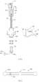
도 1은 본 발명의 하나의 실시 형태에 따른 전자담배의 실시 예를 도시한 것이다.
도 2는 본 발명의 하나의 실시 형태에 따른 전자담배에 적용될 수 있는 배선 구조의 실시 예를 도시한 것이다.1 shows an embodiment of an electronic cigarette according to one embodiment of the present invention.
2 shows an embodiment of a wiring structure that can be applied to an electronic cigarette according to one embodiment of the present invention.
아래에서 본 발명은 첨부된 도면에 제시된 실시 예를 참조하여 상세하게 설명이 되지만 실시 예는 본 발명의 명확한 이해를 위한 것으로 본 발명은 이에 제한되지 않는다. 아래의 설명에서 서로 다른 도면에서 동일한 도면 부호를 가지는 구성요소는 유사한 기능을 가지므로 발명의 이해를 위하여 필요하지 않는다면 반복하여 설명이 되지 않으며 공지의 구성요소는 간략하게 설명이 되거나 생략이 되지만 본 발명의 실시 예에서 제외되는 것으로 이해되지 않아야 한다.DETAILED DESCRIPTION OF THE PREFERRED EMBODIMENTS Hereinafter, the present invention will be described in detail with reference to the embodiments shown in the accompanying drawings, but the present invention is not limited thereto. In the following description, components having the same reference numerals in different drawings have similar functions, so that they will not be described repeatedly unless necessary for an understanding of the invention, and the known components will be briefly described or omitted. However, It should not be understood as being excluded from the embodiment of Fig.
도 1은 본 발명의 하나의 실시 형태에 따른 전자담배의 실시 예를 도시한 것이다.1 shows an embodiment of an electronic cigarette according to one embodiment of the present invention.
도 1을 참조하면, 전자담배(10)는 액상이 저장되는 저장 용기(11); 저장 용기(11)의 내부에 배치되고, 외부로부터 유입되는 공기를 유도하는 공기 관로(122), 공기 관로(122)의 한쪽 끝에 형성되고 고정 홈이 형성된 고정 유닛(121) 및 고정 홈에 고정된 기화 소자(H, F)로 이루어진 기화 유닛(12); 고정 유닛(121)의 위쪽에 결합되는 끼움 부분(151a), 끼움 부분(151a)의 위쪽에 연결되는 유도 부분(151b) 및 끼움 부분(151a)과 유도 부분(151b)의 경계를 형성하는 차단 판(151c)으로 이루어진 유도 유닛(151); 및 저장 용기(11)의 위쪽에 결합되는 마우스피스(13)를 포함하고, 상기 유도 부분(151b)은 끼움 부분(151a)에 비하여 큰 내부 직경을 가지고 그리고 차단 판(151c)은 끼움 부분(151a)에 비하여 큰 외부 직경을 가진다.Referring to FIG. 1, the
본 발명에 따른 전자담배(10)는 니코틴을 포함하거나 또는 니코틴을 포함하지 않는 용액을 전력을 이용하여 기화시켜 흡입이 가능하도록 한다. 전자담배(10)는 일반적으로 배터리 모듈(14), 마우스피스(13) 및 카트리지로 이루어질 수 있다. 배터리 모듈(14) 또는 마우스피스(13)는 카트리지에 분리 가능하도록 결합될 수 있고 카트리지는 저장 용기(11), 기화 유닛(12) 및 기화 소자(H, F)를 포함할 수 있다.The
배터리 모듈(14)의 내부에 배터리가 내장될 수 있고 그리고 앞쪽 부분에 흡연이 되는 경우 발광이 되는 엘이디를 포함할 수 있다. 다른 한편으로 인쇄 회로 기판 또는 전자 칩이 배터리 모듈(14) 또는 다른 적절한 위치에 설치될 수 있다. 전자담배의 전력 개폐는 스위치 방식이 되거나 흡입 압력 방식이 될 수 있다. 스위치 방식은 스위치(142)를 배터리 모듈(14) 또는 다른 적절한 위치에 설치하는 것을 말하고 그리고 자동 흡입 방식은 예를 들어 흡입과 동시에 외부로부터 공기가 유입되어 개폐가 되는 방식을 의미한다. 본 발명에 따른 전자담배는 이 분야에서 공지된 임의의 방식이 될 수 있고 본 발명은 제시된 실시 예에 제한되지 않는다.A battery may be embedded in the
저장 용기(11)는 내부에 용액이 저장될 수 있는 실린더 형상이 될 수 있지만 이에 제한되지 않고 다양한 형상이 될 수 있고 저장 부분(111), 마우스피스(13)가 결합되는 고정 부분(112) 및 기화 유닛(12)의 아래쪽 부분이 고정되는 결합 부분(113)으로 이루어질 수 있다.The storage container 11 may be in the shape of a cylinder in which the solution can be stored therein, but may be in various shapes without limitation, and includes a
고정 부분(112)에 결합되는 마우스피스(13)는 이 분야에 공지된 임의의 형상을 가질 수 있고 흡입 유닛(131)의 아래쪽 또는 고정 부분(112)에 끼워지는 부분에 밀폐 링(132)이 결합될 수 있다. 마우스피스(13)는 고정 부분(112)에 끼움 방식으로 결합되거나 나사 방식으로 결합이 될 수 있지만 이에 제한되지 않고 임의의 방식으로 마우스피스(13)는 고정 부분(112)에 결합이 될 수 있다.The
기화 유닛(12)은 저장 용기(11)의 아래쪽 부분으로 삽입이 되어 기화 또는 공기가 유도되는 부분이 저장 용기(11)의 내부에 배치되고 기화 유닛(12)의 아래쪽 부분은 저장 용기(11)의 마개 기능을 가지면서 이와 동시에 배터리 모듈(14)과 연결이 되는 기능을 가질 수 있다. 구체적으로 기화 유닛(12)은 튜브 형상의 공기 관로(122), 공기 관로(122)의 한쪽 끝에 형성되는 고정 유닛(121), 공기 관로(122)의 다른 쪽 끝에 형성되는 연결 부분(123), 연결 부분(123)의 아래쪽에 형성되면서 저장 용기(11)의 결합 부분(113)에 결합되는 마개 부분(124) 및 마개 부분(124)의 아래쪽에 형성되어 배터리 모듈(14)과 분리 가능하도록 체결이 되는 체결 부분(125)으로 이루어질 수 있다.The
마개 부분(124)이 결합 부분(113)의 내부에 삽입이 되는 방식으로 결합되는 것에 의하여 공기 관로(122)와 고정 유닛(121)이 저장 부분(111)의 내부에 위치하게 된다. 공기 관로(122)는 공기의 흐름이 가능한 임의의 직경을 가질 수 있고 그리고 임의의 소재로 형성될 수 있지만 바람직하게 도체 소재로 만들어질 수 있다. 공기 관로(122)가 도체로 만들어지면 기화 소자(H, F)의 한쪽 끝을 배터리 모듈(14)에 연결하는 배선 기능을 가질 수 있다.The
고정 유닛(121)은 공기 관로(122)에 비하여 큰 직경을 만들어질 수 있고 기화 소자(H, F)가 고정될 수 있는 적절한 구조를 가질 수 있다. 예를 들어 기화 소자(H, F)가 코일 형상의 니크롬선으로 이루어진 히터(H) 및 코일 형상의 내부로 관통되는 섬유 집합체(F)로 이루어질 수 있다. 이와 같은 구조를 가지는 기화 소자(H, F)를 고정시키기 위하여 고정 유닛(121)에 섬유 집합체(F)의 양 끝 부분이 고정될 수 있는 고정 홈이 형성될 수 있다. 기화 소자(H, F)는 예를 들어 세라믹 히터, 탄소 히터 또는 텅스텐 히터와 같은 이 분야에서 공지된 임의의 히터가 될 수 있다. 섬유 집합체(F)는 저장 부분(111)의 내부에 저장된 액상을 히터(H)로 전달하는 기능을 가질 수 있고 모세관 현상에 의하여 액상을 히터로 전달할 수 있다. 섬유 집합체(F)는 모세관 현상을 가지는 임의의 소재로 대체될 수 있다. 제시된 실시 예에서 섬유 집합체(F)의 양 끝 부분은 저장 부분(111)과 접촉될 수 있고 그리고 히터(H)는 고정 유닛(121))의 내부에 배치될 수 있다.The
연결 부분(123)은 공기 관로(122)의 아래쪽 부분을 마개 부분(124)과 연결하는 기능을 가지고 공기 관로(122)와 동일 또는 유사한 소재로 만들어질 수 있다. 그리고 마개 부분(124)은 결합 부분(113)의 내부로 삽입이 되면서 끝 부분은 결합 부분(113)의 바깥 반지름에 비하여 큰 형상을 가질 수 있다. 마개 부분(124)의 저장 용기(11)의 아래쪽 부분을 밀폐시키는 마개 기능을 가질 수 있고 필요에 따라 마개 부분(124)에 밀폐 링이 결합되어 용액의 누설이 방지될 수 있다.The connecting
마개 부분(124)의 아래쪽에 형성된 체결 부분(125)에 배터리 모듈(14)이 결합될 수 있다. 체결 부분(125)의 둘레 면을 따라 나사면이 형성될 수 있고 그리고 배터리 모듈(14)의 하우징(141)의 위쪽에 체결 부분(125)에 결합되는 체결 홈이 형성될 수 있다. 다른 한편으로 체결 부분(125)의 위쪽 부분에 연결 홀(126)이 형성되고 그리고 하우징(141)의 위쪽 부분에 유입 홀(143)이 형성될 수 있다. 연결 홀(126)은 공기 관로(122)와 연결이 되고 그리고 유입 홀(143)은 외부와 연결이 될 수 있다. 구체적으로 외부 공기는 유입 홀(143)을 통하여 전자담배의 내부로 유입이 되고 그리고 다시 연결 홀(126)을 통하여 공기 관로(122)로 유도될 수 있다. 공기 관로(122)로 유도된 공기는 이후 기화 소자(H, F)로 전달될 수 있다. 이후 기화 소자(H, F)에서 기화된 액상은 공기와 함께 유도 유닛(151)을 통하여 마우스피스(13)로 전달이 되어 흡입이 될 수 있다.The
본 발명에 따르면, 유도 모듈(15)은 고정 유닛(121)에 결합되는 유도 유닛(151), 유도 유닛(151)에 결합되는 차단 패킹(152) 및 저장 부분(111)의 위쪽에 결합되어 용액의 충전이 가능하도록 하는 충전 마개(153)으로 이루어질 수 있다.According to the present invention, the
유도 유닛(151)은 고정 유닛(121)의 위쪽 부분에 삽입이 되는 끼움 부분(151a), 끼움 부분(151a)의 위쪽에 연결되는 유도 부분(151b) 및 끼움 부분(151a)과 유도 부분(151b)의 경계를 형성하는 차단 판(151c)으로 이루어질 수 있다.The
끼움 부분(151a)이 고정 유닛(121)의 위쪽 부분으로부터 내부로 삽입이 되면서 기화 소자(H, F)가 고정되고 그리고 저장 부분(111)의 내부에 존재하는 액상이 기화 소자(H, F)로 유입되는 것이 방지될 수 있다. 끼움 부분(151a)은 속이 빈 원통 형상이 될 수 있고 기화 유닛(H, F)에서 발생된 기화 성분이 유도 부분(151b)을 통하여 마우스피스(13)로 유도될 수 있도록 한다. 유도 부분(151b)은 끼움 부분(151a)에 비하여 작은 직경을 가질 수 있고 바람직하게 기체가 흐를 수 있는 정도의 직경을 가질 수 있다. 이와 같이 유도 부분(151b)의 직경이 끼움 부분(151a)에 비하여 충분히 작도록 만드는 것에 의하여 기화 소자(H, F)에 존재할 수 있는 액상이 마우스피스(13)의 내부로 누설되는 것이 방지될 수 있다.The
유도 부분(151b)과 차단 판(151c)의 경계 부분에 밀폐 부재(152)가 배치될 수 있다. 마우스피스(13)의 아래쪽 부분이 밀폐 부재(152)에 접하도록 마우스피스(13)가 고정 부분(112)에 결합될 수 있다.The sealing
다양한 구조를 유도 모듈(15)이 본 발명에 따른 전자담배(10)에 적용될 수 있고 본 발명은 제시된 실시 예에 제한되지 않는다.The
본 발명에 따른 전자담배(10)는 액상의 충전이 가능한 구조를 가질 수 있다. 예를 들어 유도 모듈(15)의 위쪽 부분 또는 아래쪽 부분에 충전 마개(153)가 배치될 수 있다. 충전 마개(153)는 고정 부분(112)에 배치되거나 또는 유도 부분(151b)의 아래쪽에 배치될 수 있다. 구체적으로 고정 부분(112)에 배치되어 마우스피스(13)의 아래쪽 부분이 중앙 부분을 통과할 수 있도록 형성되거나 또는 유도 부분(151b)의 아래쪽 부분에 밀폐 부재(152)와 겹치도록 배치되거나 또는 밀폐 부재(152)와 일체로 만들어질 수 있다.The
충전 마개(153)의 실시 예에 대하여 다시 설명이 된다.The embodiment of the filling
본 발명에 따른 전자담배(10)에서 기화 소자(H, F)가 저장 용기(11)의 위쪽 부분에 위치하고 그리고 배터리 모듈(14)은 저장 용기(11)의 아래쪽에 위치한다. 그러므로 기화 소자(H, F)와 배터리 모듈(14)을 전기적으로 연결시킬 수 있는 적절한 배선 구조가 요구된다.In the
도 2의 (가)를 참조하면, 기화 소자의 히터(H)의 한쪽 끝(P1)은 고정 유닛(121)에 연결되어 공기 관로(122), 연결 부분(123) 및 체결 부분(125)을 경유하여 배터리 모듈(14)에 수용된 배터리의 한쪽 극과 전기적으로 연결이 될 수 있다. 다른 한편으로 히터(H)의 다른 끝(P2)은 공기 관로(122)의 내부에 형성된 피복 케이블(CA)에 연결될 수 있다. 그리고 피복 케이블(CA)은 공기 유입 튜브(24)를 경유하여 배터리의 다른 극에 연결이 될 수 있다.One end P1 of the heater H of the vaporizing element is connected to the fixed
고정 유닛(121)의 내부에 절연 유닛(21)이 형성되고 그리고 절연 유닛(21)의 내부에 공기 튜브(22)가 형성될 수 있다. 공기 튜브(22)는 공기 관로(122)의 위쪽 부분으로 일정한 거리만큼 분리가 되도록 아래쪽으로 연장될 수 있다. 그리고 이로 인하여 공기 튜브(22)와 공기 관로(121)의 사이에 분리 공간(V)이 형성될 수 있다.An insulating
공기 튜브(22)에 피복 케이블(CA)이 연결될 수 있고 그리고 피복 케이블(CA)은 공기 관로(122)의 내부를 통하여 연결 부분(123)의 아래쪽까지 연장될 수 있다.A sheathed cable CA can be connected to the
연결 부분(123)과 체결 부분(125)이 내부에 공기 유입 튜브(24)가 삽입될 수 있고 공기 삽입 튜브(24)는 절연 커버(23)에 의하여 연결 부분(123) 및 체결 부분(125)과 전기적으로 절연이 될 수 있다. 구체적으로 절연 커버(23)는 내부에 관로가 형성된 예를 들어 고무 또는 실리콘과 같은 절연 소재가 될 수 있고 그리고 전도체 소재로 형성된 공기 유입 튜브(24)가 관로에 삽입될 수 있다. 삽입된 공기 유입 튜브(24)의 위쪽 끝은 절연 커버(23)의 위쪽으로 돌출이 되어 피복 케이블(CA)에 연결될 수 있다. 다른 한편으로 공기 유입 튜브(24)의 다른 한쪽 끝은 배터리의 한쪽 극에 전기적으로 연결이 될 수 있다.The
히터(H)와 배터리는 다양한 방법으로 연결이 될 수 있고 본 발명은 제시된 실시 예에 제한이 되지 않는다.The heater H and the battery may be connected in various ways, and the present invention is not limited to the embodiments shown.
위에서 설명이 된 것처럼, 흡입과 동시에 외부 공기가 전자담배의 내부로 유입이 될 필요가 있다. 외부 공기의 유입을 위하여 체결 부분(125)의 위쪽 끝에 연결 홀(126)이 형성되고 그리고 배터리 모듈(14)에 유입 홀(143)이 형성될 수 있다. 다른 한편으로 공기 유입 튜브(24)의 아래쪽 끝에 유도 홈(24a)이 형성될 수 있다. 공기 유입 튜브(24)는 튜브 형상이 될 수 있고 그리고 유도 홈(24a)은 공기 유입 튜브(24)의 단면을 가로지르는 형상으로 만들어질 수 있다. 이와 같은 구조로 인하여 체결 부분(125)이 배터리 모듈의 결합 홈(144)에 체결이 되고 그리고 공기 유입 튜브(24)의 끝 부분이 결합 홈(144)에 형성된 접합 돌기(145)에 접하여도 결합 홈(144)의 내부에 있는 공기가 공기 유입 튜브(24)의 내부로 유도될 수 있도록 한다. 이와 같은 구조에서 외부 공기는 먼저 유입 홀(143)을 통하여 유입이 되고 그리고 연결 홀(126)을 통하여 결합 홈(144)의 내부로 유입될 수 있다. 이후 결합 홈(144) 내부의 공기는 유도 홈(24a)을 통하여 공기 유입 튜브(24)의 내부로 유입될 수 있다.As described above, external air needs to be introduced into the interior of the electronic cigarette at the same time as it is inhaled. A
공기 유입 튜브(24)의 한쪽 끝과 결합 돌기(145)의 결합은 배터리의 하나의 전극에 연결되도록 하는 배선 기능을 가질 수 있다.The coupling of one end of the
다양한 배선 구조가 본 발명에 따른 전자담배에 적용될 수 있고 본 발명은 제시된 실시 예에 제한되지 않는다.Various wiring structures can be applied to the electronic cigarette according to the present invention and the present invention is not limited to the embodiments shown.
도 2의 (나)를 참조하면, 충전 마개(153)은 일정한 두께를 가지는 원형 플레이트 형상이 될 수 있고 중앙 부분을 통하여 유도 유닛(151)의 유도 부분(151b)가 관통될 수 있다. 충전 마개(153)는 전체적으로 실리콘 또는 고무와 같은 신축성 소재로 만들어지거나 또는 가장자리 부분을 형성하는 스토퍼(153b)가 신축성 소재로 만들어질 수 있다. 스토퍼(153b)는 다른 부분에 대하여 두텁게 형성되거나 또는 원형의 링 형상의 될 수 있고 충전 마개(153)가 정해진 위치에 고정이 될 수 있도록 한다. 다른 한편으로 충전 마개(153)의 적절한 부분에 충전 홀(153c)가 형성될 수 있다. 충전 홀(153c)은 예를 들어 주사기 구조를 가지는 액상 충전기를 이용하여 액상이 저장 용기의 내부에 채워질 수 있도록 한다. 충전 홀(153c)은 충전이 되지 않는 경우 닫히고 그리고 충전이 되기 위하여 충전기의 바늘 부분에 의아여 개방이 되는 구조로 만들어질 수 있다. 이를 위하여 충전 마개(153)가 전체적으로 신축성 소재로 만들어지거나 또는 충전 홀(153c)이 형성된 부분이 신축성 소재로 만들어질 수 있다.2 (b), the filling
다양한 구조를 가지는 충전 마개(153)가 본 발명에 따른 전자담배에 적용이 될 수 있고 본 발명은 제시된 실시 예에 제한되지 않는다.The filling
본 발명에 따른 전자담배는 기화 유닛이 위쪽에 배치되어 기화 성분의 특성이 향상될 수 있도록 한다는 이점을 가진다. 또한 본 발명에 따른 전자담배는 액상의 충전이 용이하다는 장점을 가진다.The electronic cigarette according to the present invention has an advantage that the vaporizing unit is disposed at the upper side so that the characteristics of the vaporizing component can be improved. Further, the electronic cigarette according to the present invention has an advantage that the filling of the liquid phase is easy.
위에서 본 발명은 제시된 실시 예를 참조하여 상세하게 설명이 되었지만 이 분야에서 통상의 지식을 가진 자는 제시된 실시 예를 참조하여 본 발명의 기술적 사상을 벗어나지 않는 범위에서 다양한 변형 및 수정 발명을 만들 수 있을 것이다. 본 발명은 이와 같은 변형 및 수정 발명에 의하여 제한되지 않으며 다만 아래에 첨부된 청구범위에 의하여 제한된다.While the present invention has been particularly shown and described with reference to exemplary embodiments thereof, it will be understood by those of ordinary skill in the art that various changes in form and details may be made therein without departing from the spirit and scope of the invention . The invention is not limited by these variations and modifications, but is limited only by the claims appended hereto.
10: 전자담배 11: 저장 용기
12: 기화 유닛 13:마우스피스
14: 배터리 모듈 15: 유도 모듈
21: 절연 유닛 22: 공기 튜브
23: 절연 커버 24: 공기 유입 튜브
24a: 유도 홈
111: 저장 부분 112: 고정 부분
113: 결합 부분 121: 고정 유닛
122: 공기 관로 123: 연결 부분
124: 마개 부분 125: 체결 부분
126: 연결 홀 131: 흡입 유닛
132: 밀폐 링 141: 하우징
142: 스위치 143: 유입 홀
144: 결합 홈 145: 결합 돌기
151: 유도 유닛 151a: 끼움 부분
151b: 유도 부분 151c: 차단 판
152: 밀폐 부재 153: 충전 마개
153b: 스토퍼 153c: 충전 홀
H, F: 기화 소자 V: 분리 공간
CA: 피복 케이블10: electronic cigarette 11: storage container
12: vaporizing unit 13: mouthpiece
14: Battery module 15: Induction module
21: Insulation unit 22: Air tube
23: Insulation cover 24: Air inflow tube
24a: guide groove
111: storage part 112: fixed part
113: engaging portion 121: fixed unit
122: air duct 123: connecting portion
124: stopper part 125: fastening part
126: connection hole 131: suction unit
132: sealing ring 141: housing
142: switch 143: inlet hole
144: engaging groove 145: engaging projection
151:
151b: guiding
152: sealing member 153: filling plug
153b:
H, F: Vaporization element V: separation space
CA: Cloth cable
Claims (3)
Translated fromKorean액상이 저장되는 저장 용기(11);
저장 용기(11)의 내부에 배치되고, 외부로부터 유입되는 공기를 유도하는 공기 관로(122), 공기 관로(122)의 한쪽 끝에 형성되고 고정 홈이 형성된 고정 유닛(121) 및 고정 홈에 고정된 기화 소자(H, F)로 이루어진 기화 유닛(12);
고정 유닛(121)의 위쪽에 결합되는 끼움 부분(151a), 끼움 부분(151a)의 위쪽에 연결되는 유도 부분(151b) 및 끼움 부분(151a)과 유도 부분(151b)의 경계를 형성하는 차단 판(151c)으로 이루어진 유도 유닛(151); 및
저장 용기(11)의 위쪽에 결합되는 마우스피스(13)를 포함하고,
상기 유도 부분(151b)은 기화 소자(H, F)에 존재하는 액상이 마우스피스(13)의 내부로 누설되는 것을 방지하도록 끼움 부분(151a)에 비하여 작은 직경을 가지고, 차단 판(151c)은 끼움 부분(151a)에 비하여 큰 외부 직경을 가지는 것을 특징으로 하는 전자담배.In electronic cigarettes,
A storage container (11) in which a liquid phase is stored;
An air duct 122 which is disposed inside the storage container 11 and guides air introduced from the outside, a fixed unit 121 formed at one end of the air duct 122 and formed with a fixing groove, A vaporizing unit 12 composed of vaporizing elements H and F;
An insertion portion 151a coupled to the upper portion of the fixed unit 121, an induction portion 151b connected to the upper portion of the fitting portion 151a and a shielding plate 151b forming the boundary between the fitting portion 151a and the guiding portion 151b. A guide unit 151 composed of a guide member 151c; And
And a mouthpiece (13) coupled to the upper side of the storage container (11)
The guiding portion 151b has a smaller diameter than the fitting portion 151a to prevent the liquid phase present in the vaporizing elements H and F from leaking into the mouthpiece 13, Has a larger outer diameter than the fitting portion (151a).
Priority Applications (1)
| Application Number | Priority Date | Filing Date | Title |
|---|---|---|---|
| KR1020130109607AKR101516304B1 (en) | 2013-09-12 | 2013-09-12 | Electrical Cigarette |
Applications Claiming Priority (1)
| Application Number | Priority Date | Filing Date | Title |
|---|---|---|---|
| KR1020130109607AKR101516304B1 (en) | 2013-09-12 | 2013-09-12 | Electrical Cigarette |
Publications (2)
| Publication Number | Publication Date |
|---|---|
| KR20150030409A KR20150030409A (en) | 2015-03-20 |
| KR101516304B1true KR101516304B1 (en) | 2015-05-04 |
Family
ID=53024457
Family Applications (1)
| Application Number | Title | Priority Date | Filing Date |
|---|---|---|---|
| KR1020130109607AExpired - Fee RelatedKR101516304B1 (en) | 2013-09-12 | 2013-09-12 | Electrical Cigarette |
Country Status (1)
| Country | Link |
|---|---|
| KR (1) | KR101516304B1 (en) |
Cited By (17)
| Publication number | Priority date | Publication date | Assignee | Title |
|---|---|---|---|---|
| KR20180038630A (en) | 2016-10-07 | 2018-04-17 | 석인선 | Electronic cigarette with liquid inlet using a magnetic force |
| KR20180042895A (en) | 2016-10-19 | 2018-04-27 | 석인선 | The assemble structure of joiner for electronic cigarette |
| WO2019050131A1 (en)* | 2017-09-06 | 2019-03-14 | 주식회사 케이티앤지 | Aerosol generation device |
| KR102065072B1 (en) | 2016-12-16 | 2020-01-10 | 주식회사 케이티앤지 | Apparatus for generating aerosols |
| JP2020527040A (en)* | 2017-09-06 | 2020-09-03 | ケーティー・アンド・ジー・コーポレーション | Aerosol generator |
| US11197497B2 (en) | 2017-04-11 | 2021-12-14 | Kt&G Corporation | Aerosol generating device |
| US11246341B2 (en) | 2016-12-16 | 2022-02-15 | Kt&G Corporation | Aerosol generation method and apparatus |
| US11246345B2 (en) | 2017-04-11 | 2022-02-15 | Kt&G Corporation | Aerosol generating device provided with rotary heater |
| US11252999B2 (en) | 2017-04-11 | 2022-02-22 | Kt&G Corporation | Aerosol generating device |
| US11432593B2 (en) | 2017-04-11 | 2022-09-06 | Kt&G Corporation | Device for cleaning smoking member, and smoking member system |
| US11470882B2 (en) | 2017-04-11 | 2022-10-18 | Kt&G Corporation | Device for holding smoking member, and smoking member system |
| US11622582B2 (en) | 2017-04-11 | 2023-04-11 | Kt&G Corporation | Aerosol generating device and method for providing adaptive feedback through puff recognition |
| US11641879B2 (en) | 2017-08-09 | 2023-05-09 | Kt&G Corporation | Aerosol generation device and control method for aerosol generation device |
| US11771138B2 (en) | 2017-04-11 | 2023-10-03 | Kt&G Corporation | Aerosol generating device and method for providing smoking restriction function in aerosol generating device |
| US11805815B2 (en) | 2017-05-26 | 2023-11-07 | Kt&G Corporation | Heater assembly and aerosol generation device comprising same |
| US11849762B2 (en) | 2017-08-09 | 2023-12-26 | Kt&G Corporation | Electronic cigarette control method and device |
| US12274294B2 (en) | 2017-03-30 | 2025-04-15 | Kt&G Corporation | Aerosol generating apparatus and cradle capable of receiving same |
Families Citing this family (3)
| Publication number | Priority date | Publication date | Assignee | Title |
|---|---|---|---|---|
| KR102615430B1 (en)* | 2015-09-16 | 2023-12-19 | 필립모리스 프로덕츠 에스.에이. | Electronic cigarette with visible liquid container |
| EP3376885B1 (en)* | 2015-11-17 | 2019-08-28 | Philip Morris Products S.a.s. | Cartridge for an aerosol-generating system with identification inductor |
| CN108936812B (en)* | 2017-05-27 | 2021-09-24 | 深圳市赛尔美电子科技有限公司 | Heating non-combustion smoking set and control method thereof |
Citations (3)
| Publication number | Priority date | Publication date | Assignee | Title |
|---|---|---|---|---|
| KR101183157B1 (en) | 2012-01-18 | 2012-09-14 | 주식회사 시그닛코리아 | Electronic cigarette |
| KR101184758B1 (en) | 2012-01-13 | 2012-09-19 | 이영인 | Cartridge of electric cigarette for preventing leakage |
| KR101364016B1 (en) | 2012-10-08 | 2014-02-17 | 김한기 | Cartridge for electric cigarette capable of exchanging heat assembly |
- 2013
- 2013-09-12KRKR1020130109607Apatent/KR101516304B1/ennot_activeExpired - Fee Related
Patent Citations (3)
| Publication number | Priority date | Publication date | Assignee | Title |
|---|---|---|---|---|
| KR101184758B1 (en) | 2012-01-13 | 2012-09-19 | 이영인 | Cartridge of electric cigarette for preventing leakage |
| KR101183157B1 (en) | 2012-01-18 | 2012-09-14 | 주식회사 시그닛코리아 | Electronic cigarette |
| KR101364016B1 (en) | 2012-10-08 | 2014-02-17 | 김한기 | Cartridge for electric cigarette capable of exchanging heat assembly |
Cited By (33)
| Publication number | Priority date | Publication date | Assignee | Title |
|---|---|---|---|---|
| KR20180038630A (en) | 2016-10-07 | 2018-04-17 | 석인선 | Electronic cigarette with liquid inlet using a magnetic force |
| KR20180042895A (en) | 2016-10-19 | 2018-04-27 | 석인선 | The assemble structure of joiner for electronic cigarette |
| US11457661B2 (en) | 2016-12-16 | 2022-10-04 | Kt&G Corporation | Aerosol generation method and apparatus |
| KR102065072B1 (en) | 2016-12-16 | 2020-01-10 | 주식회사 케이티앤지 | Apparatus for generating aerosols |
| US12029238B2 (en) | 2016-12-16 | 2024-07-09 | Kt&G Corporation | Aerosol generation method and apparatus |
| US11882870B2 (en) | 2016-12-16 | 2024-01-30 | Kt&G Corporation | Aerosol generation method and apparatus |
| US11246341B2 (en) | 2016-12-16 | 2022-02-15 | Kt&G Corporation | Aerosol generation method and apparatus |
| US11871781B2 (en) | 2016-12-16 | 2024-01-16 | Kt&G Corporation | Aerosol generation method and apparatus |
| US11252993B2 (en) | 2016-12-16 | 2022-02-22 | Kt&G Corporation | Aerosol generation method and apparatus |
| US11627759B2 (en) | 2016-12-16 | 2023-04-18 | Kt&G Corporation | Aerosol generation method and apparatus |
| US12274294B2 (en) | 2017-03-30 | 2025-04-15 | Kt&G Corporation | Aerosol generating apparatus and cradle capable of receiving same |
| US11470882B2 (en) | 2017-04-11 | 2022-10-18 | Kt&G Corporation | Device for holding smoking member, and smoking member system |
| US11771138B2 (en) | 2017-04-11 | 2023-10-03 | Kt&G Corporation | Aerosol generating device and method for providing smoking restriction function in aerosol generating device |
| US12295420B2 (en) | 2017-04-11 | 2025-05-13 | Kt&G Corporation | Aerosol generation system of preheating heater |
| US11432593B2 (en) | 2017-04-11 | 2022-09-06 | Kt&G Corporation | Device for cleaning smoking member, and smoking member system |
| US11259571B2 (en) | 2017-04-11 | 2022-03-01 | Kt&G Corporation | Aerosol generating apparatus provided with movable heater |
| US12102131B2 (en) | 2017-04-11 | 2024-10-01 | Kt&G Corporation | Aerosol generating device and method for providing adaptive feedback through puff recognition |
| US11622582B2 (en) | 2017-04-11 | 2023-04-11 | Kt&G Corporation | Aerosol generating device and method for providing adaptive feedback through puff recognition |
| US11252999B2 (en) | 2017-04-11 | 2022-02-22 | Kt&G Corporation | Aerosol generating device |
| US11197497B2 (en) | 2017-04-11 | 2021-12-14 | Kt&G Corporation | Aerosol generating device |
| US11246345B2 (en) | 2017-04-11 | 2022-02-15 | Kt&G Corporation | Aerosol generating device provided with rotary heater |
| US11805815B2 (en) | 2017-05-26 | 2023-11-07 | Kt&G Corporation | Heater assembly and aerosol generation device comprising same |
| US11849762B2 (en) | 2017-08-09 | 2023-12-26 | Kt&G Corporation | Electronic cigarette control method and device |
| US11641879B2 (en) | 2017-08-09 | 2023-05-09 | Kt&G Corporation | Aerosol generation device and control method for aerosol generation device |
| JP7323657B2 (en) | 2017-09-06 | 2023-08-08 | ケーティー アンド ジー コーポレイション | aerosol generator |
| JP2022050559A (en)* | 2017-09-06 | 2022-03-30 | ケーティー アンド ジー コーポレイション | Aerosol generator |
| US11647785B2 (en) | 2017-09-06 | 2023-05-16 | Kt&G Corporation | Aerosol generation device having structure for preventing liquid leakage |
| US11937631B2 (en) | 2017-09-06 | 2024-03-26 | Kt&G Corporation | Aerosol generation device having concealed fastening portion |
| JP2020527040A (en)* | 2017-09-06 | 2020-09-03 | ケーティー・アンド・ジー・コーポレーション | Aerosol generator |
| US12063961B2 (en) | 2017-09-06 | 2024-08-20 | Kt&G Corporation | Aerosol generation device |
| US11259567B2 (en) | 2017-09-06 | 2022-03-01 | Kt&G Corporation | Aerosol generation device |
| WO2019050131A1 (en)* | 2017-09-06 | 2019-03-14 | 주식회사 케이티앤지 | Aerosol generation device |
| US11344062B2 (en) | 2017-09-06 | 2022-05-31 | Kt&G Corporation | Aerosol generation device having concealed fastening portion |
Also Published As
| Publication number | Publication date |
|---|---|
| KR20150030409A (en) | 2015-03-20 |
Similar Documents
| Publication | Publication Date | Title |
|---|---|---|
| KR101516304B1 (en) | Electrical Cigarette | |
| US11872341B2 (en) | Vapor provision cartridge and system | |
| KR101184758B1 (en) | Cartridge of electric cigarette for preventing leakage | |
| ES2902232T3 (en) | Aerosol distribution device | |
| RU2704940C2 (en) | Configuration of power supply section for electronic device for hover and electronic device for hovering | |
| EP3123878B1 (en) | Electronic cigarette | |
| KR101623429B1 (en) | Cartridge for Inhaling Apparatus with Electrical Power | |
| CN106455697B (en) | e-cigarette | |
| KR101241782B1 (en) | Structure for Supplying Outer Air in Electric Cigarette | |
| CN104039182B (en) | Electronic cigarette and its soup stick | |
| MY154105A (en) | An electronic vaporisation cigarette | |
| KR20130084789A (en) | Electronic cigarette | |
| WO2018113528A1 (en) | Cigarette cartridge, atomizing assembly and electronic cigarette | |
| KR20130031550A (en) | Cartridge with separated volume for electric cigarette | |
| KR101516309B1 (en) | Exchangeable Type of Cartridge for Electric Cigarette | |
| KR101364772B1 (en) | Cartridge for Electronic Cigarette | |
| KR20130027909A (en) | Cartridge for electronic cigarette with enhanced inhaling flavor | |
| WO2015088290A2 (en) | Atomization device | |
| KR20160080550A (en) | Cartridge for Electronic Cigarette | |
| KR101436392B1 (en) | Apparatus for Inhaling Gas Evaporated with Electrical Power | |
| KR20160130342A (en) | Atomizing device for an electronic Cigarette | |
| KR101245578B1 (en) | Structure for Supplying Nicotine Solution in Electric Cigarette | |
| KR101245581B1 (en) | Structure for Evaporating Nicotine Solution in Electric Cigarette | |
| KR101516302B1 (en) | Apparatus for Inhaling Gas Evaporated with Electrical Power in a Single Body with Battery | |
| KR101241785B1 (en) | Structure For Vaporizing Nicotine Solution in Electronic Cigarette |
Legal Events
| Date | Code | Title | Description |
|---|---|---|---|
| A201 | Request for examination | ||
| PA0109 | Patent application | St.27 status event code:A-0-1-A10-A12-nap-PA0109 | |
| PA0201 | Request for examination | St.27 status event code:A-1-2-D10-D11-exm-PA0201 | |
| D13-X000 | Search requested | St.27 status event code:A-1-2-D10-D13-srh-X000 | |
| D14-X000 | Search report completed | St.27 status event code:A-1-2-D10-D14-srh-X000 | |
| E902 | Notification of reason for refusal | ||
| PE0902 | Notice of grounds for rejection | St.27 status event code:A-1-2-D10-D21-exm-PE0902 | |
| P11-X000 | Amendment of application requested | St.27 status event code:A-2-2-P10-P11-nap-X000 | |
| P13-X000 | Application amended | St.27 status event code:A-2-2-P10-P13-nap-X000 | |
| PG1501 | Laying open of application | St.27 status event code:A-1-1-Q10-Q12-nap-PG1501 | |
| E701 | Decision to grant or registration of patent right | ||
| PE0701 | Decision of registration | St.27 status event code:A-1-2-D10-D22-exm-PE0701 | |
| N231 | Notification of change of applicant | ||
| PN2301 | Change of applicant | St.27 status event code:A-3-3-R10-R13-asn-PN2301 St.27 status event code:A-3-3-R10-R11-asn-PN2301 | |
| GRNT | Written decision to grant | ||
| PR0701 | Registration of establishment | St.27 status event code:A-2-4-F10-F11-exm-PR0701 | |
| PR1002 | Payment of registration fee | St.27 status event code:A-2-2-U10-U11-oth-PR1002 Fee payment year number:1 | |
| PG1601 | Publication of registration | St.27 status event code:A-4-4-Q10-Q13-nap-PG1601 | |
| P22-X000 | Classification modified | St.27 status event code:A-4-4-P10-P22-nap-X000 | |
| LAPS | Lapse due to unpaid annual fee | ||
| PC1903 | Unpaid annual fee | St.27 status event code:A-4-4-U10-U13-oth-PC1903 Not in force date:20180424 Payment event data comment text:Termination Category : DEFAULT_OF_REGISTRATION_FEE | |
| PC1903 | Unpaid annual fee | St.27 status event code:N-4-6-H10-H13-oth-PC1903 Ip right cessation event data comment text:Termination Category : DEFAULT_OF_REGISTRATION_FEE Not in force date:20180424 | |
| R18-X000 | Changes to party contact information recorded | St.27 status event code:A-5-5-R10-R18-oth-X000 | |
| R18-X000 | Changes to party contact information recorded | St.27 status event code:A-5-5-R10-R18-oth-X000 | |
| R18-X000 | Changes to party contact information recorded | St.27 status event code:A-5-5-R10-R18-oth-X000 | |
| P22-X000 | Classification modified | St.27 status event code:A-4-4-P10-P22-nap-X000 | |
| R18-X000 | Changes to party contact information recorded | St.27 status event code:A-5-5-R10-R18-oth-X000 | |
| R18-X000 | Changes to party contact information recorded | St.27 status event code:A-5-5-R10-R18-oth-X000 |