KR101515951B1 - Apparatus for exercising of finger - Google Patents
Apparatus for exercising of fingerDownload PDFInfo
- Publication number
- KR101515951B1 KR101515951B1KR1020130148211AKR20130148211AKR101515951B1KR 101515951 B1KR101515951 B1KR 101515951B1KR 1020130148211 AKR1020130148211 AKR 1020130148211AKR 20130148211 AKR20130148211 AKR 20130148211AKR 101515951 B1KR101515951 B1KR 101515951B1
- Authority
- KR
- South Korea
- Prior art keywords
- module
- housing
- extension
- bending
- finger
- Prior art date
- Legal status (The legal status is an assumption and is not a legal conclusion. Google has not performed a legal analysis and makes no representation as to the accuracy of the status listed.)
- Expired - Fee Related
Links
Images


Classifications
- A—HUMAN NECESSITIES
- A61—MEDICAL OR VETERINARY SCIENCE; HYGIENE
- A61H—PHYSICAL THERAPY APPARATUS, e.g. DEVICES FOR LOCATING OR STIMULATING REFLEX POINTS IN THE BODY; ARTIFICIAL RESPIRATION; MASSAGE; BATHING DEVICES FOR SPECIAL THERAPEUTIC OR HYGIENIC PURPOSES OR SPECIFIC PARTS OF THE BODY
- A61H1/00—Apparatus for passive exercising; Vibrating apparatus; Chiropractic devices, e.g. body impacting devices, external devices for briefly extending or aligning unbroken bones
- A61H1/02—Stretching or bending or torsioning apparatus for exercising
- A61H1/0274—Stretching or bending or torsioning apparatus for exercising for the upper limbs
- A61H1/0285—Hand
- A61H1/0288—Fingers
- A—HUMAN NECESSITIES
- A61—MEDICAL OR VETERINARY SCIENCE; HYGIENE
- A61H—PHYSICAL THERAPY APPARATUS, e.g. DEVICES FOR LOCATING OR STIMULATING REFLEX POINTS IN THE BODY; ARTIFICIAL RESPIRATION; MASSAGE; BATHING DEVICES FOR SPECIAL THERAPEUTIC OR HYGIENIC PURPOSES OR SPECIFIC PARTS OF THE BODY
- A61H2201/00—Characteristics of apparatus not provided for in the preceding codes
- A61H2201/01—Constructive details
- A61H2201/0119—Support for the device
- A—HUMAN NECESSITIES
- A61—MEDICAL OR VETERINARY SCIENCE; HYGIENE
- A61H—PHYSICAL THERAPY APPARATUS, e.g. DEVICES FOR LOCATING OR STIMULATING REFLEX POINTS IN THE BODY; ARTIFICIAL RESPIRATION; MASSAGE; BATHING DEVICES FOR SPECIAL THERAPEUTIC OR HYGIENIC PURPOSES OR SPECIFIC PARTS OF THE BODY
- A61H2201/00—Characteristics of apparatus not provided for in the preceding codes
- A61H2201/01—Constructive details
- A61H2201/0192—Specific means for adjusting dimensions
- A—HUMAN NECESSITIES
- A61—MEDICAL OR VETERINARY SCIENCE; HYGIENE
- A61H—PHYSICAL THERAPY APPARATUS, e.g. DEVICES FOR LOCATING OR STIMULATING REFLEX POINTS IN THE BODY; ARTIFICIAL RESPIRATION; MASSAGE; BATHING DEVICES FOR SPECIAL THERAPEUTIC OR HYGIENIC PURPOSES OR SPECIFIC PARTS OF THE BODY
- A61H2201/00—Characteristics of apparatus not provided for in the preceding codes
- A61H2201/16—Physical interface with patient
- A61H2201/1602—Physical interface with patient kind of interface, e.g. head rest, knee support or lumbar support
- A61H2201/1635—Hand or arm, e.g. handle
- A61H2201/1638—Holding means therefor
- A—HUMAN NECESSITIES
- A61—MEDICAL OR VETERINARY SCIENCE; HYGIENE
- A61H—PHYSICAL THERAPY APPARATUS, e.g. DEVICES FOR LOCATING OR STIMULATING REFLEX POINTS IN THE BODY; ARTIFICIAL RESPIRATION; MASSAGE; BATHING DEVICES FOR SPECIAL THERAPEUTIC OR HYGIENIC PURPOSES OR SPECIFIC PARTS OF THE BODY
- A61H2201/00—Characteristics of apparatus not provided for in the preceding codes
- A61H2201/16—Physical interface with patient
- A61H2201/1602—Physical interface with patient kind of interface, e.g. head rest, knee support or lumbar support
- A61H2201/165—Wearable interfaces
- A—HUMAN NECESSITIES
- A61—MEDICAL OR VETERINARY SCIENCE; HYGIENE
- A61H—PHYSICAL THERAPY APPARATUS, e.g. DEVICES FOR LOCATING OR STIMULATING REFLEX POINTS IN THE BODY; ARTIFICIAL RESPIRATION; MASSAGE; BATHING DEVICES FOR SPECIAL THERAPEUTIC OR HYGIENIC PURPOSES OR SPECIFIC PARTS OF THE BODY
- A61H2201/00—Characteristics of apparatus not provided for in the preceding codes
- A61H2201/50—Control means thereof
- A61H2201/5058—Sensors or detectors
- A61H2201/5071—Pressure sensors
- A—HUMAN NECESSITIES
- A61—MEDICAL OR VETERINARY SCIENCE; HYGIENE
- A61H—PHYSICAL THERAPY APPARATUS, e.g. DEVICES FOR LOCATING OR STIMULATING REFLEX POINTS IN THE BODY; ARTIFICIAL RESPIRATION; MASSAGE; BATHING DEVICES FOR SPECIAL THERAPEUTIC OR HYGIENIC PURPOSES OR SPECIFIC PARTS OF THE BODY
- A61H2205/00—Devices for specific parts of the body
- A61H2205/06—Arms
- A61H2205/065—Hands
- A61H2205/067—Fingers
Landscapes
- Health & Medical Sciences (AREA)
- Epidemiology (AREA)
- Pain & Pain Management (AREA)
- Physical Education & Sports Medicine (AREA)
- Rehabilitation Therapy (AREA)
- Life Sciences & Earth Sciences (AREA)
- Animal Behavior & Ethology (AREA)
- General Health & Medical Sciences (AREA)
- Public Health (AREA)
- Veterinary Medicine (AREA)
- Rehabilitation Tools (AREA)
Abstract
Translated fromKoreanDescription
Translated fromKorean본 발명은 손가락 운동 장치에 관한 것으로서, 보다 상세하게는 사용자의 착용이 용이하고, 손가락 관절의 굴곡량을 정밀하게 조절할 수 있는 손가락 운동 장치에 관한 것이다.
The present invention relates to a finger exercising apparatus, and more particularly, to a finger exercising apparatus which can be easily worn by a user and can precisely control a bending amount of a finger joint.
일반적으로 질병 또는 사고에 의해 손의 운동 기능이 저하된 사용자는 사용자의 손 관절부를 굴곡 및 신전시키는 재활운동에 의해 손의 기능을 유지하거나 또는 회복시키게 된다. 이를 위해, 사용자는 물리치료사의 보조를 받아 재활운동하거나 또는 상지운동기구를 사용하여 재활운동한다.In general, a user whose hand movement function has been deteriorated due to a disease or an accident causes the hand function to be maintained or restored by a rehabilitation exercise in which the user's hand joint is flexed and stretched. To this end, the user may rehabilitate with the assistance of a physical therapist or rehabilitate using the upper extremity exercise apparatus.
일반적으로, 사용자의 손가락 관절을 굴곡 및 신전시키는 재활운동에 사용되는 상지운동기구는 부피가 크고 무거워 일정 장소에 설치하여 사용하는 로봇형 상지운동기구 또는 스프링이나 고무밴드가 구비된 장갑형 상지운동기구가 있다.Generally, the upper extremity exercise apparatus used for the rehabilitation exercise for flexing and extending the user's finger joint is bulky and heavy, and a robot-type upper extremity exercise apparatus used in a certain place, or an arm type upper extremity exercise apparatus having a spring or rubber band have.
로봇형 상지운동기구는 일정 장소에 설치되면, 이후 이동이 어렵고, 이에 사용자의 접근성이 떨어지는 문제가 있다. 장갑형 상지운동기구는 사용자가 직접 손가락을 움직여 재활운동을 하도록 형성되어 손 기능이 저하된 사용자가 사용하기에 효용성을 저하된다. 즉, 장갑형 상지운동기구는 장갑에 탄성밴드를 장착하여 탄성력에 의해 사용자가 능동운동을 하며, 탄성밴드의 탄성력을 사용자가 감당하여야 함에, 그 효용성이 떨어진다. 또한, 그 구성에 의하여 움직임이 단조로워서 효과적인 관절 운동에 어려움이 있다.When the robot-type upper limb exerciser is installed in a certain place, it is difficult to move the robot since then, and the accessibility of the user is deteriorated. The glove type upper limb exercising device is configured to perform a rehabilitation exercise by moving the finger of the user directly, which is deteriorated in utility for a user whose hand function is deteriorated. That is, the glove-type upper extremity exercise apparatus is equipped with an elastic band in the glove, the user performs active motion by the elastic force, and the elasticity of the elastic band is required to be supported by the user. In addition, the movement is monotonous due to its configuration, which makes it difficult to effectively exercise the joint.
이에, 휴대 및 착용이 용이하고, 사용자의 손가락 관절의 회복을 빠르게 진행시키도록 손가락 관절을 정밀하게 조절하며, 손 기능이 저하된 사용자가 사용하기 용이하도록 외부 동력에 의해 손가락 관절을 굴곡 및 신전시킬 수 있는 상지운동기구가 요구되고 있다.
Therefore, it is possible to precisely adjust the finger joint so that the user can easily carry and wear the finger joint, to quickly recover the user's finger joint, and to flex and extend the finger joint by external power The upper extremity exercise apparatus which can be used is required.
본 발명은 사용자의 손가락 관절의 회복속도를 빠르게 진행시키도록 사용자 손가락 관절의 굴곡량을 정밀하게 조절할 수 있는 손가락 운동 장치를 제공한다.The present invention provides a finger exercise device capable of precisely adjusting a bending amount of a user's finger joint so as to speed up the recovery speed of the user's finger joint.
본 발명은 손의 운동기능이 저하된 사용자의 착용이 용이한 손가락 운동 장치를 제공한다.The present invention provides a finger exercise apparatus in which a wearer can easily wear his or her hand with a reduced movement function of the hand.
본 발명은 손의 운동기능이 저하된 사용자의 사용이 용이하도록 동력에 의해 손가락 관절을 굴곡 및 신전시킬 수 있는 손가락 운동 장치를 제공한다.
The present invention provides a finger exercising apparatus capable of bending and extending a finger joint by a power so as to facilitate use of a user whose hand motion function is degraded.
본 발명의 실시 형태에 따른 손가락 운동 장치는 사용자의 손이 착용되는 착용 모듈; 상기 착용 모듈의 일측에 배치되는 굴곡 모듈; 상기 일측에 대향되는 상기 착용 모듈의 타측에 배치되는 신전 모듈; 각각의 일단이 상기 착용 모듈의 손가락 마디부들의 단부에 각각 연결되고, 각각의 타단이 상기 굴곡 모듈에 연결되는 복수개의 굴곡 와이어; 및 각각의 일단이 상기 착용 모듈의 손가락 마디부들의 복수의 위치에 각각 연결되고, 각각의 타단이 상기 신전 모듈에 연결되는 복수개의 신전 와이어; 를 포함할 수 있다.A finger exercise device according to an embodiment of the present invention includes a wear module in which a user's hand is worn; A bending module disposed on one side of the wear module; An extension module disposed on the other side of the wear module facing the one side; A plurality of bending wires each having one end connected to an end of the finger portion of the wear module, respectively, and the other end connected to the bending module; And a plurality of extension wires each having one end connected to a plurality of positions of the finger nodule portions of the wear module and each of the other ends connected to the extension module; . ≪ / RTI >
상기 굴곡 와이어들은 상기 굴곡 모듈의 굴곡 조절부에 연결되고, 상기 굴곡 조절부의 회전에 따라 상기 손가락 마디부들을 동시에 굴곡 또는 신전시키고, 상기 신전 와이어들은 상기 신전 모듈의 신전 조절부들에 각각 연결되고, 상기 신전 조절부들의 회전에 따라 상기 손가락 마디부들의 굴곡량을 각각 조절할 수 있다.Wherein the flexion wires are connected to the flexion control portion of the flexion module, and the finger portions are flexed or extended at the same time as the rotation of the flexion control portion, the extension wires are respectively connected to the extension control portions of the extension module, The amount of bending of the finger joints can be adjusted according to the rotation of the extension adjusting portions.
상기 착용 모듈은, 상기 굴곡 모듈과 신전 모듈의 사이에 배치되는 손허리부; 상기 손허리부에 회전 가능하게 연결되고, 손가락을 각각 감싸도록 형성되는 복수개의 상기 손가락 마디부; 및 상기 손가락 마디부들의 각각의 단부에 형성되는 복수개의 손가락 전단부; 를 포함할 수 있고, 상기 손가락 마디부는 손가락의 첫 마디를 감싸는 제1 마디부, 손가락의 중간 마디를 감싸는 제2 마디부, 손가락의 끝 마디를 감싸는 제3 마디부를 포함할 수 있다.Wherein the wear module comprises: a hand waist portion disposed between the bending module and the extension module; A plurality of finger nail portions rotatably connected to the back of the hand and formed to surround the fingers, respectively; And a plurality of finger front ends formed at respective ends of the finger segments; The finger nodule may include a first nodal portion surrounding the first node of the finger, a second nodal portion surrounding the middle node of the finger, and a third nodal portion surrounding the end node of the finger.
상기 신전 와이어들의 각각의 일단은 상기 제1 마디부들과 제2 마디부들과 제3 마디부들에 각각 연결될 수 있다.One end of each of the extension wires may be connected to the first, second, and third nodal portions, respectively.
상기 굴곡 모듈은, 상기 착용 모듈의 길이방향에 교차하는 방향으로 연장 형성되고, 내부공간을 가지는 제1 하우징; 상하방향으로 연장 형성되고, 상기 제1 하우징의 길이방향의 양 단부 중 어느 한 단부에 장착되는 제1 하우징 지지부; 상기 제1 하우징의 길이방향으로 연장 형성되고, 상기 제1 하우징의 길이방향으로 상기 제1 하우징과 제1 하우징 지지부를 관통하여 장착되는 상기 굴곡 조절부; 및 상기 제1 하우징의 반대측에서 상기 제1 하우징 지지부에 착탈 가능하게 장착되고, 상기 굴곡 조절부에 연결되는 제1 구동부; 를 포함할 수 있다.The bending module includes: a first housing extending in a direction crossing the longitudinal direction of the wear module, the first housing having an inner space; A first housing supporting part extending in the vertical direction and mounted at either end of both ends in the longitudinal direction of the first housing; The bending controller being extended in the longitudinal direction of the first housing and mounted through the first housing and the first housing support in a longitudinal direction of the first housing; And a first driving part detachably mounted on the first housing supporting part on the opposite side of the first housing and connected to the bending control part; . ≪ / RTI >
상기 신전 모듈은, 상기 착용 모듈의 길이방향에 교차하는 방향으로 연장 형성되고, 내부공간을 가지는 제2 하우징; 상하방향으로 연장 형성되고, 상기 제1 하우징 지지부에 가까운 상기 제2 하우징의 단부에 장착되는 제2 하우징 지지부; 상기 제2 하우징의 길이방향으로 연장 형성되고, 상기 제2 하우징의 길이방향으로 상기 제2 하우징과 상기 제2 하우징 지지부를 관통하여 장착되는 복수개의 상기 신전 조절부; 상기 제2 하우징의 반대측에서 상기 제2 하우징 지지부에 착탈 가능하게 장착되고, 상기 신전 조절부에 연결되는 제2 구동부; 를 포함할 수 있다.Wherein the extension module comprises: a second housing extending in a direction crossing the longitudinal direction of the wear module, the second housing having an inner space; A second housing supporting part extending in the vertical direction and mounted on an end of the second housing close to the first housing supporting part; A plurality of extension adjusters extending in the longitudinal direction of the second housing and mounted through the second housing and the second housing support in a longitudinal direction of the second housing; A second driving part detachably mounted on the second housing supporting part on the opposite side of the second housing and connected to the extension adjusting part; . ≪ / RTI >
상기 신전 조절부는, 상기 신전 와이어들 중 일단이 상기 제1 마디부들에 연결된 신전 와이어들의 타단과 연결되는 중수지절관절 조절부; 상기 신전 와이어들 중 일단이 상기 제2 마디부들에 연결된 신전 와이어들의 타단과 연결되는 근위지절관절 조절부; 상기 신전 와이어들 중 일단이 상기 제3 마디부들에 연결된 신전 와이어들의 타단과 연결되는 원위지절관절 조절부; 를 포함할 수 있다.Wherein the extension adjusting unit comprises: a heavy knuckle joint adjusting part having one end of the extension wires connected to the other end of extension wires connected to the first knobs; A proximal femoral joint regulator having one end of the extension wires connected to the other end of the extension wires connected to the second distal end; A distal joint joint adjuster having one end of the extension wires connected to the other end of the extension wires connected to the third joints; . ≪ / RTI >
상기 굴곡 조절부는, 상기 제1 하우징의 길이방향으로 연장 형성되고, 길이방향으로 형성되는 중공과 상기 중공과 연결되어 상기 굴곡 와이어가 삽입되는 복수개의 개구를 구비하는 제1 축 부재; 상기 제1 하우징 지지부에 가까운 상기 제1 축 부재의 단부에 형성되고, 상기 제1 구동부와 연결되는 제1 소켓; 및 상기 제1 하우징의 외측에 위치하며, 상기 제1 축 부재의 나머지 단부에 형성되는 상기 중공의 단부를 개폐시키도록 상기 제1 축 부재의 나머지 단부에 장착되는 제1 압착 부재; 를 포함할 수 있다.The bending control unit includes a first shaft member extending in the longitudinal direction of the first housing and having a hollow formed in a longitudinal direction and a plurality of openings connected to the hollow to insert the bent wire; A first socket formed at an end of the first shaft member close to the first housing support and connected to the first driving unit; And a first pressing member located on the outer side of the first housing and mounted on the other end of the first shaft member to open and close the hollow end formed at the other end of the first shaft member; . ≪ / RTI >
상기 신전 조절부는, 상기 제2 하우징의 길이방향으로 연장 형성되고, 길이방향으로 형성되는 중공과 상기 중공과 연결되어 상기 신전 와이어가 삽입되는 복수개의 개구를 구비하는 제2 축 부재; 상기 제2 하우징 지지부에 가까운 상기 제2 축 부재의 단부에 형성되고, 상기 제2 구동부와 연결되는 제2 소켓; 및 상기 제2 하우징의 외측에 위치하며, 상기 제2 축 부재의 나머지 단부에 형성되는 상기 중공의 단부를 개폐시키도록 상기 제2 축 부재의 나머지 단부에 장착되는 제2 압착 부재; 를 포함할 수 있다.A second shaft member extending in a longitudinal direction of the second housing and having a hollow formed in a longitudinal direction and a plurality of openings connected to the hollow and inserted into the extension wire; A second socket formed at an end of the second shaft member close to the second housing support unit and connected to the second drive unit; And a second pressing member located on the outer side of the second housing and mounted on the other end of the second shaft member to open and close the hollow end portion formed at the other end of the second shaft member; . ≪ / RTI >
상기 착용 모듈의 상기 손가락 마디부에 형성되어 상기 착용 모듈의 굴곡량을 측정하는 제1 센서; 상기 착용 모듈의 상기 손가락 마디부의 단부에 형성되어 상기 착용 모듈에 가해지는 압력을 측정하는 제2 센서; 상기 착용 모듈과 굴곡 모듈과 신전 모듈에 연결되고, 상기 제1 및 제2 센서로부터 전달받는 측정값에 따라 상기 굴곡 모듈 및 신전 모듈의 동작을 제어하는 제어 모듈; 를 포함할 수 있다.A first sensor formed on the fingertip portion of the wear module to measure a bending amount of the wear module; A second sensor formed at an end of the finger nail portion of the wear module to measure a pressure applied to the wear module; A control module connected to the wear module, the bending module, and the extension module, the control module controlling the operation of the bending module and the extension module according to a measurement value received from the first and second sensors; . ≪ / RTI >
상기 신전 모듈의 반대측에서 상기 굴곡 모듈에 연결되는 베이스 모듈; 을 포함할 수 있고, 상기 베이스 모듈과 굴곡 모듈과 신전 모듈이 서로 착탈 가능하게 장착되도록 상기 베이스 모듈과 굴곡 모듈과 신전 모듈의 각각의 사이에는 상호 대응되는 위치에 각각 고정부가 구비될 수 있다.
A base module connected to the bending module on the opposite side of the extension module; And a fixing part may be provided at a position corresponding to each other between the base module, the bending module and the extension module so that the base module, the bending module and the extension module are detachably mounted to each other.
본 발명의 실시 형태에 따르면 와이어를 감거나 풀 수 있는 굴곡 및 신전 조절부를 구비하고, 각 조절부가 장착되는 모듈부가 서로 착탈 가능하게 결합될 수 있는 손가락 운동 장치를 얻을 수 있다.According to the embodiment of the present invention, it is possible to obtain a finger exercise apparatus having a bending and extension control unit that can wind or unwind a wire, and a module unit to which each control unit is mounted can be detachably coupled to each other.
본 발명의 실시 형태에 따르면 굴곡 와이어들은 굴곡 조절부와 착용 모듈의 각각의 단부를 연결할 수 있다. 이에, 굴곡 조절부를 회전시켜 착용 모듈의 각 마디부들을 동시에 굴곡 또는 신전시킬 수 있다. 또한, 신전 모듈부에는 복수개의 신전 조절부가 마련될 수 있고, 착용 모듈의 마디부들에 각각 연결되는 신전 와이어들이 각 마디부의 위치에 대응하여 정해지는 신전 조절부에 각각 연결될 수 있다. 이에, 신전 조절부들을 회전시켜 착용 모듈의 마디부들의 굴곡량이 각각 조절할 수 있다.According to an embodiment of the present invention, the curved wires may connect the respective ends of the wear modulating portion and the wear module. Thus, the bending control unit can be rotated to bend or extend the respective nodules of the wear module at the same time. In addition, a plurality of extension control units may be provided on the extension module unit, and extension wires connected to the respective edge portions of the wear module may be connected to the extension control unit, respectively, determined corresponding to the positions of the respective barbs. Accordingly, the amount of bending of the nodule portions of the wear module can be adjusted by rotating the extension adjusting portions.
이를 이용하여, 사용자의 손이 착용된 착용 모듈의 관절부의 굴곡량을 정밀하게 조절할 수 있고, 이에 사용자의 손가락 관절을 효과적으로 운동시킬 수 있다.By using this, the amount of bending of the joint part of the wearing module in which the user's hand is worn can be precisely controlled, and thus the user's finger joint can be effectively exercised.
한편 조절부는 압착부재를 구비하여 사용자가 착용 모듈을 착용하는 과정에서 와이어의 길이를 사용자가 요구하는 길이로 용이하게 조절할 수 있다.On the other hand, the control unit includes a pressing member, so that the user can easily adjust the length of the wire to a length required by the user in the process of wearing the wearable module.
이에, 손가락 운동 장치는 사용자에 의해 용이하게 착용 및 운용될 수 있다.
Thus, the finger exercise device can be easily worn and operated by the user.
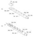
도 1은 본 발명의 실시 예에 따른 손가락 운동 장치의 개략도.
도 2는 본 발명의 실시 예에 따른 손가락 운동 장치의 분해도.
도 3은 본 발명의 실시 예에 따른 착용 모듈의 개략도.
도 4는 본 발명의 실시 예에 따른 굴곡 모듈의 분해도.
도 5는 본 발명의 실시 예에 따른 신전 모듈의 분해도.
도 6은 본 발명의 실시 예에 따른 조절부의 개략도.1 is a schematic view of a finger exercise device according to an embodiment of the present invention;
2 is an exploded view of a finger exercise device according to an embodiment of the present invention;
3 is a schematic view of a wear module according to an embodiment of the invention.
4 is an exploded view of a flex module according to an embodiment of the present invention;
5 is an exploded view of a shrink module according to an embodiment of the present invention.
6 is a schematic diagram of an adjuster according to an embodiment of the present invention;
이하, 첨부된 도면을 참조하여 본 발명의 실시 예를 상세히 설명한다. 그러나, 본 발명은 이하에서 개시되는 실시 예에 한정되는 것이 아니라 서로 다른 다양한 형태로 구현될 것이다. 단지 본 발명의 실시 예는 본 발명의 개시가 완전하도록 하고, 해당분야에서 통상의 지식을 가진 자에게 발명의 범주를 완전하게 알려주기 위해 제공되는 것이다. 도면은 실시 예를 설명하기 위해 그 크기가 과장될 수 있고, 도면상의 동일 부호는 동일한 요소를 지칭한다.Hereinafter, embodiments of the present invention will be described in detail with reference to the accompanying drawings. However, the present invention is not limited to the embodiments described below, but may be embodied in various forms. It is to be understood that both the foregoing general description and the following detailed description of the present invention are exemplary and explanatory and are intended to provide further explanation of the invention as claimed. The drawings may be exaggerated in size to illustrate the embodiments, and like reference numbers in the drawings indicate like elements.
본 발명의 실시 예에 따른 손가락 운동 장치는 사용자의 손가락 관절을 굴곡 또는 신전시키고, 이에 손가락을 운동시키는 장치이다. 이때, 손가락 운동 장치는 각 손가락 관절의 굴곡량을 정밀하게 조절하여, 사용자의 손가락 운동에 요구되는 다양한 동작을 구현할 수 있다.A finger exercise device according to an embodiment of the present invention is a device for flexing or extending a finger joint of a user and moving a finger thereon. At this time, the finger exercising apparatus can precisely control the amount of flexion of each finger joint, thereby realizing various operations required for the movement of the user's finger.
먼저, 본 발명의 실시 예를 설명함에 있어서, 굴곡과 신전과 굴곡량의 의미는 각각 다음과 같다. 굴곡은 신체부위간의 각도가 감소하는 관절운동을 의미하며, 특히 본 실시 예에서는 손을 구성하는 중수지절관절(MCP), 근위지절관절(PIP), 원위지절관절(DIP)의 각도를 감소시키는 손가락 운동 장치의 동작을 의미한다. 또한, 신전은 신체부위간의 각도가 증가하는 관절운동을 의미하며, 특히 본 실시 예에서는 중수지절관절(MCP), 근위지절관절(PIP), 원위지절관절(DIP)의 각도를 증가시키는 손가락 운동 장치의 동작을 의미한다. 또한, 굴곡량은 신체부위간의 각도가 감소되는 정도를 의미하며, 특히 본 실시 예에서는 중수지절관절(MCP), 근위지절관절(PIP), 원위지절관절(DIP)의 감소 또는 증가되는 각도를 의미한다.First, in explaining the embodiment of the present invention, the meaning of bending, extension, and bending amount are as follows. The flexion refers to the joint movement in which the angle between the body parts is reduced. In particular, in this embodiment, the angle of the MIP, the PIP, and the DIP of the hand are reduced Means the operation of the finger exercise device. In addition, the extension refers to the joint movement in which the angle between the body parts is increased. In particular, in this embodiment, the finger movement that increases the angle of the MIP, the PIP, Means the operation of the device. The amount of flexion refers to the degree of reduction of the angle between the body parts. In particular, in the present embodiment, a decrease or an increased angle of the MIP, the PIP, and the DIP it means.
도 1은 본 발명의 실시 예에 따른 손가락 운동 장치를 도시한 개략도 이고, 도 2는 본 발명의 실시 예에 따른 손가락 운동 장치를 도시한 분해도 이며, 도 3은 본 발명의 실시 예에 따른 착용 모듈을 도시한 개략도 이다. 또한, 도 4는 본 발명의 실시 예에 따른 굴곡 모듈의 분해도 이고, 도 5는 본 발명의 실시 예에 따른 신전 모듈의 분해도 이며, 도 6은 본 발명의 실시 예에 따른 굴곡 및 신전 조절부의 개략도 이다. 여기서, 도 3a는 본 발명의 실시 예에 따른 착용 모듈의 상부면을 도시한 개략도 이고, 도 3b는 본 발명의 실시 예에 따른 착용 모듈의 하부면을 도시한 개략도 이다. 또한, 도 6(a)는 본 실시 예에 따른 굴곡 및 신전 조절부에 와이어가 결속되기 전 상태를 도시한 개략도 이고, 도 6(b)는 본 실시 예에 따른 굴곡 및 신전 조절부에 와이어가 결속 된 상태를 도시한 개략도 이다.FIG. 1 is a schematic view showing a finger exercise device according to an embodiment of the present invention. FIG. 2 is an exploded view illustrating a finger exercise device according to an embodiment of the present invention. Fig. 5 is an exploded view of the extension module according to the embodiment of the present invention. FIG. 6 is a schematic view of a bending and extension adjusting unit according to an embodiment of the present invention. FIG. to be. 3A is a schematic view showing a top surface of a wear module according to an embodiment of the present invention, and FIG. 3B is a schematic view showing a bottom surface of a wear module according to an embodiment of the present invention. 6 (a) is a schematic view showing a state before the wires are coupled to the bending and extension adjusting unit according to the present embodiment, and Fig. 6 (b) And Fig.
도 1 내지 도 6을 참조하면, 본 발명의 실시 예에 따른 손가락 운동 장치는 사용자의 손이 착용되는 착용 모듈(100), 착용 모듈(100)의 일측에 배치되는 굴곡 모듈(200), 굴곡 모듈(200)이 배치된 착용 모듈(100)의 일측에 대향되는 착용 모듈(100)의 타측에 배치되는 신전 모듈(300), 각각의 일단이 착용 모듈(100)의 후술하는 손가락 마디부(120)들의 단부에 각각 연결되고, 각각의 타단이 굴곡 모듈(200)에 연결되는 복수개의 굴곡 와이어(w1) 및 각각의 일단이 착용 모듈(100)의 손가락 마디부(120)들의 복수의 위치에 각각 연결되고, 각각의 타단이 신전 모듈(300)에 연결되는 복수개의 신전 와이어(w2)를 포함한다. 여기서, 착용 모듈(100)에는 착용 모듈(100)의 손가락 마디부(120)에 형성되어 착용 모듈(100)의 굴곡량을 측정하는 제1 센서(710) 및 착용 모듈(100)의 손가락 마디부(120)의 단부에 형성되어 착용 모듈(100)에 가해지는 압력을 측정하는 제2 센서(720)가 구비될 수 있다.1 to 6, a finger exercise device according to an embodiment of the present invention includes a
또한, 손가락 운동 장치는 신전 모듈(300)의 반대측에서 굴곡 모듈(200)에 연결되는 베이스 모듈(400) 및 착용 모듈(100)과 굴곡 모듈(200)과 신전 모듈(300)에 연결되고, 제1 및 제2 센서(710, 720)로부터 전달받는 측정값에 따라 굴곡 모듈(200) 및 신전 모듈(300)의 동작을 제어하는 제어 모듈(500)을 더 포함할 수 있다.The finger exercise device is connected to the
본 실시 예에 따른 손가락 운동 장치에는 복수개의 굴곡 및 신전 와이어(w1, w2)가 구비된다. 굴곡 와이어(w1)들은 굴곡 모듈(200)의 후술하는 굴곡 조절부(230)에 연결되고, 굴곡 조절부(230)의 회전에 따라 손가락 마디부(120)들을 동시에 굴곡 또는 신전시킬 수 있다. 또한, 신전 와이어(w2)들은 신전 모듈(300)의 후술하는 신전 조절부(330)들에 각각 연결되고, 신전 조절부(330)들의 회전에 따라 손가락 마디부(120)들의 굴곡량을 각각 조절할 수 있다. 이때, 신전 와이어(w2)들은 신전 와이어(w2)들의 각각의 일단이 연결되는 착용 모듈(100)의 마디부(121, 122, 123)들에 대응하여 정해지는 신전 조절부(330a, 330b, 330c)에 각각 연결될 수 있다. 이에, 착용 모듈(100)은 손가락 마디부(120)들의 굴곡량을 목적하는 굴곡량으로 정밀하게 조절하여 사용자의 손가락 운동에 요구되는 다양한 동작을 구현할 수 있다.The finger exercising apparatus according to the present embodiment is provided with a plurality of curved and extended wires w1 and w2. The bending wires w1 are connected to the bending
착용 모듈(100)은 도 3에 도시된 바와 같이, 굴곡 모듈(200)과 신전 모듈(300)의 사이에 배치되는 손허리부(110), 손허리부(110)에 회전 가능하게 연결되고, 손가락을 각각 감싸도록 형성되는 복수개의 손가락 마디부(120) 및 손가락 마디부(120)들의 각각의 단부에 형성되는 복수개의 손가락 전단부(130) 를 포함할 수 있고, 착용 모듈(100)은 굴곡 모듈(200)과 신전 모듈(300)의 사이에서 수평방향 예컨대 전후방향(x축 방향)으로 배치된다. 여기서, 손가락 마디부(120)는 사용자의 엄지를 감싸는 엄지부(120a), 검지를 감싸는 검지부(120b), 중지를 감싸는 중지부(120c), 약지를 감싸는 약지부(120d) 및 소지를 감싸는 소지부(120e)를 포함한다. 그리고, 각각의 손가락 마디부(120: 120a, 120b, 120c, 120d, 120e)는 손가락의 첫 마디를 감싸는 제1 마디부(121: 121a, 121b, 121c, 121d, 121e), 손가락의 중간 마디를 감싸는 제2 마디부(122: 122b, 122c, 122d, 122e), 손가락의 끝 마디를 감싸는 제3 마디부(123: 123a, 123b, 123c, 123d, 123e)를 포함한다. 본 실시 예에서는 착용된 사용자의 손을 지지 가능하도록, 장갑 형상으로 제작되는 착용 모듈(100)을 예시한다. 또한, 착용 모듈(100)의 각 구성부가 손 관절의 움직임에 따라 목적하는 방향으로 자유롭게 움직일 수 있도록, 착용 모듈(100)의 각 구성부의 사이에는 각 구성부를 연결하는 관절부(140)가 마련될 수 있다. 관절부(140)는 신축 가능한 재질로 마련되거나 또는 유연한 재질로 마련될 수 있고, 이에 착용 모듈(100)의 각 구성부는 손 관절의 움직임에 따라 목적하는 방향으로 자유롭게 움직일 수 있다. 한편, 본 실시 예에서는 전술한 착용 모듈(100)을 특별히 한정되지 않는다. 즉, 착용 모듈(100)은 사용자의 손이 착용 가능하고, 적어도 사용자의 손가락을 감싸 지지할 수 있는 다양한 형상 및 구조로 제작될 수 있다. 예컨대, 착용 모듈(100)은 사용자의 손이 착용되어 굴곡 가능하도록 형성되는 링크 장치일 수 있다.As shown in FIG. 3, the wearing
상술한 손가락 운동 장치의 손가락 마디부(120) 및 손가락 전단부(130) 각각은 후술하는 굴곡 와이어(w1)와 신전 와이어(w2)에 의해 후술하는 굴곡 모듈(200)의 굴곡 조절부(230)와 신전 모듈(300)의 신전 조절부(300)에 연결된다. 굴곡 와이어(w1)들은 착용 모듈(100)의 하측에서 각각의 일단이 손가락 전단부(130)들에 연결되며, 각각의 타단이 후술하는 굴곡 조절부(230)에 연결될 수 있다. 또한, 신전 와이어(w2)들은 착용 모듈(100)의 상측에서 각각의 일단이 손가락 마디부(120)들에 각각 연결되며, 각각의 타단이 후술하는 신전 조절부(330)에 연결될 수 있다. 여기서, 신전 와이어(w2)들의 각각의 일단은 제1 마디부(121)들과 제2 마디부(122)들과 제3 마디부(123)들에 각각 연결될 수 있다. 각 와이어(w: w1, w2)에는 각 와이어의 적어도 일부를 감싸도록 튜브(미도시)가 마련될 수 있다. 튜브(미도시)는 후술하는 굴곡 모듈(200)과 신전 모듈(300)의 제1 및 제2 하우징(210)에 일단이 각각 연결되고, 와이어(w)들의 길이방향을 각각 연장 형성될 수 있다. 튜브(미도시)의 각각의 끝단은 손가락 마디부(120)에 가까운 손허리부(110)의 소정 위치에 각각 장착 고정되거나 혹은 이격 배치되어 각 와이어(w)가 움직이는 경로를 형성할 수 있다. 한편, 각 조절부(230, 330)는 축회전하며 그 외면을 통하여 각 와이어(w)를 둘러 감아 당길 수 있다. 상세하게는, 굴곡 와이어(w1)는 착용 모듈(100)의 손가락 전단부(130)들에 연결되어 이를 하측 방향으로 당기고, 신전 와이어(w2)는 손가락 마디부(120)들에 각각 연결되어 이를 상측 방향으로 당길 수 있다. 이때, 제1 마디부(121)와 제2 마디부(122)와 제3 마디부(123)에 연결되는 신전 와이어(w2)들을 구분하여 제어할 수 있도록, 신전 조절부(330)는 적어도 세 개 이상 구비된다. 이에, 제1 마디부(121)와 제2 마디부(122)와 제3 마디부(123)에 연결되는 신전 와이어(w2)들은 각각 구분되어 복수개의 신전 조절부(330)에 연결된다. 이로 인해, 착용 모듈(100)은 굴곡 조절부(230)의 회전에 의해 굴곡 또는 신전되는 과정에서 신전 조절부(330)의 회전에 의해 착용 모듈(100)에 구비된 각 관절부(140)들의 굴곡량이 각각 조절될 수 있다. 이처럼, 각 조절부(230, 330)의 회전에 의해 착용 모듈(100)에 착용된 사용자의 손가락 관절은 효과적인 관절 운동이 가능하다.Each of the
굴곡 모듈(200)은 착용 모듈(100)의 하측에 배치되어 내부에 구비된 굴곡 조절부(230)를 회전시켜 굴곡 조절부(230)에 연결된 착용 모듈(100)을 굴곡 또는 신전시키는 역할을 한다. 굴곡 모듈(200)은 도 4에 도시된 바와 같이, 착용 모듈(100)의 길이방향에 교차하는 방향으로 연장 형성되고, 내부공간을 가지는 제1 하우징(210), 상하방향(z축 방향)으로 연장 형성되고, 제1 하우징(210)의 길이방향의 양 단부 중 어느 한 단부에 장착되는 제1 하우징 지지부(220), 제1 하우징(210)의 길이방향으로 연장 형성되고, 제1 하우징(210)의 길이방향으로 제1 하우징(210)과 제1 하우징 지지부(220)를 관통하여 장착되며, 양 단부가 제1 하우징(210)과 제1 하우징 지지부(220)의 외측에 각각 위치하는 굴곡 조절부(230) 및 제1 하우징(210)의 반대측에서 제1 하우징 지지부(220)에 착탈 가능하게 장착되고, 굴곡 조절부(230)에 연결되어 굴곡 조절부(230)를 회전시키는 제1 구동부(240)를 포함할 수 있다.The
제1 하우징(210)은 착용 모듈(100)의 길이방향에 교차하는 방향 예컨데 좌우방향(y축 방향)으로 연장 형성되고, 내부에 공간을 가지는 박스 형상으로 제작될 수 있다. 하지만, 이에 한정되지 않고, 제1 하우징(210)은 내부에 굴곡 조절부(230)가 배치될 수 있는 소정 공간을 가지는 다양한 형상으로 제작될 수 있다. 또한, 제1 하우징(210)은 전방 또는 후방을 향하는 측면 중 적어도 하나의 측면이 개방되도록 형성될 수 있고, 개방된 측면에는 제1 하우징의 내부가 비칠 수 있도록 투과창(미도시)이 마련될 수 있다. 이에, 제1 하우징(210)의 내부에 배치되는 굴곡 조절부(230)의 동작상태를 사용자가 용이하게 점검할 수 있다. 제1 하우징(210)의 전방을 향하는 측면에는 굴곡 와이어(w1)의 움직임을 가이드 하도록 제1 가이드부재(250)가 배치될 수 있다. 제1 가이드 부재(211)는 좌우방향을 연장 형성되는 바 형상으로 제작될 수 있다. 이때, 제1 가이드 부재(211)에는 제1 가이드 부재(211)를 전후방향으로 관통하여 형성되는 복수개의 제1 가이드 홀(212)이 마련될 수 있다. 제1 가이드 홀(212)은 제1 가이드 부재(211)의 길이방향을 따라 이격 배치되고, 손가락 운동 장치에 마련되는 굴곡 와이어(w1)의 개수에 대응하는 개수만큼 형성된다. 본 실시 예에서는 착용 모듈(100)의 손가락 전단부(130)의 개수에 대응하여 적어도 다섯 개 이상의 제1 가이드 홀(212)이 마련된다. 마련된 제1 가이드 홀(212)을 통하여 굴곡 와이어(w1)는 제1 하우징(210)의 외부에서 내부로 진입 가능하고, 이에 제1 하우징(210)의 외부에 위치하는 착용 모듈(100)에 제1 하우징(210)의 내부에 위치하는 굴곡 조절부(230)를 연결시킬 수 있다. 제1 가이드 부재(211)는 제1 하우징(210)에 예컨대 볼트결합 방식으로 결합될 수 있고, 이에 제1 가이드 부재(211)는 제1 하우징(210)으로부터 용이하게 탈착 될 수 있다.The
제1 하우징 지지부(220)는 상하방향으로 연장 형성되고 , 제1 하우징(210)의 길이방향의 양 단부 중 어느 한 단부에 장착되어 굴곡 모듈(200)이 신전 모듈(300) 및 베이스 모듈(400)의 각각에 연결될 때, 각각에 연결 지지되는 역할을 한다. 예컨대, 제1 하우징 지지부(220)는 소정 면적과 소정 폭을 가지는 사각판 형상으로 제작되어 제1 하우징(210)의 우측 단부에 장착되고, 그 상부면과 하부면을 통하여 각각 신전 모듈(300)과 베이스 모듈(400)에 접촉 연결될 수 있다. 제1 하우징 지지부(220)는 제1 하우징 지지부(220)의 상부면이 제1 하우징(210)으로부터 상측으로 소정 길이 이격 위치하고, 하부면이 제1 하우징(210)으로부터 하측으로 소정 길이 이격 위치하도록 그 상하방향의 길이가 형성될 수 있다. 이에, 굴곡 모듈(200)이 후술하는 신전 모듈(300) 및 베이스 모듈(400)과 연결되었을 때, 각각의 사이에 이격 공간이 마련될 수 있고, 특히 굴곡 모듈(200)과 신전 모듈(300)의 사이에 착용 모듈(100)이 배치될 수 있는 공간이 마련될 수 있다. 제1 하우징 지지부(220)의 전후방향으로의 길이는 제1 하우징(210)의 전후방향으로의 길이보다 길게 형성될 수 있다. 이에, 제1 하우징(210)에 장착되어 그 단부를 커버 가능하고, 제1 하우징 지지부(220)에 제1 구동부(240)가 장착되는 소정 면적을 마련할 수 있다. 한편, 전술한 제1 하우징 지지부(220)는 이에 한정되지 않고, 제1 하우징(210)에 장착되어 그 단부를 커버 가능하고 제1 하우징(210)의 상하측으로 연장되는 소정 면적과, 소정 두께를 가지는 다양한 형상으로 제작될 수 있다.The first
한편, 제1 하우징 지지부(220)와 제1 하우징(210)은 일체형으로 제작될 수 있고, 분리형으로 제작될 수 있다. 제1 하우징 지지부(220)와 제1 하우징(210)이 분리형으로 제작되는 경우, 제1 하우징 지지부(220)는 제1 하우징(210)에 탈착 가능하게 장착될 수 있고, 예컨대 볼트결합 방식으로 장착될 수 있다.Meanwhile, the first
굴곡 조절부(230)는 제1 하우징(210)의 길이방향 예컨대 좌우방향으로 연장 형성되고, 제1 하우징(210)과 제1 하우징 지지부(220)를 좌우방향으로 관통하여 제1 하우징(210)과 제1 하우징 지지부(220)에 장착 지지될 수 있다. 이때, 굴곡 조절부(230)는 좌우방향의 중심축을 중심으로 축회전이 가능하도록 제1 하우징(210)과 제1 하우징 지지부(220)에 장착된다. 이를 위해, 굴곡 조절부(230)와 제1 하우징(210) 및 제1 하우징 지지부(220)의 사이에는 베어링부(미도시)가 마련될 수 있다. 장착된 굴곡 조절부(230)의 양 단부는 제1 하우징(210)과 제1 하우징 지지부(220)의 외측으로 소정길이 각각 돌출된다.The bending
이하, 도 4 및 도 6을 참조하여, 굴곡 조절부(230)를 설명한다.Hereinafter, the bending
굴곡 조절부(230)는 제1 하우징(210)의 길이방향 즉, 좌우방향으로 연장 형성되고, 내부에 길이방향으로 중공(232)이 형성되며, 중공(232)과 연결되어 굴곡 와이어(w1)가 진입되는 복수개의 개구(233)를 구비하는 제1 축 부재(231), 제1 하우징 지지부(220)에 가까운 제1 축 부재(231)의 단부에 형성되고, 제1 구동부(240)와 연결되는 제1 소켓(235), 제1 축 부재(231)의 나머지 단부에 형성되어 제1 축 부재(231)의 나머지 단부에 노출된 중공(232)의 단부를 개폐시키는 제1 압착부재(234)를 포함할 수 있다.The
제1 축 부재(231)는 중공형의 막대 형상으로 제작될 수 있다. 본 실시 예에서는 제1 축 부재(231)의 축회전이 용이하고, 제1 축 부재(231)의 외면을 통해 굴곡 와이어(W1)를 둘러 감기 용이하도록 원통형의 외면을 가지는 막대 형상의 제1 축 부재(231)를 예시한다. 제1 축 부재(231)는 제1 하우징(210)에 장착되어 그 양단이 제1 하우징(210)과 제1 하우징 지지부(220)의 외측에 노출되도록 그 길이가 형성될 수 있다.The
중공(232)은 제1 축 부재(231)는 내부에 형성되어 제1 축 부재(231)의 길이방향으로 연장된다. 개구(233)는 제1 축 부재(231)의 길이방향에 교차하는 방향 즉, 제1 축 부재(231)의 외면에서 중공(232)을 향하는 방향으로 제1 축 부재(231)를 관통하고, 제1 축 부재(231)의 길이방향으로 이격되어 복수개 형성된다. 형성된 개구(233)를 통하여 굴곡 와이어(w1)의 적어도 일부가 중공(232)내로 진입될 수 있다. 개구(233)는 착용 모듈(100)의 손가락 전단부(130)에 연결된 굴곡 와이어(w1)의 개수에 대응하는 개수만큼 형성된다. 본 실시 예에서는 제1 축 부재(231)의 다섯 위치에 형성되는 개구(233)를 예시한다. 하지만, 이에 한정되지 않고, 사용자가 목적하는 개수만큼 다양하게 형성될 수 있다.The hollow portion 232 is formed in the
압착부재(234)는 제1 축 부재(231)의 양 단부 중 제1 하우징 지지부(220)에서 먼 제1 축 부재(231)의 단부, 즉 제1 축 부재(231)의 좌측 단부에 형성되어 굴곡 와이어(w1)를 제1 축 부재(231)에 고정시키는 역할을 한다. 이를 위해, 제1 축 부재(231)의 좌측 단부에는 소정 영역에 단차면(236)이 형성될 수 있고, 형성된 단차면(236)에는 중공(232)의 단부가 위치하여 중공(232)의 내부를 외측으로 노출시킨다. 압착부재(234)는 제1 축 부재(231)의 단차에 형성된 중공(232)의 단부를 개폐시키도록 제1 축 부재(231)의 단차면(236)에 탈착 가능하게 장착된다. 예컨대, 압착부재(234)는 단차면(236)에 볼트결합 방식으로 장착될 수 있다. 중공(232)내로 진입한 굴곡 와이어(w1)는 적어도 일부가 중공(232)의 단부를 통과하여 단차면(236) 상에 놓여질 수 있고, 압착부재(234)는 단차면(236)에 장착되어 단차면(236) 상에 놓여진 굴곡 와이어(w1)를 밀착 고정시킬 수 있다. 즉, 굴곡 와이어(w1)는 제1 축 부재(231)의 개구(233)를 통과하여 중공(232) 내로 진입되고, 중공(232)의 단부에서 제1 압착부재(234)에 압착 고정되어 굴곡 조절부(230)에 연결될 수 있다.The pressing
한편, 압착부재(234)는 그 형성 위치에 의해 사용자가 용이하게 다룰 수 있고, 이에 굴곡 조절부(230)에 연결 고정되는 굴곡 와이어(w1)의 길이 조절을 보다 용이하게 할 수 있다. 예를 들어, 굴곡 조절부(230)에 연결 고정된 굴곡 와이어(w1)의 길이조절이 요구되는 경우, 우선 압착부재(234)를 단차면(236) 상에서 탈착시킨다. 이후, 중공(232)의 단부에 놓여진 굴곡 와이어(w1)의 단부를 당기거나 밀어서 굴곡 와이어(w1)의 길이를 목적하는 만큼 조절하고, 탈착된 압착부재(234)를 단차면(236)에 장착하여 굴곡 와이어(w1)를 밀착 고정시킨다. 즉, 굴곡 조절부(230)는 제1 하우징(210) 외측에 굴곡 와이어(w1)를 고정시키는 압착부재(234)를 마련하여 굴곡 와이어(w1)의 길이를 굴곡 모듈(200)의 분리 없이 사용자가 요구하는 다양한 길이로 용이하게 조절 할 수 있다.On the other hand, the pressing
소켓(235)은 제1 하우징 지지부(220)에 가까운 제1 축 부재(231)의 단부 즉, 제1 축 부재(231)의 우측단부에서 제1 축 부재(231)의 길이방향으로 소정 길이 연장 형성된다. 형성되는 소켓(235)에 후술하는 제1 구동부(240)의 구동축(미도시)이 삽입 연결된다. 이에, 제1 구동부(240)의 구동축(미도시)으로부터 전달되는 회전력이 소켓(235)을 통하여 제1 축 부재(231)에 전달될 수 있다. 이에, 제1 축 부재(231)는 제1 축 부재(231)에 연결된 제1 구동부(240)로부터 구동력을 전달받아 길이방향 중심축을 중심으로 축회전하며, 그 외면에 굴곡 와이어(w1)를 둘러 감거나 풀 수 있다.The
제1 구동부(240)는 제1 하우징(210)의 반대측에서 제1 하우징 지지부(220)에 착탈 가능하게 장착되고, 굴곡 조절부(230)의 소켓(235)에 연결되어 굴곡 조절부(230)를 회전시키는 역할을 한다. 예컨대, 제1 구동부(240)는 볼트결합 방식으로 제1 하우징 지지부(220)에 탈착 가능하게 장착될 수 있다. 구동부(240)에는 모터(미도시), 감속기(미도시), 구동축(미도시)이 구비될 수 있다. 구동부(240)는 굴곡 모듈(200)의 외부에 마련되거나 혹은 내부에 구비되는 전원공급원(미도시)으로부터 전원을 공급받아 모터가 회전하면, 모터에 연결된 감속기를 이용하여 목적하는 회전수로 감속시켜, 감속기에 연결된 구동축으로 회전력을 출력한다. 출력되는 회전력은 소켓(235)를 통하여 제1 축 부재(231)에 전달, 제1 축 부재(231)를 회전시키는데 이용된다. 한편, 본 실시 예에서는 제1 구동부(240)의 구성요소 및 각 구성요소들의 결합관계를 특별히 한정하지 않는다. 즉, 제1 구동부(240)는 제1 하우징 지지부(220)에 탈착 가능하도록 그 몸체가 형성되고, 몸체의 내부에 제1 축 부재(231)에 회전력을 공급 가능하도록 다양한 구성요소 마련되어 다양한 방식으로 결합될 수 있다.The
신전 모듈(300)은 착용 모듈(100)의 상측에 배치되어 내부에 구비된 신전 조절부(330: 330a, 330b, 330c)를 회전시켜 신전 조절부(310)에 연결된 착용 모듈(100)의 굴곡량을 조절하는 역할을 한다. 신전 모듈(300)은 도 5에 도시된 바와 같이, 착용 모듈(100)의 길이방향에 교차하는 방향 예컨대 좌우방향으로 연장 형성되고, 내부공간을 가지는 제2 하우징(310), 상하방향으로 연장 형성되고, 제1 하우징 지지부(220)에 가까운 제2 하우징(310)의 단부 즉, 제2 하우징의 우측단부에 장착되는 제2 하우징 지지부(320), 제2 하우징(310)의 길이방향 즉, 좌우방향으로 연장 형성되고, 제2 하우징(310)의 길이방향으로 제2 하우징(310)과 제2 하우징 지지부(320)를 관통하여 장착되며, 양 단부가 제2 하우징(310)과 제2 하우징 지지부(320)의 외측에 각각 위치하는 신전 조절부(330), 및 제2 하우징(310)의 반대측에서 제2 하우징 지지부(320)에 착탈 가능하게 장착되고, 신전 조절부(330)에 연결되어 신전 조절부(330)를 회전시키는 제2 구동부(340)를 포함할 수 있다.The
여기서, 본 실시 예에 따른 신전 모듈(300)은 상술한 굴곡 모듈(200)과 그 형상 및 구성이 유사하다. 따라서, 이하에서는 굴곡 모듈(200)과 구분되는 신전 모듈(300)의 구성 및 특징을 중심으로 설명한다.Here, the
제2 하우징(310)은 좌우방향으로 연장 형성되고, 내부에 신전 조절부(330)가 배치될 수 있는 공간이 마련된다. 본 실시 예에서는 박스 형상으로 제작되는 제2 하우징(310)을 예시한다. 이때, 제2 하우징(310)의 전후방향 길이는 제1 하우징(210)의 전후방향 길이보다 길게 형성될 수 있다. 이에 제2 하우징(310)의 내부에는 복수개의 신전 조절부(330)가 배치되는 공간이 마련될 수 있다. 제2 가이드 부재(311)는 제2 하우징(310)의 전방을 향하는 측면에 탈착 가능하게 장착된다. 제2 가이드 부재(311)는 좌우방향으로 길이를 가지며, 바 형상으로 제작될 수 있다. 제2 가이드 부재(311)에는 제2 가이드 부재(311)를 전후방향으로 관통하여 제2 가이드 홀(312)이 형성될 수 있다. 제2 가이드 홀(312)은 제2 가이드 부재(311)의 길이방향을 따라 서로 이격되어 복수개 형성될 수 있다. 본 실시 예에서는, 착용 모듈(100)의 각 손가락 마디부(120)에 연결되는 신전 와이어(w2)의 개수에 대응하여, 제2 가이드 부재(311)에는 적어도 열 내개의 제2 가이드 홀(312)이 형성될 수 있다. 제2 가이드 홀(312)을 통하여 신전 와이어(w2)가 제2 하우징(310)의 외부에서 내부로 진입될 수 있다.The
제2 하우징 지지부(320)는 상하방향으로 연장 형성되고, 제2 하우징(310)의 우측 단부에 탈착 가능하게 장착될 수 있다. 본 실시 에에서는 사각판 형상으로 제작되는 제2 하우징 지지부(320)를 예시한다. 하지만 이에 한정되지 않고, 제2 하우징의 연장 방향의 단부에 장착되어 제2 하우징(310)의 상하측으로 소정 길이 연장되고, 제2 구동부가 장착될 수 있는 소정 면적을 가지는 다양한 형상으로 제작될 수 있다. 제2 하우징 지지부(320)의 상부면은 제2 하우징(310)의 상부면과 동일면상에 위치하거나 혹은, 제2 하우징(310)의 상부면으로부터 상측으로 소정 거리 이격되어 위치할 수 있다. 또한, 제2 하우징 지지부(320)의 하부면은 제2 하우징(310)의 하부면으로부터 하측으로 소정 거리 이격되어 위치할 수 있다. 제2 하우징 지지부(320)의 하부면은 제 1 하우징 지지부(310)의 상부면에 접촉 연결될 수 있다.The second
신전 조절부(330)는 좌우방향으로 연장 형성되고, 제2 하우징(310) 및 제2 하우징 지지부(320)를 좌우방향으로 관통하여 배치될 수 있다. 신전 조절부(330)와 제2 하우징(310) 및 제2 하우징 지지부(320)의 사이에는 베어링부(미도시)가 마련될 수 있고, 이에 신전 조절부(330)는 좌우방향 중심축을 중심으로 원활하게 축회전 될 수 있다. 신전 조절부(330)의 양 단부는 제2 하우징(310)과 제2 하우징 지지부(320)의 외측으로 소정 길이 돌출된다.The
신전 조절부(330)는 복수개 구비되어, 제2 하우징(310)의 적어도 세 위치에 설치될 수 있다. 상세하게는, 신전 조절부(330)는 중수지절관절 조절부(330a)와 근위지절관절 조절부(330b)와 원위지절관절 조절부(330c)를 포함하고, 제2 하우징(310) 내에서 전후방향으로 서로 이격되어 배치될 수 있다. 이때, 제2 하우징(310)의 전방으로부터 후방을 향하는 방향으로 중수지절관절 조절부(330a), 근위지절관절 조절부(330b), 원위지절관절 조절부(330c)의 순서대로 배치될 수 있다. 이에, 신전 와이어(w2)들 중 제1 마디부(121)들에 연결된 신전 와이어(w2)들은 중수지절관절 조절부(330a)에 연결되고, 제2 마디부(122)들에 연결된 신전 와이어(w2)들은 근위지절관절 조절부(330b)에 연결될 수 있다. 또한, 제3 마디부(123)들에 연결된 신전 와이어들은 원위지절관절 조절부(330c)에 연결될 수 있다.A plurality of
상술한 신전 조절부(330: 330a, 330b, 330c)는 제2 하우징(310)의 길이방향으로 연장 형성되고, 내부에 길이방향으로 중공(332)이 형성되며, 중공(332)과 연결되어 신전 와이어(w2)가 진입되는 복수개의 개구(333)를 구비하는 제2 축 부재(331), 제2 하우징 지지부(320)에 가까운 제2 축 부재(331)의 단부에 형성되고, 제2 구동부(340)와 연결되는 제2 소켓(335) 및 제2 축 부재(331)의 나머지 단부에 형성되어 제2 축 부재(331)의 나머지 단부에 노출된 중공(332)의 단부를 개폐시키는 제2 압착부재(334)를 포함할 수 있다. 이때, 신전 와이어(w2)는 제2 축 부재(331)의 개구(333)를 통과하여 중공(332) 내로 진입되고, 중공(332)의 단부에서 제2 압착부재(334)에 압착되어 고정될 수 있다.The
여기서, 각각의 신전 조절부(330)는 도 6에 도시된 바와 같이, 상술한 굴곡 조절부(230)와 그 형상, 구성요소 및 구성요소의 결합방식이 동일하다. 따라서, 이에 대한 상세한 설명은 생략한다.Here, as shown in FIG. 6, each of the
제2 구동부(340)는 제 2 하우징(310)의 반대측에서 제1 하우징 지지부(320)에 착탈 가능하게 장착되고, 복수개의 신전 조절부(330)에 각각 연결되어 신전 조절부(330)를 회전시키는 역할을 한다. 본 실시 예에서는 제2 구동부(340)의 구성요소 및 각 구성요소들의 결합관계를 특별히 한정하지 않는다. 즉, 제2 구동부(340)는 제2 하우징 지지부(320)에 탈착 가능하도록 그 몸체가 형성되고, 몸체의 내부에 제2 축 부재(331: 331a, 331b, 331c)들에 회전력을 각각 공급 가능하도록 다양한 구성요소 마련되어 다양한 방식으로 결합될 수 있다.The
베이스 모듈(400)은 굴곡 모듈(200)의 하측에 배치되고, 상부면이 굴곡 모듈(200)의 제1 하우징 지지부(220)의 하부면에 접촉 연결되며, 굴곡 모듈(200)과 이에 연결된 신전 모듈(300)을 지지하는 역할을 한다. 즉, 베이스 모듈(400)은 굴곡 모듈(200)과 신전 모듈(300)이 안정적으로 장착되어 지지될 수 있도록 손가락 운동 장치의 무게중심부 역할을 하는 구성부이다. 베이스 모듈(400)은 좌우방향으로 연장 형성되는 육면체 블록 형상으로 제작될 수 있다. 하지만, 이에 한정되지 않고, 베이스 모듈(400)은 바닥면에 소정 면적을 가지는 다양한 형상의 블록으로 제작될 수 있다.The
제어 모듈(500) 예컨대 무선제어 모듈은 신전 모듈(300)의 상부면에 배치되고, 착용 모듈(100)과 굴곡 모듈(200)과 신전 모듈(300)에 연결되어 굴곡 조절부(230)와 신전 조절부(330)의 회전을 제어할 수 있다. 본 실시 예에 따른 손가락 운동 장치를 운용함에 있어서, 햅틱 또는 증강현실을 구현할 수 있도록, 제어 모듈(500)에 내장되는 운용 시스템에는 햅틱 또는 증강현실을 구현할 수 있는 다양한 시스템이 적용될 수 있다. 이에, 손가락 운동 장치는 사용자의 손가락 관절을 제어 모듈(500)의 제어에 의해 효과적으로 운동시킬 수 있다.The
한편, 베이스 모듈(400)과 굴곡 모듈(200)과 신전 모듈(300)이 서로 착탈 가능하게 장착되도록, 베이스 모듈(400)과 굴곡 모듈(200)과 신전 모듈(300)의 각각의 사이에는 상호 대응되는 위치에 각각 고정부(600)가 구비될 수 있다.Between the
이하, 도 1 및 도 2를 참조하여, 본 실시 예에 따른 고정부(600)를 설명한다.Hereinafter, the fixing
고정부(600)는 전후방향으로 연장 형성되고, 상하방향으로 각각 이격되어 배치되는 상하부 브라켓(610, 620), 상부 브라켓(610)의 일측을 상하방향으로 관통하여 장착되고, 하측으로 연장되며, 외주면에 나사산이 형성되는 상부 결합축(630), 상부 결합축(630)의 길이방향 중심축에 정렬되도록 하부 브라켓(620)의 일측을 상하방향으로 관통하여 장착되고, 상측으로 연장 형성되며, 상측으로 개방된 내부공간과 내부공간의 내측면에 나사산을 구비하는 하부 결합축(640)을 포함할 수 있다. 이때, 하부 결합축(640)은 길이방향 중심축을 중심으로 축회전 가능하도록 하부 브라켓(620)에 장착될 수 있다.The fixing
상부 브라켓(610)은 제2 하우징(310)의 반대측에 위치하는 제2 하우징 지지부(320)의 측면의 하부 및 제1 하우징(210)의 반대측에 위치하는 제1 하우징 지지부(220)의 측면의 하부에 각각 장착될 수 있다. 하부 브라켓(620)은 제1 하우징(210)의 반대측에 위치하는 제1 하우징 지지부(220)의 측면의 상부 및 제1 하우징 지지부(220)에 가까운 베이스 모듈(400)의 측면에 각각 장착될 수 있다. 상하부 브라켓(610, 620)은 좌우방향으로 소정 두께를 가지며, 전후방향의 중심위치가 양 단부에 비하여 두껍게 형성될 수 있다. 상하부 브라켓(610, 620)의 전후방향의 중심위치를 관통하여 상부 결합축(630)과 하부 결합축(640)이 각각 장착될 수 있다. 상부 결합축(630)은 원통형으로 제작되고, 그 외주면에 나사산이 형성된다. 이에 대응하여, 하부 결합축의 내부공간은 상부 결합축(630)이 삽입 가능하도록 원통형으로 형성되고, 그 내측면에 상부 결합축(630)의 나사산과 결합 고정되도록 나사산이 형성된다. 고정부(600)의 결합방식은 다음과 같다. 제2 하우징 지지부(320)의 하부면과 제1 하우징 지지부(220)의 상부면을 접촉시킨다. 또한, 제1 하우징 지지부(220)의 하부면과 베이스 모듈(400)의 상부면을 서로 접촉시킨다. 이에 각각의 제2 하우징 지지부(320)와 제1 하우징 지지부(220)에 형성된 상부 결합축(630)이 각각의 상부 결합축(630)에 대응하는 위치에 각각 형성된 하부 결합축(640)의 내부공간으로 진입된다. 이와 동시에, 하부 결합축(640)을 축회전시켜 상부 결합축(630)과 하부 결합축(640)을 결합시킨다. 이에, 베이스 모듈(400)과 굴곡 모듈(200)과 신전 모듈(300)은 결합될 수 있다.The
본 실시 예에 따른 손가락 운동 장치에는 착용 모듈(100)의 움직임을 측정 가능하도록 센서부(700; 710, 720)가 마련될 수 있다. 제1 센서(710)는 착용 모듈(100)의 손가락 마디부(120)의 외측면에 손가락 마디부(120)의 길이방향을 따라 형성되어, 각 관절부(140)의 굴곡량을 측정할 수 있다. 제1 센서(710)는 각각의 손가락 마디부(120)에 복수개 형성될 수 있고, 각각의 손가락 마디부(120) 중 어느 하나의 손가락 마디부(120)에 형성될 수 있다. 제1 센서(710)에는 일반적인 와이어 센서가 적용될 수 있다. 제2 센서(720)는 착용 모듈(100)의 손가락 전단부(130)의 외측면의 하부에 형성되어, 착용 모듈(100)의 손가락 전단부에 가해질 수 있는 압력을 측정한다. 예컨대, 착용 모듈(100)이 굴곡되어 손가락 전단부(130)가 손허리부(110)에 접촉되는 경우 발생되는 압력을 측정할 수 있다. 하지만, 이에 한정되지 않고, 제2 센서(710)는 착용 모듈(100)의 다양한 위치에 마련되어 사용자가 요구하는 다양한 위치의 압력값을 측정 가능하다. 제2 센서(720)에는 일반적인 압력 센서가 적용될 수 있다. 제1 및 제2 센서(710, 720)로부터 측정되는 착용 모듈(100)의 굴곡량 및 압력값은 제어 모듈(500)로 전달되어 제어 모듈(500)의 제어에 이용될 수 있다. 즉, 구비되는 센서(710, 720)들은 착용 모듈(100)의 굴곡 및 신전 과정에서 착용 모듈(100)의 굴곡량과 착용 모듈(100)에 가해지는 압력을 검출하고, 측정값 제어 모듈(500)에 전달한다. 제어 모듈(500)은 제1 센서(710)와 제2 센서(720)로부터 검출되는 측정값에 따라 굴곡 조절부(230)와 신전 조절부(330)의 회전을 제어할 수 있다.
The finger exercising apparatus according to the present embodiment may be provided with a sensor unit 700 (710, 720) so as to measure the motion of the
이하, 본 실시 예에 따른 손가락 운동 장치의 운용 상태를 설명한다.Hereinafter, the operation state of the finger exercise device according to the present embodiment will be described.
굴곡 모듈(200)의 제1 구동부(240)를 구동시켜 이에 연결된 굴곡 조절부(230)를 일 방향으로 회전시킨다. 굴곡 조절부(230)의 회전에 의해 굴곡 조절부(230)의 외면에 굴곡 와이어(w1)가 감겨지고, 이에 굴곡 와이어(w1)에 연결된 착용 모듈(100)의 손가락 전단부(130)가 굴곡 와이어(w1)의 길이방향을 따라 하측으로 당겨진다. 이에, 착용 모듈(100)은 굴곡된다.The
이와 동시에, 신전 모듈(300)의 제2 구동부(340)를 구동시켜 이에 연결된 신전 조절부(330)를 일 방향으로 회전시킨다. 이때, 사용자가 요구하는 다양한 굴곡량을 착용 모듈(100)의 관절부(140)에 각각 제공하기 위해 중수지절관절 조절부(330a), 근위지절관절 조절부(330b), 원위지절관절 조절부(330c)의 회전량을 서로 다르게 제어할 수 있다. 신전 조절부(330)의 회전에 의해 신전 조절부(330)의 외면에 신전 와이어(w2)가 감겨지고, 이에 신전 와이어(w2)에 연결된 착용 모듈(100)의 손가락 마디부(120)가 신전 와이어(w2)의 길이방향을 따라 상측으로 당겨진다. 이때, 제1 마디부(121)와 제2 마디부(122)와 제3 마디부(123)는 각각 중수지절관절 조절부(330a), 근위지절관절 조절부(330b), 원위지절관절 조절부(330c)의 회전량에 따라 상측으로 당겨지는 힘이 서로 달라질 수 있다. 신전 와이어(w2)의 움직임에 의해 착용 모듈(100)에는 굴곡에 저항하는 힘이 가해지고, 이에 착용 모둘(100)의 굴곡량이 조절될 수 있다.At the same time, the
한편, 착용 모듈(100)은 착용 모듈(100)에 마련된 센서부(700)에 의해 그 굴곡량과 압력이 측정되고, 이는 제어 모듈(500)로 전달되어, 손가락 운동 장치가 착용 모듈(100)의 굴곡 및 신전 움직임을 보상하는 데에 이용된다.The bending amount and the bending pressure of the
본 발명의 실시 예에 따른 손가락 운동 장치는 손가락 전단부(130)에 연결된 굴곡 와이어(w1)를 이용하여 착용 모듈(100)에 착용된 사용자의 손가락을 굴곡 시킨다. 이와 동시에, 각각의 손가락 마디부(120)에 연결된 신전 와이어(w2)를 이용하여 착용 모듈(100)의 관절부(140)의 굴곡량을 정밀하게 조절하여 착용 모듈(100)에 착용된 사용자의 손가락 관절을 효과적으로 운동시킬 수 있다.
The finger exercising apparatus according to the embodiment of the present invention flexes a user's finger worn on the
한편, 본 발명의 상기 실시 예는 그 설명을 위한 것이며, 그 제한을 위한 것이 아니다. 또한, 본 발명이 해당하는 기술 분야에서의 업자는 본 발명의 기술 사상의 범위 내에서 다양한 실시 예가 가능함을 이해할 수 있을 것이다.
It should be noted that the above-described embodiments of the present invention are for explanation purposes only, and are not for the purpose of limitation. It is to be understood that various modifications may be made by those skilled in the art without departing from the scope of the present invention.
w1: 굴곡 와이어w2: 신전 와이어
100: 착용 모듈120: 손가락 마디부
130: 손가락 전단부200: 굴곡 모듈
230: 굴곡 조절부300: 신전 모듈
330a: 중수지절관절 조절부330b: 근위지절관절 조절부
330c: 원위지절관절 조절부600: 고정부
700: 센서부w1: flex wire w2: extension wire
100: Wear module 120: Finger nodule
130: finger front end 200: flexion module
230: bend adjuster 300: extension module
330a: a middle-tactile
330c: a distal joint joint adjustment part 600:
700:
Claims (11)
Translated fromKorean상기 착용 모듈의 일측에 배치되는 굴곡 모듈;
상기 일측에 대향되는 상기 착용 모듈의 타측에 배치되는 신전 모듈;
각각의 일단이 상기 착용 모듈의 손가락 마디부들의 단부에 각각 연결되고, 각각의 타단이 상기 굴곡 모듈에 연결되는 복수개의 굴곡 와이어; 및
각각의 일단이 상기 착용 모듈의 손가락 마디부들의 복수의 위치에 각각 연결되고, 각각의 타단이 상기 신전 모듈에 연결되는 복수개의 신전 와이어;를 포함하고,
상기 굴곡 모듈은,
상기 착용 모듈의 길이방향에 교차하는 방향으로 연장 형성되고, 내부공간을 가지는 제1 하우징;
상하방향으로 연장 형성되고, 상기 제1 하우징의 길이방향의 양 단부 중 어느 한 단부에 장착되는 제1 하우징 지지부;
상기 제1 하우징의 길이방향으로 연장 형성되고, 상기 제1 하우징의 길이방향으로 상기 제1 하우징과 제1 하우징 지지부를 관통하여 장착되는 굴곡 조절부; 및
상기 제1 하우징의 반대측에서 상기 제1 하우징 지지부에 착탈 가능하게 장착되고, 상기 굴곡 조절부에 연결되는 제1 구동부;를 포함하는 손가락 운동 장치.
A wear module in which a user's hand is worn;
A bending module disposed on one side of the wear module;
An extension module disposed on the other side of the wear module facing the one side;
A plurality of bending wires each having one end connected to an end of the finger portion of the wear module, respectively, and the other end connected to the bending module; And
A plurality of extension wires each having one end connected to a plurality of positions of the finger nodule portions of the wear module and each of the other ends connected to the extension module,
The bending module includes:
A first housing extending in a direction crossing the longitudinal direction of the wear module, the first housing having an inner space;
A first housing supporting part extending in the vertical direction and mounted at either end of both ends in the longitudinal direction of the first housing;
A flexure regulating portion extending in the longitudinal direction of the first housing and being mounted through the first housing and the first housing support portion in a longitudinal direction of the first housing; And
And a first driving part detachably mounted on the first housing supporting part on the opposite side of the first housing and connected to the bending control part.
상기 착용 모듈의 일측에 배치되는 굴곡 모듈;
상기 일측에 대향되는 상기 착용 모듈의 타측에 배치되는 신전 모듈;
각각의 일단이 상기 착용 모듈의 손가락 마디부들의 단부에 각각 연결되고, 각각의 타단이 상기 굴곡 모듈에 연결되는 복수개의 굴곡 와이어; 및
각각의 일단이 상기 착용 모듈의 손가락 마디부들의 복수의 위치에 각각 연결되고, 각각의 타단이 상기 신전 모듈에 연결되는 복수개의 신전 와이어;를 포함하고,
상기 신전 모듈은,
상기 착용 모듈의 길이방향에 교차하는 방향으로 연장 형성되고, 내부공간을 가지는 제2 하우징;
상하방향으로 연장 형성되고, 상기 제2 하우징의 단부에 장착되는 제2 하우징 지지부;
상기 제2 하우징의 길이방향으로 연장 형성되고, 상기 제2 하우징의 길이방향으로 상기 제2 하우징과 상기 제2 하우징 지지부를 관통하여 장착되는 복수개의 신전 조절부; 및
상기 제2 하우징의 반대측에서 상기 제2 하우징 지지부에 착탈 가능하게 장착되고, 상기 신전 조절부에 연결되는 제2 구동부;를 포함하는 손가락 운동 장치.
A wear module in which a user's hand is worn;
A bending module disposed on one side of the wear module;
An extension module disposed on the other side of the wear module facing the one side;
A plurality of bending wires each having one end connected to an end of the finger portion of the wear module, respectively, and the other end connected to the bending module; And
A plurality of extension wires each having one end connected to a plurality of positions of the finger nodule portions of the wear module and each of the other ends connected to the extension module,
Wherein the extension module comprises:
A second housing extending in a direction crossing the longitudinal direction of the wear module and having an inner space;
A second housing supporting part extending in the vertical direction and mounted on an end of the second housing;
A plurality of extension adjusting portions extending in the longitudinal direction of the second housing and being mounted through the second housing and the second housing supporting portion in a longitudinal direction of the second housing; And
And a second driving unit detachably mounted on the second housing support portion on the opposite side of the second housing and connected to the extension adjusting portion.
상기 신전 모듈은,
상기 착용 모듈의 길이방향에 교차하는 방향으로 연장 형성되고, 내부공간을 가지는 제2 하우징;
상하방향으로 연장 형성되고, 상기 제1 하우징 지지부에 가까운 상기 제2 하우징의 단부에 장착되는 제2 하우징 지지부;
상기 제2 하우징의 길이방향으로 연장 형성되고, 상기 제2 하우징의 길이방향으로 상기 제2 하우징과 상기 제2 하우징 지지부를 관통하여 장착되는 복수개의 신전 조절부; 및
상기 제2 하우징의 반대측에서 상기 제2 하우징 지지부에 착탈 가능하게 장착되고, 상기 신전 조절부에 연결되는 제2 구동부;를 포함하는 손가락 운동 장치.
The method according to claim 1,
Wherein the extension module comprises:
A second housing extending in a direction crossing the longitudinal direction of the wear module and having an inner space;
A second housing supporting part extending in the vertical direction and mounted on an end of the second housing close to the first housing supporting part;
A plurality of extension adjusting portions extending in the longitudinal direction of the second housing and being mounted through the second housing and the second housing supporting portion in a longitudinal direction of the second housing; And
And a second driving unit detachably mounted on the second housing support portion on the opposite side of the second housing and connected to the extension adjusting portion.
상기 굴곡 와이어들은 상기 굴곡 모듈의 굴곡 조절부에 연결되고, 상기 굴곡 조절부의 회전에 따라 상기 손가락 마디부들을 동시에 굴곡 또는 신전시키고,
상기 신전 와이어들은 상기 신전 모듈의 신전 조절부들에 각각 연결되고, 상기 신전 조절부들의 회전에 따라 상기 손가락 마디부들의 굴곡량을 각각 조절하는 손가락 운동 장치.
The method according to claim 1 or 2,
The bending wires are connected to the bending control part of the bending module, and the bending control part flexes or extends the finger bending parts simultaneously with the rotation of the bending control part,
Wherein the extension wires are respectively connected to extension adjusters of the extension module and adjust the amount of flexion of the finger joints according to rotation of the extension adjusters.
상기 착용 모듈은,
상기 굴곡 모듈과 신전 모듈의 사이에 배치되는 손허리부;
상기 손허리부에 회전 가능하게 연결되고, 손가락을 각각 감싸도록 형성되는 복수개의 상기 손가락 마디부; 및
상기 손가락 마디부들의 각각의 단부에 형성되는 복수개의 손가락 전단부;를 포함하고,
상기 손가락 마디부는 손가락의 첫 마디를 감싸는 제1 마디부, 손가락의 중간 마디를 감싸는 제2 마디부, 손가락의 끝 마디를 감싸는 제3 마디부를 포함하며,
상기 신전 와이어들의 각각의 일단은 상기 제1 마디부들과 제2 마디부들과 제3 마디부들에 각각 연결되는 손가락 운동 장치.
The method according to claim 2 or 3,
Wherein the wear module comprises:
A hand waist portion disposed between the bending module and the extension module;
A plurality of finger nail portions rotatably connected to the back of the hand and formed to surround the fingers, respectively; And
And a plurality of finger front ends formed at respective ends of the finger segments,
The finger nod portion includes a first nodal portion surrounding the first node of the finger, a second nodal portion surrounding the middle node of the finger, and a third nodal portion surrounding the end node of the finger,
Wherein one end of each of the extension wires is connected to the first, second and third nodal portions, respectively.
상기 신전 조절부는,
상기 신전 와이어들 중 일단이 상기 제1 마디부들에 연결된 신전 와이어들의 타단과 연결되는 중수지절관절 조절부;
상기 신전 와이어들 중 일단이 상기 제2 마디부들에 연결된 신전 와이어들의 타단과 연결되는 근위지절관절 조절부;
상기 신전 와이어들 중 일단이 상기 제3 마디부들에 연결된 신전 와이어들의 타단과 연결되는 원위지절관절 조절부;
를 포함하는 손가락 운동 장치.
The method of claim 6,
Wherein the extension adjusting unit comprises:
A heavy knuckle joint adjusting part having one end of the extension wires connected to the other end of the extension wires connected to the first knobs;
A proximal femoral joint regulator having one end of the extension wires connected to the other end of the extension wires connected to the second distal end;
A distal joint joint adjuster having one end of the extension wires connected to the other end of the extension wires connected to the third joints;
Wherein the finger movement device comprises:
상기 굴곡 조절부는,
상기 제1 하우징의 길이방향으로 연장 형성되고, 길이방향으로 형성되는 중공과 상기 중공과 연결되어 상기 굴곡 와이어가 삽입되는 복수개의 개구를 구비하는 제1 축 부재;
상기 제1 하우징 지지부에 가까운 상기 제1 축 부재의 단부에 형성되고, 상기 제1 구동부와 연결되는 제1 소켓; 및
상기 제1 하우징의 외측에 위치하며, 상기 제1 축 부재의 나머지 단부에 형성되는 상기 중공의 단부를 개폐시키도록 상기 제1 축 부재의 나머지 단부에 장착되는 제1 압착 부재;
를 포함하는 손가락 운동 장치.
The method according to claim 1,
Wherein the bending-
A first shaft member extending in a longitudinal direction of the first housing and having a hollow formed in a longitudinal direction and a plurality of openings connected to the hollow to insert the bent wire;
A first socket formed at an end of the first shaft member close to the first housing support and connected to the first driving unit; And
A first pressing member located outside the first housing and mounted on the other end of the first shaft member to open and close the hollow end formed at the other end of the first shaft member;
Wherein the finger movement device comprises:
상기 신전 조절부는,
상기 제2 하우징의 길이방향으로 연장 형성되고, 길이방향으로 형성되는 중공과 상기 중공과 연결되어 상기 신전 와이어가 삽입되는 복수개의 개구를 구비하는 제2 축 부재;
상기 제2 하우징 지지부에 가까운 상기 제2 축 부재의 단부에 형성되고, 상기 제2 구동부와 연결되는 제2 소켓; 및
상기 제2 하우징의 외측에 위치하며, 상기 제2 축 부재의 나머지 단부에 형성되는 상기 중공의 단부를 개폐시키도록 상기 제2 축 부재의 나머지 단부에 장착되는 제2 압착 부재;
를 포함하는 손가락 운동 장치.
The method according to claim 2 or 3,
Wherein the extension adjusting unit comprises:
A second shaft member extending in the longitudinal direction of the second housing and having a hollow formed in a longitudinal direction and a plurality of openings connected to the hollow to insert the extension wire;
A second socket formed at an end of the second shaft member close to the second housing support unit and connected to the second drive unit; And
A second pressing member located on the outer side of the second housing and mounted on the other end of the second shaft member to open and close the hollow end formed at the other end of the second shaft member;
Wherein the finger movement device comprises:
상기 착용 모듈의 상기 손가락 마디부에 형성되어 상기 착용 모듈의 굴곡량을 측정하는 제1 센서;
상기 착용 모듈의 상기 손가락 마디부의 단부에 형성되어 상기 착용 모듈에 가해지는 압력을 측정하는 제2 센서;
상기 착용 모듈과 굴곡 모듈과 신전 모듈에 연결되고, 상기 제1 및 제2 센서로부터 전달받는 측정값에 따라 상기 굴곡 모듈 및 신전 모듈의 동작을 제어하는 제어 모듈;
를 포함하는 손가락 운동 장치.
The method according to claim 1 or 2,
A first sensor formed on the fingertip portion of the wear module to measure a bending amount of the wear module;
A second sensor formed at an end of the finger nail portion of the wear module to measure a pressure applied to the wear module;
A control module connected to the wear module, the bending module, and the extension module, the control module controlling the operation of the bending module and the extension module according to a measurement value received from the first and second sensors;
Wherein the finger movement device comprises:
상기 신전 모듈의 반대측에서 상기 굴곡 모듈에 연결되는 베이스 모듈;
을 포함하고,
상기 베이스 모듈과 굴곡 모듈과 신전 모듈이 서로 착탈 가능하게 장착되도록 상기 베이스 모듈과 굴곡 모듈과 신전 모듈의 각각의 사이에는 상호 대응되는 위치에 각각 고정부가 구비되는 손가락 운동 장치.
The method according to claim 1 or 2,
A base module connected to the bending module on the opposite side of the extension module;
/ RTI >
Wherein the base unit, the bending module, and the extension module are provided with fixing portions at mutually corresponding positions between the base module, the bending module, and the extension module so that the base module, the bending module, and the extension module are detachably mounted.
Priority Applications (1)
| Application Number | Priority Date | Filing Date | Title |
|---|---|---|---|
| KR1020130148211AKR101515951B1 (en) | 2013-12-02 | 2013-12-02 | Apparatus for exercising of finger |
Applications Claiming Priority (1)
| Application Number | Priority Date | Filing Date | Title |
|---|---|---|---|
| KR1020130148211AKR101515951B1 (en) | 2013-12-02 | 2013-12-02 | Apparatus for exercising of finger |
Publications (1)
| Publication Number | Publication Date |
|---|---|
| KR101515951B1true KR101515951B1 (en) | 2015-05-04 |
Family
ID=53393351
Family Applications (1)
| Application Number | Title | Priority Date | Filing Date |
|---|---|---|---|
| KR1020130148211AExpired - Fee RelatedKR101515951B1 (en) | 2013-12-02 | 2013-12-02 | Apparatus for exercising of finger |
Country Status (1)
| Country | Link |
|---|---|
| KR (1) | KR101515951B1 (en) |
Cited By (16)
| Publication number | Priority date | Publication date | Assignee | Title |
|---|---|---|---|---|
| KR101701695B1 (en) | 2015-08-07 | 2017-02-03 | 대한민국 | A wearable hand exoskeleton system |
| KR101709651B1 (en)* | 2015-09-25 | 2017-02-24 | 대한민국 | Apparatus for Supporting grip and Control Method thereof |
| KR101782341B1 (en) | 2016-02-04 | 2017-09-27 | 경북대학교 산학협력단 | A hand rehabilitation apparatus and system including the apparatus |
| KR101831602B1 (en) | 2016-03-15 | 2018-02-23 | 서울대학교산학협력단 | Upper limb rehabilitation robot module and upper limb rehabilitation robot system for precision control by image processing |
| KR20180076007A (en)* | 2016-12-27 | 2018-07-05 | 부산대학교 산학협력단 | Wearable glove system |
| WO2018169111A1 (en)* | 2017-03-17 | 2018-09-20 | 한국생산기술연구원 | Hand rehabilitation device and virtual reality rehabilitation training system including same |
| KR101914136B1 (en) | 2017-05-29 | 2018-11-02 | 한국생산기술연구원 | Rehabilitation device for hand |
| CN109528386A (en)* | 2019-01-15 | 2019-03-29 | 华北理工大学 | Cerebral apoplexy shoulder-hand syndrome therapeutic equipment |
| KR101971610B1 (en)* | 2017-12-07 | 2019-04-23 | 주식회사 셈앤텍 | Exercise Device of Finger |
| CN109938963A (en)* | 2019-03-15 | 2019-06-28 | 杭州电子科技大学 | Wearable hand mechanical exoskeleton with assisted grasping and rehabilitation training functions |
| KR20190081891A (en)* | 2017-12-29 | 2019-07-09 | 한국과학기술원 | Finger motion assist apparatus |
| KR20190110784A (en)* | 2018-03-21 | 2019-10-01 | 경북대학교 산학협력단 | Hand Rehabilitation System for Task-Oriented Therapy |
| CN110665192A (en)* | 2019-10-16 | 2020-01-10 | 哈尔滨理工大学 | Recovered type ectoskeleton gloves robot |
| CN113133902A (en)* | 2021-06-01 | 2021-07-20 | 法罗适(上海)医疗技术有限公司 | Rehabilitation training gloves |
| CN113440384A (en)* | 2021-08-18 | 2021-09-28 | 重庆理工大学 | Finger bending and stretching rehabilitation training device |
| CN114795846A (en)* | 2022-05-20 | 2022-07-29 | 张通 | Brain-computer interface upper limb rehabilitation robot system and rehabilitation training method |
Citations (3)
| Publication number | Priority date | Publication date | Assignee | Title |
|---|---|---|---|---|
| KR20050104974A (en)* | 2004-04-30 | 2005-11-03 | 김찬영 | A device for knuckle motion |
| CN101721290A (en)* | 2009-11-17 | 2010-06-09 | 北京航空航天大学 | Exoskeleton type finger motion function rehabilitation robot |
| JP2010240285A (en)* | 2009-04-09 | 2010-10-28 | Univ Of Tsukuba | Wearable motion assist device |
- 2013
- 2013-12-02KRKR1020130148211Apatent/KR101515951B1/ennot_activeExpired - Fee Related
Patent Citations (4)
| Publication number | Priority date | Publication date | Assignee | Title |
|---|---|---|---|---|
| KR20050104974A (en)* | 2004-04-30 | 2005-11-03 | 김찬영 | A device for knuckle motion |
| JP2010240285A (en)* | 2009-04-09 | 2010-10-28 | Univ Of Tsukuba | Wearable motion assist device |
| CN101721290A (en)* | 2009-11-17 | 2010-06-09 | 北京航空航天大学 | Exoskeleton type finger motion function rehabilitation robot |
| CN101721290B (en)* | 2009-11-17 | 2012-05-23 | 北京航空航天大学 | Exoskeleton type finger motion function rehabilitation robot |
Cited By (20)
| Publication number | Priority date | Publication date | Assignee | Title |
|---|---|---|---|---|
| KR101701695B1 (en) | 2015-08-07 | 2017-02-03 | 대한민국 | A wearable hand exoskeleton system |
| KR101709651B1 (en)* | 2015-09-25 | 2017-02-24 | 대한민국 | Apparatus for Supporting grip and Control Method thereof |
| KR101782341B1 (en) | 2016-02-04 | 2017-09-27 | 경북대학교 산학협력단 | A hand rehabilitation apparatus and system including the apparatus |
| KR101831602B1 (en) | 2016-03-15 | 2018-02-23 | 서울대학교산학협력단 | Upper limb rehabilitation robot module and upper limb rehabilitation robot system for precision control by image processing |
| KR20180076007A (en)* | 2016-12-27 | 2018-07-05 | 부산대학교 산학협력단 | Wearable glove system |
| KR101885504B1 (en)* | 2016-12-27 | 2018-08-06 | 부산대학교 산학협력단 | Wearable glove system |
| WO2018169111A1 (en)* | 2017-03-17 | 2018-09-20 | 한국생산기술연구원 | Hand rehabilitation device and virtual reality rehabilitation training system including same |
| KR101914136B1 (en) | 2017-05-29 | 2018-11-02 | 한국생산기술연구원 | Rehabilitation device for hand |
| KR101971610B1 (en)* | 2017-12-07 | 2019-04-23 | 주식회사 셈앤텍 | Exercise Device of Finger |
| KR102034937B1 (en) | 2017-12-29 | 2019-11-08 | 한국과학기술원 | Finger motion assist apparatus |
| KR20190081891A (en)* | 2017-12-29 | 2019-07-09 | 한국과학기술원 | Finger motion assist apparatus |
| KR20190110784A (en)* | 2018-03-21 | 2019-10-01 | 경북대학교 산학협력단 | Hand Rehabilitation System for Task-Oriented Therapy |
| KR102036288B1 (en) | 2018-03-21 | 2019-10-24 | 경북대학교 산학협력단 | Hand Rehabilitation System for Task-Oriented Therapy |
| CN109528386A (en)* | 2019-01-15 | 2019-03-29 | 华北理工大学 | Cerebral apoplexy shoulder-hand syndrome therapeutic equipment |
| CN109938963A (en)* | 2019-03-15 | 2019-06-28 | 杭州电子科技大学 | Wearable hand mechanical exoskeleton with assisted grasping and rehabilitation training functions |
| CN110665192A (en)* | 2019-10-16 | 2020-01-10 | 哈尔滨理工大学 | Recovered type ectoskeleton gloves robot |
| CN113133902A (en)* | 2021-06-01 | 2021-07-20 | 法罗适(上海)医疗技术有限公司 | Rehabilitation training gloves |
| CN113440384A (en)* | 2021-08-18 | 2021-09-28 | 重庆理工大学 | Finger bending and stretching rehabilitation training device |
| CN113440384B (en)* | 2021-08-18 | 2022-08-05 | 重庆理工大学 | Finger bending and stretching rehabilitation training device |
| CN114795846A (en)* | 2022-05-20 | 2022-07-29 | 张通 | Brain-computer interface upper limb rehabilitation robot system and rehabilitation training method |
Similar Documents
| Publication | Publication Date | Title |
|---|---|---|
| KR101515951B1 (en) | Apparatus for exercising of finger | |
| US11617700B2 (en) | Robot for upper-limb rehabilitation | |
| TWI620558B (en) | Wearable hand rehabilitation system | |
| US11287887B2 (en) | Flexible finger-wearable haptic feedback device | |
| EP2056752B1 (en) | Strengthening glove | |
| US20170209737A1 (en) | Upper limb rehabilitation system | |
| JP2016502904A5 (en) | ||
| KR20140037938A (en) | An apparatus and method for rehabilitating an injured limb | |
| EP4101435B1 (en) | Motion assist device | |
| KR20180127201A (en) | Wearable Type Hand Robot with Improved Thumb Motions | |
| CN110193819A (en) | Adaptive knee-joint mechanism and device for wearable ectoskeleton | |
| KR20190094844A (en) | Elastic Leg Exoskeleton with a Stiffness-Control-Clutch Mechanism | |
| CN109564470A (en) | force transmission system | |
| CN108201497B (en) | Wearable hand rehabilitation aid system | |
| CN106470621A (en) | Mechanical hand | |
| KR101913618B1 (en) | Device for joint movement measure | |
| KR101701695B1 (en) | A wearable hand exoskeleton system | |
| KR101934270B1 (en) | Wearable Mechanism of the Hand for Rehabilitation | |
| JP6479376B2 (en) | Movable prosthetic hand | |
| CN211272064U (en) | Sensor Unit and Finger Joint Rehabilitation Gloves | |
| EP3572060B1 (en) | Device for preventing falls when walking, control device, control method, and program | |
| KR101454322B1 (en) | Master Robot for Surgery Robot System | |
| JP7029712B2 (en) | Training equipment | |
| KR102340736B1 (en) | Assist muscular apparatus of wearing lower body | |
| CN104546032A (en) | Rocking bar type multi-DoF (Degree of Freedom) surgical instrument for surgical operation |
Legal Events
| Date | Code | Title | Description |
|---|---|---|---|
| PA0109 | Patent application | St.27 status event code:A-0-1-A10-A12-nap-PA0109 | |
| PA0201 | Request for examination | St.27 status event code:A-1-2-D10-D11-exm-PA0201 | |
| D13-X000 | Search requested | St.27 status event code:A-1-2-D10-D13-srh-X000 | |
| D14-X000 | Search report completed | St.27 status event code:A-1-2-D10-D14-srh-X000 | |
| PE0902 | Notice of grounds for rejection | St.27 status event code:A-1-2-D10-D21-exm-PE0902 | |
| E13-X000 | Pre-grant limitation requested | St.27 status event code:A-2-3-E10-E13-lim-X000 | |
| P11-X000 | Amendment of application requested | St.27 status event code:A-2-2-P10-P11-nap-X000 | |
| P13-X000 | Application amended | St.27 status event code:A-2-2-P10-P13-nap-X000 | |
| E701 | Decision to grant or registration of patent right | ||
| PE0701 | Decision of registration | St.27 status event code:A-1-2-D10-D22-exm-PE0701 | |
| GRNT | Written decision to grant | ||
| PR0701 | Registration of establishment | St.27 status event code:A-2-4-F10-F11-exm-PR0701 | |
| PR1002 | Payment of registration fee | Fee payment year number:1 St.27 status event code:A-2-2-U10-U11-oth-PR1002 | |
| PG1601 | Publication of registration | St.27 status event code:A-4-4-Q10-Q13-nap-PG1601 | |
| PN2301 | Change of applicant | St.27 status event code:A-5-5-R10-R11-asn-PN2301 St.27 status event code:A-5-5-R10-R13-asn-PN2301 | |
| P22-X000 | Classification modified | St.27 status event code:A-4-4-P10-P22-nap-X000 | |
| LAPS | Lapse due to unpaid annual fee | ||
| PC1903 | Unpaid annual fee | Not in force date:20180423 Payment event data comment text:Termination Category : DEFAULT_OF_REGISTRATION_FEE St.27 status event code:A-4-4-U10-U13-oth-PC1903 | |
| P22-X000 | Classification modified | St.27 status event code:A-4-4-P10-P22-nap-X000 | |
| PC1903 | Unpaid annual fee | Ip right cessation event data comment text:Termination Category : DEFAULT_OF_REGISTRATION_FEE Not in force date:20180423 St.27 status event code:N-4-6-H10-H13-oth-PC1903 | |
| PN2301 | Change of applicant | St.27 status event code:A-5-5-R10-R11-asn-PN2301 St.27 status event code:A-5-5-R10-R13-asn-PN2301 |