KR101515685B1 - Membrane module comprising section divider for reducing membrane fouling - Google Patents
Membrane module comprising section divider for reducing membrane foulingDownload PDFInfo
- Publication number
- KR101515685B1 KR101515685B1KR1020120110801AKR20120110801AKR101515685B1KR 101515685 B1KR101515685 B1KR 101515685B1KR 1020120110801 AKR1020120110801 AKR 1020120110801AKR 20120110801 AKR20120110801 AKR 20120110801AKR 101515685 B1KR101515685 B1KR 101515685B1
- Authority
- KR
- South Korea
- Prior art keywords
- hollow fiber
- fiber membrane
- membrane module
- lower header
- membrane
- Prior art date
- Legal status (The legal status is an assumption and is not a legal conclusion. Google has not performed a legal analysis and makes no representation as to the accuracy of the status listed.)
- Active
Links
- 239000012528membraneSubstances0.000titleclaimsabstractdescription85
- 238000009285membrane foulingMethods0.000title1
- 239000012510hollow fiberSubstances0.000claimsabstractdescription60
- 238000000638solvent extractionMethods0.000claimsabstractdescription9
- 238000005192partitionMethods0.000claimsdescription5
- 238000004382pottingMethods0.000claimsdescription3
- 239000000919ceramicSubstances0.000claimsdescription2
- 239000002184metalSubstances0.000claimsdescription2
- 238000000465mouldingMethods0.000claimsdescription2
- 229920000642polymerPolymers0.000claimsdescription2
- 238000000926separation methodMethods0.000abstractdescription11
- 239000000356contaminantSubstances0.000abstractdescription7
- 239000003344environmental pollutantSubstances0.000abstractdescription4
- 231100000719pollutantToxicity0.000abstractdescription4
- 239000000463materialSubstances0.000abstractdescription3
- 230000008021depositionEffects0.000abstractdescription2
- 230000002966stenotic effectEffects0.000abstractdescription2
- 238000005406washingMethods0.000abstractdescription2
- XLYOFNOQVPJJNP-UHFFFAOYSA-NwaterSubstancesOXLYOFNOQVPJJNP-UHFFFAOYSA-N0.000description12
- 238000000034methodMethods0.000description10
- 238000001914filtrationMethods0.000description7
- 238000004140cleaningMethods0.000description5
- 239000011148porous materialSubstances0.000description5
- 238000011109contaminationMethods0.000description4
- 238000005273aerationMethods0.000description3
- 238000004519manufacturing processMethods0.000description3
- 239000000126substanceSubstances0.000description3
- 238000011001backwashingMethods0.000description2
- 238000007654immersionMethods0.000description2
- 238000005374membrane filtrationMethods0.000description2
- 238000000746purificationMethods0.000description2
- 239000010865sewageSubstances0.000description2
- 239000000853adhesiveSubstances0.000description1
- 230000001070adhesive effectEffects0.000description1
- QVGXLLKOCUKJST-UHFFFAOYSA-Natomic oxygenChemical compound[O]QVGXLLKOCUKJST-UHFFFAOYSA-N0.000description1
- 230000015572biosynthetic processEffects0.000description1
- 230000015556catabolic processEffects0.000description1
- 238000006243chemical reactionMethods0.000description1
- 238000009295crossflow filtrationMethods0.000description1
- 230000007423decreaseEffects0.000description1
- 238000006731degradation reactionMethods0.000description1
- 239000003651drinking waterSubstances0.000description1
- 235000020188drinking waterNutrition0.000description1
- 230000000694effectsEffects0.000description1
- 238000005516engineering processMethods0.000description1
- 239000000835fiberSubstances0.000description1
- 238000002347injectionMethods0.000description1
- 239000007924injectionSubstances0.000description1
- 239000007788liquidSubstances0.000description1
- 230000007774longtermEffects0.000description1
- 238000012423maintenanceMethods0.000description1
- 238000001471micro-filtrationMethods0.000description1
- 229910052760oxygenInorganic materials0.000description1
- 239000001301oxygenSubstances0.000description1
- 238000012856packingMethods0.000description1
- 229920005597polymer membranePolymers0.000description1
- 230000002035prolonged effectEffects0.000description1
- 238000011160researchMethods0.000description1
- 239000010802sludgeSubstances0.000description1
- 238000001179sorption measurementMethods0.000description1
- 238000012546transferMethods0.000description1
- 238000000108ultra-filtrationMethods0.000description1
- 238000004065wastewater treatmentMethods0.000description1
Images


Classifications
- B—PERFORMING OPERATIONS; TRANSPORTING
- B01—PHYSICAL OR CHEMICAL PROCESSES OR APPARATUS IN GENERAL
- B01D—SEPARATION
- B01D63/00—Apparatus in general for separation processes using semi-permeable membranes
- B01D63/02—Hollow fibre modules
- B01D63/04—Hollow fibre modules comprising multiple hollow fibre assemblies
- B—PERFORMING OPERATIONS; TRANSPORTING
- B01—PHYSICAL OR CHEMICAL PROCESSES OR APPARATUS IN GENERAL
- B01D—SEPARATION
- B01D65/00—Accessories or auxiliary operations, in general, for separation processes or apparatus using semi-permeable membranes
- B01D65/08—Prevention of membrane fouling or of concentration polarisation
- B—PERFORMING OPERATIONS; TRANSPORTING
- B01—PHYSICAL OR CHEMICAL PROCESSES OR APPARATUS IN GENERAL
- B01D—SEPARATION
- B01D69/00—Semi-permeable membranes for separation processes or apparatus characterised by their form, structure or properties; Manufacturing processes specially adapted therefor
- B01D69/02—Semi-permeable membranes for separation processes or apparatus characterised by their form, structure or properties; Manufacturing processes specially adapted therefor characterised by their properties
- B—PERFORMING OPERATIONS; TRANSPORTING
- B01—PHYSICAL OR CHEMICAL PROCESSES OR APPARATUS IN GENERAL
- B01D—SEPARATION
- B01D2313/00—Details relating to membrane modules or apparatus
- B01D2313/06—External membrane module supporting or fixing means
- B—PERFORMING OPERATIONS; TRANSPORTING
- B01—PHYSICAL OR CHEMICAL PROCESSES OR APPARATUS IN GENERAL
- B01D—SEPARATION
- B01D2313/00—Details relating to membrane modules or apparatus
- B01D2313/08—Flow guidance means within the module or the apparatus
- B—PERFORMING OPERATIONS; TRANSPORTING
- B01—PHYSICAL OR CHEMICAL PROCESSES OR APPARATUS IN GENERAL
- B01D—SEPARATION
- B01D2313/00—Details relating to membrane modules or apparatus
- B01D2313/21—Specific headers, end caps
Landscapes
- Chemical & Material Sciences (AREA)
- Chemical Kinetics & Catalysis (AREA)
- Separation Using Semi-Permeable Membranes (AREA)
Abstract
Translated fromKoreanDescription
Translated fromKorean본 발명은 수처리용 침지형 중공사막 모듈에 관한 것으로, 더욱 상세하게는 하부헤더에 중공사막 다발 간의 간격을 형성시키는 구획 분리부재를 포함하여 분리막 오염을 저감시킬 수 있는 수처리용 침지형 중공사막 모듈에 관한 것이다.
The present invention relates to a submerged hollow fiber membrane module for water treatment, and more particularly, to a submerged hollow fiber membrane module for water treatment capable of reducing separation membrane contamination by including a partitioning member for forming a gap between hollow fiber membrane bundles in a lower header .
고분자 분리막은 최근 들어 그 기술의 진보와 함께 다양한 분야로의 확대가 이루어지고 있으며 특히 환경의 중요성이 대두되면서 수처리 분야에서 그 수요가 증가되고 있다. 중공사막 모듈은 표면에 무수히 많은 작은 기공이 뚫려 있고 가운데 공간이 비어있는 가는 섬유인 중공사(hollow fiber)를 분리막으로 이용하는 여과 처리 장치로서, 여러 가지 물질이 혼합되어 있는 다성분 액체로부터 기공 크기보다 큰 물질을 배제하고, 기공 크기보다 작은 특정 물질만을 선택적으로 통과시켜 효과적으로 회수하는 장치이다. 이와 같은 중공사막 모듈은 무균수, 음용수 제조 등의 한외여과나 정밀여과분야에서 널리 이용되어 왔으며, 최근 하수처리장에서의 2차, 3차 처리나, 정화조에 있어서의 고액 분리 등에도 다양하게 적용된다. 상기 하수 처리에 사용되는 중공사막 모듈은 폭기조에 중공사막이 적용되는 방식에 따라서 외부 순환 방식 및 모듈 침지 방식으로 나뉘어진다.Polymer membranes have been expanding to various fields in recent years with the advancement of the technology. In particular, the demand for water treatment has increased due to the importance of environment. The hollow fiber membrane module is a filtration treatment device using a hollow fiber, which is a hollow fiber having a large number of small pores on the surface and hollowed out in the middle space, as a separation membrane. It is a device which excludes a large substance and selectively passes only a specific substance smaller than the pore size to effectively recover it. Such a hollow fiber membrane module has been widely used in ultrafiltration and microfiltration such as sterilized water and drinking water production, and is recently applied to secondary and tertiary treatment in a sewage treatment plant and solid-liquid separation in a septic tank . The hollow fiber membrane module used in the sewage treatment is divided into an external circulation system and a module immersion system according to a method in which a hollow fiber membrane is applied to an aeration tank.
중공사막 여과장치를 장시간 운전하면 내부의 중공사 분리막이 오염되는데, 이러한 분리막 오염 현상은 반응조내 활성슬러지 및 기타 분리막 오염 물질들이 막표면이나 공극 내에 축적되어 유효 막표면적을 저감시키고, 이로 인해 처리수의 수량이 감소하거나 분리막의 차압을 상승시키는 문제를 야기한다. 이러한 막오염은 피할 수 없는 부분으로 최근 막 표면 및 내부오염으로 인해 성능이 저하되는 것을 방지하기 위해 오염을 저감시킬 수 있는 기술에 관한 연구가 많이 진행되어왔다. 대표적으로 역세공정을 통하여 여과수를 막내부로 주입하는 방법이 있으며, 이 때 모듈하부에서 폭기를 통해 막을 흔들어줌으로써 오염물질을 막 표면으로부터 탈리시킨다. 하지만 시간이 지날수록 막 표면에 케이크(cake) 층이 형성되어 역세척 효율이 점차 감소하게 된다. 또한 막오염 물질은 흡착능력이 강해서 막표면에서 쉽게 제거되지 않다. 특히 분리막의 기공사이즈와 비슷한 크기의 오염물질은 기공을 막기 때문에 역세공정만으로는 쉽게 제거되지 않는다. 따라서, 분리막을 운영하는 정수장에서는 여과시 연속공기폭기, 공기주입량 증대의 방법 등을 통해 막 표면의 오염물질을 제거하려고 노력하고 있지만, 이들은 전력을 과량 소모한다는 단점이 존재한다. 이에 의해 분리막 공정의 운영 및 유지시 경제적인 손실이 크다.When the hollow fiber membrane filtration device is operated for a long time, the hollow fiber membrane is contaminated. Such separation membrane contamination phenomenon is a phenomenon in which activated sludge and other contaminant contaminants accumulate in the membrane surface or pores in the reaction tank to reduce the effective membrane surface area, And the differential pressure of the separation membrane is increased. Such membrane contamination is an inevitable part. Recently, a lot of researches have been conducted on techniques that can reduce the pollution to prevent performance degradation due to membrane surface and internal pollution. Typically, there is a method of injecting filtered water through the backwash process into the membrane. At this time, the membrane is shaken through the aeration at the bottom of the module, thereby removing contaminants from the membrane surface. However, as the time passes, a cake layer is formed on the surface of the membrane, and the backwashing efficiency gradually decreases. Also, membrane contaminants are not easily removed from the membrane surface due to their strong adsorption capacity. Particularly, pollutants of the same size as the pore size of the membrane can not easily be removed by the backwash process because they block pores. Therefore, in a water purification plant operating a separation membrane, efforts are made to remove contaminants on the surface of the membrane through continuous air aeration and air injection increase during filtration, but they have a disadvantage of consuming excessive power. This leads to large economic losses in the operation and maintenance of the separation membrane process.
한편, 중공사막 세척용 에어의 효율을 향상시키기 위하여 중공사막 모듈 하단부의 일정한 구역 내에 에어가 통과할 수 있는 관통공을 추가한 중공사막 모듈이 개발되었으나 이러한 모듈은 빽빽하게 밀집된 중공사막 다발 사이로 에어에 의한 상향수류의 발생이 제한될 수 있고 제작시 다수의 중공사막을 고르게 분포시키기 어려운 단점이 있다. 또한, 에어를 통한 세척 및 역세척 공정 등에서 발생하는 오염물질들이 중공사막 다발 사이에 갇혀 여과장치를 장시간 운전하면 중공사막의 파울링이 급격하게 발생하고 모듈의 여과효율이 떨어질 수 있다.
In order to improve the efficiency of the air for cleaning the hollow fiber membrane, a hollow fiber membrane module having a through hole through which air can pass has been developed in a certain area of the lower end of the hollow fiber membrane module. However, There is a disadvantage that it is difficult to distribute a large number of hollow fiber membranes evenly during fabrication. Also, if the pollutants generated in the washing and backwashing process by air are trapped between the bundles of the hollow fiber membranes and the filter device is operated for a long time, the fouling of the hollow fiber membranes may occur rapidly and the filtration efficiency of the module may be deteriorated.
본 발명의 목적은 여과장치 운전시 중공사막 모듈 내부로 유입된 에어의 흐름에 따라 상향수류가 용이하게 형성될 수 있고, 에어 및 역세를 통한 중공사막 세척공정시 오염물질이 유동할 수 있는 공간을 확보하여 세척효율을 증가시킬 수 있는 침지형 중공사막 모듈을 제공하는 것이다.
An object of the present invention is to provide an apparatus and a method for manufacturing a hollow fiber membrane module capable of easily forming an upward flow according to a flow of air introduced into a hollow fiber membrane module during operation of a filtration apparatus, Thereby increasing the cleaning efficiency of the hollow fiber membrane module.
상부헤더 및 하부헤더;Upper header and lower header;
상부헤더와 하부헤더 사이에 배열되는 중공사막; 및A hollow fiber membrane arranged between the upper header and the lower header; And
상기 중공사막을 감싸도록 설치되는 하우징을 포함하는 침지형 중공사막 모듈에 있어서, 상기 하부헤더 내부에 상기 중공사막의 다발 간 간격을 형성시키는 다수 개의 구획 분리부재를 포함하는 것을 특징으로 하는 침지형 중공사막 모듈에 관한 것이다.
The submerged hollow fiber membrane module according to any one of claims 1 to 3, further comprising a plurality of partitioning members for forming a gap between the bundles of the hollow fiber membranes in the lower header, wherein the submerged hollow fiber membrane module .
본 발명에 의한 침지형 중공사막 모듈에 의하면, 적은양의 공기로도 분리막 주위에 상향수류를 형성하여 크로스-플로우(cross-flow) 여과가 가능하기 때문에 장기운전에 의한 분리막의 오염을 감소시킨다. 따라서, 화학적 또는 물리적인 세정 회수가 줄어들 뿐만 아니라 분리막의 수명이 연장되기 때문에 정수 또는 오폐수 처리장의 유지 및 보수 비용을 감소시킬 수 있다. 또한, 막여과 부하가 감소되어 공기세정을 위한 주입 공기량을 최소화할 수 있어 운전에너지의 저감 효과를 얻을 수 있다.
According to the submerged hollow fiber membrane module of the present invention, cross-flow filtration is possible by forming an upward flow around the separation membrane even with a small amount of air, thereby reducing contamination of the separation membrane due to long-term operation. Accordingly, the number of times of chemical or physical cleaning can be reduced, and the lifetime of the separation membrane can be prolonged, thereby reducing the cost of maintaining and repairing the water purification or wastewater treatment plant. In addition, since the membrane filtration load is reduced, the amount of air injected for air cleaning can be minimized, and the effect of reducing the operating energy can be obtained.
도 1은 본 발명의 일 구현예에 의한 중공사막 모듈의 개략 사시도이다.
도 2는 본 발명의 일 구현예에 의한 중공사막 모듈 하부헤더의 단면 개략도이다.
도 3은 본 발명의 일 구현예에 의한 중공사막 모듈 하부헤더 및 중공사막의 일부를 도시한 개략 사시도이다.1 is a schematic perspective view of a hollow fiber membrane module according to an embodiment of the present invention.
2 is a schematic cross-sectional view of a lower header of a hollow fiber membrane module according to an embodiment of the present invention.
3 is a schematic perspective view illustrating a lower header of a hollow fiber membrane module and a part of a hollow fiber membrane according to an embodiment of the present invention.
이하에서 첨부 도면을 참조하여 본 발명에 대하여 더욱 상세하게 설명한다.
Hereinafter, the present invention will be described in more detail with reference to the accompanying drawings.
도 1은 본 발명의 일 구현예에 의한 침지형 중공사막 모듈의 외형을 개략적으로 도시한 것이다. 도 1을 참조하면, 본 발명에서 제시하는 침지형 중공사막 모듈(1)은 하부헤더(10)와 상부헤더(20) 내부에 중공사막(30)이 수직방향으로 장착되고, 하부헤더(10)와 상부헤더(20) 사이에는 상기 중공사막(30)을 감싸는 하우징(40)이 장착된다. 상부헤더(20)는 여과수 흡입라인(미도시)과 연결될 수 있고, 하우징(40)은 상부개구부(50)를 포함한다.
FIG. 1 schematically illustrates the outline of a submerged hollow fiber membrane module according to an embodiment of the present invention. Referring to FIG. 1, the submerged hollow fiber membrane module 1 according to the present invention includes a
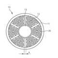
도 2는 도 1에 도시된 하부헤더(10)의 단면 개략도이고, 도 3은 하부헤더(10) 및 중공사막(30)의 일부를 도시한 개략 사시도이다. 도 2 및 3을 참조하면, 다수 개의 구획 분리부재(section divider)(11)들이 하부헤더(10) 내부에 소정의 간격으로 이격되어 배치된다. 구획 분리부재(11)는 3 내지 12개가 방사상으로 형성될 수 있으며, 바람직하게는 도 2에 도시된 바와 같이 6개의 구획 분리부재(11)가 방사상으로 형성될 수 있다. 이 때, 상기 구획 분리부재(11)의 개수가 3개 미만이면 중공사막(30) 다발간의 간격이 충분히 확보되지 못하여 에어에 의한 상향수류의 발생이 제한될 수 있고, 12개를 초과하면 구획 분리부재(11)가 차지하는 부피에 의해 중공사막(30)의 충진밀도가 떨어지거나 구획 분리부재(11)의 부피를 줄이는 경우 중공사막(30) 다발간의 간격이 충분히 확보되지 못하여 내오염성 증대효과가 감소된다.
FIG. 2 is a schematic cross-sectional view of the
본 발명에서 구획 분리부재(11)의 폭(a)은 2 내지 50 mm일 수 있다. 이 때, 상기 구획 분리부재(11)의 폭(a)이 2mm미만이면 구획의 형성이 불완전하여 중공사막(30) 다발이 소정의 간격으로 이격되지 못하고, 50mm를 초과하면 구획 분리부재가 차지하는 부피에 의해 중공사막(30)의 충진밀도가 떨어진다.In the present invention, the width a of the partitioning
상기 구획 분리부재(11)의 높이는 하부헤더(10)의 높이와 동일하거나 1 내지 2cm 정도 작을 수 있다. 또한, 구획 분리부재(11)는 고분자 성형체, 세라믹 또는 금속재질로 형성될 수 있다.
The height of the
이와 같이, 본 발명에 의한 중공사막 모듈(1)은 하부헤더(10)를 일정한 구획으로 구분하는 구획 분리부재(11)를 포함하여 다발 내에서 중공사막(30)이 집속될 수 있어 모듈의 제작 공정이 간단하다. 또한, 중공사막(30) 다발간에 간격이 형성되기 때문에 모듈을 이용한 여과 장치 운전시 모듈 내부로 유입된 에어의 흐름에 의한 상향수류의 발생을 용이하게 할 수 있다. 또한, 에어 및 역세를 통한 세척 공정시 발생하는 고농도의 오염물질 또는 협착물질들이 유동할 수 있는 충분한 공간을 마련해주어 이들이 모듈 외부로 쉽게 배출되도록 한다. 이에 의해, 여과 장치를 장시간 운전하여도 모듈 내측 하단부의 오염물질 퇴적 현상 및 막힘(clogging) 현상을 경감시켜 세척 효율을 증가시킬 수 있다.
As described above, the hollow fiber membrane module 1 according to the present invention includes the
본 발명에서 중공사막(30)은 섬유간의 평균 거리를 0.01 mm 내지 50 mm 로 하는 것이 바람직하나 반드시 이에 제한되는 것은 아니다. 즉, 분리막이 가능한 조밀하게 배열되도록해야 하지만, 이를 만족시키기 위해 막간 간격을 0.01 mm 이하로 지나치게 좁히면 분리막 사이로 원수 및 공기의 유동이 어렵기 때문에 막간 폐색이 유발되기 쉽다. 또한, 50mm 이상으로 막간간격을 넓히면 모듈의 분리막 충진밀도가 떨어져 수처리 능력이 저하된다.
In the present invention, the average distance between the fibers of the
한편, 하부헤더(10)는 소정의 간격으로 이격되어 형성된 산기관 유입홀(12)을 2 내지 10개 포함할 수 있다. 상기 산기관 유입홀(12)은 하부헤더(10) 포팅(potting)면에 뚫린 구멍으로, 재질은 포팅부위를 채우는 포팅접착제에 따라 달라질 수 있다.Meanwhile, the
상기 산기관 유입홀(12)은 도 2에 도시된 바와 같이 6개의 홀이 방사상으로 형성될 수 있으며, 산기관 유입홀(12)에 의해 산기관(미도시)이 하부헤더(10) 하단부에 일체형으로 끼워맞춤될 수 있다. 또한 하부헤더(10)는 침지조의 원수가 유입 또는 유출될 수 있도록 내부에 중심홀(13)을 포함할 수 있으며, 상기 중심홀(13)의 내부직경은 10 mm 내지 100 mm 이다.
2, six holes may be formed radially, and a diffuser (not shown) may be formed at the lower end of the
상기와 같이 구성된 본 발명에 의한 중공사막 모듈을 이용한 여과 장치를 운전함에 있어 외부의 블로워(미도시)에 의해 공기 또는 산소가 하부헤더(10) 하부에 위치한 산기관을 통해 폭기되고, 중공사막(30)에 투과된 처리수는 처리수 이송관(미도시)을 따라 배출된다. 상기 중공사막(30)은 성능이 저하될 경우 역세척 공기 라인(미도시)를 통해 역세척이 가능하다. 또한, 하우징(40) 하부로부터 모듈 길이의 90% 에 해당하는 길이 이내의 외벽을 포함하여 수평 방향으로 확산된 세정 공기가 하우징(40) 외부로 빠져나가는 것을 방지할 수 있다.In operation of the filtration apparatus using the hollow fiber membrane module according to the present invention, air or oxygen is aerated through an air diffuser located below the
이상에서 본 발명의 바람직한 실시예에 대하여 상세하게 설명하였으나, 본 발명은 상술한 실시예에 국한되는 것은 아니고, 본 발명의 취지 또는 범위를 벗어나지 않고 본 발명의 구조를 다양하게 변경하고 변형할 수 있다는 사실은 당업자에게 자명할 것이다. 따라서, 본 발명의 보호범위는 첨부한 특허청구범위 및 그와 균등한 범위로 정해져야 할 것이다.
While the present invention has been particularly shown and described with reference to exemplary embodiments thereof, it is to be understood that the invention is not limited to the disclosed exemplary embodiments, but, on the contrary, The facts will be apparent to those skilled in the art. Accordingly, the scope of protection of the present invention should be defined in the appended claims and their equivalents.
1: 중공사막 모듈 10: 하부헤더
11: 구획 분리부재 12: 산기관 유입홀
13: 하부헤더 중심홀 20: 상부헤더
30: 중공사막 40: 하우징
50: 상부개구부1: Hollow fiber membrane module 10: Lower header
11: compartment separating member 12: diffuser inlet hole
13: lower header center hole 20: upper header
30: hollow fiber membrane 40: housing
50: upper opening
Claims (8)
Translated fromKorean상부헤더와 하부헤더 사이에 배열되는 중공사막; 및
상기 중공사막을 감싸도록 설치되는 하우징; 및
상기 하부헤더 하부에 위치한 산기관을 포함하는 침지형 중공사막 모듈에 있어서, 상기 하부헤더 내부에 상기 중공사막의 다발 간 간격을 형성시키는 다수 개의 구획 분리부재를 포함하고, 상기 하부헤더는 소정의 간격으로 이격되어 형성된 2 내지 10개의 산기관 유입홀을 포함하며, 상기 산기관 유입홀은 상기 하부헤더 포팅(potting)면에 뚫린 구멍으로서, 상기 산기관 유입홀에 의해 상기 산기관이 상기 하부헤더 하단부에 일체형으로 끼워맞춤되는 것을 특징으로 하는 침지형 중공사막 모듈.
Upper header and lower header;
A hollow fiber membrane arranged between the upper header and the lower header; And
A housing installed to surround the hollow fiber membrane; And
Wherein the lower header includes a plurality of partitioning members for forming a space between the bundles of the hollow fiber membranes in the lower header, wherein the lower header is disposed at a predetermined interval Wherein the air diffusing hole is formed in the lower header potting surface so that the air diffusing hole is formed in the bottom header lower end portion Wherein the hollow fiber membrane module is integrally formed.
The submerged hollow fiber membrane module according to claim 1, wherein 3 to 12 divisional members are spaced apart at predetermined intervals.
The submerged hollow fiber membrane module according to claim 1, wherein the partitioning member is radially formed.
The submerged hollow fiber membrane module according to claim 1, wherein the partitioning member has a thickness of 2 to 50 mm.
The submerged hollow fiber membrane module according to claim 1, wherein the partition separating member is formed of a polymer molding, ceramic, or metal.
The submerged hollow fiber membrane module according to claim 1, wherein the lower header includes a central hole having a diameter of 10 to 100 mm inside.
Priority Applications (1)
| Application Number | Priority Date | Filing Date | Title |
|---|---|---|---|
| KR1020120110801AKR101515685B1 (en) | 2012-10-05 | 2012-10-05 | Membrane module comprising section divider for reducing membrane fouling |
Applications Claiming Priority (1)
| Application Number | Priority Date | Filing Date | Title |
|---|---|---|---|
| KR1020120110801AKR101515685B1 (en) | 2012-10-05 | 2012-10-05 | Membrane module comprising section divider for reducing membrane fouling |
Publications (2)
| Publication Number | Publication Date |
|---|---|
| KR20140044616A KR20140044616A (en) | 2014-04-15 |
| KR101515685B1true KR101515685B1 (en) | 2015-04-27 |
Family
ID=50652540
Family Applications (1)
| Application Number | Title | Priority Date | Filing Date |
|---|---|---|---|
| KR1020120110801AActiveKR101515685B1 (en) | 2012-10-05 | 2012-10-05 | Membrane module comprising section divider for reducing membrane fouling |
Country Status (1)
| Country | Link |
|---|---|
| KR (1) | KR101515685B1 (en) |
Families Citing this family (1)
| Publication number | Priority date | Publication date | Assignee | Title |
|---|---|---|---|---|
| CN115779691B (en)* | 2022-12-16 | 2025-10-03 | 山东招金膜天股份有限公司 | Adjustable partition water distribution rack for hollow fiber column membrane modules |
Citations (2)
| Publication number | Priority date | Publication date | Assignee | Title |
|---|---|---|---|---|
| JP2004344851A (en)* | 2003-05-26 | 2004-12-09 | Toyobo Co Ltd | Membrane filtration module |
| JP2006116495A (en)* | 2004-10-25 | 2006-05-11 | Sumitomo Electric Fine Polymer Inc | Filter device |
- 2012
- 2012-10-05KRKR1020120110801Apatent/KR101515685B1/enactiveActive
Patent Citations (2)
| Publication number | Priority date | Publication date | Assignee | Title |
|---|---|---|---|---|
| JP2004344851A (en)* | 2003-05-26 | 2004-12-09 | Toyobo Co Ltd | Membrane filtration module |
| JP2006116495A (en)* | 2004-10-25 | 2006-05-11 | Sumitomo Electric Fine Polymer Inc | Filter device |
Also Published As
| Publication number | Publication date |
|---|---|
| KR20140044616A (en) | 2014-04-15 |
Similar Documents
| Publication | Publication Date | Title |
|---|---|---|
| US7491329B2 (en) | Hollow fiber membrane module, hollow fiber membrane module unit, membrane filtration device using the same and method of operating the same | |
| KR100974912B1 (en) | Piping integrated membrane frame structure and membrane unit using same | |
| WO2001000307A2 (en) | Self cleaning filter | |
| WO2006080482A1 (en) | Method for manufacturing module having selectively permeable membrane and module having selectively permeable membrane | |
| CN103442789A (en) | Filtration device and hollow-fiber membrane module | |
| CA2778102C (en) | Flat membrane module with stepped flow guide | |
| KR20130082363A (en) | Membrane module using hallow fiber | |
| WO2007083723A1 (en) | Membrane filtration apparatus and its operating method | |
| JP2016068046A (en) | Vertically-arranged external pressure type hollow fiber membrane module and method of operating the same | |
| WO2014192433A1 (en) | Filtration device and immersed filtration method using same | |
| KR101402399B1 (en) | Lower water collecting assembly of pressured membrane module water-purifying apparatus | |
| KR20130035415A (en) | Aeration unit and filtering apparatus comprising the same | |
| KR101515685B1 (en) | Membrane module comprising section divider for reducing membrane fouling | |
| KR100626173B1 (en) | Hollow fiber membrane module and water treatment device using the same | |
| KR20100092227A (en) | Hollow fiber membrane module and filtering system comprising the same | |
| KR101685356B1 (en) | Vertical Type Hollow Fiber Membrane Module and Filtering System Using The Same | |
| KR101889109B1 (en) | Apparatus of spiral aerator and hollow fiber membrane module including the same | |
| KR101130497B1 (en) | Submerged Flat Membrane Module For Water Treatment | |
| KR100340450B1 (en) | Membrane for Water Treatment Using Hollow Fiber | |
| JP2007152302A (en) | Solid-liquid separation device for solid-liquid mixed processing liquid | |
| JP6910850B2 (en) | An air diffuser, a hollow fiber membrane module including the air diffuser, and a water treatment method. | |
| JP2010119948A (en) | Membrane separator, and filtration treatment operation method | |
| KR102336809B1 (en) | Filtering apparatus of submerged type | |
| KR101417292B1 (en) | Membrane module equipped with all-in-one air diffuser and ultrasonic generator | |
| KR101288003B1 (en) | Apparatus of waste water treatment using membrane module |
Legal Events
| Date | Code | Title | Description |
|---|---|---|---|
| A201 | Request for examination | ||
| PA0109 | Patent application | Patent event code:PA01091R01D Comment text:Patent Application Patent event date:20121005 | |
| PA0201 | Request for examination | ||
| E902 | Notification of reason for refusal | ||
| PE0902 | Notice of grounds for rejection | Comment text:Notification of reason for refusal Patent event date:20131231 Patent event code:PE09021S01D | |
| PG1501 | Laying open of application | ||
| E90F | Notification of reason for final refusal | ||
| PE0902 | Notice of grounds for rejection | Comment text:Final Notice of Reason for Refusal Patent event date:20140725 Patent event code:PE09021S02D | |
| E701 | Decision to grant or registration of patent right | ||
| PE0701 | Decision of registration | Patent event code:PE07011S01D Comment text:Decision to Grant Registration Patent event date:20150126 | |
| GRNT | Written decision to grant | ||
| PR0701 | Registration of establishment | Comment text:Registration of Establishment Patent event date:20150421 Patent event code:PR07011E01D | |
| PR1002 | Payment of registration fee | Payment date:20150421 End annual number:3 Start annual number:1 | |
| PG1601 | Publication of registration | ||
| FPAY | Annual fee payment | Payment date:20180312 Year of fee payment:4 | |
| PR1001 | Payment of annual fee | Payment date:20180312 Start annual number:4 End annual number:4 | |
| FPAY | Annual fee payment | Payment date:20190312 Year of fee payment:5 | |
| PR1001 | Payment of annual fee | Payment date:20190312 Start annual number:5 End annual number:5 | |
| FPAY | Annual fee payment | Payment date:20200311 Year of fee payment:6 | |
| PR1001 | Payment of annual fee | Payment date:20200311 Start annual number:6 End annual number:6 | |
| PR1001 | Payment of annual fee | Payment date:20210310 Start annual number:7 End annual number:7 | |
| PR1001 | Payment of annual fee | Payment date:20220310 Start annual number:8 End annual number:8 | |
| PR1001 | Payment of annual fee | Payment date:20230313 Start annual number:9 End annual number:9 | |
| PR1001 | Payment of annual fee | Payment date:20240312 Start annual number:10 End annual number:10 | |
| PR1001 | Payment of annual fee | Payment date:20250312 Start annual number:11 End annual number:11 |