KR101514915B1 - Male member - Google Patents
Male memberDownload PDFInfo
- Publication number
- KR101514915B1 KR101514915B1KR1020137034969AKR20137034969AKR101514915B1KR 101514915 B1KR101514915 B1KR 101514915B1KR 1020137034969 AKR1020137034969 AKR 1020137034969AKR 20137034969 AKR20137034969 AKR 20137034969AKR 101514915 B1KR101514915 B1KR 101514915B1
- Authority
- KR
- South Korea
- Prior art keywords
- tubular member
- cover
- lumen
- slit
- outer peripheral
- Prior art date
- Legal status (The legal status is an assumption and is not a legal conclusion. Google has not performed a legal analysis and makes no representation as to the accuracy of the status listed.)
- Active
Links
- 230000002093peripheral effectEffects0.000claimsabstractdescription43
- XLYOFNOQVPJJNP-UHFFFAOYSA-NwaterSubstancesOXLYOFNOQVPJJNP-UHFFFAOYSA-N0.000claimsabstractdescription40
- 239000011344liquid materialSubstances0.000claimsdescription32
- 238000000034methodMethods0.000claimsdescription18
- 230000000149penetrating effectEffects0.000claimsdescription4
- 238000000926separation methodMethods0.000abstractdescription5
- 239000007791liquid phaseSubstances0.000abstractdescription2
- 239000007788liquidSubstances0.000description19
- 239000003814drugSubstances0.000description5
- 229940079593drugDrugs0.000description4
- 229920001971elastomerPolymers0.000description4
- 239000008280bloodSubstances0.000description3
- 210000004369bloodAnatomy0.000description3
- 239000013013elastic materialSubstances0.000description3
- 239000000463materialSubstances0.000description3
- 241000894006BacteriaSpecies0.000description2
- 239000002246antineoplastic agentSubstances0.000description2
- 229940041181antineoplastic drugDrugs0.000description2
- 230000017531blood circulationEffects0.000description2
- 239000000470constituentSubstances0.000description2
- 230000007423decreaseEffects0.000description2
- 238000005192partitionMethods0.000description2
- 241000251468ActinopterygiiSpecies0.000description1
- 229930182556PolyacetalNatural products0.000description1
- 238000013459approachMethods0.000description1
- 238000004891communicationMethods0.000description1
- 238000001704evaporationMethods0.000description1
- 230000008020evaporationEffects0.000description1
- 235000013305foodNutrition0.000description1
- 230000004927fusionEffects0.000description1
- 231100001261hazardousToxicity0.000description1
- 238000002347injectionMethods0.000description1
- 239000007924injectionSubstances0.000description1
- 229920003049isoprene rubberPolymers0.000description1
- 239000004973liquid crystal related substanceSubstances0.000description1
- 230000007246mechanismEffects0.000description1
- 239000002184metalSubstances0.000description1
- 238000000465mouldingMethods0.000description1
- 229920000515polycarbonatePolymers0.000description1
- 239000004417polycarbonateSubstances0.000description1
- 229920006324polyoxymethylenePolymers0.000description1
- 238000002360preparation methodMethods0.000description1
- 238000011084recoveryMethods0.000description1
- 239000011347resinSubstances0.000description1
- 229920005989resinPolymers0.000description1
- 229920002379silicone rubberPolymers0.000description1
- 239000004945silicone rubberSubstances0.000description1
- 239000000243solutionSubstances0.000description1
- 239000000126substanceSubstances0.000description1
- 238000001356surgical procedureMethods0.000description1
Images


Classifications
- A—HUMAN NECESSITIES
- A61—MEDICAL OR VETERINARY SCIENCE; HYGIENE
- A61M—DEVICES FOR INTRODUCING MEDIA INTO, OR ONTO, THE BODY; DEVICES FOR TRANSDUCING BODY MEDIA OR FOR TAKING MEDIA FROM THE BODY; DEVICES FOR PRODUCING OR ENDING SLEEP OR STUPOR
- A61M39/00—Tubes, tube connectors, tube couplings, valves, access sites or the like, specially adapted for medical use
- A61M39/10—Tube connectors; Tube couplings
- A—HUMAN NECESSITIES
- A61—MEDICAL OR VETERINARY SCIENCE; HYGIENE
- A61M—DEVICES FOR INTRODUCING MEDIA INTO, OR ONTO, THE BODY; DEVICES FOR TRANSDUCING BODY MEDIA OR FOR TAKING MEDIA FROM THE BODY; DEVICES FOR PRODUCING OR ENDING SLEEP OR STUPOR
- A61M39/00—Tubes, tube connectors, tube couplings, valves, access sites or the like, specially adapted for medical use
- A61M39/02—Access sites
- A—HUMAN NECESSITIES
- A61—MEDICAL OR VETERINARY SCIENCE; HYGIENE
- A61J—CONTAINERS SPECIALLY ADAPTED FOR MEDICAL OR PHARMACEUTICAL PURPOSES; DEVICES OR METHODS SPECIALLY ADAPTED FOR BRINGING PHARMACEUTICAL PRODUCTS INTO PARTICULAR PHYSICAL OR ADMINISTERING FORMS; DEVICES FOR ADMINISTERING FOOD OR MEDICINES ORALLY; BABY COMFORTERS; DEVICES FOR RECEIVING SPITTLE
- A61J1/00—Containers specially adapted for medical or pharmaceutical purposes
- A61J1/14—Details; Accessories therefor
- F—MECHANICAL ENGINEERING; LIGHTING; HEATING; WEAPONS; BLASTING
- F16—ENGINEERING ELEMENTS AND UNITS; GENERAL MEASURES FOR PRODUCING AND MAINTAINING EFFECTIVE FUNCTIONING OF MACHINES OR INSTALLATIONS; THERMAL INSULATION IN GENERAL
- F16L—PIPES; JOINTS OR FITTINGS FOR PIPES; SUPPORTS FOR PIPES, CABLES OR PROTECTIVE TUBING; MEANS FOR THERMAL INSULATION IN GENERAL
- F16L37/00—Couplings of the quick-acting type
- F16L37/28—Couplings of the quick-acting type with fluid cut-off means
- F16L37/30—Couplings of the quick-acting type with fluid cut-off means with fluid cut-off means in each of two pipe-end fittings
- A—HUMAN NECESSITIES
- A61—MEDICAL OR VETERINARY SCIENCE; HYGIENE
- A61M—DEVICES FOR INTRODUCING MEDIA INTO, OR ONTO, THE BODY; DEVICES FOR TRANSDUCING BODY MEDIA OR FOR TAKING MEDIA FROM THE BODY; DEVICES FOR PRODUCING OR ENDING SLEEP OR STUPOR
- A61M39/00—Tubes, tube connectors, tube couplings, valves, access sites or the like, specially adapted for medical use
- A61M39/10—Tube connectors; Tube couplings
- A61M2039/1027—Quick-acting type connectors
- A—HUMAN NECESSITIES
- A61—MEDICAL OR VETERINARY SCIENCE; HYGIENE
- A61M—DEVICES FOR INTRODUCING MEDIA INTO, OR ONTO, THE BODY; DEVICES FOR TRANSDUCING BODY MEDIA OR FOR TAKING MEDIA FROM THE BODY; DEVICES FOR PRODUCING OR ENDING SLEEP OR STUPOR
- A61M39/00—Tubes, tube connectors, tube couplings, valves, access sites or the like, specially adapted for medical use
- A61M39/10—Tube connectors; Tube couplings
- A61M2039/1066—Tube connectors; Tube couplings having protection means, e.g. sliding sleeve to protect connector itself, shrouds to protect a needle present in the connector, protective housing, isolating sheath
- A—HUMAN NECESSITIES
- A61—MEDICAL OR VETERINARY SCIENCE; HYGIENE
- A61M—DEVICES FOR INTRODUCING MEDIA INTO, OR ONTO, THE BODY; DEVICES FOR TRANSDUCING BODY MEDIA OR FOR TAKING MEDIA FROM THE BODY; DEVICES FOR PRODUCING OR ENDING SLEEP OR STUPOR
- A61M39/00—Tubes, tube connectors, tube couplings, valves, access sites or the like, specially adapted for medical use
- A61M39/22—Valves or arrangement of valves
- A61M39/24—Check- or non-return valves
- A61M2039/2433—Valve comprising a resilient or deformable element, e.g. flap valve, deformable disc
- A—HUMAN NECESSITIES
- A61—MEDICAL OR VETERINARY SCIENCE; HYGIENE
- A61M—DEVICES FOR INTRODUCING MEDIA INTO, OR ONTO, THE BODY; DEVICES FOR TRANSDUCING BODY MEDIA OR FOR TAKING MEDIA FROM THE BODY; DEVICES FOR PRODUCING OR ENDING SLEEP OR STUPOR
- A61M39/00—Tubes, tube connectors, tube couplings, valves, access sites or the like, specially adapted for medical use
- A61M39/22—Valves or arrangement of valves
- A61M39/24—Check- or non-return valves
- A61M2039/2473—Valve comprising a non-deformable, movable element, e.g. ball-valve, valve with movable stopper or reciprocating element
- Y—GENERAL TAGGING OF NEW TECHNOLOGICAL DEVELOPMENTS; GENERAL TAGGING OF CROSS-SECTIONAL TECHNOLOGIES SPANNING OVER SEVERAL SECTIONS OF THE IPC; TECHNICAL SUBJECTS COVERED BY FORMER USPC CROSS-REFERENCE ART COLLECTIONS [XRACs] AND DIGESTS
- Y10—TECHNICAL SUBJECTS COVERED BY FORMER USPC
- Y10S—TECHNICAL SUBJECTS COVERED BY FORMER USPC CROSS-REFERENCE ART COLLECTIONS [XRACs] AND DIGESTS
- Y10S604/00—Surgery
- Y10S604/905—Aseptic connectors or couplings, e.g. frangible, piercable
Landscapes
- Health & Medical Sciences (AREA)
- Engineering & Computer Science (AREA)
- Heart & Thoracic Surgery (AREA)
- General Engineering & Computer Science (AREA)
- Life Sciences & Earth Sciences (AREA)
- Animal Behavior & Ethology (AREA)
- General Health & Medical Sciences (AREA)
- Public Health (AREA)
- Veterinary Medicine (AREA)
- Pulmonology (AREA)
- Anesthesiology (AREA)
- Biomedical Technology (AREA)
- Hematology (AREA)
- Mechanical Engineering (AREA)
- Pharmacology & Pharmacy (AREA)
- Infusion, Injection, And Reservoir Apparatuses (AREA)
- Medical Preparation Storing Or Oral Administration Devices (AREA)
- Closures For Containers (AREA)
Abstract
Translated fromKoreanDescription
Translated fromKorean본 발명은, 액상물이 흐르는 유로가 형성된 관상 부재와, 상기 관상 부재의 선단을 적어도 덮는 커버를 구비한 수부재에 관한 것이다.The present invention relates to a water member provided with a tubular member having a flow path through which a liquid material flows and a cover at least covering a tip end of the tubular member.
환자에게 수액이나 수혈을 행하거나, 수술에 있어서 체외 혈액 순환을 행하는 경우에, 약액이나 혈액 등의 액상물을 수송하기 위한 경로(수송 라인)를 형성할 필요가 있다. 수송 라인은, 일반적으로 용기나 각종 기구, 튜브 등을 접속함으로써 형성된다. 상이한 부재를 접속하는 방법으로서, 수부재로서의 수루어와 암부재로서의 니들레스 포트(needle-less port)의 슬립 접속이 알려져 있다(예를 들어 특허 문헌 1, 2 참조). 니들레스 포트는, 중앙부에 직선상의 슬릿(절입)이 형성된 고무 등의 탄성 재료로 이루어지는 격벽 부재(이하 「셉텀」이라고 한다)를 구비한다. 셉텀의 슬릿에, 주사 바늘 등의 예리한 금속 바늘이 붙어 있지 않은 수루어(관상체)를 삽입함으로써, 니들레스 포트와 수루어를 연통시킬 수 있다. 니들레스 포트로부터 수루어를 뽑아내면 셉텀의 슬릿은 즉시 닫힌다. 이와 같이, 셉텀은 재실링성을 가져, 수루어를 반복하여 빼고 꽂을 수 있다.It is necessary to form a path (transport line) for transporting a liquid substance such as a drug solution or blood when the patient performs transfusion or blood transfusion or extracorporeal blood circulation in surgery. The transport line is generally formed by connecting a container, various mechanisms, tubes, or the like. As a method of connecting different members, a slip connection of a needle-less port as a female member and a female member as a male member is known (see, for example,
상기 서술의 슬립 접속에서는, 니들레스 포트로부터 수루어를 뽑아내면, 셉텀의 슬릿은 즉시 닫히므로, 수루어가 접속되어 있지 않은 니들레스 포트로부터 액상물이 빠져나올 가능성은 일반적으로 낮다. 그러나, 니들레스 포트에 삽입하기 전 및 뽑아낸 후의 수루어는, 외계에 노출되어 있기 때문에, 수루어로부터 액상물이 빠져나올 가능성이 있다.In the above-described slip connection, when the male thread is pulled out from the needleless port, the slit of the septum is immediately closed, so that the possibility of the liquid matter escaping from the needleless port to which the male thread is not connected is generally low. However, since the water lures before and after being inserted into the needlesport are exposed to the outside world, there is a possibility that the liquid water escapes from the water lures.
니들레스 포트에 접속되어 있지 않은 수루어로부터 액상물이 빠져나올 가능성을 저감하기 위해, 도 7에 도시하는 바와 같이, 수루어(110)를 신축 가능한 커버(120)로 덮는 방법이 알려져 있다(특허 문헌 3, 4를 참조). 커버(120)는, 대략 통형상을 가지는 외주벽(121)을 구비하고, 외주벽(121)의 일단은 천판(123)으로 막혀 있다. 수루어(110)는 통형상을 가지고, 그 선단에는 액상물이 유출입하는 개구(112)가 형성되어 있다. 수루어(110)의 개구(112)가 대향하는 천판(123)의 위치에는 직선상의 슬릿(절입)(125)이 형성되어 있다. 니들레스 포트(150)의 셉텀(151)은, 고무 등의 탄성 재료로 이루어지는 원판상 부재이며, 그 중앙에는 직선상의 슬릿(절입)(152)이 형성되어 있다. 셉텀(151)은, 대략 원통형상을 가지는 기체부(153)와 포트 캡(155)에 의해 협지되어 고정되어 있다.A method is known in which the
도 7에 도시하는 바와 같이, 수루어(110)가 니들레스 포트(150)에 접속되어 있지 않을 때에는, 수루어(110)의 개구(112)는 커버(120)의 천판(123)이 밀착함으로써 막혀 있다. 커버(120)의 슬릿(125)은 닫혀 있다. 이 상태로부터 수루어(110)를 니들레스 포트(150)에 밀어넣으면, 수루어(110)가 커버(120)의 슬릿(125)을 관통하고, 더욱 셉텀(151)의 슬릿(152)을 관통하며, 수루어(110)와 니들레스 포트(150)를 접속할 수 있다. 이 때, 커버(120)의 외주벽(121)은 압축 변형한다. 그 후, 수루어(110)를 니들레스 포트(150)로부터 뽑아내면, 커버(120)의 외주벽(121)이 그 탄성 회복력에 의해 신장하여, 초기 상태로 돌아온다.7, when the
이상과 같이 수루어(110)에 커버(120)를 씌움으로써, 도 7과 같이 수루어(110)가 니들레스 포트(150)에 접속되어 있지 않은 상태일 때에, 수루어(110)의 개구(112)를 커버(120)의 천판(123)으로 막을 수 있다. 따라서, 수루어(110)로부터 액상물이 빠져나올 가능성은 낮다.When the
그런데, 도 7의 구성에서는, 니들레스 포트(150)로부터 수루어(110)를 뽑아내면, 커버(120)의 천판(123)의 외표면(123a) 및 셉텀(151)의 외표면(151a)에 액상물이 잔존한다고 하는 문제가 있다.7, the
커버(120)의 천판(123)의 외표면(123a)이나 셉텀(151)의 외표면(151a)에 잔존한 액상물 중에서 예를 들어 세균이 번식하면, 그 후, 수루어(110)를 니들레스 포트(150)에 재접속했을 때에, 액상물의 수송 경로 내에 세균이 혼입할 가능성이 있다.If the bacteria in the liquid material remaining on the
또, 액상물이 예를 들어 일부의 항암제와 같은 극약으로 지정된 약제를 포함하는 경우, 이러한 액상물이 커버(120)의 천판(123)의 외표면(123a)이나 셉텀(151)의 외표면(151a)에 잔존하면, 액상물이 작업자의 손가락 등에 부착하거나 액상물의 증기를 작업자가 흡인할 가능성이 있다.When the liquid material includes a medicine designated by a drug, such as some anticancer drugs, the liquid material may adhere to the
본 발명의 목적은, 암부재에 대해 비접속 상태일 때에 액상물의 누출을 방지하는 커버를 구비한 수부재에 있어서, 암부재로부터 분리한 후에 커버 및 암부재의 외표면에 부착하는 액상물량을 줄이는 것에 있다.An object of the present invention is to provide a male member having a cover for preventing the leakage of liquid matter when the male member is in a non-connected state with respect to the female member, wherein the amount of liquid adhered to the outer surface of the cover and the female member after separation from the female member is reduced It is on.
본 발명의 수부재는, 액상물이 흐르는 유로가 형성된 관상 부재와, 상기 관상 부재의 선단을 적어도 덮는 커버를 구비한다. 상기 관상 부재의 외주면에, 상기 유로와 연통한 횡공이 형성되어 있다. 상기 커버는, 탄성적으로 압축 변형 가능한 외주벽과, 상기 외주벽의 일단에 설치된 머리부를 구비한다. 상기 머리부에는, 상기 관상 부재의 상기 선단이 삽입되는 내강이 형성되어 있다. 상기 내강의 최심부에는, 상기 머리부를 관통하는 슬릿이 형성되어 있다. 상기 외주벽이 압축 변형되어 있지 않은 상태에 있어서, 상기 머리부의 상기 내강의 내주면이 상기 관상 부재의 상기 외주면과 밀착하여 상기 횡공을 막고, 또한, 상기 관상 부재의 선단과 상기 내강의 상기 최심부가 이격되어 있다. 상기 외주벽이 압축 변형하도록 상기 관상 부재에 대해 상기 머리부를 변위시키면, 상기 관상 부재가 상기 슬릿을 관통하고, 상기 횡공이 상기 머리부로부터 노출한다.The water member of the present invention comprises a tubular member having a flow path through which a liquid material flows, and a cover at least covering the front end of the tubular member. And a transverse hole communicating with the flow path is formed on the outer peripheral surface of the tubular member. The cover includes an outer peripheral wall which is resiliently compressible and deformable, and a head portion provided at one end of the outer peripheral wall. The head portion is formed with a lumen into which the tip end of the tubular member is inserted. A slit penetrating through the head portion is formed in the deepest portion of the lumen. Wherein an inner circumferential surface of the lumen of the head portion is in close contact with the outer circumferential surface of the tubular member so as to close the transverse hole while the outer circumferential wall is not compressively deformed, and the distal end of the tubular member and the distal- . When the head portion is displaced with respect to the tubular member such that the outer peripheral wall is compressively deformed, the tubular member passes through the slit, and the transverse hole is exposed from the head portion.
본 발명에 의하면, 커버의 외주벽이 압축 변형되어 있지 않은 상태에 있어서, 머리부의 내강의 내주면이 관상 부재의 횡공을 막고 있으므로, 수부재를 암부재에 대해 접속하고 있지 않은 상태일 때에, 수부재로부터 액상물이 빠져나오는 것을 방지할 수 있다.According to the present invention, in the state in which the outer peripheral wall of the cover is not compressively deformed, the inner peripheral surface of the lumen of the head portion blocks the horizontal holes of the tubular member, It is possible to prevent the liquid material from escaping from the discharge port.
또, 커버의 외주벽이 압축 변형되어 있지 않은 상태에 있어서, 관상 부재의 선단과, 슬릿이 형성된 내강의 최심부가 이격되어 있다. 따라서, 수부재를 암부재로부터 분리하는 과정에서 관상 부재의 선단과 내강의 최심부의 사이에 형성되는 간극 내에 그 용적의 확대에 따른 부압을 발생시킬 수 있다. 이 부압에 의해, 커버와 암부재의 사이에 잔존하는 액상물이 간극 내로 흡인된다. 그 결과, 수부재와 암부재를 분리한 후에 커버 및 암부재의 외표면에 부착하는 액상물량을 줄일 수 있다.In the state where the outer peripheral wall of the cover is not compressively deformed, the distal end of the tubular member and the deepest portion of the lumen formed with the slit are spaced apart. Accordingly, in the process of separating the male member from the female member, a negative pressure due to the enlargement of the volume can be generated in the gap formed between the tip of the tubular member and the deepest portion of the lumen. By this negative pressure, the liquid matter remaining between the cover and the arm member is sucked into the gap. As a result, after separating the male member and the female member, the amount of the liquid adhering to the outer surface of the cover and the female member can be reduced.
도 1은, 본 발명의 일실시 형태에 따른 수부재의 개략 구성을 도시한 단면도이다.
도 2A는, 본 발명의 일실시 형태에 따른 수부재를 구성하는 커버의 상방에서 본 사시도, 도 2B는 그 하방에서 본 사시도이다.
도 3A는, 본 발명의 일실시 형태에 따른 수부재를 구성하는 커버의 상면도, 도 3B는 그 측면도, 도 3C는 상하 방향을 따르는 그 단면도이다.
도 4A는, 접속 전의 본 발명의 일실시 형태에 따른 수부재 및 니들레스 포트의 단면도이다.
도 4B는, 접속 도중의 본 발명의 일실시 형태에 따른 수부재 및 니들레스 포트의 단면도이다.
도 4C는, 접속 완료시의 본 발명의 일실시 형태에 따른 수부재 및 니들레스 포트의 단면도이다.
도 5A는, 분리 도중의 본 발명의 일실시 형태에 따른 수부재 및 니들레스 포트의 단면도이다.
도 5B는, 분리 도중의 본 발명의 일실시 형태에 따른 수부재 및 니들레스 포트의 단면도이다.
도 6은, 본 발명의 다른 실시 형태에 따른 수부재를 구성하는 커버의, 상하 방향을 따르는 단면도이다.
도 7은, 니들레스 포트에 접속되는 종래의 커버 장착 수루어를 도시한 단면도이다.
도 8A~도 8D는, 종래의 커버 장착 수루어가 니들레스 포트에 삽입되는 모습을 차례로 도시한 단면도이다.1 is a cross-sectional view showing a schematic structure of a male member according to an embodiment of the present invention.
Fig. 2A is a perspective view of a cover constituting a male member according to an embodiment of the present invention as seen from above, and Fig. 2B is a perspective view as viewed from below.
FIG. 3A is a top view of a cover constituting a male member according to an embodiment of the present invention, FIG. 3B is a side view thereof, and FIG. 3C is a sectional view thereof along a vertical direction.
4A is a cross-sectional view of a water member and a needleless port according to an embodiment of the present invention before connection.
4B is a cross-sectional view of the male member and the needleless port according to one embodiment of the present invention during connection;
4C is a cross-sectional view of a male member and a needleless port according to an embodiment of the present invention at the time of completion of connection.
5A is a cross-sectional view of a water member and a needleless port according to one embodiment of the present invention during separation.
5B is a cross-sectional view of a water member and a needleless port according to an embodiment of the present invention during separation.
6 is a cross-sectional view of a cover constituting a male member according to another embodiment of the present invention, taken along the vertical direction.
7 is a cross-sectional view showing a conventional cover mount water louer connected to a needleless port.
8A to 8D are sectional views sequentially showing a state in which a conventional cover mount water lure is inserted into a needleless port.
본 발명자들은, 도 7에 도시한 종래의 커버(120) 부착의 수루어(110)를 이용한 경우에, 니들레스 포트(150)로부터 수루어(110)를 뽑아낸 후에, 커버(120)의 천판(123)의 외표면(123a) 및 셉텀(151)의 외표면(151a)에 액상물이 잔존하는 원인을 구명하기 위해, 니들레스 포트(150)에 대한 수루어(110)의 접속에서부터 분리까지의 셉텀(151) 및 커버(120)의 변형의 모습을 X선 CT를 이용하여 관찰했다. 이하에 이것을 설명한다.The inventors of the present invention have found that when the
도 8A~도 8D는, 종래의 커버(120) 부착 수루어(110)가 니들레스 포트(150)에 삽입되는 모습을 차례로 도시한 단면도이다. 셉텀(151)에 형성된 슬릿(152) 및 커버(120)의 천판(123)에 형성된 슬릿(125)은, 이들 도의 단면과 수직인 방향을 따라 형성되어 있다.8A to 8D are cross-sectional views sequentially showing a state in which a
도 8A는, 수루어(110)와 니들레스 포트(150)의 접속 직전의 상태를 도시하고 있다. 수루어(110)에 장착된 커버(120)의 천판(123)이, 니들레스 포트(150)의 포트 캡(155)에 접촉하고 있다. 이 상태로부터, 수루어(110)를 니들레스 포트(150)에 밀어넣는다.8A shows a state immediately before the connection of the
도 8B는, 수루어(110)에 의해 커버(120)의 천판(123)이 셉텀(151)을 향해 약간 변형되어 있는 상태를 도시하고 있다. 변형된 천판(123)에 의해 셉텀(151)도 약간 변형되어 있다. 천판(123)과 셉텀(151)의 사이에, 작은 간극(137)이 형성되어 있다. 천판(123)의 슬릿(125) 및 셉텀(151)의 슬릿(152)은 아직 열려있지는 않다.8B shows a state in which the
수루어(110)를 니들레스 포트(150)에 더 밀어넣으면, 도 8C에 도시하는 바와 같이, 커버(120)의 천판(123)의 슬릿(125)이 열린다. 수루어(110)에 의해 천판(123)이 늘어나 포트 캡(155)의 개구 내에 침입하고 있다. 이에 의해, 셉텀(151)도 변형되고, 간극(137)이 확대되어 있다. 단, 셉텀(151)의 슬릿(152)은 아직 열려있지는 않다.The
도 8D는, 수루어(110)와 니들레스 포트(150)의 접속이 완료한 상태를 도시한다. 천판(123)의 변형량이 더 커지고, 수루어(110)가 천판(123)의 슬릿(125)을 관통하고 있다. 수루어(110)의 선단이 셉텀(151)의 외표면(151a)을 가압하여, 그 결과, 셉텀(151)이 크게 구부러지거나 또는 늘어나, 슬릿(152)이 열리고 있다. 이렇게 하여, 수루어(110)와 니들레스 포트(150)가 연통한다.8D shows a state in which the connection between the
그 후, 수루어(110) 및 니들레스 포트(150) 사이에 액상물이 흐른다. 셉텀(151)의 외표면(151a)은 액상물이 흐르는 유로벽의 일부를 구성한다.Thereafter, the liquid material flows between the
다음에, 도 8D의 상태로부터, 수루어(110)를 니들레스 포트(150)로부터 뽑아낸다. 뽑아내기에 앞서, 수루어(110) 및 니들레스 포트(150) 사이의 액상물의 흐름이 정지된다. 액상물의 흐름이 정지한 후에도, 통상, 액상물은 수루어(110) 및 니들레스 포트(150) 내를 충만하고 있다. 니들레스 포트(150)로부터 수루어(110)의 뽑아내기는, 도 8D 내지 도 8A에 상기한 것과는 역으로 진행된다.Next, from the state of Fig. 8D, the
도 8D의 상태로부터 니들레스 포트(150)에 대해 수루어(110)를 후퇴시키면, 도 8C의 상태에서 셉텀(151)의 슬릿(152)이 닫히고, 이어서, 도 8B의 상태에서 천판(123)의 슬릿(125)이 닫힌다. 따라서, 도 8D에 있어서 셉텀(151)의 외표면(151a) 근방에 위치하는 액상물은, 간극(137) 내에 갇힌다. 그 후 수루어(110)를 니들레스 포트(150)로부터 뽑아내고, 커버(120)와 셉텀(151)이 분리하면, 간극(137) 내의 액상물이, 상기 서술한 바와 같이 커버(120)의 천판(123)의 외표면(123a) 및 셉텀(151)의 외표면(151a)에 잔존한다.8C, the
본 발명자들은, 상기의 지견에 의거하여 관상 부재(예를 들어 수루어) 및 그 선단을 적어도 덮는 커버의 형상을 고안함으로써, 관상 부재를 암부재(예를 들어 니들레스 포트)로부터 분리한 후에, 커버 및 암부재의 외표면에 부착하는 액상물량을 줄일 수 있는 것을 찾아내어, 본 발명을 완성했다.The present inventors have devised a shape of a cover that covers at least a tubular member (for example, a water luer) and a tip end of the tubular member based on the above-described knowledge, and after separating the tubular member from the arm member (for example, a needleless port) And that the amount of the liquid adhering to the outer surface of the cover and the arm member can be reduced, thereby completing the present invention.
즉, 본 발명의 수부재는, 액상물이 흐르는 유로가 형성된 관상 부재와, 상기 관상 부재의 선단을 적어도 덮는 커버를 구비한다. 상기 관상 부재의 외주면에, 상기 유로와 연통한 횡공이 형성되어 있다. 상기 커버는, 탄성적으로 압축 변형 가능한 외주벽과, 상기 외주벽의 일단에 설치된 머리부를 구비한다. 상기 머리부에는, 상기 관상 부재의 상기 선단이 삽입되는 내강이 형성되어 있다. 상기 내강의 최심부에는, 상기 머리부를 관통하는 슬릿이 형성되어 있다. 상기 외주벽이 압축 변형되어 있지 않은 상태에 있어서, 상기 머리부의 상기 내강의 내주면이 상기 관상 부재의 상기 외주면과 밀착하여 상기 횡공을 막고, 또한, 상기 관상 부재의 선단과 상기 내강의 상기 최심부가 이격되어 있다. 상기 외주벽이 압축 변형하도록 상기 관상 부재에 대해 상기 머리부를 변위시키면, 상기 관상 부재가 상기 슬릿을 관통하고, 상기 횡공이 상기 머리부로부터 노출한다.That is, the water member of the present invention includes a tubular member having a flow path through which the liquid material flows, and a cover at least covering the front end of the tubular member. And a transverse hole communicating with the flow path is formed on the outer peripheral surface of the tubular member. The cover includes an outer peripheral wall which is resiliently compressible and deformable, and a head portion provided at one end of the outer peripheral wall. The head portion is formed with a lumen into which the tip end of the tubular member is inserted. A slit penetrating through the head portion is formed in the deepest portion of the lumen. Wherein an inner circumferential surface of the lumen of the head portion is in close contact with the outer circumferential surface of the tubular member so as to close the transverse hole while the outer circumferential wall is not compressively deformed, and the distal end of the tubular member and the distal- . When the head portion is displaced with respect to the tubular member such that the outer peripheral wall is compressively deformed, the tubular member passes through the slit, and the transverse hole is exposed from the head portion.
상기 머리부의 선단에 돌출한 꼭대기부가 형성되어 있고, 상기 슬릿은 상기 꼭대기부에 형성되어 있는 것이 바람직하다. 이에 의해, 수부재와 암부재를 분리한 후에 커버 및 암부재의 외표면에 부착하는 액상물량을 더 줄일 수 있다.It is preferable that a top portion protruding from the tip of the head portion is formed, and that the slit is formed in the top portion. Thereby, it is possible to further reduce the amount of the liquid material attached to the outer surface of the cover and the arm member after the water member and the arm member are separated.
상기 꼭대기부의 암부재에 대향하는 측의 면이, 암부재를 향해 돌출한 볼록 곡면을 포함하는 것이 바람직하다. 이에 의해, 수부재와 암부재를 분리한 후에 커버 및 암부재의 외표면에 부착하는 액상물량을 더 줄일 수 있다.It is preferable that a surface of the top portion opposite to the arm member includes a convex surface protruding toward the arm member. Thereby, it is possible to further reduce the amount of the liquid material attached to the outer surface of the cover and the arm member after the water member and the arm member are separated.
상기 볼록 곡면이, 구면, 원뿔면, 또는 원뿔대면을 포함하는 것이 바람직하다. 이에 의해, 꼭대기부의 외표면의 형상을 간단화할 수 있다.It is preferable that the convex curved surface includes a spherical surface, a conical surface, or a conical surface. Thereby, the shape of the outer surface of the top part can be simplified.
상기 머리부에, 암부재와 걸어맞춤 가능한 걸어맞춤형상이 형성되어 있는 것이 바람직하다. 이에 의해, 수부재와 암부재를 분리한 후에 커버 및 암부재의 외표면에 부착하는 액상물량을 더 줄일 수 있다. 또, 수부재를 암부재로부터 분리하는 과정에서, 커버의 외주벽을 초기 상태까지 확실히 신장시킬 수 있다. 상기 걸어맞춤 형상은, 상기 꼭대기부에 형성할 수 있다.It is preferable that the head portion is formed with an engaging type engageable with the arm member. Thereby, it is possible to further reduce the amount of the liquid material attached to the outer surface of the cover and the arm member after the water member and the arm member are separated. Further, in the process of separating the male member from the female member, the outer peripheral wall of the cover can be reliably extended to the initial state. The engaging shape can be formed at the top portion.
상기 외주벽이 압축 변형되어 있지 않은 상태에 있어서, 상기 관상 부재의 상기 선단과 상기 내강의 상기 최심부의 사이에 기밀한 간극이 형성되는 것이 바람직하다. 이에 의해, 수부재를 암부재로부터 분리하는 과정에서 상기 간극에 의해 큰 부압을 발생시킬 수 있다. 따라서, 수부재와 암부재를 분리한 후에 커버 및 암부재의 외표면에 부착하는 액상물량을 더 줄일 수 있다.An airtight gap is preferably formed between the tip of the tubular member and the deepest portion of the lumen in a state where the outer peripheral wall is not compressively deformed. Thus, in the process of separating the male member from the female member, a large negative pressure can be generated by the gap. Therefore, it is possible to further reduce the amount of the liquid adhering to the outer surface of the cover and the arm member after the male member and the female member are separated.
이하에, 본 발명을 적절한 실시 형태를 개시하면서 상세하게 설명한다. 단, 본 발명은 이하의 실시 형태에 한정되지 않는 것은 말할 필요도 없다. 이하의 설명에 있어서 참조하는 각 도는, 설명의 편의상, 본 발명의 실시 형태의 구성 부재 중, 본 발명을 설명하기 위해 필요한 주요 부재만을 간략화하여 나타낸 것이다. 따라서, 본 발명은 이하의 각 도에 도시되어 있지 않은 임의의 구성 부재를 구비할 수 있다. 또, 이하의 각 도 중의 부재의 치수는, 실제의 구성 부재의 치수 및 각 부재의 치수 비율 등을 충실히 나타낸 것은 아니다.Hereinafter, the present invention will be described in detail with reference to preferred embodiments. However, it is needless to say that the present invention is not limited to the following embodiments. In the following description, for convenience of explanation, only the essential members necessary for explaining the present invention among the constituent members of the embodiments of the present invention are shown in a simplified manner. Therefore, the present invention can include any constituent member which is not shown in the following figures. The dimensions of the members in the following angles do not faithfully show the dimensions of actual members and the dimensional ratios of the members.
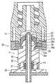
도 1은, 본 발명의 일실시 형태에 따른 수부재(1)의 개략 구성을 도시한 단면도이다. 수부재(1)는, 관상 부재(10)와, 관상 부재(10)의 선단(11)을 적어도 덮는 커버(20)를 구비한다. 이하의 설명의 편의를 위해, 도 1의 지면의 상측 및 하측을 수부재(1)의 「상측」 및 「하측」이라고 부른다. 단, 이 상하는, 수부재(1)의 실제의 사용시에서의 상하를 의미하는 것은 아니다.1 is a cross-sectional view showing a schematic configuration of a
관상 부재(10)는, 액상물이 흐르는 유로(13)가 그 길이 방향을 따라 형성된 통형상을 가지고 있다. 관상 부재(10)의 외주면은, 그 외경이 관상 부재(10)의 길이 방향을 따라 일정한 원주면, 또는, 그 외경이 기대(12)로부터 선단(11)에 가까워짐에 따라 작아지는 테이퍼면인 것이 바람직하다. 관상 부재(10)의 외주면의 선단(11) 근방의 위치에 횡공(14)이 형성되어 있다. 횡공(14)은, 유로(13)와 연통하여, 관상 부재(10)의 길이 방향과 대략 직교하는 방향으로 관상 부재(10)의 외주벽을 관통하는 관통공이다. 본 실시 형태에서는, 횡공(14)은, 관상 부재(10)의 직경 방향을 따라 한쌍 형성되어 있는데, 횡공(14)의 수는 이에 한정되지 않고, 1개 여도, 혹은 3개 이상이어도 된다. 액상물은 횡공(14)을 통해 유로(13)로부터 유출하고, 또는, 유로(13) 내에 유입한다. 도 7에 도시한 종래의 수루어(110)에서는, 그 선단에 개구(112)가 형성되어 있었는데, 본 실시 형태의 관상 부재(10)의 선단(11)에는, 유로(13)와 연통하는 개구(또는 관통공)는 형성되어 있지 않다. 기대(12)의 관상 부재(10)와는 반대측에는, 관상 부재(10)와 연통한, 대략 원통형상을 가지는 통형상부(18)가 형성되어 있다. 통형상부(18)에는, 관상 부재(10)에 대해 액상물을 수송하기 위해 예를 들어 유연성을 가지는 튜브(도시하지 않음)가 접속된다. 관상 부재(10)는, 실질적으로 강체라고 볼 수 있는 경질의 재료로 이루어지는 것이 바람직하다. 구체적으로는, 폴리아세탈, 폴리카보네이트 등의 수지 재료를 이용하고, 기대(12) 및 통형상부(18)와 더불어 일체 성형 등의 방법으로 작성할 수 있다.The tubular member (10) has a tubular shape in which a flow path (13) through which the liquid material flows is formed along its longitudinal direction. The outer circumferential surface of the
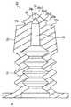
도 2A는, 커버(20)의 상방에서 본 사시도, 도 2B는 그 하방에서 본 사시도, 도 3A는 그 상면도, 도 3B는 그 측면도, 도 3C는 상하 방향을 따르는 그 단면도이다.Fig. 2A is a perspective view from above of the
커버(20)는, 대략 통형상을 가지는 외주벽(21)과, 외주벽(21)의 상단에 설치된 머리부(23)와, 외주벽(21)의 하단에 설치된 환상의 기부(28)를 구비한다. 커버 본체(20)는 가요성(유연성)을 가지는 재료(예를 들어 실리콘 고무, 이소프렌 고무)로 일체적으로 작성할 수 있다.The
외주벽(21)은, 그 상하 방향 치수가 단축하도록 탄성적으로 압축 변형 가능하다. 이를 실현하기 위해, 본 실시 형태에서는, 외주벽(21)은, 그 외경 치수 및 내경 치수가 일정 범위 내에서 상하 방향으로 일정 주기로 변화한 주름 상자형상을 가지고 있다. 본 실시 형태에서는, 외주벽(21)의 수평 방향을 따르는 단면 형상은 원형이지만, 사각형, 육각형 등의 다각형 등의 임의의 형상이어도 된다.The outer
머리부(23)에는, 외주벽(21)의 내부 공간과 연통한 내강(24)이 형성되어 있다. 내강(24)의 내주면의 형상은, 원주면 또는 외주벽(21)으로부터 멀어짐에 따라서 내경이 작아지는 원뿔면(테이퍼면)이다. 내강(24)의 최심부(24a)에는 머리부(23)를 상하 방향으로 관통하는 슬릿(25)이 형성되어 있다. 도 3A에 도시되어 있는 바와 같이, 슬릿(25)은, 그 상방에서 본 형상이 「-」(마이너스)자형상인 직선상의 절입이다. 관상 부재(10)가 슬릿(25)을 관통하고 있지 않은 통상 상태에서는, 슬릿(25)을 형성하는 서로 대향하는 단가장자리는 접촉하고 있는 것이 바람직하다.An
머리부(23)의 상면(23a)에는, 상면(23a)으로부터 돌출한 꼭대기부(26)가 형성되어 있다. 꼭대기부(26)의 선단은, 구면 등의 매끄럽게 돔형상으로 팽창한 볼록 곡면(26s)이다. 머리부(23)의 상면(23a)과 볼록 곡면(26s)의 사이에, 넥부(26n)가 형성되어 있다. 넥부(26n)에 인접하는, 볼록 곡면(26s)의 외경이 최대가 되는 부분을 꼭대기부 단가장자리(26e)라고 부른다. 넥부(26n)의 외경은, 꼭대기부 단가장자리(26e)의 외경보다 작다. 상방에서 보았을 때(도 3A를 참조), 꼭대기부 단가장자리(26e)의 외경은 원형이며, 상기 원형의 중심을 통해 슬릿(25)이 형성되어 있다.An apex 26 protruding from the
도 1에 도시하는 바와 같이, 커버(20)에, 그 기부(28)측으로부터 관상 부재(10)를 삽입하고, 커버(20)의 기부(28)를 관상 부재(10)의 기대(12)에 고정한다. 기대(12)에 대한 기부(28)의 고정 방법은 특별히 제한은 없고, 접착, 융착, 걸어맞춤, 끼워맞춤 등의 임의의 방법을 이용할 수 있다. 관상 부재(10)와 커버(20)를 정확하게 위치 결정하기 위해, 기대(12) 및 기부(28)에, 서로 끼워맞춤하는 끼워맞춤형상이 형성되어 있어도 된다.The
관상 부재(10)에 커버(20)를 장착했을 때, 관상 부재(10)의 선단(11)은 커버(20)의 머리부(23)의 내강(24) 내에 삽입된다. 커버(20)의 외주벽(21)이 압축 변형되어 있지 않은 도 1에 도시하는 상태에 있어서, 내강(24) 내에 삽입되는 관상 부재(10)의 부분을 선단 영역(15)이라고 부른다. 횡공(14)은, 이 선단 영역(15) 내에 형성되어 있다. 선단 영역(15)의 외경은, 내강(24)의 내경과 같거나 이보다 약간 크다. 따라서, 내강(24)의 내주면은 관상 부재(10)의 외주면에 밀착하고, 횡공(14)은 내강(24)의 내주면에 의해 막힌다. 또, 관상 부재(10)의 선단(11)과 내강(24)의 최심부(24a)는 이격하여, 양자간에 간극(24s)이 형성되어 있다. 간극(24s)을 사이에 두고, 관상 부재(10)의 선단(11)과 슬릿(25)이 대향하고 있다. 슬릿(25)은 실링되어 있는 것이 바람직하다. 이렇게 하여 간극(24s)은, 기밀로 실링되어 있는 것이 바람직하다.The
본 실시 형태의 수부재(1)와, 암부재로서의 니들레스 포트의 슬립 접속 및 그것의 분리를 이하에 설명한다.The
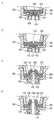
도 4A는, 접속 전의 수부재(1) 및 니들레스 포트(50)의 단면도이다. 니들레스 포트(50)는, 도 7에 도시한 니들레스 포트(150)와 마찬가지로, 셉텀(51)을 구비한다. 셉텀(51)은, 그 중앙부에 직선상의 슬릿(절입)(52)이 형성된 고무 등의 탄성 재료로 이루어지는 원판상의 격벽 부재이다. 셉텀(51)은, 대략 원통형상의 기체부(53)와 포트 캡(55)에 협지되어 고정되어 있다. 포트 캡(55)은, 수부재(1)에 대향하는 측에, 누름판(56)을 구비한다. 누름판(56)의 중앙에는 원형의 개구(57)가 형성되어 있다. 셉텀(51)의 슬릿(52)은 개구(57) 내에 노출하고 있다.4A is a cross-sectional view of the
도 4A에 도시하는 바와 같이, 수부재(1)와 니들레스 포트(50)를 대향시켜, 수부재(1)를 니들레스 포트(50)로 꽉 누른다. 처음에, 수부재(1)의 꼭대기부(26)의 볼록 곡면(26s)이 셉텀(51)의 외표면(51a)에 맞닿아, 양자가 밀착한다. 관상 부재(10)에 눌린 꼭대기부(26)는, 셉텀(51)을 탄성 변형시키면서 누름판(56)의 개구(57) 내에 침입하여, 마침내는, 도 4B에 도시하는 바와 같이, 꼭대기부(26)의 꼭대기부 단가장자리(26e)가 누름판(56)의 개구(57)의 개구 단가장자리(57e)를 넘어, 개구 단가장자리(57e)가 넥부(26n) 내에 끼워맞춤하고, 꼭대기부 단가장자리(26e)와 개구 단가장자리(57e)가 걸어맞춤한다. 이와 거의 동시에, 수부재(1)의 머리부(23)의 상면(23a)이 누름판(56)에 맞닿아, 머리부(23)의 니들레스 포트(50)측으로의 이동이 제한된다. 따라서, 더욱 수부재(1)를 니들레스 포트(50)에 밀어넣으면, 관상 부재(10)의 선단(11)이 머리부(23)의 슬릿(25)에 침입하여 이를 관통하고, 더욱 셉텀(51)의 슬릿(52)을 관통한다. 이 과정에서, 커버(20)의 외주벽(21)은 상하 방향으로 탄성적으로 압축 변형된다.The
이렇게 하여, 도 4C에 도시하는 바와 같이, 수부재(1)와 니들레스 포트(50)를 슬립 접속할 수 있다. 꼭대기부(26)가 누름판(56)의 개구(57) 내에 삽입되어, 셉텀(51)을 탄성 변형시키고 있다. 꼭대기부(26)의 볼록 곡면(26s)은 셉텀(51)의 외표면(51a)과 밀착하고 있다. 꼭대기부(26)의 꼭대기부 단가장자리(26e)가 누름판(56)의 개구 단가장자리(57e)와 걸어맞춤하고 있다. 관상 부재(10)는 머리부(23)의 슬릿(25) 및 셉텀(51)의 슬릿(52)을 차례로 관통하고 있다. 슬릿(52)의 단가장자리는, 관상 부재(10)의 외주면을 둘러싸고 또한 이것에 밀착하고 있다. 관상 부재(10)의 횡공(14)은 셉텀(51)에 대해 이측(꼭대기부(26)와는 반대측)에 위치하고, 횡공(14)을 개재하여 수부재(1)와 니들레스 포트(50)가 연통하고 있다. 따라서, 이 상태로 수부재(1) 및 니들레스 포트(50) 사이에 액상물이 흐를 수 있다. 셉텀(51)의 외표면(51a)은 꼭대기부(26)의 볼록 곡면(26s)과 밀착하고 있으므로, 도 8D에 도시한 종래의 구성과는 상이하여, 셉텀(51)의 외표면(51a)이 액상물에 접하는 일은 거의 없다.Thus, as shown in Fig. 4C, the
수부재(1) 및 니들레스 포트(50)간을 통과하는 액을 정지시킨 후, 도 4C의 상태로부터 수부재(1)를 니들레스 포트(50)로부터 뽑아낸다.After the liquid passing between the
상기 서술한 바와 같이 꼭대기부(26)의 꼭대기부 단가장자리(26e)가 누름판(56)의 개구 단가장자리(57e)와 걸어맞춤하고 있으므로, 머리부(23)는 니들레스 포트(50)에 대해 변위할 수 없다. 따라서, 관상 부재(10)가 셉텀(51) 및 머리부(23)에 대해 상대적으로 이동한다. 이 과정에서 슬릿(52)의 단가장자리가 관상 부재(10)의 외주면상을 슬라이드 하여, 관상 부재(10)의 외주면에 부착한 액상물을 벗겨낸다. 또, 커버(20)의 외주벽(21)은 신장한다.As described above, since the
도 5A는 관상 부재(10)를 셉텀(51)의 슬릿(52)으로부터 뽑아낸 직후의 상태를 도시한 단면도이다. 셉텀(51)의 슬릿(52)은, 관상 부재(10)가 뽑히면 즉시 탄성 회복하여 닫힌다. 커버(20)의 슬릿(25) 내에 관상 부재(10)의 선단(11)이 남아 있으므로, 슬릿(25)은 약간 열려 있다. 관상 부재(10)의 횡공(14)은, 머리부(23)의 내강(24) 내로 이동하고 있다. 내강(24)의 내주면은 관상 부재(10)의 외주면에 밀착하고 있어, 횡공(14)은 내강(24)의 내주면에 의해 막혀 있다.5A is a cross-sectional view showing a state immediately after the
도 5B는, 관상 부재(10)를 커버(20)의 슬릿(25)으로부터 뽑아낸 직후의 상태를 도시한 단면도이다. 셉텀(51)의 슬릿(52)과 마찬가지로, 커버(20)의 슬릿(25)은, 관상 부재(10)를 뽑아내면 즉시 탄성 회복하여 닫힌다. 슬릿(25)이 닫히는 것과 거의 병행하여, 관상 부재(10)의 선단(11)은 내강(24)의 최심부(24a)로부터 이격되어, 간극(24s)이 형성된다. 상기 서술한 바와 같이, 도 5A의 상태에 있어서, 셉텀(51)의 슬릿(52)은 이미 닫혀 있고, 또한, 내강(24)의 내주면은 관상 부재(10)의 외주면에 밀착하고 있다. 따라서, 도 5A에서 도 5B로 이행하는 과정에서 형성되는 간극(24s) 내에는, 그 용적 확대에 따라 부압이 발생한다. 이 부압에 의해, 셉텀(51)의 외표면(51a)과 꼭대기부(26)의 볼록 곡면(26s)의 사이에 잔존하는 액상물이 슬릿(25)을 개재하여 간극(24s) 내로 빨려들어간다.5B is a cross-sectional view showing a state immediately after the
그 후, 수부재(1)를 니들레스 포트(50)로부터 더 뽑아내면, 마침내 꼭대기부(26)의 꼭대기부 단가장자리(26e)와 누름판(56)의 개구 단가장자리(57e)의 걸어맞춤이 해제되고, 이어서 꼭대기부(26)의 볼록 곡면(26s)과 셉텀(51)의 외표면(51a)이 분리되며, 도 4A에 도시한 초기 상태로 돌아온다.Thereafter, when the
이상의 설명으로부터 이해할 수 있는 바와 같이, 본 실시 형태에 의하면, 수부재(1)를 니들레스 포트(50)로부터 분리하는 과정에서 형성되는 간극(24s)에 부압을 발생시킬 수 있으므로, 슬릿(25)의 근방에 잔존하는 액상물을 슬릿(25)을 통해 간극(24s) 내로 흡인할 수 있다. 그 결과, 수부재(1)와 니들레스 포트(50)를 분리한 후에 수부재(1)의 커버(20)의 외표면(즉, 볼록 곡면(26s)) 및 니들레스 포트(50)의 셉텀(51)의 외표면(51a)에 부착하는 액상물량을 줄일 수 있는 것이다.As can be understood from the above description, according to the present embodiment, since the negative pressure can be generated in the
또한, 머리부의 선단의 꼭대기부(26)에 볼록 곡면(26s)이 형성되어 있으므로, 수부재(1)와 니들레스 포트(50)를 접속했을 때에 볼록 곡면(26s)을 셉텀(51)의 외표면(51a)에 밀착시킬 수 있다. 따라서, 수부재(1)와 니들레스 포트(50)를 분리한 후에 볼록 곡면(26s) 및 외표면(51a)에 부착하는 액상물량을 더 줄일 수 있다.When the
또, 수부재(1)가 니들레스 포트(50)와 접속되어 있지 않은 비접속 상태(도 4A 참조)에 있어서, 관상 부재(10)의 횡공(14)은 커버(20)의 내강(24)의 내주면으로 막혀 있고, 또한, 커버(20)의 슬릿(25)은 닫혀 있으므로, 비접속 상태에 있어서 수부재(1)로부터 액상물이 누출할 일은 없다.4A) in which the
수부재(1)와 니들레스 포트(50)를 접속했을 때에, 도 4C에서 설명한 바와 같이, 꼭대기부(26)의 꼭대기부 단가장자리(26e)와 누름판(56)의 개구 단가장자리(57e)가 걸어맞춤한다. 이에 의해, 수부재(1)와 니들레스 포트(50)를 접속한 후, 양자를 분리할 때에, 관상 부재(10)를 커버(20)의 슬릿(25)으로부터 뽑아내기 전에, 커버(20)와 니들레스 포트(50)가 분리하는 것을 방지할 수 있다. 따라서, 수부재(1)와 니들레스 포트(50)를 분리한 후에 볼록 곡면(26s) 및 외표면(51a)에 부착하는 액상물량을 더 줄일 수 있다. 또, 수부재(1)와 니들레스 포트(50)를 분리할 때에, 커버(20)의 외주벽(21)을 초기 상태까지 확실히 신장시킬 수 있다.The
상기의 실시 형태는 예시이며, 본 발명은 상기의 실시 형태에 한정되지 않고, 적당히 변경할 수 있다.The above-described embodiment is an example, and the present invention is not limited to the above-described embodiment, but can be modified as appropriate.
상기의 실시 형태에서는, 머리부(23)의 상면(23a)으로부터 돌출한 꼭대기부(26)의 암부재(니들레스 포트(50))에 대향하는 측의 면에, 대략 구면형상의 볼록 곡면(26s)이 형성되어 있는데, 꼭대기부(26)의 외표면의 형상은 이에 한정되지 않는다. 도 6에, 본 발명의 수부재를 구성하는 다른 커버(20)의 단면도를 도시한다. 이 커버(20)의 꼭대기부(26)의 암부재에 대향하는 측의 면에는, 중앙으로부터 꼭대기부 단가장자리(26e)를 향해, 구면(26s1), 제1 원뿔대면(26s2), 제2 원뿔대면(26s3)이 이 순서로 배치되어 있다. 슬릿(25)은, 구면(26s1)에 형성되어 있다. 제2 원뿔대면(26s3)의 테이퍼 각도는 제1 원뿔대면(26s2)의 테이퍼 각도보다 크다. 제1 원뿔대면(26s2) 및 제2 원뿔대면(26s3)의 각각의 테이퍼 각도는 임의로 설정할 수 있다.A convex surface of a substantially spherical shape (a convex surface) is formed on the surface of the
도 6에 있어서, 구면(26s1)을 대신하여 평면을 형성해도 된다. 구면(26s1)과 제1 원뿔대면(26s2)을 대신하여, 하나의 원뿔면을 형성해도 된다. 이 경우, 상기 원뿔면의 중앙에 슬릿(25)이 형성된다. 제2 원뿔대면(26s3)을 대신하여, 제1 원뿔대면(26s2)의 외측에 환상의 평면을 형성해도 된다. 혹은, 제2 원뿔대면(26s3)을 생략해도 된다. 혹은, 또한, 다른 1 이상의 원뿔면을 추가해도 된다.In Fig. 6, a plane may be formed instead of the spherical surface 26s1. Instead of the spherical surface 26s1 and the first conical facing surface 26s2, one conical surface may be formed. In this case, a
상기의 설명에 있어서, 「구면」, 「원뿔대면」, 「원뿔면」은, 엄밀한 「구면」, 「원뿔대면」, 「원뿔면」을 각각 변형시킨 「대략 구면」, 「대략 원뿔대면」, 「대략 원뿔면」을 각각 포함하고 있어도 된다.In the above description, the terms "spherical surface", "conical surface", and "conical surface" mean "roughly spherical surface", "roughly conical surface", "roughly spherical surface" Quot ;, " conical surface ", respectively.
꼭대기부(26)의 표면 형상은, 상기 이외에도 임의로 설정할 수 있다. 일반적으로, 꼭대기부(26)의 암부재에 대향하는 측의 면은, 암부재를 향해 돌출한 볼록 곡면인 것이, 암부재의 외표면(상기의 실시 형태에서는 셉텀(51)의 외표면(51a))과의 밀착성이 향상하므로 바람직하다.The surface shape of the top 26 can be arbitrarily set in addition to the above. In general, the surface of the top 26 opposite to the arm member is a convex surface protruding toward the arm member. The outer surface of the arm member (the
상기의 실시 형태에서는, 머리부(23)의 선단에 꼭대기부(26)가 형성되어 있는데, 이 꼭대기부(26)를 생략할 수 있다. 꼭대기부(26)를 생략하면, 수부재와 암부재를 접속했을 때에, 커버와 암부재의 외표면(상기의 실시 형태에서는 셉텀(51)의 외표면(51a))이 밀착하지 않을 가능성이 있다. 그러나, 수부재와 암부재를 분리하는 과정에서 간극(24s) 내에 부압을 발생시킬 수 있으므로, 수부재와 암부재를 분리한 후에 커버 및 암부재의 외표면에 부착하는 액상물량을 줄일 수 있다.In the above embodiment, the top 26 is formed at the tip of the
상기의 실시 형태에서는, 커버(20)에, 암부재와 걸어맞춤하는 걸어맞춤 구조로서 넥부(26n)에 인접하는 꼭대기부 단가장자리(26e)가 형성되어 있는데, 상기 걸어맞춤 구조를 생략할 수 있다. 이 경우여도, 커버(20)의 외주벽(21)의 탄성력을 적절히 설정함으로써, 상기의 실시 형태와 마찬가지로 작용하는 커버를 실현하는 것이 가능하다.In the above embodiment, the
본 발명의 수부재는, 암부재와의 접속 상태를 안정적으로 유지하기 위해, 암부재와 걸어맞춤하는 걸어맞춤 부재를 구비하고 있어도 된다. 이러한 걸어맞춤 부재로서, 예를 들어 특허 문헌 2에 기재된 록레버를 이용할 수 있다.The male member of the present invention may be provided with an engaging member for engaging with the female member in order to stably maintain the connection state with the female member. As such an engagement member, for example, a lock lever described in Patent Document 2 can be used.
상기의 실시 형태의 수부재(1)는, 셉텀을 구비한 니들레스 포트에 접속 가능한 수루어였는데, 본 발명의 수부재는 이 이외의 암부재에 접속 가능해도 된다. 접속되는 암부재의 구성에 따라 본 발명의 수부재의 구성을 적당히 변경할 수 있다. 예를 들어, 본 발명의 수부재가, 바이알 병의 고무 마개에 천자할 수 있는 병침이어도 된다. 이 경우에는, 관상 부재(10)의 선단을 예리하게 형성하는 것, 관상 부재(10) 내에 액체용 및 기체용의 서로 독립한 2개의 유로를 병설하는 것 등, 주지의 변경을 행하는 것이 바람직하다.The
산업상의 이용 가능성Industrial availability
본 발명의 이용 분야는 특별히 제한은 없으나, 수액, 수혈, 체외 혈액 순환 등을 행하기 위한 수송 라인으로 사용되는 수부재에 바람직하게 이용할 수 있다. 또, 환자에게 투여하는 약액 등의 조제를 할 때에 사용되는 각종 커넥터의 수부재에 이용할 수도 있다. 특히, 누출 또는 증발하는 것을 방지할 필요가 있는 위험한 약제(예를 들어 항암제) 등을 취급하는 분야에서 바람직하게 이용할 수 있다. 또한, 의료용 이외의 식품 등의 액상물을 취급하는 각종 분야에서 사용되는 수부재에 이용할 수도 있다.The field of use of the present invention is not particularly limited, but can be suitably used for a water member used as a transport line for transfusion, blood transfusion, extracorporeal blood circulation, and the like. It can also be used as a member of various connectors used in the preparation of medicines for administration to patients. In particular, it can be advantageously used in the field of handling hazardous drugs (for example, anticancer drugs) which need to prevent leakage or evaporation. It can also be used for a water member used in various fields for handling liquid matters such as foods other than medical use.
1 수부재
10 관상 부재
11 관상 부재의 선단
13 관상 부재의 유로
14 관상 부재의 횡공
20 커버
21 외주벽
23 머리부
24 머리부의 내강
24a 내강의 최심부
24s 간극
25 슬릿
26 꼭대기부
26e 꼭대기부 단가장자리(걸어맞춤형상)
26s 볼록 곡면(구면)
26s1 구면
26s2 제1 원뿔대면
26s3 제2 원뿔대면
50 니들레스 포트(암부재)
51 셉텀
51a 셉텀의 외표면
52 셉텀의 슬릿1 member
10 tubular member
11 The tip of the tubular member
13 Channel of the tubular member
14 Horizontal cross-section of tubular member
20 cover
21 Outer wall
23 head
24 Head lining
24a The deepest part of the lumen
24s clearance
25 slits
26 Top
26e Top edge (engagement shape)
26s convex surface (spherical surface)
26s1 spherical
26s2 First cone facing
26s3 second cone facing
50 Needleless port (arm member)
51 Septum
51a outer surface of the septum
52 The slit of the septum
Claims (6)
Translated fromKorean상기 관상 부재의 외주면에, 상기 유로와 연통한 횡공이 형성되어 있고,
상기 커버는, 탄성적으로 압축 변형 가능한 외주벽과, 상기 외주벽의 일단에 설치된 머리부를 구비하며,
상기 머리부에는, 상기 관상 부재의 상기 선단이 삽입되는 내강이 형성되어 있고,
상기 내강의 최심부에는, 상기 머리부를 관통하는 슬릿이 형성되어 있으며,
상기 외주벽이 압축 변형되어 있지 않은 상태에 있어서, 상기 머리부의 상기 내강의 내주면이 상기 관상 부재의 상기 외주면과 밀착하여 상기 횡공을 막고, 또한, 상기 관상 부재의 선단과 상기 내강의 상기 최심부가 이격되어 있으며,
상기 외주벽이 압축 변형하도록 상기 관상 부재에 대해 상기 머리부를 변위시키면, 상기 관상 부재가 상기 슬릿을 관통하고, 상기 횡공이 상기 머리부로부터 노출하는 것을 특징으로 하는 수부재.A water member comprising a tubular member having a flow path through which liquid material flows, and a cover at least covering the tip of the tubular member,
A transverse hole communicating with the flow path is formed on an outer peripheral surface of the tubular member,
The cover has an outer peripheral wall which is resiliently compressible and deformable, and a head portion provided at one end of the outer peripheral wall,
The head portion is formed with a lumen into which the tip end of the tubular member is inserted,
A slit penetrating through the head portion is formed in the deepest portion of the lumen,
Wherein an inner circumferential surface of the lumen of the head portion is in close contact with the outer circumferential surface of the tubular member so as to close the transverse hole in a state in which the outer peripheral wall is not compressively deformed and that the distal end of the tubular member and the distal end portion of the lumen are spaced apart In addition,
Wherein when the head portion is displaced relative to the tubular member such that the outer peripheral wall is compressively deformed, the tubular member passes through the slit, and the transverse hole is exposed from the head portion.
상기 머리부의 선단에 돌출한 꼭대기부가 형성되어 있고, 상기 슬릿은 상기 꼭대기부에 형성되어 있는, 수부재.The method according to claim 1,
A top portion protruding from a tip end of the head portion is formed, and the slit is formed in the top portion.
상기 꼭대기부의 암부재에 대향하는 측의 면이, 암부재를 향해 돌출한 볼록 곡면을 포함하는, 수부재.The method of claim 2,
And a surface of the top portion opposite to the arm member includes a convex surface projecting toward the arm member.
상기 볼록 곡면이, 구면, 원뿔면, 또는 원뿔대면을 포함하는, 수부재.The method of claim 3,
Wherein the convexly curved surface comprises a spherical surface, a conical surface, or a conical surface.
상기 머리부에, 암부재와 걸어맞춤 가능한 걸어맞춤형상이 형성되어 있는, 수부재.The method according to any one of claims 1 to 4,
And a male member engageable with the female member is formed on the head portion.
상기 외주벽이 압축 변형되어 있지 않은 상태에 있어서, 상기 관상 부재의 상기 선단과 상기 내강의 상기 최심부의 사이에 기밀한 간극이 형성되는, 수부재.The method according to any one of claims 1 to 4,
Wherein an airtight gap is formed between the tip of the tubular member and the deepest portion of the lumen in a state where the outer peripheral wall is not compressively deformed.
Applications Claiming Priority (3)
| Application Number | Priority Date | Filing Date | Title |
|---|---|---|---|
| JP2011128166AJP6140916B2 (en) | 2011-06-08 | 2011-06-08 | Medical male parts |
| JPJP-P-2011-128166 | 2011-06-08 | ||
| PCT/JP2012/061220WO2012169295A1 (en) | 2011-06-08 | 2012-04-26 | Male member |
Publications (2)
| Publication Number | Publication Date |
|---|---|
| KR20140013100A KR20140013100A (en) | 2014-02-04 |
| KR101514915B1true KR101514915B1 (en) | 2015-04-23 |
Family
ID=47295866
Family Applications (1)
| Application Number | Title | Priority Date | Filing Date |
|---|---|---|---|
| KR1020137034969AActiveKR101514915B1 (en) | 2011-06-08 | 2012-04-26 | Male member |
Country Status (6)
| Country | Link |
|---|---|
| US (1) | US8974425B2 (en) |
| EP (1) | EP2719419B1 (en) |
| JP (1) | JP6140916B2 (en) |
| KR (1) | KR101514915B1 (en) |
| CN (1) | CN103596618B (en) |
| WO (1) | WO2012169295A1 (en) |
Families Citing this family (49)
| Publication number | Priority date | Publication date | Assignee | Title |
|---|---|---|---|---|
| US10478607B2 (en) | 2004-08-09 | 2019-11-19 | Carefusion 303, Inc. | Connector for transferring fluid and method of use |
| US7600530B2 (en) | 2004-08-09 | 2009-10-13 | Medegen, Inc. | Connector with check valve and method of use |
| US20060161115A1 (en) | 2004-11-05 | 2006-07-20 | Fangrow Thomas F | Soft-grip medical connector |
| US9168366B2 (en) | 2008-12-19 | 2015-10-27 | Icu Medical, Inc. | Medical connector with closeable luer connector |
| US8454579B2 (en) | 2009-03-25 | 2013-06-04 | Icu Medical, Inc. | Medical connector with automatic valves and volume regulator |
| US8323249B2 (en) | 2009-08-14 | 2012-12-04 | The Regents Of The University Of Michigan | Integrated vascular delivery system |
| USD644731S1 (en) | 2010-03-23 | 2011-09-06 | Icu Medical, Inc. | Medical connector |
| US8758306B2 (en) | 2010-05-17 | 2014-06-24 | Icu Medical, Inc. | Medical connectors and methods of use |
| US8814833B2 (en) | 2010-05-19 | 2014-08-26 | Tangent Medical Technologies Llc | Safety needle system operable with a medical device |
| WO2011146769A2 (en) | 2010-05-19 | 2011-11-24 | Tangent Medical Technologies Llc | Integrated vascular delivery system |
| JP5930481B2 (en)* | 2011-06-30 | 2016-06-08 | テルモ株式会社 | Connector assembly and male connector |
| ES2664517T3 (en) | 2011-09-09 | 2018-04-19 | Icu Medical, Inc. | Medical connectors with fluid resistant coupling interfaces |
| EP2916905A4 (en) | 2012-11-12 | 2016-11-09 | Icu Medical Inc | MEDICAL CONNECTION |
| US9278205B2 (en) | 2013-03-13 | 2016-03-08 | Carefusion 303, Inc. | Collapsible valve with internal dimples |
| US9370651B2 (en) | 2013-03-13 | 2016-06-21 | Carefusion 303, Inc. | Needleless connector with reduced trapped volume |
| US9089682B2 (en) | 2013-03-14 | 2015-07-28 | Carefusion 303, Inc. | Needleless connector with support member |
| US9144672B2 (en) | 2013-03-13 | 2015-09-29 | Carefusion 303, Inc. | Needleless connector with compressible valve |
| JP6370364B2 (en) | 2013-03-15 | 2018-08-08 | アイシーユー・メディカル・インコーポレーテッド | Medical connector |
| EP2862587A1 (en) | 2013-10-15 | 2015-04-22 | Becton Dickinson France | Tip cap assembly for closing an injection system |
| AU2014364218B2 (en) | 2013-12-11 | 2019-06-06 | Icu Medical, Inc. | Check valve |
| CA2937744C (en) | 2014-02-04 | 2022-08-09 | Icu Medical, Inc. | Self-priming systems and methods |
| US10596068B2 (en) | 2014-05-02 | 2020-03-24 | Jms Co., Ltd. | Drug container connector and male member cover |
| JP6582412B2 (en)* | 2014-05-02 | 2019-10-02 | 株式会社ジェイ・エム・エス | connector |
| JP6340898B2 (en)* | 2014-05-02 | 2018-06-13 | 株式会社ジェイ・エム・エス | Connector for pharmaceutical containers |
| WO2015166993A1 (en)* | 2014-05-02 | 2015-11-05 | 株式会社ジェイ・エム・エス | Drug container connector and male member cover |
| WO2016051759A1 (en)* | 2014-09-29 | 2016-04-07 | テルモ株式会社 | Female connector, male connector, and connector connection body |
| USD793551S1 (en) | 2014-12-03 | 2017-08-01 | Icu Medical, Inc. | Fluid manifold |
| USD786427S1 (en) | 2014-12-03 | 2017-05-09 | Icu Medical, Inc. | Fluid manifold |
| JP6578793B2 (en) | 2015-08-03 | 2019-09-25 | 株式会社ジェイ・エム・エス | Adapter for male connector and male connector with adapter |
| JP6825210B2 (en) | 2016-03-02 | 2021-02-03 | 株式会社ジェイ・エム・エス | Puncture needle connector and connecting tube |
| KR101868055B1 (en)* | 2016-08-05 | 2018-06-15 | (주)지메디 | Medical feeltering member for inning drug |
| JP6962923B2 (en)* | 2016-09-26 | 2021-11-05 | テルモ株式会社 | Male connector, medical equipment and connection method |
| WO2018174273A1 (en)* | 2017-03-24 | 2018-09-27 | テルモ株式会社 | Medical instrument |
| JP6924368B2 (en)* | 2017-05-26 | 2021-08-25 | 株式会社ジェイ・エム・エス | Male connector |
| CN107684645A (en)* | 2017-09-19 | 2018-02-13 | 江苏苏云医疗器材有限公司 | Medical connector |
| JP6858942B2 (en)* | 2018-11-27 | 2021-04-14 | ニプロ株式会社 | Hub assembly with bulkhead |
| US11708924B2 (en) | 2020-06-26 | 2023-07-25 | Carefusion 303, Inc. | Connector coupling assembly |
| CN112717270B (en)* | 2020-12-31 | 2024-03-29 | 深圳市迈威生物科技有限公司 | Repeatedly used drip-proof sealing joint |
| JP7573162B2 (en) | 2021-02-01 | 2024-10-25 | 株式会社ジェイ・エム・エス | Medical Connectors |
| US12208231B2 (en) | 2021-06-30 | 2025-01-28 | Carefusion 303, Inc. | Fluid connector system |
| US11882676B2 (en)* | 2021-08-20 | 2024-01-23 | Baidu Usa Llc | Server and rack codesign with a high reliable structure |
| CN113855561B (en)* | 2021-10-12 | 2023-11-07 | 深圳市迈威生物科技有限公司 | Self-sealing puncture outfit with low starting force |
| US12403295B2 (en) | 2022-08-11 | 2025-09-02 | Carefusion 303, Inc. | Fluid connector system |
| US12023462B2 (en)* | 2022-09-29 | 2024-07-02 | Carefusion 303, Inc. | Fluid connector system |
| US12208230B2 (en) | 2022-11-09 | 2025-01-28 | Carefusion 303, Inc. | Fluid connector assembly that seals flow paths when the connectors are disconnected |
| US12109387B2 (en) | 2022-11-11 | 2024-10-08 | Carefusion 303, Inc. | Connector coupling assembly |
| US12186518B2 (en) | 2023-04-25 | 2025-01-07 | Carefusion 303, Inc. | Fluid connector system |
| KR102854652B1 (en)* | 2023-06-26 | 2025-09-03 | 주식회사 수앤수메드 | Closed Type Drug Delivery Device with Needleless |
| US12420074B2 (en) | 2023-07-13 | 2025-09-23 | Carefusion 303, Inc. | Fluid connector assembly |
Citations (3)
| Publication number | Priority date | Publication date | Assignee | Title |
|---|---|---|---|---|
| US20040034325A1 (en) | 1995-12-15 | 2004-02-19 | Lopez George A. | Medical valve with fluid escape space |
| US20040122351A1 (en) | 2000-12-15 | 2004-06-24 | Kawasumi Laboratories, Inc. | Protective tool for therapeutic material delivery device, cartridge for therapeutic material delivery device, and a therapeutic material delivery device |
| US20050151105A1 (en) | 2004-01-13 | 2005-07-14 | Rymed Technologies, Inc. | Swabbable needle-free injection port valve system with neutral fluid displacement |
Family Cites Families (21)
| Publication number | Priority date | Publication date | Assignee | Title |
|---|---|---|---|---|
| JP2614939B2 (en) | 1990-10-29 | 1997-05-28 | 住友電気工業株式会社 | Superconducting element and fabrication method |
| US5549566A (en)* | 1994-10-27 | 1996-08-27 | Abbott Laboratories | Valved intravenous fluid line infusion device |
| US5700248A (en)* | 1995-12-15 | 1997-12-23 | Icu Medical, Inc. | Medical valve with tire seal |
| JP3389983B2 (en) | 1997-10-23 | 2003-03-24 | 株式会社ジェイ・エム・エス | Medical injection port |
| US6113068A (en)* | 1998-10-05 | 2000-09-05 | Rymed Technologies | Swabbable needleless injection port system having low reflux |
| US6745998B2 (en)* | 2001-08-10 | 2004-06-08 | Alaris Medical Systems, Inc. | Valved male luer |
| US6964406B2 (en)* | 2001-08-10 | 2005-11-15 | Alaris Medical Systems, Inc. | Valved male luer |
| JP4163975B2 (en) | 2002-02-25 | 2008-10-08 | 株式会社ジェイ・エム・エス | Lock connector for communication with connection port member with bulkhead |
| US7470262B2 (en) | 2003-03-17 | 2008-12-30 | Nipro Corporation | Medical valve |
| JP4649844B2 (en)* | 2003-03-17 | 2011-03-16 | ニプロ株式会社 | Medical valve |
| ITTO20040524A1 (en)* | 2004-07-27 | 2004-10-27 | Borla Ind | VALVE CONNECTOR FOR MEDICAL INFUSION LINES |
| US7887519B2 (en)* | 2005-01-14 | 2011-02-15 | Nypro Inc. | Valve with internal lifter |
| BRPI0717401A2 (en)* | 2006-10-25 | 2013-11-12 | Icu Medical Inc | CONNECTOR FOR MEDICAL USE |
| GB0806440D0 (en)* | 2008-04-09 | 2008-05-14 | Hospitalarios S A De C V Prod | Improvements relating to self-seating connectors |
| WO2010061743A1 (en) | 2008-11-25 | 2010-06-03 | 株式会社ジェイ・エム・エス | Connector |
| WO2010061742A1 (en) | 2008-11-25 | 2010-06-03 | 株式会社ジェイ・エム・エス | Connector |
| EP2550058B1 (en)* | 2010-05-06 | 2014-03-26 | ICU Medical, Inc. | Medical connector with closeable luer connector |
| US8758306B2 (en)* | 2010-05-17 | 2014-06-24 | Icu Medical, Inc. | Medical connectors and methods of use |
| US9381337B2 (en)* | 2010-07-19 | 2016-07-05 | Becton, Dickinson And Company | Luer connector |
| US8641675B2 (en)* | 2011-03-07 | 2014-02-04 | Becton, Dickinson And Company | Systems and methods for preventing septum damage in an intravascular device |
| US9867975B2 (en)* | 2011-05-23 | 2018-01-16 | Excelsior Medical Corporation | Antiseptic line cap |
- 2011
- 2011-06-08JPJP2011128166Apatent/JP6140916B2/enactiveActive
- 2012
- 2012-04-26KRKR1020137034969Apatent/KR101514915B1/enactiveActive
- 2012-04-26EPEP12796619.0Apatent/EP2719419B1/enactiveActive
- 2012-04-26CNCN201280027594.4Apatent/CN103596618B/enactiveActive
- 2012-04-26WOPCT/JP2012/061220patent/WO2012169295A1/enactiveApplication Filing
- 2012-04-26USUS14/124,157patent/US8974425B2/enactiveActive
Patent Citations (3)
| Publication number | Priority date | Publication date | Assignee | Title |
|---|---|---|---|---|
| US20040034325A1 (en) | 1995-12-15 | 2004-02-19 | Lopez George A. | Medical valve with fluid escape space |
| US20040122351A1 (en) | 2000-12-15 | 2004-06-24 | Kawasumi Laboratories, Inc. | Protective tool for therapeutic material delivery device, cartridge for therapeutic material delivery device, and a therapeutic material delivery device |
| US20050151105A1 (en) | 2004-01-13 | 2005-07-14 | Rymed Technologies, Inc. | Swabbable needle-free injection port valve system with neutral fluid displacement |
Also Published As
| Publication number | Publication date |
|---|---|
| US8974425B2 (en) | 2015-03-10 |
| CN103596618A (en) | 2014-02-19 |
| EP2719419B1 (en) | 2019-05-29 |
| JP2012254142A (en) | 2012-12-27 |
| JP6140916B2 (en) | 2017-06-07 |
| KR20140013100A (en) | 2014-02-04 |
| EP2719419A4 (en) | 2015-04-01 |
| US20140114292A1 (en) | 2014-04-24 |
| EP2719419A1 (en) | 2014-04-16 |
| CN103596618B (en) | 2016-03-09 |
| WO2012169295A1 (en) | 2012-12-13 |
Similar Documents
| Publication | Publication Date | Title |
|---|---|---|
| KR101514915B1 (en) | Male member | |
| US7025744B2 (en) | Injection site for male luer or other tubular connector | |
| US8647312B2 (en) | Injection site for male luer or other tubular connector | |
| EP0781151B1 (en) | Valved intravenous fluid line infusion device | |
| KR102506175B1 (en) | Pooling device for single or multiple containers | |
| JP5994400B2 (en) | Female connector | |
| WO2017217105A1 (en) | Cap for sucking in air | |
| CZ187398A3 (en) | Medical valve | |
| JP6002689B2 (en) | Coupling device and kit | |
| US20240033182A1 (en) | Coupling device for an adapter for a vial, adapter for a vial, set comprising an adapter of this type, and system comprising an adapter of this type | |
| JP6318531B2 (en) | Male connector, female connector, and connector set | |
| WO2013141137A1 (en) | Bottle needle provided with cover | |
| JP5625895B2 (en) | Male member cover and male member with cover | |
| JP6135960B2 (en) | Medical male parts | |
| JP5630288B2 (en) | Male member cover and male member with cover | |
| KR102593071B1 (en) | Connector for a medical container | |
| JP6741209B2 (en) | Filter assembly | |
| KR20200112136A (en) | Needle free type injection connector | |
| JP2012217639A (en) | Male member cover and male member with cover | |
| JP2006212084A (en) | Connector | |
| HK1247550B (en) | Septum holders for use in syringe connectors |
Legal Events
| Date | Code | Title | Description |
|---|---|---|---|
| A201 | Request for examination | ||
| PA0105 | International application | Patent event date:20131230 Patent event code:PA01051R01D Comment text:International Patent Application | |
| PA0201 | Request for examination | ||
| PG1501 | Laying open of application | ||
| E902 | Notification of reason for refusal | ||
| PE0902 | Notice of grounds for rejection | Comment text:Notification of reason for refusal Patent event date:20140930 Patent event code:PE09021S01D | |
| E701 | Decision to grant or registration of patent right | ||
| PE0701 | Decision of registration | Patent event code:PE07011S01D Comment text:Decision to Grant Registration Patent event date:20150318 | |
| GRNT | Written decision to grant | ||
| PR0701 | Registration of establishment | Comment text:Registration of Establishment Patent event date:20150417 Patent event code:PR07011E01D | |
| PR1002 | Payment of registration fee | Payment date:20150417 End annual number:3 Start annual number:1 | |
| PG1601 | Publication of registration | ||
| FPAY | Annual fee payment | Payment date:20180410 Year of fee payment:4 | |
| PR1001 | Payment of annual fee | Payment date:20180410 Start annual number:4 End annual number:4 |