KR101514827B1 - Secondary battery and method for manufacturing the same - Google Patents
Secondary battery and method for manufacturing the sameDownload PDFInfo
- Publication number
- KR101514827B1 KR101514827B1KR1020130020744AKR20130020744AKR101514827B1KR 101514827 B1KR101514827 B1KR 101514827B1KR 1020130020744 AKR1020130020744 AKR 1020130020744AKR 20130020744 AKR20130020744 AKR 20130020744AKR 101514827 B1KR101514827 B1KR 101514827B1
- Authority
- KR
- South Korea
- Prior art keywords
- electrode assembly
- assembly
- cap
- safety vent
- gasket
- Prior art date
- Legal status (The legal status is an assumption and is not a legal conclusion. Google has not performed a legal analysis and makes no representation as to the accuracy of the status listed.)
- Active
Links
Images


Classifications
- H—ELECTRICITY
- H01—ELECTRIC ELEMENTS
- H01M—PROCESSES OR MEANS, e.g. BATTERIES, FOR THE DIRECT CONVERSION OF CHEMICAL ENERGY INTO ELECTRICAL ENERGY
- H01M50/00—Constructional details or processes of manufacture of the non-active parts of electrochemical cells other than fuel cells, e.g. hybrid cells
- H01M50/30—Arrangements for facilitating escape of gases
- H—ELECTRICITY
- H01—ELECTRIC ELEMENTS
- H01M—PROCESSES OR MEANS, e.g. BATTERIES, FOR THE DIRECT CONVERSION OF CHEMICAL ENERGY INTO ELECTRICAL ENERGY
- H01M10/00—Secondary cells; Manufacture thereof
- H01M10/05—Accumulators with non-aqueous electrolyte
- H01M10/058—Construction or manufacture
- H—ELECTRICITY
- H01—ELECTRIC ELEMENTS
- H01M—PROCESSES OR MEANS, e.g. BATTERIES, FOR THE DIRECT CONVERSION OF CHEMICAL ENERGY INTO ELECTRICAL ENERGY
- H01M10/00—Secondary cells; Manufacture thereof
- H01M10/05—Accumulators with non-aqueous electrolyte
- H01M10/052—Li-accumulators
- H—ELECTRICITY
- H01—ELECTRIC ELEMENTS
- H01M—PROCESSES OR MEANS, e.g. BATTERIES, FOR THE DIRECT CONVERSION OF CHEMICAL ENERGY INTO ELECTRICAL ENERGY
- H01M50/00—Constructional details or processes of manufacture of the non-active parts of electrochemical cells other than fuel cells, e.g. hybrid cells
- H01M50/10—Primary casings; Jackets or wrappings
- H01M50/102—Primary casings; Jackets or wrappings characterised by their shape or physical structure
- H01M50/107—Primary casings; Jackets or wrappings characterised by their shape or physical structure having curved cross-section, e.g. round or elliptic
- H—ELECTRICITY
- H01—ELECTRIC ELEMENTS
- H01M—PROCESSES OR MEANS, e.g. BATTERIES, FOR THE DIRECT CONVERSION OF CHEMICAL ENERGY INTO ELECTRICAL ENERGY
- H01M50/00—Constructional details or processes of manufacture of the non-active parts of electrochemical cells other than fuel cells, e.g. hybrid cells
- H01M50/10—Primary casings; Jackets or wrappings
- H01M50/147—Lids or covers
- H01M50/148—Lids or covers characterised by their shape
- H01M50/152—Lids or covers characterised by their shape for cells having curved cross-section, e.g. round or elliptic
- H—ELECTRICITY
- H01—ELECTRIC ELEMENTS
- H01M—PROCESSES OR MEANS, e.g. BATTERIES, FOR THE DIRECT CONVERSION OF CHEMICAL ENERGY INTO ELECTRICAL ENERGY
- H01M50/00—Constructional details or processes of manufacture of the non-active parts of electrochemical cells other than fuel cells, e.g. hybrid cells
- H01M50/10—Primary casings; Jackets or wrappings
- H01M50/147—Lids or covers
- H01M50/166—Lids or covers characterised by the methods of assembling casings with lids
- H01M50/169—Lids or covers characterised by the methods of assembling casings with lids by welding, brazing or soldering
- H—ELECTRICITY
- H01—ELECTRIC ELEMENTS
- H01M—PROCESSES OR MEANS, e.g. BATTERIES, FOR THE DIRECT CONVERSION OF CHEMICAL ENERGY INTO ELECTRICAL ENERGY
- H01M50/00—Constructional details or processes of manufacture of the non-active parts of electrochemical cells other than fuel cells, e.g. hybrid cells
- H01M50/10—Primary casings; Jackets or wrappings
- H01M50/183—Sealing members
- H01M50/186—Sealing members characterised by the disposition of the sealing members
- H—ELECTRICITY
- H01—ELECTRIC ELEMENTS
- H01M—PROCESSES OR MEANS, e.g. BATTERIES, FOR THE DIRECT CONVERSION OF CHEMICAL ENERGY INTO ELECTRICAL ENERGY
- H01M50/00—Constructional details or processes of manufacture of the non-active parts of electrochemical cells other than fuel cells, e.g. hybrid cells
- H01M50/30—Arrangements for facilitating escape of gases
- H01M50/317—Re-sealable arrangements
- H01M50/325—Re-sealable arrangements comprising deformable valve members, e.g. elastic or flexible valve members
- H—ELECTRICITY
- H01—ELECTRIC ELEMENTS
- H01M—PROCESSES OR MEANS, e.g. BATTERIES, FOR THE DIRECT CONVERSION OF CHEMICAL ENERGY INTO ELECTRICAL ENERGY
- H01M50/00—Constructional details or processes of manufacture of the non-active parts of electrochemical cells other than fuel cells, e.g. hybrid cells
- H01M50/30—Arrangements for facilitating escape of gases
- H01M50/342—Non-re-sealable arrangements
- H01M50/3425—Non-re-sealable arrangements in the form of rupturable membranes or weakened parts, e.g. pierced with the aid of a sharp member
- H—ELECTRICITY
- H01—ELECTRIC ELEMENTS
- H01M—PROCESSES OR MEANS, e.g. BATTERIES, FOR THE DIRECT CONVERSION OF CHEMICAL ENERGY INTO ELECTRICAL ENERGY
- H01M50/00—Constructional details or processes of manufacture of the non-active parts of electrochemical cells other than fuel cells, e.g. hybrid cells
- H01M50/50—Current conducting connections for cells or batteries
- H01M50/543—Terminals
- H01M50/545—Terminals formed by the casing of the cells
- H—ELECTRICITY
- H01—ELECTRIC ELEMENTS
- H01M—PROCESSES OR MEANS, e.g. BATTERIES, FOR THE DIRECT CONVERSION OF CHEMICAL ENERGY INTO ELECTRICAL ENERGY
- H01M50/00—Constructional details or processes of manufacture of the non-active parts of electrochemical cells other than fuel cells, e.g. hybrid cells
- H01M50/50—Current conducting connections for cells or batteries
- H01M50/572—Means for preventing undesired use or discharge
- H01M50/574—Devices or arrangements for the interruption of current
- H01M50/578—Devices or arrangements for the interruption of current in response to pressure
- H—ELECTRICITY
- H01—ELECTRIC ELEMENTS
- H01M—PROCESSES OR MEANS, e.g. BATTERIES, FOR THE DIRECT CONVERSION OF CHEMICAL ENERGY INTO ELECTRICAL ENERGY
- H01M50/00—Constructional details or processes of manufacture of the non-active parts of electrochemical cells other than fuel cells, e.g. hybrid cells
- H01M50/50—Current conducting connections for cells or batteries
- H01M50/572—Means for preventing undesired use or discharge
- H01M50/574—Devices or arrangements for the interruption of current
- H01M50/581—Devices or arrangements for the interruption of current in response to temperature
- H—ELECTRICITY
- H01—ELECTRIC ELEMENTS
- H01M—PROCESSES OR MEANS, e.g. BATTERIES, FOR THE DIRECT CONVERSION OF CHEMICAL ENERGY INTO ELECTRICAL ENERGY
- H01M2200/00—Safety devices for primary or secondary batteries
- H01M2200/10—Temperature sensitive devices
- H01M2200/106—PTC
- Y—GENERAL TAGGING OF NEW TECHNOLOGICAL DEVELOPMENTS; GENERAL TAGGING OF CROSS-SECTIONAL TECHNOLOGIES SPANNING OVER SEVERAL SECTIONS OF THE IPC; TECHNICAL SUBJECTS COVERED BY FORMER USPC CROSS-REFERENCE ART COLLECTIONS [XRACs] AND DIGESTS
- Y02—TECHNOLOGIES OR APPLICATIONS FOR MITIGATION OR ADAPTATION AGAINST CLIMATE CHANGE
- Y02E—REDUCTION OF GREENHOUSE GAS [GHG] EMISSIONS, RELATED TO ENERGY GENERATION, TRANSMISSION OR DISTRIBUTION
- Y02E60/00—Enabling technologies; Technologies with a potential or indirect contribution to GHG emissions mitigation
- Y02E60/10—Energy storage using batteries
- Y—GENERAL TAGGING OF NEW TECHNOLOGICAL DEVELOPMENTS; GENERAL TAGGING OF CROSS-SECTIONAL TECHNOLOGIES SPANNING OVER SEVERAL SECTIONS OF THE IPC; TECHNICAL SUBJECTS COVERED BY FORMER USPC CROSS-REFERENCE ART COLLECTIONS [XRACs] AND DIGESTS
- Y02—TECHNOLOGIES OR APPLICATIONS FOR MITIGATION OR ADAPTATION AGAINST CLIMATE CHANGE
- Y02P—CLIMATE CHANGE MITIGATION TECHNOLOGIES IN THE PRODUCTION OR PROCESSING OF GOODS
- Y02P70/00—Climate change mitigation technologies in the production process for final industrial or consumer products
- Y02P70/50—Manufacturing or production processes characterised by the final manufactured product
- Y—GENERAL TAGGING OF NEW TECHNOLOGICAL DEVELOPMENTS; GENERAL TAGGING OF CROSS-SECTIONAL TECHNOLOGIES SPANNING OVER SEVERAL SECTIONS OF THE IPC; TECHNICAL SUBJECTS COVERED BY FORMER USPC CROSS-REFERENCE ART COLLECTIONS [XRACs] AND DIGESTS
- Y10—TECHNICAL SUBJECTS COVERED BY FORMER USPC
- Y10T—TECHNICAL SUBJECTS COVERED BY FORMER US CLASSIFICATION
- Y10T29/00—Metal working
- Y10T29/49—Method of mechanical manufacture
- Y10T29/49002—Electrical device making
- Y10T29/49108—Electric battery cell making
- Y10T29/4911—Electric battery cell making including sealing
Landscapes
- Chemical & Material Sciences (AREA)
- Chemical Kinetics & Catalysis (AREA)
- Electrochemistry (AREA)
- General Chemical & Material Sciences (AREA)
- Engineering & Computer Science (AREA)
- Manufacturing & Machinery (AREA)
- Sealing Battery Cases Or Jackets (AREA)
- Secondary Cells (AREA)
- Connection Of Batteries Or Terminals (AREA)
- Gas Exhaust Devices For Batteries (AREA)
Abstract
Translated fromKoreanDescription
Translated fromKorean본 발명은 이차 전지를 제조하는 기술에 관한 것으로, 더욱 상세하게는 비딩부가 형성되지 않으면서도 캡 조립체와 전지 케이스를 용접하지 않을 수 있도록 함으로써 용량 및 안전성이 향상된 이차 전지와 그 제조 방법에 관한 것이다.BACKGROUND OF THE INVENTION 1. Field of the Invention [0001] The present invention relates to a technique for manufacturing a secondary battery, and more particularly, to a secondary battery improved in capacity and safety by not welding a cap assembly and a battery case without forming a beading portion and a manufacturing method thereof.
일반적으로, 이차 전지는 충전이 불가능한 일차 전지와 달리, 충방전이 가능한 전지를 의미하며, 휴대폰, 노트북 컴퓨터, 캠코더 등의 전자기기 또는 전기 자동차 등에 널리 사용되고 있다. 특히, 리튬 이차 전지는 작동 전압이 3.6V 가량으로서, 전자 장비의 전원으로 많이 사용되는 니켈-카드뮴 전지 또는 니켈-수소 전지보다 약 3배의 용량을 가지며, 단위 중량당 에너지 밀도가 높기 때문에 그 활용 정도가 급속도로 증가되는 추세에 있다.2. Description of the Related Art Generally, a secondary battery is a battery capable of being charged and discharged unlike a primary battery which can not be charged, and is widely used in electronic devices such as mobile phones, notebook computers, camcorders, and electric vehicles. Particularly, the lithium secondary battery has an operating voltage of about 3.6 V, has a capacity about three times that of a nickel-cadmium battery or a nickel-hydrogen battery widely used as a power source for electronic equipment, and has a high energy density per unit weight. Is rapidly increasing.
이러한 리튬 이차 전지는 주로 리튬계 산화물과 탄소재를 각각 양극 활물질과 음극 활물질로 사용한다. 리튬 이차 전지는, 이러한 양극 활물질과 음극 활물질이 각각 도포된 양극판과 음극판이 세퍼레이터를 사이에 두고 배치된 전극 조립체와, 전극 조립체를 전해액과 함께 밀봉 수납하는 전지 케이스(외장재)를 구비한다.These lithium secondary batteries mainly use a lithium-based oxide and a carbonaceous material as a cathode active material and an anode active material, respectively. The lithium secondary battery includes an electrode assembly in which a positive electrode plate and a negative electrode plate each coated with such a positive electrode active material and a negative electrode active material are disposed with a separator interposed therebetween, and a battery case (outer case) sealingly accommodates the electrode assembly together with the electrolyte solution.
한편, 리튬 이차 전지는 전지 케이스의 종류에 따라, 전극 조립체가 금속 캔에 내장되어 있는 캔형 이차 전지와 전극 조립체가 알루미늄 라미네이트 시트의 파우치에 내장되어 있는 파우치형 이차 전지로 분류될 수 있다. 그리고, 캔형 이차 전지는 다시 금속 캔의 형상에 따라 원통형 전지와 각형 전지로 분류될 수 있다. 이러한 각형 또는 원통형 이차 전지의 외장재는 개방단이 형성된 전지 케이스 및 전지 케이스의 개방단에 밀봉 결합되는 캡 조립체를 구비한다.Meanwhile, the lithium secondary battery can be classified into a can type secondary battery in which an electrode assembly is embedded in a metal can, and a pouch type secondary battery in which an electrode assembly is embedded in a pouch of an aluminum laminate sheet, depending on the type of the battery case. The can-type secondary battery can be further divided into a cylindrical battery and a prismatic battery depending on the shape of the metal can. The casing of the rectangular or cylindrical secondary battery includes a battery case having an open end and a cap assembly sealingly coupled to an open end of the battery case.
도 1은, 전지 케이스에 비딩부가 형성된 종래의 원통형 이차 전지의 개략적인 단면도이다.1 is a schematic cross-sectional view of a conventional cylindrical secondary battery in which a battery case has a beading portion.
도 1을 참조하면, 일반적으로 원통형 이차 전지는 하단은 밀폐되고 상단은 개방된 원통형 전지 케이스(20), 전지 케이스(20)의 내부에 수용되는 젤리-롤 형태의 전극 조립체(30), 전지 케이스(20)의 상부에 결합되는 캡 조립체(10), 캡 조립체(10)를 장착하기 위해 전지 케이스(20)의 선단에 마련된 비딩부(40) 및 전지를 밀봉하기 위한 클림핑 부위(50)를 구비한다.Referring to FIG. 1, a cylindrical rechargeable battery includes a
전극 조립체(30)는 통상적으로 양극판과 음극판 사이에 세퍼레이터가 개재된 상태로 젤리-롤 형태로 권취된 구조이며, 양극판에는 양극 리드(31)가 부착되어 캡 조립체(10)에 접속되어 있고, 음극판에는 음극 리드(32)가 부착되어 전지 케이스(20)의 하단에 접속되어 있다.The
캡 조립체(10)는 양극 단자를 형성하는 탑 캡(11), 전지 내부의 압력 상승시 전류를 차단하고 및/또는 가스를 배기하는 안전 벤트(12), 특정 부분을 제외하고 안전 벤트(12)를 전류차단부재(15)로부터 전기적으로 분리시키는 절연부재(13), 양극판에 연결된 양극 리드(31)가 접속되어 있는 전류차단부재(14)가 순차적으로 적층된 구조를 갖는다. 그리고, 이러한 캡 조립체(10)는 가스켓(15)에 장착된 상태로 전지 케이스(20)의 비딩부(40)에 안착된다. 따라서, 정상적인 작동 조건에서 전극 조립체(30)의 양극은 양극 리드(31), 전류차단부재(14) 및 안전 벤트(12)를 경유하여 탑 캡(11)에 연결되어 통전을 이룬다.The
하지만, 이와 같은 비딩부가 구비된 종래의 이차 전지의 경우, 캡 조립체(10)를 결합 및 고정하기 위해 전지 케이스(20)에 비딩부(40)가 형성되어야 하는데, 이러한 비딩부(40)가 차지하는 부분만큼 전극 조립체(30)의 수납 용량이 작아지므로 결국에는 전지 용량이 감소되는 문제점이 있다. 따라서, 이러한 문제를 해결하기 위해 최근에는 전지 케이스(20)에 비딩부(40)가 형성되지 않은 이차 전지가 제안되고 있다.However, in the case of a conventional secondary battery having such a beading portion, a
도 2는, 전지 케이스(20)에 비딩부가 형성되지 않은 종래의 원통형 이차 전지의 개략적인 단면도이다.2 is a schematic cross-sectional view of a conventional cylindrical secondary battery in which a
도 2를 참조하면, 전지 케이스(20)에 비딩부가 형성되어 있지 않다. 그리고, 캡 조립체(10)를 전지 케이스(20)의 상단에서, L로 표시된 부분과 같이, 레이저 용접 등의 방식으로 결합시켜 전지 케이스(20)를 밀봉시킨다. 이때, 캡 조립체(10)를 전지 케이스(20)와 용접시키기 위해서는 도면에 도시된 바와 같이, 캡 조립체(10)의 최외곽에 커버(16)를 구비하는 것이 통상적이다. 이러한 커버(16)는 전지 케이스(20)와 용접을 하기 위한 구성요소이기 때문에 전지 케이스(20)와 용접이 가능한 재질, 이를테면 금속 재질로 이루어질 수 있다.Referring to FIG. 2, the
이처럼 종래의 비딩부가 형성되지 않은 이차 전지의 경우, 캡 조립체(10)와 전지 케이스(20)를 용접하는 공정이 수행된다. 그런데 이와 같은 용접 공정에서는, 용접 찌꺼기가 발생할 수 있으며, 이러한 용접 찌꺼기는 캡 조립체(10)나 전극 조립체(30)에 부착되어 전지 내부에서 쇼트를 일으킬 우려가 있다.In the case of the secondary battery in which the conventional beading is not formed, a process of welding the
또한, 캡 조립체(10)와 전지 케이스(20)의 용접시에는 열이 발생할 수 있는데, 이러한 열은 캡 조립체(10)의 여러 구성요소를 손상시킬 수 있다. 뿐만 아니라, 캡 조립체(10)에 전지 케이스(20)와 용접하기 위한 금속과 같은 재질의 커버(16)를 별도로 구비해야 하기 때문에 캡 조립체(10)의 구조가 더 복잡해지고 제조 비용이 증가할 수 있으며, 이차 전지의 무게를 증가시킬 수 있다.Heat can also be generated during welding of the
따라서, 본 발명은 상기와 같은 문제점을 해결하기 위해 창안된 것으로서, 전지 케이스에 비딩부가 형성되지 않아 용량이 향상될 수 있으면서도, 캡 조립체와 전지 케이스가 용접되지 않아 용접 찌꺼기로 인한 쇼트 및 캡 조립체의 손상이 방지되고 생산성이 향상될 수 있는 이차 전지 및 이를 제조하는 방법을 제공하는 것을 목적으로 한다.SUMMARY OF THE INVENTION Accordingly, the present invention has been made keeping in mind the above problems occurring in the prior art, and it is an object of the present invention to provide a cap assembly and a battery case, A secondary battery capable of preventing damage and improving productivity, and a method of manufacturing the secondary battery.
본 발명의 다른 목적 및 장점들은 하기의 설명에 의해서 이해될 수 있으며, 본 발명의 실시예에 의해 보다 분명하게 알게 될 것이다. 또한, 본 발명의 목적 및 장점들은 특허 청구 범위에 나타낸 수단 및 그 조합에 의해 실현될 수 있음을 쉽게 알 수 있을 것이다.Other objects and advantages of the present invention will become apparent from the following description, and it will be understood by those skilled in the art that the present invention is not limited thereto. It will also be readily apparent that the objects and advantages of the invention may be realized and attained by means of the instrumentalities and combinations particularly pointed out in the appended claims.
상기와 같은 목적을 달성하기 위한 본 발명에 따른 이차 전지는, 비딩부가 형성되지 않은 이차 전지로서, 양극판 및 음극판이 세퍼레이터를 사이에 두고 배치된 전극 조립체; 내부 공간에 상기 전극 조립체 및 전해액을 수납하고 상단 및 하단이 개방되어 있으며 상단이 내측 방향으로 절곡된 상부 캔 및 상기 상부 캔의 하단에 결합되어 하단을 밀폐시키는 하부 밀폐부재를 포함하는 전지 케이스; 및 최상부에 돌출된 형태로 배치되어 양극 단자를 형성하는 탑 캡, 상기 탑 캡의 하부에서 상기 전지 케이스의 내압 증가시 형태가 변형되는 안전 벤트, 및 상기 탑 캡 및 상기 안전 벤트의 테두리들을 감싸는 가스켓을 포함하는 캡 조립체를 포함한다.According to an aspect of the present invention, there is provided a secondary battery including a positive electrode plate and a negative electrode plate with a separator interposed therebetween; A battery case including an upper can accommodating the electrode assembly and an electrolyte solution in an inner space and having an upper end and a lower end opened and an upper end bent in the inner direction and a lower sealing member coupled to a lower end of the upper can to seal the lower end; A top cap which is disposed in a protruding shape at the top to form a positive terminal, a safety vent in which the shape of the battery case is deformed when the internal pressure of the battery case is increased at a lower portion of the top cap, And a cap assembly.
바람직하게는, 상기 가스켓은, 상단부가 상기 상부 캔의 상단 절곡부 내면에 접촉되고, 하단부가 상기 전극 조립체의 상면에 접촉된다.Preferably, the upper end of the gasket is in contact with the inner surface of the upper bent portion of the upper can, and the lower end of the gasket is in contact with the upper surface of the electrode assembly.
또한 바람직하게는, 상기 전극 조립체의 상부에 상부 절연판을 더 포함하고,Further, preferably, an upper insulating plate is further provided on the electrode assembly,
상기 가스켓은, 상단부가 상기 상부 캔의 상단 절곡부 내면에 접촉되고, 하단부가 상기 상부 절연판의 상면에 접촉된다.The upper end of the gasket is in contact with the inner surface of the upper bent portion of the upper can, and the lower end of the gasket is in contact with the upper surface of the upper insulating plate.
또한 바람직하게는, 상기 상부 캔과 상기 하부 밀폐부재는, 레이저 용접에 의해 결합된다.Also preferably, the upper can and the lower closure member are joined by laser welding.
또한 바람직하게는, 상기 하부 밀폐부재는 홈이 형성되어 있고, 상기 상부 캔은 상기 하부 밀폐부재의 홈에 삽입된다.Further, preferably, the lower sealing member is formed with a groove, and the upper can is inserted into the groove of the lower sealing member.
또한 상기와 같은 목적을 달성하기 위한 본 발명에 따른 배터리 팩은, 상술한 이차 전지를 포함한다.According to another aspect of the present invention, there is provided a battery pack including the secondary battery.
또한 상기와 같은 목적을 달성하기 위한 본 발명에 따른 이차 전지 제조 방법은, 비딩부가 형성되지 않은 이차 전지를 제조하는 방법으로서, 양극판 및 음극판이 세퍼레이터를 사이에 두고 배치된 전극 조립체를 준비하는 단계; 상기 전극 조립체 및 전해액을 수납 가능하도록 내부 공간이 형성되고 상단 및 하단이 개방되어 상단이 내측 방향으로 절곡된 상부 캔 및 상기 상부 캔과 분리된 하부 밀폐부재를 포함하는 전지 케이스를 준비하는 단계; 상기 최상부에 돌출된 형태로 배치되어 양극 단자를 형성하는 탑 캡, 상기 탑 캡의 하부에서 상기 전지 케이스의 내압 증가시 형태가 변형되는 안전 벤트, 및 상기 탑 캡 및 상기 안전 벤트의 테두리들을 감싸는 가스켓을 포함하는 캡 조립체를 준비하는 단계; 상기 가스켓의 상단부가 상기 상부 캔의 절곡된 상부 내면에 접촉되도록 상기 캡 조립체를 상기 상부 캔의 하단 개방부를 통하여 상부 방향으로 삽입하는 단계; 상기 캡 조립체의 하부에 위치하도록 상기 전극 조립체를 상기 상부 캔의 하단 개방부를 통하여 상부 방향으로 삽입하는 단계; 및 상기 상부 캔의 하단을 밀폐시키도록 상기 하부 밀폐부재를 상기 상부 캔의 하단에 결합하는 단계를 포함한다.According to another aspect of the present invention, there is provided a method of manufacturing a secondary battery in which a bead is not formed, the method comprising: preparing an electrode assembly having a positive electrode and a negative electrode disposed with a separator interposed therebetween; Preparing a battery case including an upper can and an upper can, wherein an upper space and an upper space are opened to accommodate the electrode assembly and the electrolyte, and an upper end is bent in an inner direction; A top cap which is disposed on the top of the top cap to form a positive terminal, a safety vent whose shape is deformed when the internal pressure of the battery case is increased at a lower portion of the top cap, and a gasket Providing a cap assembly comprising: Inserting the cap assembly in an upper direction through a lower end opening of the upper can such that an upper end of the gasket is in contact with a curved upper inner surface of the upper can; Inserting the electrode assembly in an upper direction through a lower end opening of the upper can so as to be positioned below the cap assembly; And coupling the lower closure member to the lower end of the upper can to seal the lower end of the upper can.
바람직하게는, 상기 전극 조립체의 삽입 단계는, 상기 전극 조립체의 상면이 상기 가스켓의 하단부에 접촉되도록 상기 전극 조립체를 삽입한다.Preferably, the inserting step inserts the electrode assembly such that the upper surface of the electrode assembly contacts the lower end of the gasket.
또한 바람직하게는, 상기 전극 조립체의 준비 단계는, 상기 전극 조립체의 상부에 상부 절연판을 더 구비하고, 상기 전극 조립체의 삽입 단계는, 상기 상부 절연판의 상면이 상기 가스켓의 하단부에 접촉되도록 상기 전극 조립체를 삽입한다.Preferably, the step of preparing the electrode assembly further comprises an upper insulating plate on the upper part of the electrode assembly, and the inserting step of the electrode assembly is performed such that the upper surface of the upper insulating plate contacts the lower end of the gasket, .
또한 바람직하게는, 상기 하부 밀폐부재와 상부 캔의 결합 단계에서, 상기 하부 밀폐부재는 레이저 용접에 의해 상기 상부 캔의 하단에 결합된다.Also preferably, in the step of engaging the lower closure member and the upper can, the lower closure member is joined to the lower end of the upper can by laser welding.
또한 바람직하게는, 상기 하부 밀폐부재와 상부 캔의 결합 단계에서, 상기 상부 캔은 상기 하부 밀폐부재의 홈에 삽입된다.Also preferably, in the step of engaging the lower sealing member with the upper can, the upper can is inserted into the groove of the lower sealing member.
본 발명의 일 측면에 의하면, 전지 케이스에 비딩부가 형성되지 않으므로, 전극 조립체의 수납 공간이 증가되어, 이차 전지의 용량이 향상될 수 있다.According to an aspect of the present invention, since the beading portion is not formed in the battery case, the accommodating space of the electrode assembly is increased, and the capacity of the secondary battery can be improved.
또한, 본 발명의 일 측면에 의하면, 전지 케이스와 캡 조립체가 용접되지 않으므로, 이러한 용접시 발생하는 용접 찌꺼기로 인해 이차 전지 내부에서 쇼트가 발생되는 것을 방지할 수 있다. 뿐만 아니라, 용접 과정 중 생성되는 열이 캡 조립체에 전달되어 캡 조립체가 손상되는 것을 방지할 수 있다.In addition, according to one aspect of the present invention, since the battery case and the cap assembly are not welded, it is possible to prevent a short circuit from occurring in the secondary battery due to the welding debris generated during the welding. In addition, heat generated during the welding process can be transferred to the cap assembly to prevent damage to the cap assembly.
또한, 본 발명의 일 측면에 의하면, 캡 조립체에 전지 케이스와 용접하기 위한 커버를 별도로 구비할 필요가 없으므로, 이로 인해 캡 조립체의 구조가 복잡해지는 것을 방지하고 제조 비용 및 시간을 감소시킬 수 있다.Further, according to an aspect of the present invention, there is no need to separately provide a cover for welding with the battery case in the cap assembly, thereby preventing the structure of the cap assembly from being complicated, and reducing manufacturing cost and time.
그러므로, 본 발명에 의하면 이차 전지의 생산성 및 품질을 향상시킬 수 있으며, 이차 전지의 경량화 달성에도 용이할 수 있다.Therefore, according to the present invention, the productivity and quality of the secondary battery can be improved, and the secondary battery can be easily reduced in weight.
본 명세서에 첨부되는 다음의 도면들은 본 발명의 바람직한 실시예를 예시하는 것이며, 후술하는 발명의 상세한 설명과 함께 본 발명의 기술사상을 더욱 이해시키는 역할을 하는 것이므로, 본 발명은 그러한 도면에 기재된 사항에만 한정되어 해석되어서는 아니 된다.
도 1은, 전지 케이스에 비딩부가 형성된 종래의 원통형 이차 전지의 개략적인 단면도이다.
도 2는, 전지 케이스에 비딩부가 형성되지 않은 종래의 원통형 이차 전지의 개략적인 단면도이다.
도 3은, 본 발명의 일 실시예에 따른 이차 전지의 구성을 개략적으로 도시하는 단면도이다.
도 4는, 본 발명의 일 실시예에 따른 상부 캔과 하부 밀폐부재의 결합 구성을 개략적으로 나타내는 도면이다.
도 5 및 도 6은, 본 발명의 다른 실시예에 따른 상부 캔과 하부 밀폐부재의 결합 구성을 개략적으로 나타내는 도면들이다.
도 7은, 본 발명의 또 다른 실시예에 따른 상부 캔과 하부 밀폐부재의 결합 구성을 개략적으로 나타내는 도면이다.
도 8은, 본 발명의 일 실시예에 따른 비딩부가 형성되지 않은 이차 전지를 제조하는 방법을 개략적으로 나타내는 흐름도이다.BRIEF DESCRIPTION OF THE DRAWINGS The accompanying drawings, which are incorporated in and constitute a part of the specification, illustrate preferred embodiments of the invention and, together with the description of the invention given below, serve to further the understanding of the technical idea of the invention, And should not be construed as limiting.
1 is a schematic cross-sectional view of a conventional cylindrical secondary battery in which a battery case has a beading portion.
2 is a schematic cross-sectional view of a conventional cylindrical secondary battery in which a battery case is not provided with a beading portion.
3 is a cross-sectional view schematically showing a configuration of a secondary battery according to an embodiment of the present invention.
4 is a view schematically showing a combination of an upper can and a lower sealing member according to an embodiment of the present invention.
5 and 6 are views schematically showing a combination of an upper can and a lower sealing member according to another embodiment of the present invention.
7 is a view schematically showing a combination of an upper can and a lower sealing member according to still another embodiment of the present invention.
FIG. 8 is a flowchart schematically showing a method of manufacturing a secondary battery in which a beading portion is not formed according to an embodiment of the present invention.
이하, 첨부된 도면을 참조하여 본 발명의 바람직한 실시예를 상세히 설명하기로 한다. 이에 앞서, 본 명세서 및 청구범위에 사용된 용어나 단어는 통상적이거나 사전적인 의미로 한정해서 해석되어서는 아니되며, 발명자는 그 자신의 발명을 가장 최선의 방법으로 설명하기 위해 용어의 개념을 적절하게 정의할 수 있다는 원칙에 입각하여 본 발명의 기술적 사상에 부합하는 의미와 개념으로 해석되어야만 한다.Hereinafter, preferred embodiments of the present invention will be described in detail with reference to the accompanying drawings. Prior to this, terms and words used in the present specification and claims should not be construed as limited to ordinary or dictionary terms, and the inventor should appropriately interpret the concepts of the terms appropriately It should be interpreted in accordance with the meaning and concept consistent with the technical idea of the present invention based on the principle that it can be defined.
따라서, 본 명세서에 기재된 실시예와 도면에 도시된 구성은 본 발명의 가장 바람직한 일 실시예에 불과할 뿐이고 본 발명의 기술적 사상에 모두 대변하는 것은 아니므로, 본 출원시점에 있어서 이들을 대체할 수 있는 다양한 균등물과 변형예들이 있을 수 있음을 이해하여야 한다.
Therefore, the embodiments described in the present specification and the configurations shown in the drawings are only the most preferred embodiments of the present invention and do not represent all the technical ideas of the present invention. Therefore, It is to be understood that equivalents and modifications are possible.
도 3은, 본 발명의 일 실시예에 따른 이차 전지의 구성을 개략적으로 도시하는 단면도이다.3 is a cross-sectional view schematically showing a configuration of a secondary battery according to an embodiment of the present invention.
도 3을 참조하면, 본 발명에 따른 이차 전지는, 전극 조립체(300), 전지 케이스(200) 및 캡 조립체(100)를 포함한다.Referring to FIG. 3, the secondary battery according to the present invention includes an
상기 전극 조립체(300)는, 양극판 및 음극판이 세퍼레이터를 사이에 두고 배치된 형태를 가질 수 있으며, 전지 케이스(200)에 수납된다. 이때, 전극 조립체(300)는 젤리 롤 형태로 권취되어 배치될 수 있으며, 이 경우 젤리 롤이라고도 불린다. 전극 조립체(300)의 전극판들은 집전체에 활물질 슬러리가 도포된 구조로서 형성되는데, 슬러리는 통상적으로 입상의 활물질, 보조도체, 바인더 및 가소제 등이 용매가 첨가된 상태에서 교반되어 형성될 수 있다. 전극판들이 감기는 방향으로 집전체의 시작단과 끝단에는 슬러리가 도포되지 않은 무지부가 존재할 수 있으며, 이러한 무지부에는 각각의 전극판에 대응되는 전극 리드가 부착될 수 있다. 일반적으로 양극 리드(310)는 전극 조립체(300)의 상단에 부착되어 캡 조립체(100)에 전기적으로 연결되고, 음극 리드(320)는 전극 조립체(300)의 하단에 부착되어 전지 케이스(200)의 바닥에 연결된다.The
상기 전지 케이스(200)는, 알루미늄, 스테인리스 스틸 또는 이들의 합금과 같은 경량의 전도성 금속 재질로 구성될 수 있으며, 내부 공간이 형성되어 내부 공간에 전극 조립체(300) 및 전해액을 수납할 수 있다.The
특히, 본 발명에 따른 전지 케이스(200)는, 상부 캔(210) 및 하부 밀폐부재(220)로 구성될 수 있다.Particularly, the
여기서, 상부 캔(210)은, 전지 케이스(200)의 대부분을 차지하는 구성으로서 전지 케이스(200)의 상부 및 측부를 구성하며, 전극 조립체(300) 및 전해액을 수납하기 위한 내부 공간을 제공한다.The
그리고, 상부 캔(210)은, 상단 및 하단이 개방되어 있다. 따라서, 상부 캔(210)의 상단 개방부를 통해 캡 조립체(100)의 상부가 이차 전지의 외부로 노출되어 외부 장치와 전기적으로 접속될 수 있다. 특히, 상부 캔(210)의 상단 개방부는 캡 조립체(100) 및 전극 조립체(300)가 통과할 수 없을 정도의 크기를 갖는 반면, 상부 캔(210)의 하단 개방부는 캡 조립체(100) 및 전극 조립체(300)가 통과할 수 있을 정도의 크기를 갖는다. 따라서, 상부 캔(210)의 하단 개방부를 통해 캡 조립체(100) 및 전극 조립체(300)가 전지 케이스(200) 내부로 삽입될 수 있다.The
이때, 상부 캔(210)의 상단은 내측 방향으로 절곡될 수 있다. 즉, 상부 캔(210)은, 상단에 절곡부(211)를 가질 수 있다. 이러한 상단 절곡부(211)는 캡 조립체(100)가 상부 캔(210)의 상부 방향으로 이탈하는 것을 방지할 수 있다. 특히, 상기 상부 캔(210)의 상단 절곡부(211)는 종래 이차 전지의 클림핑 부위와 같이 전극 조립체(300) 및 캡 조립체(100)를 전지 케이스(200)에 삽입한 이후에 형성된 것이 아니고, 전극 조립체(300) 및 캡 조립체(100)의 삽입 이전에 미리 형성되어 있는 것이다. 따라서, 클림핑 부위를 형성하기 위한 종래의 클림핑 공정에서 전극 조립체(300)나 캡 조립체(100)가 손상되는 등의 문제가 발생할 염려가 없다.At this time, the upper end of the
바람직하게는, 상기 상부 캔(210)은 원통형으로 형성될 수 있다. 따라서, 본 발명에 따른 이차 전지는 원통형 이차 전지에 적용될 수 있다. 다만, 본 발명이 반드시 이러한 상부 캔(210)의 특정 형태에 의해 제한되는 것은 아니며, 상부 캔(210)은 원통형 이외의 다른 형태, 이를테면 사각통 형태로 형성될 수 있다.Preferably, the
상기 하부 밀폐부재(220)는 상부 캔(210)의 하단에 결합되어 전지 케이스(200)의 하단을 밀폐시키는 역할을 한다. 즉, 본 발명에 따른 이차 전지는 상부 캔(210)의 하단이 개방되어 있으며, 이러한 하단 개방부를 막기 위해 하부 밀폐부재(220)가 상부 캔(210)의 하단에 결합된다. 따라서, 하부 밀폐부재(220)는, 상부 캔(210)에 수납되어 있는 전극 조립체(300) 및 전해액이 상부 캔(210)의 하단을 통해 누설되는 것을 방지할 수 있다.The
이러한 하부 밀폐부재(220)는, 하단 개방부를 통해 상부 캔(210)의 내부 공간으로 캡 조립체(100) 및 전극 조립체(300)가 삽입된 이후에, 상부 캔(210)과 결합된다. 여기서, 전해액은, 캡 조립체(100) 및 전극 조립체(300)가 삽입된 이후에, 그리고 하부 밀폐부재(220)가 상부 캔(210)과 결합되기 이전에 상부 캔(210)의 하단을 통해 주입될 수 있다. 다만, 전해액은 하부 밀폐부재(220)가 상부 캔(210)과 결합된 이후에 캡 조립체(100)를 통해 상부 캔(210)으로 삽입될 수도 있다.The
바람직하게는, 상부 캔(210)과 하부 밀폐부재(220)는 레이저 용접에 의해 결합될 수 있다.Preferably, the
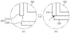
도 4는, 본 발명의 일 실시예에 따른 상부 캔(210)과 하부 밀폐부재(220)의 결합 구성을 개략적으로 나타내는 도면이다. 도 4에서는, 설명의 편의를 위해 도 3의 A 부분을 중심으로 나타내도록 한다.4 is a view schematically showing a combination of an
우선, 도 4의 (a)에 도시된 바와 같이, 상부 캔(210)의 하단은 개방되어 있고, 하부 밀폐부재(220)는 전극 조립체(300)가 삽입된 이후에, 상부 캔(210)의 하단으로 이동하게 된다. 그리고, 하부 밀폐부재(220)가 상부 캔(210)의 하단에 밀착되면, 도 4의 (b)에서 L로 표시된 바와 같이, 상부 캔(210)의 하단과 하부 밀폐부재(220)는 레이저 용접 등의 접합 방법을 통해 서로 결합되어 이 부분은 밀폐될 수 있게 된다.4 (a), the lower end of the
도 4는, 도 3의 전지 케이스(200)에서 좌측 하단 구성에 대해 도시하였으나, 전지케이스의 하단 전체에서 이와 같은 형태의 결합이 이루어질 수 있다.FIG. 4 shows the lower left end structure of the
한편, 도 4에 도시된 상부 캔(210)과 하부 밀폐부재(220)의 결합 형태는 일례에 불과할 뿐, 본 발명이 반드시 이러한 결합 형태로 한정되는 것은 아니며, 다양한 결합 형태가 존재할 수 있다.Meanwhile, the combination of the
바람직하게는, 상기 하부 밀폐부재(220)는 홈이 형성되어 있고, 상부 캔(210)은 이러한 하부 밀폐부재(220)의 홈에 삽입됨으로써, 상부 캔(210)과 하부 밀폐부재(220)가 결합될 수 있다.The
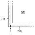
도 5 및 도 6은, 본 발명의 다른 실시예에 따른 상부 캔(210)과 하부 밀폐부재(220)의 결합 구성을 개략적으로 나타내는 도면들이다. 도 5 및 도 6에서도, 설명의 편의를 위해 도 3의 A 부분에 대응되는 부분을 중심으로 나타내도록 한다.5 and 6 are views schematically showing the combination of the
먼저, 도 5에 도시된 바와 같이, 하부 밀폐부재(220)는 그 상부에 홈(221), 즉 오목한 부분이 형성될 수 있다. 이러한 홈(221)은 상부 캔(210)의 하단에 대응되는 형태로 형성될 수 있다. 따라서, 도 5에서 화살표로 표시된 바와 같이, 하부 밀폐부재(220)가 상부 캔(210)의 하단으로 이동하여 밀착될 때, 이러한 홈(221)에 상부 캔(210)의 하단이 삽입되도록 할 수 있다.First, as shown in FIG. 5, the
다만, 이러한 하부 밀폐부재(220)의 홈(221)은 다양하게 형성될 수 있다. 예를 들어, 도 6에 도시된 바와 같이, 하부 밀폐부재(220)의 상단 외주부에 돌출부(222)가 구비되면, 돌출부(222)의 내측은 오목한 부분이 되므로, 이러한 부분 역시 홈이라 할 수 있다. 따라서, 도 6에서 화살표로 표시된 바와 같이, 하부 밀폐부재(220)가 상부 캔(210)의 하단으로 이동하여 밀착될 때, 이러한 홈, 즉 돌출부(222)의 내측에 상부 캔(210)의 하단이 위치하도록 할 수 있다.However, the
특히, 이와 같은 실시예들에 의하면, 상부 캔(210)과 하부 밀폐부재(220)의 좌우 유동을 방지할 수 있어, 상부 캔(210)과 하부 밀폐부재(220)의 결합력을 향상시킬 수 있다.In particular, according to these embodiments, it is possible to prevent lateral movement of the
한편, 도 5 및 도 6에 도시된 바와 같이 상부 캔(210)이 하부 밀폐부재(220)의 홈에 삽입되는 실시예에서도, 상부 캔(210)과 하부 밀폐부재(220)는 서로 레이저 용접될 수 있다.5 and 6, in the embodiment in which the
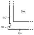
도 7은, 본 발명의 또 다른 실시예에 따른 상부 캔(210)과 하부 밀폐부재(220)의 결합 구성을 개략적으로 나타내는 도면이다.7 is a view schematically showing the combination of the
도 7에 도시된 바와 같이, 하부 밀폐부재(220)는 상부 캔(210)의 하단 내측면에 삽입되게 구성될 수 있다. 그리고, 하부 밀폐부재(220)와 상부 캔(210)은 L로 표시된 바와 같이 레이저 용접에 의해 서로 접합될 수 있다.As shown in FIG. 7, the
이러한 도 4 내지 도 7의 실시예 이외에도, 상부 캔(210)과 하부 밀폐부재(220)의 결합 구성에 대한 실시예는 다양하게 존재할 수 있다.In addition to the embodiments shown in FIGS. 4 to 7, various combinations of the
상기 캡 조립체(100)는, 탑 캡(110), 안전 벤트(120) 및 가스켓(150)을 포함한다. 그리고, 이러한 캡 조립체(100)는, 전지 케이스(200)의 형태에 따라 원형 또는 각형 등 다양한 형태로 형성될 수 있다.The
상기 탑 캡(110)은, 캡 조립체(100)의 최상부에 상부 방향으로 돌출된 형태로 배치되어 양극 단자를 형성한다. 따라서, 상기 탑 캡(110)은 이차 전지가 외부와 전기적으로 접속되도록 한다. 또한, 이러한 탑 캡(110)에는 가스가 배출될 수 있는 가스 구멍이 형성될 수 있다. 따라서, 전극 조립체(300)로부터 가스 발생시 이러한 가스 구멍을 통해 전지 케이스(200) 외부로 가스가 배출되도록 할 수 있다. 상기 탑 캡(110)은, 예를 들어 스테인리스 스틸이나 알루미늄과 같은 금속 재질로 형성될 수 있다.The
상기 안전 벤트(120)는, 상기 탑 캡(110)의 하부에서 탑 캡(110)과 외주면, 즉 테두리 부분이 접촉되도록 배치될 수 있다. 그리고, 이러한 안전 벤트(120)는 이차 전지의 내압, 즉 전지 케이스(200)의 내압이 일정 수준 이상으로 증가하는 경우, 형태가 변형되도록 구성된다. 예를 들어, 상기 안전 벤트(120)는 이차 전지의 내압이 12~25 kgf/cm2일 때 형태가 변형되어 파열되도록 구성될 수 있다.The
이를 위해, 상기 안전 벤트(120)는, 도면에 도시된 바와 같이,중심부가 하부 방향으로 돌출되도록 형성되고, 그러한 중심부 부근에 소정의 노치가 형성될 수 있다. 따라서, 이차 전지의 내부, 즉 전극 조립체(300) 측으로부터 가스가 발생하여 내압이 증가하게 되면, 안전 벤트(120)는 그것의 형상이 역전되면서 상향 돌출되게 되고, 노치들을 중심으로 파열될 수 있다. 따라서, 이러한 안전 벤트(120)의 파열된 부분을 통해 전지 케이스(200)의 내부에 차 있던 가스가 외부로 배출될 수 있게 된다.For this, the
상기 가스켓(150)은, 탑 캡(110) 및 안전 벤트(120)의 테두리를 감싸도록 구성된다. 특히, 상기 가스켓(150)은, 도 3에 도시된 바와 같이, 상부 캔(210)과 탑 캡(110) 및 안전 벤트(120) 사이에 개재될 수 있다. 이러한 가스켓(150)은, 탑 캡(110) 및 안전 벤트(120)의 테두리 부분이 상부 캔(210)과 절연될 수 있도록 하므로, 전기 절연성을 갖는 재질로 이루어질 수 있다. 또한, 상기 가스켓(150)은 캡 조립체(100)를 지지하고 보호하기 위해 내충격성, 탄력성 및 내구성을 가진 재질로 이루어질 수 있다. 따라서, 상기 가스켓(150)은, 예를 들어 폴리올레핀(polyolefine) 또는 폴리프로필렌(PP)으로 제조될 수 있다. 그리고, 상기 가스켓(150)은 전기 절연성이 약화되는 것을 방지하기 위해 열처리에 의하지 않고 기계적 가공에 의해 벤딩되는 것이 좋다.The
특히, 상기 가스켓(150)은, 안전 벤트(120)의 테두리 하단을 상부 방향으로 지지하는 돌출부(151)가 형성될 수 있다. 이러한 가스켓(150)의 돌출부(151)는, 안전 벤트(120) 및 탑 캡(110)이 하부 방향으로 이탈하는 것을 막을 수 있다.Particularly, the
다만, 가스켓(150)은, 이와 같은 돌출부(151)를 구비하지 않을 수 있으며, 이 경우 절곡된 형태 등을 통해 탑 캡(110) 및 안전 벤트(120)를 상부 방향으로 지지할 수도 있다.However, the
바람직하게는, 상기 가스켓(150)은, 도 3의 B 부분에 표시된 바와 같이, 하단부가 전극 조립체(300)의 상면에 접촉되도록 구성될 수 있다. 그리고, 상기 가스켓(150)은 상단부가 상부 캔(210)의 상단 절곡부(211) 내면에 접촉되게 구성될 수 있다. 이러한 실시예에 의하면, 가스켓(150)에 의해 전지 케이스(200) 내부에서 전극 조립체(300)가 유동되는 것, 특히 전극 조립체(300)가 상하부 방향으로 유동되는 것을 방지할 수 있다.Preferably, the
또한 바람직하게는, 본 발명에 따른 이차 전지는, 전극 조립체(300)의 상부에 상부 절연판을 더 포함할 수 있다. 이러한 상부 절연판은, 전기적 절연성을 갖는 재질로 구성되어, 전극 조립체(300)와 캡 조립체(100)를 절연시키는 역할을 할 수 있다.Also, preferably, the secondary battery according to the present invention may further include an upper insulating plate on the upper portion of the
이 경우, 상기 가스켓(150)은, 하단부가 상부 절연판의 상면에 접촉되도록 구성될 수 있다. 그리고, 가스켓(150)은 상단부가 상부 캔(210)의 상단 절곡부(211) 내면에 접촉됨으로써, 전극 조립체(300)의 유동을 방지할 수 있다.In this case, the
또한 바람직하게는, 본 발명에 따른 이차 전지의 캡 조립체(100)는, 도 3에 도시된 바와 같이, 전류차단부재(140)를 더 포함할 수 있다.Also, preferably, the
상기 전류차단부재(140)는, CID(Current Interrupt Device)라고도 불리는데, 안전 벤트(120)와 전극 조립체(300) 사이에 위치하여, 전극 조립체(300)와 안전 벤트(120)가 전기적으로 접속되도록 한다. 즉, 전류차단부재(140)는, 상부의 적어도 일부분이 안전 벤트(120)의 중앙 돌출 부분 하단에 연결되고, 하부가 전극 조립체(300)의 전극 리드, 이를테면 양극 리드(310)와 연결된다. 따라서, 정상적인 상태에서는 전극 조립체(300)로부터 생성된 전류는 양극 리드(310)를 거쳐 전류차단부재(140), 안전 벤트(120) 및 탑 캡(110)으로 흐름으로써 이차 전지의 방전이 이루어질 수 있다. 그러나, 가스 발생으로 전지의 내압이 증가하여 안전 벤트(120)의 형상이 역전되면, 안전 벤트(120)와 전류차단부재(140) 사이의 접촉이 끊어지거나, 전류차단부재(140)가 파손되어, 안전 벤트(120)와 전류차단부재(140) 사이의 전기적 접속은 차단되게 된다.The
이처럼 캡 조립체(100)는 전류차단부재(140)를 포함할 수 있는데, 이 경우, 도 3에 도시된 바와 같이, 절연부재(130)를 더 포함할 수 있다.As such, the
상기 절연부재(130)는, 안전 벤트(120)와 전류차단부재(140) 사이에 개재되어, 안전 벤트(120)의 중앙 돌출 부분과 전류차단부재(140)가 접촉되는 부분을 제외하고는 전류차단부재(140)와 안전 벤트(120)가 서로 전기적으로 절연되도록 한다.The insulating
한편, 도 3에 도시된 캡 조립체(100)의 형태는 일 실시예에 불과할 뿐, 본 발명이 이러한 캡 조립체(100)의 특정 형태로 제한되는 것은 아니다.Meanwhile, the shape of the
일 예로, 본 발명에 따른 이차 전지의 캡 조립체(100)는, 안전 소자(미도시)를 더 포함할 수 있다.For example, the
상기 안전 소자는, 탑 캡(110)과 안전 벤트(120) 사이에 배치되어 탑 캡(110)과 안전 벤트(120)를 전기적으로 연결시킨다. 이러한 안전 소자는, 이차 전지의 온도가 상승하는 경우 전지 내부의 전류 흐름을 차단할 수 있는데, 이를테면 PTC(Positive Temperature Coefficient element) 소자로 형성될 수 있다.The safety element is disposed between the
본 발명에 따른 배터리 팩은 상술한 이차 전지를 하나 이상 포함한다. 그리고, 이러한 배터리 팩은, 상술한 이차 전지 이외에도, 충방전 동작을 제어하기 위해 BMS(Battery Management System)와 같은 배터리 관리 장치를 포함할 수 있다.The battery pack according to the present invention includes at least one secondary battery described above. Such a battery pack may include a battery management device such as a battery management system (BMS) for controlling charging and discharging operations in addition to the above-described secondary battery.
도 8은, 본 발명의 일 실시예에 따른 비딩부가 형성되지 않은 이차 전지를 제조하는 방법을 개략적으로 나타내는 흐름도이다.FIG. 8 is a flowchart schematically showing a method of manufacturing a secondary battery in which a beading portion is not formed according to an embodiment of the present invention.
도 8을 참조하면, 본 발명에 따라 이차 전지를 제조하기 위해서는, 먼저 양극판 및 음극판이 세퍼레이터를 사이에 두고 배치된 전극 조립체(300)를 준비하고(S110), 상부 캔(210) 및 하부 밀폐부재(220)를 포함하는 전지 케이스(200)를 준비한다(S120). 그리고, 탑 캡(110), 안전 벤트(120) 및 가스켓(150)을 포함하는 캡 조립체(100)도 준비한다(S130).Referring to FIG. 8, in order to manufacture a secondary battery according to the present invention, an
여기서, 상기 S120 단계에서 마련되는 전지 케이스(200)에서, 상부 캔(210)은 전극 조립체(300) 및 전해액을 수납 가능하도록 내부 공간이 형성되어 있고, 상단 및 하단은 개방되어 있으며, 특히 상단은 내측 방향으로 절곡되어 있다. 그리고, 상기 S120 단계에서는, 상기 전지 케이스(200)의 하부 밀폐부재(220)가 상부 캔(210)과 별도로 분리된 상태로 구비된다. 따라서, 상기 상부 캔(210)의 하단은 개방 상태로 있게 된다. 한편, 상기 상부 캔(210)은 원통형일 수 있으나, 본 발명이 반드시 이러한 상부 캔(210) 형태로 제한되는 것은 아니다.In the
또한, 상기 S130 단계에서 마련되는 캡 조립체(100)에서, 탑 캡(110)은 이차 전지의 최상부에 돌출된 형태로 배치되어 양극 단자를 형성하고, 안전 벤트(120)는 탑 캡(110)의 하부에서 전지 케이스(200)의 내압 증가시 형태가 변형되며, 가스켓(150)은 탑 캡(110) 및 안전 벤트(120)의 테두리들을 감싸도록 구성된다.In addition, in the
한편, 도 8에서는, 상기 S110 단계, S120 단계 및 S130 단계가, 순차적으로 수행된 것처럼 도시되어 있으나, 이는 설명의 편의를 위한 것일 뿐, 상기 S110 단계, S120 단계 및 S130 단계는 서로 순서가 바뀌거나 동시에 수행되어도 무방하다.8, steps S110, S120, and S130 are illustrated as being sequentially performed. However, the steps S110, S120, and S130 may be performed in the order of It may be performed at the same time.
이처럼, 전극 조립체(300), 전지 케이스(200) 및 캡 조립체(100)가 준비되면, 다음으로, 가스켓(150)의 상단부가 상부 캔(210)의 절곡된 상부 내면에 접촉되도록, 캡 조립체(100)를 상부 캔(210)의 하단 개방부를 통하여 삽입한다(S140).When the
그리고, 캡 조립체(100)의 하부에 위치하도록 전극 조립체(300)를 상부 캔(210)의 하단 개방부를 통하여 상부 방향으로 상부 캔(210)에 삽입한다(S150).The
그리고 나서, 상부 캔(210)의 하단 개방부가 밀폐될 수 있도록 하부 밀폐부재(220)를 상부 캔(210)의 하단에 결합한다(S160).Then, the
바람직하게는, 상기 S150 단계는, 도 3의 B 부분에 표시된 바와 같이, 전극 조립체(300)의 상면이 가스켓(150)의 하단부에 접촉되도록 전극 조립체(300)를 삽입하는 것이 좋다.3, it is preferable that the
또한, 상기 S110 단계는, 전극 조립체(300)의 상부에 상부 절연판을 더 구비하도록 할 수 있는데, 이 경우, 상기 S150 단계는, 상부 절연판의 상면이 가스켓(150)의 하단부에 접촉되도록 전극 조립체(300)를 삽입하는 것이 바람직하다.In addition, the step S110 may further include an upper insulating plate on the upper part of the
또한 바람직하게는, 상기 S160 단계는, 레이저 용접에 의해 하부 밀폐부재(220)가 상부 캔(210)의 하단에 결합되도록 수행될 수 있다.Also, preferably, the step S160 may be performed such that the
또한 바람직하게는, 상기 S160 단계는, 상부 캔(210)이 하부 밀폐부재(220)의 홈에 삽입되는 형태로 수행될 수 있다. 이를 위해, 상기 S120 단계는, 상부 캔(210)의 하단이 삽입될 수 있도록 하부 밀폐부재(220)에 홈이 형성된 전지 케이스(200)를 준비할 수 있다.Also, preferably, the step S160 may be performed such that the
또한 바람직하게는, 상기 S130 단계는, 상부가 안전 벤트(120)의 하단에 연결되고 하부가 전극 조립체(300)와 연결될 수 있는 전류차단부재(140) 및 안전 벤트(120)와 전류차단부재(140) 사이에 개재되어 일부분을 제외하고는 전류차단부재(140)를 안전 벤트(120)와 전기적으로 절연시키는 절연부재(130)가 캡 조립체(100)에 더 포함되도록 할 수 있다.In addition, preferably, the step S130 includes a
또한 바람직하게는, 상기 S130 단계는, 탑 캡(110)과 안전 벤트(120) 사이에 배치되어, 온도 상승시 전류를 차단하는 안전 소자가 캡 조립체(100)에 더 포함되도록 할 수 있다.
The
이상과 같이, 본 발명은 비록 한정된 실시예와 도면에 의해 설명되었으나, 본 발명은 이것에 의해 한정되지 않으며 본 발명이 속하는 기술분야에서 통상의 지식을 가진 자에 의해 본 발명의 기술사상과 아래에 기재될 특허청구범위의 균등범위 내에서 다양한 수정 및 변형이 가능함은 물론이다.While the present invention has been particularly shown and described with reference to exemplary embodiments thereof, it is to be understood that the invention is not limited to the disclosed exemplary embodiments. It will be understood that various modifications and changes may be made without departing from the scope of the appended claims.
한편, 본 명세서에서는. 상, 하, 좌, 우 등과 같이 방향을 나타내는 용어가 사용되었으나, 이러한 용어는 설명의 편의를 위한 것일 뿐, 관측자의 보는 위치나 대상의 놓여져 있는 위치 등에 따라 다르게 표현될 수 있음은 본 발명의 당업자에게 자명하다.On the other hand, in the present specification. It is to be understood that the terminology such as up, down, left, right, etc., is used for convenience of explanation, but can be expressed differently depending on the viewing position of the observer or the position of the object. To be clear to.
100: 캡 조립체
110: 탑 캡
120: 안전 벤트
130: 절연부재
140: 전류차단부재
150: 가스켓
200: 전지 케이스
210: 상부 캔
220: 하부 밀폐부재
300: 전극 조립체
310: 양극 리드
320: 음극 리드100: cap assembly
110: Top cap
120: Safety vent
130: Insulation member
140: current blocking member
150: Gasket
200: Battery case
210: upper can
220: Lower sealing member
300: electrode assembly
310: positive lead
320: cathode lead
Claims (17)
Translated fromKorean양극판 및 음극판이 세퍼레이터를 사이에 두고 배치된 전극 조립체;
내부 공간에 상기 전극 조립체 및 전해액을 수납하고 상단 및 하단이 개방되어 있으며 상단이 내측 방향으로 절곡된 상부 캔 및 상기 상부 캔의 하단에 결합되어 하단을 밀폐시키는 하부 밀폐부재를 포함하는 전지 케이스; 및
최상부에 돌출된 형태로 배치되어 양극 단자를 형성하는 탑 캡, 상기 탑 캡의 하부에서 상기 전지 케이스의 내압 증가시 형태가 변형되는 안전 벤트, 및 상기 탑 캡 및 상기 안전 벤트의 테두리들을 감싸는 가스켓을 포함하는 캡 조립체
를 포함하여,
상기 가스켓은 상단부가 상기 상부 캔의 상단 절곡부 내면에 접촉되고, 하단부가 상기 전극 조립체의 상면에 접촉되어, 상기 캡 조립체에 대한 용접없이 상기 캡 조립체 및 전극 조립체의 유동이 방지되는 것을 특징으로 하는 이차 전지.In the secondary battery in which the beading portion is not formed,
An electrode assembly in which a positive electrode plate and a negative electrode plate are disposed with a separator interposed therebetween;
A battery case including an upper can accommodating the electrode assembly and an electrolyte solution in an inner space and having an upper end and a lower end opened and an upper end bent in the inner direction and a lower sealing member coupled to a lower end of the upper can to seal the lower end; And
A top cap which is disposed in a protruding shape at an uppermost portion to form a positive terminal, a safety vent which is deformed when the internal pressure of the battery case is increased at the lower portion of the top cap, and a gasket which surrounds the rims of the top cap and the safety vent The cap assembly
Including,
Wherein the upper end of the gasket is in contact with the inner surface of the upper bent portion of the upper can and the lower end of the gasket is in contact with the upper surface of the electrode assembly to prevent the cap assembly and the electrode assembly from flowing without welding to the cap assembly. Secondary battery.
상기 전극 조립체의 상부에 상부 절연판을 더 포함하고,
상기 가스켓은, 상단부가 상기 상부 캔의 상단 절곡부 내면에 접촉되고, 하단부가 상기 상부 절연판의 상면에 접촉되는 것을 특징으로 하는 이차 전지.The method according to claim 1,
Further comprising an upper insulating plate on an upper portion of the electrode assembly,
Wherein the upper end of the gasket is in contact with the inner surface of the upper bent portion of the upper can, and the lower end of the gasket is in contact with the upper surface of the upper insulating plate.
상기 상부 캔과 상기 하부 밀폐부재는, 레이저 용접에 의해 결합된 것을 특징으로 하는 이차 전지.The method according to claim 1,
Wherein the upper can and the lower closure member are coupled by laser welding.
상기 하부 밀폐부재는 홈이 형성되어 있고, 상기 상부 캔은 상기 하부 밀폐부재의 홈에 삽입되는 것을 특징으로 하는 이차 전지.The method according to claim 1,
Wherein the lower sealing member is formed with a groove, and the upper can is inserted into the groove of the lower sealing member.
상부가 상기 안전 벤트의 하단에 연결되고, 하부가 전극 조립체와 연결될 수 있는 전류차단부재; 및 상기 안전 벤트와 상기 전류차단부재 사이에 개재되어 일부분을 제외하고는 상기 전류차단부재를 상기 안전 벤트와 전기적으로 절연시키는 절연부재를 더 포함하는 것을 특징으로 하는 이차 전지.The method according to claim 1,
A current blocking member whose upper portion is connected to the lower end of the safety vent and whose lower portion can be connected to the electrode assembly; And an insulating member interposed between the safety vent and the current blocking member to electrically isolate the current blocking member from the safety vent, except for a part thereof.
상기 탑 캡과 상기 안전 벤트 사이에 배치되어, 온도 상승시 전류를 차단하는 안전 소자를 더 포함하는 것을 특징으로 하는 이차 전지.The method according to claim 1,
Further comprising a safety element disposed between the top cap and the safety vent to shut off current when the temperature rises.
상기 상부 캔은, 원통형으로 형성된 것을 특징으로 하는 이차 전지.The method according to claim 1,
Wherein the upper can is formed in a cylindrical shape.
양극판 및 음극판이 세퍼레이터를 사이에 두고 배치된 전극 조립체를 준비하는 단계;
상기 전극 조립체 및 전해액을 수납 가능하도록 내부 공간이 형성되고 상단 및 하단이 개방되어 상단이 내측 방향으로 절곡된 상부 캔 및 상기 상부 캔과 분리된 하부 밀폐부재를 포함하는 전지 케이스를 준비하는 단계;
최상부에 돌출된 형태로 배치되어 양극 단자를 형성하는 탑 캡, 상기 탑 캡의 하부에서 상기 전지 케이스의 내압 증가시 형태가 변형되는 안전 벤트, 및 상기 탑 캡 및 상기 안전 벤트의 테두리들을 감싸는 가스켓을 포함하는 캡 조립체를 준비하는 단계;
상기 가스켓의 상단부가 상기 상부 캔의 절곡된 상부 내면에 접촉되도록 상기 캡 조립체를 상기 상부 캔의 하단 개방부를 통하여 상부 방향으로 삽입하는 단계;
상기 캡 조립체의 하부에 위치하도록 상기 전극 조립체를 상기 상부 캔의 하단 개방부를 통하여 상부 방향으로 삽입하는 단계; 및
상기 상부 캔의 하단을 밀폐시키도록 상기 하부 밀폐부재를 상기 상부 캔의 하단에 결합하는 단계
를 포함하여,
상기 가스켓은 상단부가 상기 상부 캔의 상단 절곡부 내면에 접촉되고, 하단부가 상기 전극 조립체의 상면에 접촉되어, 상기 캡 조립체에 대한 용접없이 상기 캡 조립체 및 전극 조립체의 유동이 방지되는 것을 특징으로 하는 이차 전지 제조 방법.A method of manufacturing a secondary battery in which a bead portion is not formed,
Preparing an electrode assembly in which a positive electrode plate and a negative electrode plate are disposed with a separator interposed therebetween;
Preparing a battery case including an upper can and an upper can, wherein an upper space and an upper space are opened to accommodate the electrode assembly and the electrolyte, and an upper end is bent in an inner direction;
A top cap which is disposed in a protruding shape at an uppermost portion to form a positive terminal, a safety vent which is deformed when the internal pressure of the battery case is increased at the lower portion of the top cap, and a gasket which surrounds the rims of the top cap and the safety vent Preparing a cap assembly comprising the cap assembly;
Inserting the cap assembly in an upper direction through a lower end opening of the upper can such that an upper end of the gasket is in contact with a curved upper inner surface of the upper can;
Inserting the electrode assembly in an upper direction through a lower end opening of the upper can so as to be positioned below the cap assembly; And
Coupling the lower closure member to the lower end of the upper can to seal the lower end of the upper can;
Including,
Wherein the upper end of the gasket is in contact with the inner surface of the upper bent portion of the upper can and the lower end of the gasket is in contact with the upper surface of the electrode assembly to prevent the cap assembly and the electrode assembly from flowing without welding to the cap assembly. A method for manufacturing a secondary battery.
상기 전극 조립체의 준비 단계는, 상기 전극 조립체의 상부에 상부 절연판을 더 구비하고,
상기 전극 조립체의 삽입 단계는, 상기 상부 절연판의 상면이 상기 가스켓의 하단부에 접촉되도록 상기 전극 조립체를 삽입하는 것을 특징으로 하는 이차 전지 제조 방법.11. The method of claim 10,
The preparing of the electrode assembly may further include an upper insulating plate on the electrode assembly,
Wherein the step of inserting the electrode assembly inserts the electrode assembly such that the upper surface of the upper insulating plate contacts the lower end of the gasket.
상기 하부 밀폐부재와 상부 캔의 결합 단계에서, 상기 하부 밀폐부재는 레이저 용접에 의해 상기 상부 캔의 하단에 결합되는 것을 특징으로 하는 이차 전지 제조 방법.11. The method of claim 10,
Wherein the lower sealing member is coupled to the lower end of the upper can by laser welding in the step of joining the lower sealing member and the upper can.
상기 하부 밀폐부재와 상부 캔의 결합 단계에서, 상기 상부 캔은 상기 하부 밀폐부재의 홈에 삽입되는 것을 특징으로 하는 이차 전지 제조 방법.11. The method of claim 10,
Wherein the upper can is inserted into the groove of the lower closure member in the step of engaging the upper closure member with the upper closure member.
상기 캡 조립체의 준비 단계는, 상기 캡 조립체에 상부가 상기 안전 벤트의 하단에 연결되고, 하부가 전극 조립체와 연결될 수 있는 전류차단부재 및 상기 안전 벤트와 상기 전류차단부재 사이에 개재되어 일부분을 제외하고는 상기 전류차단부재를 상기 안전 벤트와 전기적으로 절연시키는 절연부재가 더 포함되도록 하는 것을 특징으로 하는 이차 전지 제조 방법.11. The method of claim 10,
The preparation of the cap assembly may include a current blocking member having an upper portion connected to the lower end of the safety vent and a lower portion connected to the electrode assembly, and a current blocking member interposed between the safety vent and the current blocking member, And an insulating member electrically insulating the current blocking member from the safety vent.
상기 캡 조립체의 준비 단계는, 상기 캡 조립체에 상기 탑 캡과 상기 안전 벤트 사이에 배치되어, 온도 상승시 전류를 차단하는 안전 소자가 더 포함되도록 하는 것을 특징으로 하는 이차 전지 제조 방법.11. The method of claim 10,
Wherein the step of preparing the cap assembly further comprises a safety element disposed between the top cap and the safety vent in the cap assembly to block current when the temperature rises.
상기 상부 캔은, 원통형인 것을 특징으로 하는 이차 전지 제조 방법.11. The method of claim 10,
Wherein the upper can has a cylindrical shape.
Priority Applications (7)
| Application Number | Priority Date | Filing Date | Title |
|---|---|---|---|
| KR1020130020744AKR101514827B1 (en) | 2013-02-26 | 2013-02-26 | Secondary battery and method for manufacturing the same |
| PCT/KR2014/001232WO2014133275A1 (en) | 2013-02-26 | 2014-02-14 | Secondary battery and manufacturing method therefor |
| EP14757062.6AEP2822060B1 (en) | 2013-02-26 | 2014-02-14 | Secondary battery and manufacturing method therefor |
| CN201480001073.0ACN104285314B (en) | 2013-02-26 | 2014-02-14 | Secondary battery and manufacturing method therefor |
| JP2015534405AJP6022696B2 (en) | 2013-02-26 | 2014-02-14 | Secondary battery and manufacturing method thereof |
| TW103106065ATWI489676B (en) | 2013-02-26 | 2014-02-24 | Secondary battery and method of manufacturing same |
| US14/491,023US9843025B2 (en) | 2013-02-26 | 2014-09-19 | Secondary battery and method for manufacturing the same |
Applications Claiming Priority (1)
| Application Number | Priority Date | Filing Date | Title |
|---|---|---|---|
| KR1020130020744AKR101514827B1 (en) | 2013-02-26 | 2013-02-26 | Secondary battery and method for manufacturing the same |
Publications (2)
| Publication Number | Publication Date |
|---|---|
| KR20140106327A KR20140106327A (en) | 2014-09-03 |
| KR101514827B1true KR101514827B1 (en) | 2015-04-23 |
Family
ID=51428495
Family Applications (1)
| Application Number | Title | Priority Date | Filing Date |
|---|---|---|---|
| KR1020130020744AActiveKR101514827B1 (en) | 2013-02-26 | 2013-02-26 | Secondary battery and method for manufacturing the same |
Country Status (7)
| Country | Link |
|---|---|
| US (1) | US9843025B2 (en) |
| EP (1) | EP2822060B1 (en) |
| JP (1) | JP6022696B2 (en) |
| KR (1) | KR101514827B1 (en) |
| CN (1) | CN104285314B (en) |
| TW (1) | TWI489676B (en) |
| WO (1) | WO2014133275A1 (en) |
Cited By (4)
| Publication number | Priority date | Publication date | Assignee | Title |
|---|---|---|---|---|
| WO2018124532A3 (en)* | 2016-12-27 | 2018-08-23 | 주식회사 엘지화학 | Cylindrical-battery-cell cap assembly having current interrupt device and safety vent coupled to each other by electrical insulating material |
| WO2022177371A1 (en)* | 2021-02-19 | 2022-08-25 | 주식회사 엘지에너지솔루션 | Battery, and battery pack and vehicle comprising same |
| WO2025053660A1 (en)* | 2023-09-06 | 2025-03-13 | 주식회사 엘지에너지솔루션 | Secondary battery and method for manufacturing secondary battery |
| US12407027B2 (en) | 2021-02-19 | 2025-09-02 | Lg Energy Solution, Ltd. | Battery and current collector applied thereto, and battery pack and vehicle including the battery |
Families Citing this family (25)
| Publication number | Priority date | Publication date | Assignee | Title |
|---|---|---|---|---|
| JP6490053B2 (en)* | 2014-03-28 | 2019-03-27 | 三洋電機株式会社 | Cylindrical sealed battery and battery pack |
| US10340483B2 (en) | 2014-08-26 | 2019-07-02 | Cps Technology Holdings Llc | Welding process for sealing a battery module |
| KR102567831B1 (en) | 2015-10-02 | 2023-08-17 | 삼성에스디아이 주식회사 | Secondary battery |
| KR102263435B1 (en)* | 2017-09-13 | 2021-06-11 | 주식회사 엘지에너지솔루션 | Cylindrical Battery Cell Having no Beading Part |
| KR102275779B1 (en) | 2017-11-17 | 2021-07-13 | 주식회사 엘지에너지솔루션 | Secondary battery |
| CN111566846B (en)* | 2017-12-13 | 2022-10-21 | 三星Sdi株式会社 | Secondary battery |
| CN117254223A (en)* | 2018-01-03 | 2023-12-19 | 宁德时代新能源科技股份有限公司 | Secondary battery and automobile |
| JP7093199B2 (en)* | 2018-02-16 | 2022-06-29 | Fdk株式会社 | Seal and battery |
| CN111902960B (en)* | 2018-04-06 | 2022-12-27 | 三洋电机株式会社 | Battery with a battery cell |
| WO2019194227A1 (en)* | 2018-04-06 | 2019-10-10 | 三洋電機株式会社 | Cell |
| JPWO2019194253A1 (en)* | 2018-04-06 | 2021-04-01 | 三洋電機株式会社 | battery |
| JP7312743B2 (en) | 2018-04-06 | 2023-07-21 | パナソニックエナジー株式会社 | battery |
| KR102323809B1 (en) | 2018-06-18 | 2021-11-09 | 주식회사 엘지에너지솔루션 | The Apparatus For Venting And The Method For Manufacturing Thereof |
| US10804515B2 (en)* | 2018-08-08 | 2020-10-13 | Duracell U.S. Operations, Inc. | Batteries having vents |
| CN109860448A (en)* | 2019-01-03 | 2019-06-07 | 王生义 | A kind of cap assemblies and battery for battery |
| CN110880564A (en)* | 2019-10-28 | 2020-03-13 | 宜兴市惠华复合材料有限公司 | Novel lithium battery shell and shell cover applying same |
| US20230098011A1 (en)* | 2020-03-09 | 2023-03-30 | Sanyo Electric Co., Ltd. | Hermetically sealed battery |
| KR102754515B1 (en)* | 2021-04-08 | 2025-01-13 | 주식회사 엘지에너지솔루션 | Secondary battery and manufacturing method of the same |
| CN113328213B (en)* | 2021-04-27 | 2023-07-11 | 宁波超霸能源有限公司 | Manufacturing method of cylindrical lithium battery |
| CN113675510B (en)* | 2021-08-17 | 2023-01-24 | 厦门海辰储能科技股份有限公司 | The end connection structure of the battery cell, the battery cell, and the power battery |
| EP4199241A4 (en)* | 2021-09-16 | 2024-11-06 | Contemporary Amperex Technology (Hong Kong) Limited | BATTERY CELL, BATTERY, ELECTRIC DEVICE, AND MANUFACTURING METHOD AND SYSTEM FOR BATTERY CELL |
| DE102022101673A1 (en)* | 2022-01-25 | 2023-07-27 | Bayerische Motoren Werke Aktiengesellschaft | Battery cell housing for a battery cell of an electrical energy store and battery cell |
| SE546550C2 (en)* | 2022-08-31 | 2024-11-26 | Northvolt Ab | A cylindrical secondary cell comprising a reduced radius enclosure and a lid |
| SE546549C2 (en)* | 2022-08-31 | 2024-11-26 | Northvolt Ab | A cylindrical secondary cell comprising an enclosure with a brim and a lid with a flange |
| SE546548C2 (en)* | 2022-08-31 | 2024-11-26 | Northvolt Ab | A cylindrical secondary cell comprising an inclined enclosure and a lid |
Citations (1)
| Publication number | Priority date | Publication date | Assignee | Title |
|---|---|---|---|---|
| WO2013025078A2 (en)* | 2011-08-18 | 2013-02-21 | 주식회사 엘지화학 | Method for manufacturing a secondary battery |
Family Cites Families (33)
| Publication number | Priority date | Publication date | Assignee | Title |
|---|---|---|---|---|
| JPS578619Y2 (en)* | 1976-09-14 | 1982-02-18 | ||
| JPS5341622A (en) | 1976-09-27 | 1978-04-15 | Honda Motor Co Ltd | Piston made of fiber-reinforced light alloy |
| JPS54144222U (en)* | 1978-03-31 | 1979-10-06 | ||
| JPS54144222A (en) | 1978-04-28 | 1979-11-10 | Iwasaki Kosei | Pusheddout writing implement |
| US5626983A (en)* | 1994-07-13 | 1997-05-06 | Rayovac Corporation | Zinc anode for reduced environmental hazard LeClanche cell having improved performance |
| CA2131777A1 (en)* | 1994-09-09 | 1996-03-10 | Allen Shkuratoff | Sealed electrical device with unitary fill port and terminal construction |
| JPH11283586A (en)* | 1998-03-31 | 1999-10-15 | Sanyo Electric Co Ltd | Battery and its manufacture |
| US6410186B1 (en)* | 1998-08-21 | 2002-06-25 | Eveready Battery Company, Inc. | Battery construction having double seam cover closure |
| US6265096B1 (en)* | 1998-08-21 | 2001-07-24 | Eveready Battery Company, Inc. | Electrochemical cell having collector electrically insulated from cover |
| JP2003142043A (en)* | 2001-07-09 | 2003-05-16 | Hitachi Maxell Ltd | Battery |
| US7070881B2 (en)* | 2001-10-18 | 2006-07-04 | Quallion Llc | Electrical battery assembly and method of manufacture |
| JP2004071265A (en)* | 2002-08-05 | 2004-03-04 | Sanyo Electric Co Ltd | Battery |
| JP4356314B2 (en)* | 2002-12-20 | 2009-11-04 | パナソニック株式会社 | Battery and battery pack |
| JP4567374B2 (en) | 2003-08-28 | 2010-10-20 | パナソニック株式会社 | Battery and manufacturing method thereof |
| TWI318016B (en)* | 2003-12-09 | 2009-12-01 | Hon Hai Prec Ind Co Ltd | Cap assembly for nonaqueous electrolyte battery |
| KR100670526B1 (en)* | 2005-03-09 | 2007-01-16 | 삼성에스디아이 주식회사 | Cylindrical Secondary Battery and Formation Method |
| JP5198723B2 (en)* | 2005-06-13 | 2013-05-15 | 冨士発條株式会社 | Sealing plate for sealed battery |
| JP2007179793A (en)* | 2005-12-27 | 2007-07-12 | Denso Corp | Cover for sealed battery |
| JP2010505219A (en)* | 2006-09-29 | 2010-02-18 | シェンツェン・ビーエイケイ・バッテリー・カンパニー・リミテッド | Battery core case and battery core |
| CN101611507A (en)* | 2006-12-05 | 2009-12-23 | 文承子 | Cylindrical cell and manufacture method thereof |
| CN101257098B (en)* | 2007-03-02 | 2012-01-25 | 深圳市比克电池有限公司 | Battery and battery seal component convenient for assembling |
| CN101257099A (en)* | 2007-03-02 | 2008-09-03 | 深圳市比克电池有限公司 | Battery sealing components and batteries |
| JP5264099B2 (en) | 2007-04-12 | 2013-08-14 | パナソニック株式会社 | Nonaqueous electrolyte secondary battery |
| JP2009181776A (en)* | 2008-01-30 | 2009-08-13 | Toyota Motor Corp | Sealed battery |
| KR100917742B1 (en)* | 2008-03-13 | 2009-09-15 | 삼성에스디아이 주식회사 | Cylindrical secondary battery |
| JP4446205B2 (en)* | 2008-04-14 | 2010-04-07 | トヨタ自動車株式会社 | Battery and manufacturing method thereof |
| JP2009289637A (en)* | 2008-05-30 | 2009-12-10 | Toyota Motor Corp | Sealed battery and manufacturing method therefor |
| CN102150299B (en)* | 2009-05-25 | 2014-05-28 | 丰田自动车株式会社 | Secondary battery, battery pack, and vehicle and apparatus having the battery pack mounted thereon |
| KR101097255B1 (en)* | 2009-11-30 | 2011-12-21 | 삼성에스디아이 주식회사 | Secondary battery |
| KR20110066448A (en)* | 2009-12-11 | 2011-06-17 | 삼성에스디아이 주식회사 | Lithium secondary battery |
| US8501333B2 (en) | 2010-10-21 | 2013-08-06 | Lg Chem, Ltd. | Cap assembly and secondary battery using the same |
| KR101184403B1 (en)* | 2010-10-21 | 2012-09-19 | 주식회사 엘지화학 | Cap assembly and secondary battery using the same |
| KR101281038B1 (en) | 2010-12-07 | 2013-07-09 | 주식회사 엘지화학 | Cap assembly and secondary battery using the same |
- 2013
- 2013-02-26KRKR1020130020744Apatent/KR101514827B1/enactiveActive
- 2014
- 2014-02-14CNCN201480001073.0Apatent/CN104285314B/enactiveActive
- 2014-02-14JPJP2015534405Apatent/JP6022696B2/enactiveActive
- 2014-02-14WOPCT/KR2014/001232patent/WO2014133275A1/ennot_activeCeased
- 2014-02-14EPEP14757062.6Apatent/EP2822060B1/enactiveActive
- 2014-02-24TWTW103106065Apatent/TWI489676B/enactive
- 2014-09-19USUS14/491,023patent/US9843025B2/enactiveActive
Patent Citations (1)
| Publication number | Priority date | Publication date | Assignee | Title |
|---|---|---|---|---|
| WO2013025078A2 (en)* | 2011-08-18 | 2013-02-21 | 주식회사 엘지화학 | Method for manufacturing a secondary battery |
Cited By (4)
| Publication number | Priority date | Publication date | Assignee | Title |
|---|---|---|---|---|
| WO2018124532A3 (en)* | 2016-12-27 | 2018-08-23 | 주식회사 엘지화학 | Cylindrical-battery-cell cap assembly having current interrupt device and safety vent coupled to each other by electrical insulating material |
| WO2022177371A1 (en)* | 2021-02-19 | 2022-08-25 | 주식회사 엘지에너지솔루션 | Battery, and battery pack and vehicle comprising same |
| US12407027B2 (en) | 2021-02-19 | 2025-09-02 | Lg Energy Solution, Ltd. | Battery and current collector applied thereto, and battery pack and vehicle including the battery |
| WO2025053660A1 (en)* | 2023-09-06 | 2025-03-13 | 주식회사 엘지에너지솔루션 | Secondary battery and method for manufacturing secondary battery |
Also Published As
| Publication number | Publication date |
|---|---|
| US20150004446A1 (en) | 2015-01-01 |
| JP6022696B2 (en) | 2016-11-09 |
| WO2014133275A1 (en) | 2014-09-04 |
| US9843025B2 (en) | 2017-12-12 |
| EP2822060A4 (en) | 2015-09-09 |
| EP2822060B1 (en) | 2017-05-31 |
| KR20140106327A (en) | 2014-09-03 |
| CN104285314B (en) | 2017-02-22 |
| JP2015534232A (en) | 2015-11-26 |
| EP2822060A1 (en) | 2015-01-07 |
| TWI489676B (en) | 2015-06-21 |
| TW201503467A (en) | 2015-01-16 |
| CN104285314A (en) | 2015-01-14 |
Similar Documents
| Publication | Publication Date | Title |
|---|---|---|
| KR101514827B1 (en) | Secondary battery and method for manufacturing the same | |
| EP2626925B1 (en) | Cap assembly and second battery using same | |
| KR101772415B1 (en) | Cap assembly and secondary battery including the same | |
| KR20080049547A (en) | Cylindrical secondary battery | |
| KR20040022716A (en) | Cylindrical type lithium secondary battery and the fabrication method of the same | |
| KR101523064B1 (en) | Cap assembly and secondary battery including the same | |
| KR101549174B1 (en) | Secondary battery and method for manufacturing the same | |
| KR20140106329A (en) | Cap assembly and secondary battery including the same | |
| KR101511302B1 (en) | Secondary battery | |
| KR101121205B1 (en) | Secondary battery | |
| KR20140106326A (en) | Cap assembly and secondary battery including the same | |
| KR102761907B1 (en) | Secondary Battery | |
| KR20120052586A (en) | Cap assembly and secondary battery using the same | |
| KR101446153B1 (en) | Cap assembly for secondary battery, secondary battery using the same, and method for manufacturing the secondary battery | |
| KR101453783B1 (en) | Cap assembly and secondary battery using the same | |
| KR101453782B1 (en) | Secondary battery and method for manufacturing the same | |
| KR101473392B1 (en) | Secondary battery and method for manufacturing the same | |
| KR20150051516A (en) | Cap assembly and secondary battery comprising the same | |
| KR101563680B1 (en) | Secondary battery | |
| KR101279408B1 (en) | Method for manufacturing secondary battery | |
| KR20140082270A (en) | Secondary battery and battery pack including the same | |
| KR20160015771A (en) | A sylnder type battery having enhanced vibration resistant property | |
| KR20130052407A (en) | Secondary battery and method for manufacturing the same |
Legal Events
| Date | Code | Title | Description |
|---|---|---|---|
| PA0109 | Patent application | Patent event code:PA01091R01D Comment text:Patent Application Patent event date:20130226 | |
| A201 | Request for examination | ||
| PA0201 | Request for examination | Patent event code:PA02012R01D Patent event date:20140228 Comment text:Request for Examination of Application Patent event code:PA02011R01I Patent event date:20130226 Comment text:Patent Application | |
| PG1501 | Laying open of application | ||
| E902 | Notification of reason for refusal | ||
| PE0902 | Notice of grounds for rejection | Comment text:Notification of reason for refusal Patent event date:20150119 Patent event code:PE09021S01D | |
| E701 | Decision to grant or registration of patent right | ||
| PE0701 | Decision of registration | Patent event code:PE07011S01D Comment text:Decision to Grant Registration Patent event date:20150328 | |
| GRNT | Written decision to grant | ||
| PR0701 | Registration of establishment | Comment text:Registration of Establishment Patent event date:20150417 Patent event code:PR07011E01D | |
| PR1002 | Payment of registration fee | Payment date:20150417 End annual number:3 Start annual number:1 | |
| PG1601 | Publication of registration | ||
| FPAY | Annual fee payment | Payment date:20180403 Year of fee payment:4 | |
| PR1001 | Payment of annual fee | Payment date:20180403 Start annual number:4 End annual number:4 | |
| FPAY | Annual fee payment | Payment date:20190401 Year of fee payment:5 | |
| PR1001 | Payment of annual fee | Payment date:20190401 Start annual number:5 End annual number:5 | |
| PR1001 | Payment of annual fee | Payment date:20200416 Start annual number:6 End annual number:6 | |
| PR1001 | Payment of annual fee | Payment date:20210413 Start annual number:7 End annual number:7 | |
| PR1001 | Payment of annual fee | Payment date:20230323 Start annual number:9 End annual number:9 | |
| PR1001 | Payment of annual fee | Payment date:20240319 Start annual number:10 End annual number:10 |