KR101514464B1 - Fuel injection system having high-pressure pumps with magnetically operative suction valve - Google Patents
Fuel injection system having high-pressure pumps with magnetically operative suction valveDownload PDFInfo
- Publication number
- KR101514464B1 KR101514464B1KR1020090092934AKR20090092934AKR101514464B1KR 101514464 B1KR101514464 B1KR 101514464B1KR 1020090092934 AKR1020090092934 AKR 1020090092934AKR 20090092934 AKR20090092934 AKR 20090092934AKR 101514464 B1KR101514464 B1KR 101514464B1
- Authority
- KR
- South Korea
- Prior art keywords
- pump
- pressure
- fuel
- storage tank
- suction
- Prior art date
- Legal status (The legal status is an assumption and is not a legal conclusion. Google has not performed a legal analysis and makes no representation as to the accuracy of the status listed.)
- Active
Links
Images
Classifications
- F—MECHANICAL ENGINEERING; LIGHTING; HEATING; WEAPONS; BLASTING
- F02—COMBUSTION ENGINES; HOT-GAS OR COMBUSTION-PRODUCT ENGINE PLANTS
- F02M—SUPPLYING COMBUSTION ENGINES IN GENERAL WITH COMBUSTIBLE MIXTURES OR CONSTITUENTS THEREOF
- F02M59/00—Pumps specially adapted for fuel-injection and not provided for in groups F02M39/00 -F02M57/00, e.g. rotary cylinder-block type of pumps
- F02M59/20—Varying fuel delivery in quantity or timing
- F02M59/36—Varying fuel delivery in quantity or timing by variably-timed valves controlling fuel passages to pumping elements or overflow passages
- F02M59/366—Valves being actuated electrically
- F—MECHANICAL ENGINEERING; LIGHTING; HEATING; WEAPONS; BLASTING
- F02—COMBUSTION ENGINES; HOT-GAS OR COMBUSTION-PRODUCT ENGINE PLANTS
- F02M—SUPPLYING COMBUSTION ENGINES IN GENERAL WITH COMBUSTIBLE MIXTURES OR CONSTITUENTS THEREOF
- F02M59/00—Pumps specially adapted for fuel-injection and not provided for in groups F02M39/00 -F02M57/00, e.g. rotary cylinder-block type of pumps
- F02M59/20—Varying fuel delivery in quantity or timing
- F02M59/36—Varying fuel delivery in quantity or timing by variably-timed valves controlling fuel passages to pumping elements or overflow passages
- F—MECHANICAL ENGINEERING; LIGHTING; HEATING; WEAPONS; BLASTING
- F02—COMBUSTION ENGINES; HOT-GAS OR COMBUSTION-PRODUCT ENGINE PLANTS
- F02M—SUPPLYING COMBUSTION ENGINES IN GENERAL WITH COMBUSTIBLE MIXTURES OR CONSTITUENTS THEREOF
- F02M61/00—Fuel-injectors not provided for in groups F02M39/00 - F02M57/00 or F02M67/00
- F02M61/04—Fuel-injectors not provided for in groups F02M39/00 - F02M57/00 or F02M67/00 having valves, e.g. having a plurality of valves in series
- F—MECHANICAL ENGINEERING; LIGHTING; HEATING; WEAPONS; BLASTING
- F02—COMBUSTION ENGINES; HOT-GAS OR COMBUSTION-PRODUCT ENGINE PLANTS
- F02M—SUPPLYING COMBUSTION ENGINES IN GENERAL WITH COMBUSTIBLE MIXTURES OR CONSTITUENTS THEREOF
- F02M59/00—Pumps specially adapted for fuel-injection and not provided for in groups F02M39/00 -F02M57/00, e.g. rotary cylinder-block type of pumps
- F02M59/44—Details, components parts, or accessories not provided for in, or of interest apart from, the apparatus of groups F02M59/02 - F02M59/42; Pumps having transducers, e.g. to measure displacement of pump rack or piston
- F02M59/46—Valves
- F—MECHANICAL ENGINEERING; LIGHTING; HEATING; WEAPONS; BLASTING
- F02—COMBUSTION ENGINES; HOT-GAS OR COMBUSTION-PRODUCT ENGINE PLANTS
- F02M—SUPPLYING COMBUSTION ENGINES IN GENERAL WITH COMBUSTIBLE MIXTURES OR CONSTITUENTS THEREOF
- F02M61/00—Fuel-injectors not provided for in groups F02M39/00 - F02M57/00 or F02M67/00
- F02M61/16—Details not provided for in, or of interest apart from, the apparatus of groups F02M61/02 - F02M61/14
Landscapes
- Engineering & Computer Science (AREA)
- Chemical & Material Sciences (AREA)
- Combustion & Propulsion (AREA)
- Mechanical Engineering (AREA)
- General Engineering & Computer Science (AREA)
- Fuel-Injection Apparatus (AREA)
Abstract
Translated fromKoreanDescription
Translated fromKorean본 발명은 연료 저장 탱크, 내연 엔진의 연소실에 연료를 공급하기 위한 고압 저장 탱크, 및 연료 저장 탱크로부터 고압 저장 탱크로 연료를 급송하기 위한 2개 이상의 고압 펌프들을 구비한 펌프 장치를 포함하는 내연 엔진용 연료 분사 장치, 특히 선박 디젤 엔진용 연료 분사 장치와, 그러한 연료 분사 장치용 고압 저장 탱크와, 그러한 연료 분사 장치에 의해 내연 엔진, 특히 선박 디젤 엔진의 연소실에 연료를 공급하기 위한 방법에 관한 것이다.The present invention relates to an internal combustion engine comprising a fuel storage tank, a high pressure storage tank for supplying fuel to the combustion chamber of the internal combustion engine, and a pump device having two or more high pressure pumps for feeding fuel from the fuel storage tank to the high pressure storage tank To a fuel injection device for a ship diesel engine, a high-pressure storage tank for such a fuel injection device, and a method for supplying fuel to the combustion chamber of an internal combustion engine, in particular a marine diesel engine, by means of such a fuel injection device .
연료를 디커플링된 고압 펌프에 의해 분사 압력으로 압축하고, 연료 분사기들을 통해 개개의 연소실로 분사하는 전제된 유형의 연료 분사 장치가 선박 디젤 엔진에도 점점 더 많이 사용되고 있다. 그러한 커먼 레일 장치(common-rail system)에서는, 고압 저장 탱크를 하나의 고압 펌프에 의해 또는 다수의 고압 펌프들에 의해 조작하는 것도 공지되어 있다.Fuel injectors of the preconditioned type, in which the fuel is compressed by the decoupled high pressure pump to the injection pressure and injected into the individual combustion chambers through the fuel injectors, are increasingly being used in marine diesel engines. In such a common-rail system, it is also known to operate the high-pressure storage tank by one high-pressure pump or by a plurality of high-pressure pumps.
다른 한편으로, 예컨대 EP 0 244 340 B1, EP 0 481 964 B2, 또는 DE 100 52 629 A1, 또는 WO 00/61939로부터, 커먼-레일 연료 분사 장치용 고압 펌프의 흡입 밸브의 의도적인 개폐에 의해 급송량에 영향을 미치기 위해 그 흡입 밸브를 자기 밸브로서 형성하는 것이 이미 공지되어 있다. 하지만, 고압 펌프의 흡입 밸브의 단순한 제어 가능성만으로는 연료 분사 장치의 성능을 최적화하는 자기적으로 작동될 수 있는 흡입 밸브의 잠재 능력을 제대로 활용하지 못하게 된다.On the other hand, for example, from EP 0 244 340 B1, EP 0 481 964 B2, or DE 100 52 629 A1, or
따라서, 본 발명의 과제는 커먼-레일 연료 분사 장치를 개선하는 것이다.Accordingly, an object of the present invention is to improve a common-rail fuel injection device.
그러한 과제를 해결하기 위해, 청구항 1의 전제부에 따른 연료 분사 장치는 그를 특징짓는 특징들에 의해 개량된다. 청구항 3은 커먼-레일 연료 분사 장치용 고압 펌프를 청구하고 있고, 청구항 7은 그러한 연료 분사 장치를 작동하는 방법을 청구하고 있다. 종속 청구항들은 바람직한 부가의 구성들에 관한 것들이다.In order to solve such a problem, the fuel injection device according to the preamble of claim 1 is improved by the features characterizing it.
본 발명에 따른 내연 엔진용 연료 분사 장치, 특히 선박 디젤 엔진용 연료 분사 장치는 연료를 저압 하에, 특히 주위 압력 하에 저장하기 위한 연료 저장 탱크 및 그로부터 고압 하에 있는 연료를 예컨대 연료 분사기들에 의해 내연 엔진의 연소실에 공급할 수 있는 고압 저장 탱크를 포함한다. 연료 저장 탱크와 고압 저장 탱크 사이에는 연료 저장 탱크로부터 고압 저장 탱크로 연료를 급송하기 위한 2개 이상의 고압 펌프들이 병렬로 배치되는데, 바람직한 구성에서는 연료 저장 탱크와 고압 저장 탱크 사이에 하나 이상의 급송 펌프 및/또는 증압 또는 승압 펌프가 배치될 수 있다.The fuel injection device for an internal combustion engine according to the present invention, particularly a fuel injection device for a marine diesel engine, comprises a fuel storage tank for storing fuel under low pressure, especially under ambient pressure, and fuel under high pressure therefrom, Pressure storage tank capable of supplying a high-pressure fuel to the combustion chamber of the engine. Between the fuel storage tank and the high-pressure storage tank, two or more high-pressure pumps for feeding the fuel from the fuel storage tank to the high-pressure storage tank are arranged in parallel. In a preferred configuration, one or more feed pumps are provided between the fuel storage tank and the high- / Or a booster or booster pump may be deployed.
본 발명에 따르면, 펌프 장치의 수개의 고압 펌프들 또는 바람직하게는 모든 고압 펌프들이 자기적으로 작동될 수 있는 흡입 밸브(내지 흡입 스로틀)를 구비하는데, 이동 가능한 피스톤이 연료에 압력을 추진하고 바람직하게는 편향된 체크 밸브에 의해 연료를 고압 저장 탱크 쪽으로 빼내는 그 펌프실이 흡입 밸브에 의해 연료 저장 탱크에 대해 차단될 수 있다.According to the present invention, several high-pressure pumps or preferably all high-pressure pumps of the pump arrangement are provided with a suction valve (or suction throttle) which can be magnetically operated such that the movable piston propels the pressure on the fuel, The pump chamber for withdrawing the fuel to the high-pressure storage tank by the deflected check valve can be shut off against the fuel storage tank by the intake valve.
수동 흡입 밸브를 구비하는 지금까지의 공지의 펌프 장치와는 다르게, 그 흡입 밸브가 자기적으로 작동될 수 있는 병렬 접속된 다수의 고압 펌프들로 대체함으로써 연료 분사 장치의 특성이 개선될 수 있게 된다.The characteristics of the fuel injector can be improved by replacing the suction valve with a plurality of high-pressure pumps connected in parallel which can be operated magnetically, unlike the conventional pump apparatuses having a manual intake valve .
예컨대, 펌프 장치의 자기적으로 작동될 수 있는 흡입 밸브들은 고압 저장 탱크에서의 압력 변동을 감소시키도록 개별적으로 제어될 수 있다.For example, the magnetically actuable suction valves of the pump device can be individually controlled to reduce pressure fluctuations in the high pressure storage tank.
그를 위해, 예컨대 펌프 장치의 2개 이상의 고압 펌프들의 자기적으로 작동될 수 있는 흡입 밸브들이 시간상으로 엇갈려 개방 및/또는 폐쇄될 수 있다. 그럼으로써, 각각의 펌프실로의 유입 또는 그로부터의 배출이 더 이상 동기적으로 이뤄지는 것이 아니라, 시간상으로 엇갈려 그 피스톤들이 동기적으로 이동하는 고압 펌프들의 압력 피크들이 시간상으로 균등화됨으로써 흡입 라인 또는 급송 라인에서의 전체 압력 피크가 감소할 수 있게 된다. 흡입 행정 중에 흡입 밸브를 여러 번 개폐하여 압력 변동을 줄이는 것도 가능하다.For this purpose, the magnetically actuable intake valves of two or more high-pressure pumps of the pump arrangement, for example, may be opened and / or closed staggered in time. Thus, the influx into or out of each pump chamber is no longer synchronous, but the pressure peaks of the high-pressure pumps in which the pistons move synchronously in time are equalized in time so that the suction lines or feed lines So that the total pressure peak of the exhaust gas can be reduced. It is also possible to reduce the pressure fluctuation by opening and closing the suction valve several times during the suction stroke.
부가적으로 또는 대안적으로, 펌프 장치의 하나의 고압 펌프의 고장은 다른 고압 펌프의 흡입 밸브의 개방 시간을 연장함으로써 보상될 수 있다. 그럼으로써, 하나의 펌프 고장이 더 이상 전체 연료 분사 장치의 고장으로 직결되거나 비상 작동 상태를 초래하는 일이 없게 되는데, 그것은 개방 시간의 연장에 의해 잔여 고압 펌프들의 급송 체적이 증대되어 전체적으로 고장이 적어도 부분적으로 보상될 수 있기 때문이다.Additionally or alternatively, the failure of one high-pressure pump of the pump device can be compensated for by extending the opening time of the suction valve of another high-pressure pump. As a result, one pump failure no longer leads directly to the failure of the entire fuel injection system or causes an emergency operating state, because of the extension of the opening time, the delivery volume of the remaining high-pressure pumps is increased, It can be partially compensated.
연료 저장 탱크와 고압 저장 탱크 사이에 배치된 급송 펌프 또는 승압 펌프의 고장, 소위 블랙아웃(blackout)에 대해서도 역시 펌프 장치의 하나 이상의 고압 펌프의 자기적으로 작동될 수 있는 흡입 밸브의 개방 시간을 연장함으로써 대처할 수 있다. 왜냐하면, 자기적으로 작동될 수 있는 흡입 밸브에 의해 흡입 라인에서의 공급 라인 압력이 없거나 단지 작은 정도에 불과할지라도 고압 펌프가 그 흡입 라인을 통해 연료를 고압 저장 탱크로 급송하여 내연 엔진으로의 연료 공급을 유지할 수 있기 때문이다.The failure of the feed pump or booster pump disposed between the fuel storage tank and the high-pressure storage tank, so-called blackout, also extends the opening time of the magnetically actuable intake valve of the at least one high- . Because the high-pressure pump feeds the fuel to the high-pressure storage tank through the suction line and supplies the fuel to the internal combustion engine even though the supply line pressure at the suction line is zero or only a small degree by the magnetically actuable suction valve As shown in Fig.
부가적으로 또는 대안적으로, 작업 사이클 중에 펌프 장치의 고압 펌프의 자기적으로 작동될 수 있는 흡입 밸브의 개방 시간이 변경될 수 있다. 그럼으로써, 개개의 고압 펌프의 급송량을 매우 신속하게 변경하여 예컨대 부하 급변에 가능한 한 신속히 반응하기 위해 급송도를 급변시킬 수 있다.Additionally or alternatively, the opening time of the magnetically actuable suction valve of the high pressure pump of the pump device during the working cycle can be changed. Thereby, the feed amount of each high-pressure pump can be changed very quickly, for example, in order to rapidly react to the sudden change of the load.
그를 위해, 본 발명의 일 양태에 따라 고압 펌프의 자기적으로 작동될 수 있는 흡입 밸브의 절환 시간, 즉 흡입 밸브의 개방 위치와 폐쇄 위치 사이의 교체 시간은 고압 펌프의 최대 흡입 지속 시간, 즉 연료가 연료 저장 탱크로부터 고압 저장 탱크로 유입되는, 피스톤 이동에 의해 미리 주어지는 최대 시간의 10% 미만, 바람직하게는 5% 미만, 매우 바람직하게는 1/30 이하로 된다. 본 발명의 일 구성에 서는, 흡입 밸브의 그러한 절환 시간이 예컨대 4 밀리초(ms) 이하, 바람직하게는 1ms 이하로 될 수 있다.For that purpose, the switching time of the magnetically actuable suction valve of the high-pressure pump, i.e. the switching time between the open and closed positions of the suction valve in accordance with an aspect of the present invention, is determined by the maximum suction duration of the high- Is preferably less than 10%, preferably less than 5%, and more preferably less than 1/30 of the maximum time previously given by the piston movement from the fuel storage tank to the high-pressure storage tank. In an embodiment of the present invention, the switching time of the intake valve may be, for example, 4 milliseconds (ms) or less, preferably 1 ms or less.
서두에 언급된 EP 0 244 340 B1 및 EP 0 481 964 B2에서는 흡입 밸브가 자석의 여자 시에 폐쇄되는 통상적으로 개방된 자기 밸브인 반면에, 본 발명에 따른 고압 펌프에서는 자기적으로 작동될 수 있는 흡입 밸브가 탄성, 유압, 및/또는 공압에 의해 폐쇄 위치로 편향되고, 전자석에 의해 앵커가 끌어 당겨짐으로써 능동적으로 개방될 수 있다. 그럼으로써, 전자석으로의 에너지 공급이 끊어진 경우에 펌프실을 연료 저장 탱크에 대해 차단하는 것이 보장되게 된다. 또한, 전자석은 작업 행정에 있어 짧은 흡입 지속 시간 동안에만 전류를 공급받기만 하면 된다. 그와 관련하여, 전자석은 그에 의해 자기 밸브의 앵커에 인가되는 힘이 낮은 공급 라인 압력에서도 블랙아웃 시동이 가능케 하기 위해 흡입 측 연결 라인에서의 공급 라인 없이도 흡입 밸브를 개방할 수 있도록 설계된다.In EP 0 244 340 B1 and EP 0 481 964 B2 mentioned in the opening paragraph, while the intake valve is a normally open magnetic valve which is closed at the time of energization of the magnet, in the high pressure pump according to the invention, The intake valve is deflected to the closed position by elastic, hydraulic, and / or pneumatic, and can be actively opened by pulling the anchor by the electromagnet. Thereby, when the energy supply to the electromagnet is broken, it is ensured that the pump chamber is shut off against the fuel storage tank. In addition, the electromagnets need only be supplied with current during the short suction duration in the working stroke. In this regard, the electromagnet is designed so that the force applied to the anchor of the magnetic valve by it can open the suction valve without a supply line in the suction side connection line, to enable a blackout start even at a low supply line pressure.
정해진 바의 힘을 갖는 흡입 밸브를 설계하여 작동할 수 있도록 하기 위해, 자기적으로 작동될 수 있는 흡입 밸브의 앵커실은 흡입 연결 라인에 대해 액체 밀봉되거나 흡입 연결 라인과 연통한다.In order to be able to design and operate a suction valve having a predetermined bar force, the anchor chamber of the magnetically actuable suction valve is sealed to the suction connection line or communicated with the suction connection line.
본 발명에 따른 내연 엔진용 연료 분사 장치, 그러한 연료 분사 장치용 고압 저장 탱크, 및 그러한 연료 분사 장치에 의해 내연 엔진의 연소실에 연료를 공급하기 위한 방법에서는, 연료 저장 탱크와 고압 저장 탱크 사이에 병렬로 배치되어 연료 저장 탱크로부터 고압 저장 탱크로 연료를 급송하는 2개 이상의 고압 펌프들 중 의 수개의 고압 펌프들 또는 바람직하게는 모든 고압 펌프들이 자기적으로 작동될 수 있는 흡입 밸브를 구비하여 그 펌프실이 흡입 밸브에 의해 연료 저장 탱크에 대해 차단될 수 있게 함으로써, 연료 분사 장치의 특성을 개선할 수 있다. 예컨대, 펌프 장치의 자기적으로 작동될 수 있는 흡입 밸브들을 고압 저장 탱크에서의 압력 변동을 감소시키도록 개별적으로 제어할 수 있고, 펌프 장치의 하나의 고압 펌프의 고장을 다른 고압 펌프의 흡입 밸브의 개방 시간을 연장함으로써 보상할 수 있다. 그럼으로써, 하나의 펌프 고장이 더 이상 전체 연료 분사 장치의 고장으로 직결되거나 비상 작동 상태를 초래하는 일이 없게 된다. 또한, 연료 저장 탱크와 고압 저장 탱크 사이에 배치된 급송 펌프 또는 승압 펌프의 고장, 소위 블랙아웃에 대해서도 역시 펌프 장치의 하나 이상의 고압 펌프의 자기적으로 작동될 수 있는 흡입 밸브의 개방 시간을 연장함으로써 대처할 수 있다. 아울러, 작업 사이클 중에 펌프 장치의 고압 펌프의 자기적으로 작동될 수 있는 흡입 밸브의 개방 시간을 변경함으로써 개개의 고압 펌프의 급송량을 매우 신속하게 변경하여 예컨대 부하 급변에 가능한 한 신속히 반응하기 위해 급송도를 급변시킬 수 있다.In a fuel injecting apparatus for an internal combustion engine, a high-pressure storage tank for such a fuel injecting apparatus, and a method for supplying fuel to a combustion chamber of an internal combustion engine by such a fuel injecting apparatus according to the present invention, Several high-pressure pumps among the two or more high-pressure pumps that feed fuel from the fuel storage tank to the high-pressure storage tank or, preferably, all the high-pressure pumps have a suction valve that can be magnetically operated, By allowing the intake valve to be blocked against the fuel storage tank, the characteristics of the fuel injection device can be improved. For example, the magnetically actuatable suction valves of the pump arrangement can be individually controlled to reduce pressure fluctuations in the high-pressure storage tank, and the failure of one high-pressure pump of the pump arrangement can be controlled separately from the suction valves of other high- Can be compensated by extending the opening time. Thereby, one pump failure is no longer directly linked to the failure of the entire fuel injection device, nor does it lead to an emergency operation state. It is also possible to extend the opening time of the magnetically actuable intake valve of the at least one high-pressure pump of the pump arrangement, also for the so-called blackout, of the feed pump or booster pump disposed between the fuel storage tank and the high- Can cope. Further, by changing the opening time of the magnetically actuable intake valve of the high-pressure pump of the pump apparatus during the working cycle, the feeding amount of each high-pressure pump is changed very quickly, for example, Songdo can be changed rapidly.
종속 청구항들 및 이후에 설명되는 실시예들로부터 본 발명의 또 다른 이점들과 특징들을 명확히 알 수 있을 것이다. 그를 위해, 단일의 첨부 도면이 부분적으로 개략화되어 도시되어 있다.Other advantages and features of the present invention will become apparent from the dependent claims and the embodiments described hereinafter. For that purpose, a single attached drawing is shown partially schematically.
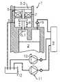
도 1은 선박 디젤 엔진(도시를 생략함)용 커먼-레일 장치의 형태의 본 발명의 일 구성에 따른 연료 분사 장치를 나타낸 것이다. 그러한 연료 분사 장치는 디 젤 연료가 주위 압력 하에 저장되어 있는 연료 저장 탱크 내지 연료 탱크(12)와, 연료 분사기들에 의해 선박 디젤 엔진의 연소실로 분사하기(도시를 생략함) 위해 연료가 고압 하에 저장되는 고압 저장 탱크(9)를 포함한다.1 shows a fuel injection device according to an embodiment of the present invention in the form of a common-rail device for a marine diesel engine (not shown). Such a fuel injecting apparatus includes a fuel storage tank or
연료를 연료 저장 탱크(12)로부터 고압 저장 탱크(9)로 급송하여 원하는 압력으로 하기 위해, 연료 저장 탱크와 고압 저장 탱크 사이에 3개의 고압 펌프들(1, 10, 11)이 병렬로 배치된다. 그러한 3개의 고압 펌프들은 구조적으로 거의 동일하므로, 이하에서는 도 1에 따로 상세하게 도시된 고압 펌프(1)에 대해서만 설명하기로 한다.Three high-
그러한 고압 펌프(1)는 흡입 라인(3)을 통해 연료 저장 탱크(12)에 연결된다. 비록 도시되어 있지는 않지만, 연료 저장 탱크(12)와 고압 저장 탱크(9) 사이에는 흡입 라인(3)에 일정한 공급 라인 압력을 형성하기 위해 급송 펌프 및/또는 승압 펌프들이 배치될 수도 있다.The high-pressure pump 1 is connected to the
고압 펌프(1)는 급송 측에서 급송 연결 라인(4)의 압력이 고압 저장 탱크(9)의 압력에 도달하거나 그를 넘어서는 즉시 고압 펌프가 연료를 고압 저장 탱크(9)로 밀어내도록 급송 연결 라인(4) 및 예컨대 스프링이 걸린 편향된 체크 밸브(6)를 통해 고압 저장 탱크(9)에 연결된다.The high pressure pump 1 is connected to the feed connection line (not shown) so that the high pressure pump immediately pushes the fuel to the high
흡입 연결 라인(3)과 예컨대 캠 윤곽(도시를 생략함)을 따라 왕복하는 피스톤(2)에 의해 주기적으로 확대 및 축소되는 고압 펌프(1)의 펌프실 사이에는, 능동 제어 가능한 흡입 밸브로서 자기 밸브(5)가 배치된다. 그러한 자기 밸브(5)는 도 1에 도시된 폐쇄 위치에서 펌프실을 연료 저장 탱크(12)에 대해 차단하는 밸브 캡(5.1)을 포함한다. 그러한 폐쇄 위치에서, 밸브 캡은 흡입 연결 라인(3)의 최대 공급 라인 압력과 펌프실 내의 최대 부압의 합보다 크거나 적어도 그와 같은 스프링력을 갖는 스프링(8)에 의해 편향된다.Between the
전자석(7)은 고압 펌프(1)의 하우징의 앵커실 내에 수납되는데, 앵커실은 보상 라인(compensating line)을 통해 흡입 연결 라인(3)에 유압 연결된다. 앵커실 내에는, 자기 밸브(5)의 앵커(5.2)가 전자석(7)의 여자 시에 끌어 당겨져 스프링(8)의 편향력을 극복하면서 자기 밸브를 개방하고, 그에 따라 피스톤(2)의 해당 이동(도 1의 아래쪽으로의)에 의한 펌프실 체적의 확대 시에 연료가 연료 저장 탱크(12)로부터 펌프실로 흐르게 하도록 수납된다. 전자석의 여자가 끊어졌을 때에는, 스프링이 자기 밸브(5)를 흡입 연결 라인(3)의 공급 라인 압력을 거슬러 다시 폐쇄 위치로 복귀시키고, 그에 따라 흡입 밸브가 압축 단계 동안 폐쇄되게 된다.The
피스톤(2)의 행정과 시간상으로 동기화되는 자기적으로 작동될 수 있는 흡입 밸브(5)는 작동 중에 피스톤(2)이 펌프실을 확대하는 흡입 단계 동안 한 번 이상 개방된다. 개방 단계들(개개의)의 길이에 의해 흡입량을 제어할 수 있다. 또한, 개방 위치와 폐쇄 위치의 시간 순번에 의해 압력 추이를 균등화하고, 특히 압력 변동을 줄일 수 있다. 예컨대, 우선 흡입 밸브(5)가 짧게 개방되어 펌프실 쪽으로 압력파를 생성한다. 중간 시간에 다시 폐쇄되는 흡입 밸브는 그러한 압력파가 연료 저장 탱크(12)에 되반사되는 것과 시간상으로 동기화되어 또 한 번 개방되고, 그에 따라 펌프실 쪽으로 또 다른 압력파가 유도된다. 그러한 압력파는 반대 방향의 반사 압력파와 간섭되어 펌프실이 균일하게 충전되게끔 한다. 물론, 흡입 밸브 는 예컨대 고압 펌프(1)의 흡입 단계 동안 거의 한 번만 개방될 수도 있다.The magnetically actuable suction valve 5 synchronized in time with the stroke of the
피스톤(2)이 펌프실을 축소하고, 편향력과 고압 저장 탱크(9)의 고압을 넘어설 때에 체크 밸브(6)를 통해 연료를 고압 하에 고압 저장 탱크(9)로 급송하는 압축 단계 동안에는 흡입 밸브(5)가 폐쇄된다. 피스톤의 행정을 그대로 유지하면서 급송량을 감소시키기 위해, 흡입 단계 동안 차단하는 것에 대해 부가적으로 또는 대안적으로 흡입 밸브(5)가 압축 단계 동안 한 번 이상 개방되어 연료를 연료 저장 탱크(12)로 되돌려 보낼 수도 있다.During the compression phase in which the
작업 사이클 동안 전자석(7)의 제어 작동을 변경함으로써, 특히 개방 시점 및/또는 폐쇄 시점을 변경함으로써, 변경된 부하 조건에 매우 신속하게 반응하여 그에 상응하게 급송량을 급변시킬 수 있다.By changing the control operation of the
흡입 연결 라인(3)에서의 연료의 원치 바람직하지 않은 역류 및 그곳에서 발생하는 공동화도 역시 전자석(7)의 적절한 제어 작동에 의해, 예컨대 흡입 밸브의 조기 폐쇄 및/또는 가벼운 폐쇄에 의해 감소시키거나 회피시킬 수 있다.The undesirable undesirable backwash of the fuel in the
연료 저장 탱크(12)와 흡입 연결 라인(3) 사이에 배치된 급송 펌프 또는 승압 펌프(도시를 생략함)가 고장이 나서(소위 블랙아웃) 흡입 연결 라인(3)의 공급 라인 압력이 떨어질 경우, 그렇다 하더라도 자기적으로 작동될 수 있는 흡입 밸브(5)의 능동 개방에 의해 펌프실을 충전하여 연료를 고압 하에 고압 저장 탱크(9)로 급송할 수 있게 된다.When the feed pump or the booster pump (not shown) disposed between the
구조상으로 거의 동일한 3개의 고압 펌프들(1, 10, 11)의 피스톤들은 해당 캠 윤곽들을 따라 동기적으로 또는 시간상으로 엇갈려 구동될 수 있다. 특히, 피 스톤들이 시간상으로 동기적으로 연료를 흡입 및 급송할 경우, 개개의 흡입 밸브를 개별적으로 제어 작동함으로써 압력 변동을 감소시킬 수 있다. 그를 위해, 여러 번의 개폐에 의해 압력 변동을 감소시킴과 더불어, 펌프들(1, 10, 11)의 개방 시점들 및/또는 폐쇄 시점들을 시간상으로 서로 엇갈리게 하여 모든 펌프들이 동일한 시점이 아니라 순차적으로 연료를 연료 저장 탱크(12)로부터 흡입하거나 그로 되돌려 보내도록 할 수 있다.The pistons of three substantially identical high pressure pumps 1, 10, 11 in structure can be driven synchronously or temporally staggered along their respective cam contours. In particular, when the pistons are inhaling and dispensing fuel synchronously in time, pressure fluctuations can be reduced by separately controlling and operating the individual intake valves. For this purpose, the opening times and / or closing times of the
하나의 펌프가 고장이 날 경우, 다른 펌프의 흡입 밸브를 적절히 제어 작동함으로써, 특히 흡입 단계 동안의 개방 시간을 연장함으로써 급송 손실을 적어도 부분적으로 보상할 수 있다.If one pump fails, the feed-in loss of at least partly can be compensated by appropriately controlling and operating the suction valve of the other pump, in particular by extending the opening time during the suction phase.
앵커실은 보상 라인을 통해 흡입 연결 라인(3)과 연통한다. 그럼으로써, 밸브 앵커(5.2)의 이동이 압력을 저지하지 않게 되어 흡입 밸브가 정해진 바의 힘으로 설계 및 작동될 수 있게 된다.The anchor chamber communicates with the suction connection line (3) through the compensation line. Thereby, the movement of the valve anchor (5.2) does not inhibit the pressure, so that the suction valve can be designed and operated with the specified bar force.
전자석(7) 및 스프링(7)을 부속한 자기 밸브(5)는 예컨대 밸브 지지체(valve support)에 배치될 수 있으나, 펌프 실린더에 배치될 수도 있고, 바람직한 구성에서는 클램핑 및 가이드 슬리브(도시를 생략함)와 액체 밀봉 나사 덮개에 의해 고정될 수 있다.The magnetic valve 5 to which the
도 1은 본 발명의 일 구성에 따른 연료 분사 장치를 나타낸 도면.BRIEF DESCRIPTION OF THE DRAWINGS Fig. 1 is a view showing a fuel injecting apparatus according to an embodiment of the present invention. Fig.
<도면의 주요 부분에 대한 부호의 설명>Description of the Related Art
1: 고압 펌프2: 피스톤1: High pressure pump 2: Piston
3: 흡입 연결 라인4: 급송 연결 라인3: Suction connection line 4: Feed connection line
5: 자기 밸브5.1: 밸브 캡5: magnetic valve 5.1: valve cap
5.2: 밸브 앵커6: 체크 밸브5.2: Valve anchor 6: Check valve
7: 전자석8: 편향 스프링7: Electromagnet 8: Deflection spring
9: 고압 저장 탱크10, 11: 고압 펌프9: High
12: 연료 저장 탱크12: Fuel storage tank
Claims (11)
Translated fromKoreanApplications Claiming Priority (2)
| Application Number | Priority Date | Filing Date | Title |
|---|---|---|---|
| DE102008050060.7 | 2008-10-01 | ||
| DE102008050060ADE102008050060A1 (en) | 2008-10-01 | 2008-10-01 | Common-rail fuel injection system for combustion engine, particularly marine diesel engine, has fuel reservoir and high pressure reservoir for filling of combustion chambers of combustion engine |
Publications (2)
| Publication Number | Publication Date |
|---|---|
| KR20100037559A KR20100037559A (en) | 2010-04-09 |
| KR101514464B1true KR101514464B1 (en) | 2015-04-22 |
Family
ID=41136374
Family Applications (1)
| Application Number | Title | Priority Date | Filing Date |
|---|---|---|---|
| KR1020090092934AActiveKR101514464B1 (en) | 2008-10-01 | 2009-09-30 | Fuel injection system having high-pressure pumps with magnetically operative suction valve |
Country Status (5)
| Country | Link |
|---|---|
| JP (1) | JP5528754B2 (en) |
| KR (1) | KR101514464B1 (en) |
| CN (1) | CN101713359B (en) |
| DE (1) | DE102008050060A1 (en) |
| FI (1) | FI20095906L (en) |
Families Citing this family (4)
| Publication number | Priority date | Publication date | Assignee | Title |
|---|---|---|---|---|
| DE102010031390B4 (en)* | 2010-07-15 | 2018-08-09 | Man Diesel & Turbo Se | Suction valve of a fuel supply system of an internal combustion engine |
| US20140034017A1 (en)* | 2011-04-27 | 2014-02-06 | Kazuhiro Omae | Adjustment device of high-pressure pump |
| JP6473045B2 (en)* | 2015-05-20 | 2019-02-20 | ヤマハ発動機株式会社 | Multi-cylinder engine and outboard motor |
| CN112483269B (en)* | 2020-12-16 | 2024-04-16 | 中车资阳机车有限公司 | Diesel engine safety protection system |
Citations (3)
| Publication number | Priority date | Publication date | Assignee | Title |
|---|---|---|---|---|
| JP2005282388A (en) | 2004-03-26 | 2005-10-13 | Denso Corp | Fuel supplying device for internal combustion engine |
| JP2008138566A (en)* | 2006-11-30 | 2008-06-19 | Mitsubishi Heavy Ind Ltd | Fuel injection device and operating method for engine |
| JP2008138567A (en) | 2006-11-30 | 2008-06-19 | Mitsubishi Heavy Ind Ltd | Fuel injection device and operating method for engine |
Family Cites Families (9)
| Publication number | Priority date | Publication date | Assignee | Title |
|---|---|---|---|---|
| US4757795A (en) | 1986-04-21 | 1988-07-19 | Stanadyne, Inc. | Method and apparatus for regulating fuel injection timing and quantity |
| US5058553A (en) | 1988-11-24 | 1991-10-22 | Nippondenso Co., Ltd. | Variable-discharge high pressure pump |
| US5133645A (en)* | 1990-07-16 | 1992-07-28 | Diesel Technology Corporation | Common rail fuel injection system |
| JP3446609B2 (en)* | 1998-06-01 | 2003-09-16 | トヨタ自動車株式会社 | Accumulator type fuel injection device |
| JP3110021B2 (en) | 1999-04-12 | 2000-11-20 | 株式会社ボッシュオートモーティブシステム | Fuel supply pump |
| DE10052629A1 (en) | 2000-10-24 | 2002-05-08 | Bosch Gmbh Robert | High pressure fuel pump with variable delivery rate |
| JP4478944B2 (en)* | 2004-12-17 | 2010-06-09 | 株式会社デンソー | Fluid metering valve and fuel injection pump using the same |
| JP4455470B2 (en)* | 2005-10-19 | 2010-04-21 | 日立オートモティブシステムズ株式会社 | Controller for high pressure fuel pump and normally closed solenoid valve of high pressure fuel pump |
| JP4535024B2 (en)* | 2006-04-27 | 2010-09-01 | 株式会社デンソー | Fuel pressure control device |
- 2008
- 2008-10-01DEDE102008050060Apatent/DE102008050060A1/ennot_activeCeased
- 2009
- 2009-09-03FIFI20095906Apatent/FI20095906L/ennot_activeApplication Discontinuation
- 2009-09-25JPJP2009221175Apatent/JP5528754B2/enactiveActive
- 2009-09-30KRKR1020090092934Apatent/KR101514464B1/enactiveActive
- 2009-09-30CNCN200910205203.3Apatent/CN101713359B/enactiveActive
Patent Citations (3)
| Publication number | Priority date | Publication date | Assignee | Title |
|---|---|---|---|---|
| JP2005282388A (en) | 2004-03-26 | 2005-10-13 | Denso Corp | Fuel supplying device for internal combustion engine |
| JP2008138566A (en)* | 2006-11-30 | 2008-06-19 | Mitsubishi Heavy Ind Ltd | Fuel injection device and operating method for engine |
| JP2008138567A (en) | 2006-11-30 | 2008-06-19 | Mitsubishi Heavy Ind Ltd | Fuel injection device and operating method for engine |
Also Published As
| Publication number | Publication date |
|---|---|
| FI20095906A0 (en) | 2009-09-03 |
| CN101713359A (en) | 2010-05-26 |
| FI20095906A7 (en) | 2010-04-02 |
| KR20100037559A (en) | 2010-04-09 |
| FI20095906L (en) | 2010-04-02 |
| JP5528754B2 (en) | 2014-06-25 |
| JP2010084761A (en) | 2010-04-15 |
| DE102008050060A1 (en) | 2010-04-08 |
| CN101713359B (en) | 2014-03-05 |
Similar Documents
| Publication | Publication Date | Title |
|---|---|---|
| KR100514275B1 (en) | High pressure pump | |
| JP5052656B2 (en) | High pressure fuel supply pump and fuel supply system | |
| CN101779033B (en) | Fuel pump | |
| US6619263B1 (en) | Fuel injection system for an internal combustion engine | |
| US6491017B1 (en) | Combined stroke/pressure controlled fuel injection method and system for an internal combustion engine | |
| US6520152B1 (en) | Fuel injection system for an internal combustion engine | |
| US20070144490A1 (en) | Control method of a common-rail type system for direct fuel injection into an internal combustion engine | |
| KR101087465B1 (en) | Fuel injectors for engines | |
| KR101514464B1 (en) | Fuel injection system having high-pressure pumps with magnetically operative suction valve | |
| US6499465B1 (en) | Fuel injection system for an internal combustion engine | |
| JP2003042040A (en) | Fuel injection device | |
| EP2241744A1 (en) | Common Rail Fuel Pump and Control Method for a Common Rail Fuel Pump | |
| JP3819208B2 (en) | Variable discharge fuel supply system | |
| US6725840B1 (en) | Fuel injection device | |
| JP4921886B2 (en) | Engine fuel supply system | |
| US10774820B2 (en) | Cryogenic pump | |
| US20070012293A1 (en) | Fuel injection system for internal combustion engines | |
| JP4404056B2 (en) | Fuel injection device for internal combustion engine | |
| JP2009103008A (en) | Fuel pump | |
| EP0992675A2 (en) | Fuel system | |
| WO2010082217A1 (en) | A fuel injection system for an internal combustion engine | |
| US20040099246A1 (en) | Fuel injector with multiple control valves | |
| JP4329761B2 (en) | Fuel injection device | |
| CN113785117A (en) | Fuel system with isolation valve between fuel injector and common drain conduit | |
| JP2007327424A (en) | Fuel supply device for internal combustion engine |
Legal Events
| Date | Code | Title | Description |
|---|---|---|---|
| PA0109 | Patent application | St.27 status event code:A-0-1-A10-A12-nap-PA0109 | |
| PG1501 | Laying open of application | St.27 status event code:A-1-1-Q10-Q12-nap-PG1501 | |
| PN2301 | Change of applicant | St.27 status event code:A-3-3-R10-R13-asn-PN2301 St.27 status event code:A-3-3-R10-R11-asn-PN2301 | |
| A201 | Request for examination | ||
| PA0201 | Request for examination | St.27 status event code:A-1-2-D10-D11-exm-PA0201 | |
| R17-X000 | Change to representative recorded | St.27 status event code:A-3-3-R10-R17-oth-X000 | |
| E902 | Notification of reason for refusal | ||
| PE0902 | Notice of grounds for rejection | St.27 status event code:A-1-2-D10-D21-exm-PE0902 | |
| T11-X000 | Administrative time limit extension requested | St.27 status event code:U-3-3-T10-T11-oth-X000 | |
| R17-X000 | Change to representative recorded | St.27 status event code:A-3-3-R10-R17-oth-X000 | |
| T11-X000 | Administrative time limit extension requested | St.27 status event code:U-3-3-T10-T11-oth-X000 | |
| E13-X000 | Pre-grant limitation requested | St.27 status event code:A-2-3-E10-E13-lim-X000 | |
| P11-X000 | Amendment of application requested | St.27 status event code:A-2-2-P10-P11-nap-X000 | |
| P13-X000 | Application amended | St.27 status event code:A-2-2-P10-P13-nap-X000 | |
| E701 | Decision to grant or registration of patent right | ||
| PE0701 | Decision of registration | St.27 status event code:A-1-2-D10-D22-exm-PE0701 | |
| GRNT | Written decision to grant | ||
| PR0701 | Registration of establishment | St.27 status event code:A-2-4-F10-F11-exm-PR0701 | |
| PR1002 | Payment of registration fee | St.27 status event code:A-2-2-U10-U11-oth-PR1002 Fee payment year number:1 | |
| PG1601 | Publication of registration | St.27 status event code:A-4-4-Q10-Q13-nap-PG1601 | |
| FPAY | Annual fee payment | Payment date:20180406 Year of fee payment:4 | |
| PR1001 | Payment of annual fee | St.27 status event code:A-4-4-U10-U11-oth-PR1001 Fee payment year number:4 | |
| PN2301 | Change of applicant | St.27 status event code:A-5-5-R10-R13-asn-PN2301 St.27 status event code:A-5-5-R10-R11-asn-PN2301 | |
| FPAY | Annual fee payment | Payment date:20190404 Year of fee payment:5 | |
| PR1001 | Payment of annual fee | St.27 status event code:A-4-4-U10-U11-oth-PR1001 Fee payment year number:5 | |
| PR1001 | Payment of annual fee | St.27 status event code:A-4-4-U10-U11-oth-PR1001 Fee payment year number:6 | |
| PR1001 | Payment of annual fee | St.27 status event code:A-4-4-U10-U11-oth-PR1001 Fee payment year number:7 | |
| PR1001 | Payment of annual fee | St.27 status event code:A-4-4-U10-U11-oth-PR1001 Fee payment year number:8 | |
| PR1001 | Payment of annual fee | St.27 status event code:A-4-4-U10-U11-oth-PR1001 Fee payment year number:9 | |
| PR1001 | Payment of annual fee | St.27 status event code:A-4-4-U10-U11-oth-PR1001 Fee payment year number:10 | |
| PN2301 | Change of applicant | St.27 status event code:A-5-5-R10-R13-asn-PN2301 St.27 status event code:A-5-5-R10-R11-asn-PN2301 |