KR101512233B1 - Multi shaft artificial foot with elastomer means - Google Patents
Multi shaft artificial foot with elastomer meansDownload PDFInfo
- Publication number
- KR101512233B1 KR101512233B1KR1020130093486AKR20130093486AKR101512233B1KR 101512233 B1KR101512233 B1KR 101512233B1KR 1020130093486 AKR1020130093486 AKR 1020130093486AKR 20130093486 AKR20130093486 AKR 20130093486AKR 101512233 B1KR101512233 B1KR 101512233B1
- Authority
- KR
- South Korea
- Prior art keywords
- ankle
- band
- adapter
- connection
- elastic material
- Prior art date
- Legal status (The legal status is an assumption and is not a legal conclusion. Google has not performed a legal analysis and makes no representation as to the accuracy of the status listed.)
- Expired - Fee Related
Links
Images


Classifications
- A—HUMAN NECESSITIES
- A61—MEDICAL OR VETERINARY SCIENCE; HYGIENE
- A61F—FILTERS IMPLANTABLE INTO BLOOD VESSELS; PROSTHESES; DEVICES PROVIDING PATENCY TO, OR PREVENTING COLLAPSING OF, TUBULAR STRUCTURES OF THE BODY, e.g. STENTS; ORTHOPAEDIC, NURSING OR CONTRACEPTIVE DEVICES; FOMENTATION; TREATMENT OR PROTECTION OF EYES OR EARS; BANDAGES, DRESSINGS OR ABSORBENT PADS; FIRST-AID KITS
- A61F2/00—Filters implantable into blood vessels; Prostheses, i.e. artificial substitutes or replacements for parts of the body; Appliances for connecting them with the body; Devices providing patency to, or preventing collapsing of, tubular structures of the body, e.g. stents
- A61F2/50—Prostheses not implantable in the body
- A61F2/60—Artificial legs or feet or parts thereof
- A61F2/66—Feet; Ankle joints
- A61F2/6607—Ankle joints
- A—HUMAN NECESSITIES
- A61—MEDICAL OR VETERINARY SCIENCE; HYGIENE
- A61F—FILTERS IMPLANTABLE INTO BLOOD VESSELS; PROSTHESES; DEVICES PROVIDING PATENCY TO, OR PREVENTING COLLAPSING OF, TUBULAR STRUCTURES OF THE BODY, e.g. STENTS; ORTHOPAEDIC, NURSING OR CONTRACEPTIVE DEVICES; FOMENTATION; TREATMENT OR PROTECTION OF EYES OR EARS; BANDAGES, DRESSINGS OR ABSORBENT PADS; FIRST-AID KITS
- A61F2/00—Filters implantable into blood vessels; Prostheses, i.e. artificial substitutes or replacements for parts of the body; Appliances for connecting them with the body; Devices providing patency to, or preventing collapsing of, tubular structures of the body, e.g. stents
- A61F2/50—Prostheses not implantable in the body
- A61F2/60—Artificial legs or feet or parts thereof
- A61F2/66—Feet; Ankle joints
- A61F2002/6614—Feet
- A61F2002/6642—Heels
- A—HUMAN NECESSITIES
- A61—MEDICAL OR VETERINARY SCIENCE; HYGIENE
- A61F—FILTERS IMPLANTABLE INTO BLOOD VESSELS; PROSTHESES; DEVICES PROVIDING PATENCY TO, OR PREVENTING COLLAPSING OF, TUBULAR STRUCTURES OF THE BODY, e.g. STENTS; ORTHOPAEDIC, NURSING OR CONTRACEPTIVE DEVICES; FOMENTATION; TREATMENT OR PROTECTION OF EYES OR EARS; BANDAGES, DRESSINGS OR ABSORBENT PADS; FIRST-AID KITS
- A61F2/00—Filters implantable into blood vessels; Prostheses, i.e. artificial substitutes or replacements for parts of the body; Appliances for connecting them with the body; Devices providing patency to, or preventing collapsing of, tubular structures of the body, e.g. stents
- A61F2/50—Prostheses not implantable in the body
- A61F2/60—Artificial legs or feet or parts thereof
- A61F2/66—Feet; Ankle joints
- A61F2002/6614—Feet
- A61F2002/6657—Feet having a plate-like or strip-like spring element, e.g. an energy-storing cantilever spring keel
Landscapes
- Health & Medical Sciences (AREA)
- Transplantation (AREA)
- Biomedical Technology (AREA)
- Cardiology (AREA)
- Oral & Maxillofacial Surgery (AREA)
- Engineering & Computer Science (AREA)
- Orthopedic Medicine & Surgery (AREA)
- Heart & Thoracic Surgery (AREA)
- Vascular Medicine (AREA)
- Life Sciences & Earth Sciences (AREA)
- Animal Behavior & Ethology (AREA)
- General Health & Medical Sciences (AREA)
- Public Health (AREA)
- Veterinary Medicine (AREA)
- Prostheses (AREA)
Abstract
Translated fromKoreanDescription
Translated fromKorean본 발명은 탄성재가 주입된 다축인공발에 관한 것이다.The present invention relates to a multi-axis artificial foot into which an elastic material is injected.
인공발은 바닥에 닿는 부분과 관절을 연결하는 어댑터 부분으로 이루어진다(국내공개특허10-2010-0052920호, 공개특허10-2006-0072123호). 그러나 이러한 구조는 충격을 흡수하는 수단이 상하로의 충격을 흡수하는 것이어서 좌우로의 충격흡수가 미흡하여 인간의 발의 특성을 그대로 구현하기 어려운 현실이다.
The artificial foot is composed of a portion contacting the floor and an adapter portion connecting the joints (Korean Patent Laid-Open No. 10-2010-0052920, Laid-open Patent No. 10-2006-0072123). However, in such a structure, the means for absorbing the shock absorbs the impact of the up and down directions, so that the shock absorption to the right and left is insufficient and it is difficult to realize the characteristics of the human foot as it is.
본 발명은 이를 해결하고자 하는 것으로, 본 발명의 목적은 바닥 킬재를 지지하는 킬재연결어댑터와, 발목과 연결하는 피라밋 연결소켓을 가지는 발목연결어댑터와, 상하의 이들 어댑터 사이에 안치되는 탄성재와, 탄성재 내에서 상하의 어댑터를 지지하는 밴드를 부가하여 탄성재에서는 상하로의 쿠션을 주고, 밴드는 좌우로의 과도한 뒤틀림을 제한하여 상하 좌우의 움직임이 가능하도록 하여 인간 본연의 발의 기능을 근접하게 구현 가능토록 하는 탄성재가 주입된 다축인공발을 제공하려는 것이다.It is an object of the present invention to solve the problems described above, and it is an object of the present invention to provide an ankle coupling adapter having a cheek connecting adapter for supporting a floor keel, an ankle connecting adapter having a pyramid connecting socket for connecting the ankle, By adding bands that support the upper and lower adapters in the material, the elastic material can give upper and lower cushions, and the band can restrict excessive twisting to the left and right, making it possible to move up and down and left and right. A multi-axis artificial foot into which an elastic material is inserted.
본 발명의 다른 목적은 바닥 킬재를 지지하는 킬재연결어댑터와, 발목과 연결하는 피라밋 연결소켓을 가지는 발목연결어댑터와, 상하의 이들 어댑터 사이에 안치되는 탄성재와, 탄성재 내에서 상하의 어댑터를 지지하는 밴드를 부가하고 탄성재의 뒷부분과 킬재사이는 경사진 경사면을 두어 뒷굽으로의 충격력 전달시 발굽에 가해지는 충격력을 흡수토록 하는 탄성재가 주입된 다축인공발을 제공하려는 것이다.Another object of the present invention is to provide an ankle connecting adapter having a cheek connecting adapter for supporting a floor keel, an ankle connecting adapter having a pyramid connecting socket for connecting to the ankle, an elastic material positioned between the upper and lower adapters, And to provide a multiaxial artificial foot having an inclined surface between the rear portion of the elastic material and the inclined surface to absorb the impact force applied to the hoof when the impact force is transmitted to the backhoe.
본 발명의 다른 목적은 바닥 킬재를 지지하는 킬재연결어댑터와, 발목과 연결하는 피라밋 연결소켓을 가지는 발목연결어댑터와, 상하의 이들 어댑터 사이에 안치되는 탄성재와, 탄성재 내에서 상하의 어댑터를 지지하는 밴드로 구성하고, 밴드는 킬재의 폭방향중앙에 길이방향으로 전후방에 위치하도록 하여 탄성재가 발목연결어댑터와 킬재를 탄성력있게 결합하고 뒤틀림이 있어도 전후방에서 킬재의 폭방향중앙에 길이방향으로 밴드가 지지하여주므로 발이 꺽임 없이 지지되도록 하는 탄성재가 주입된 다축인공발을 제공하려는 것이다.Another object of the present invention is to provide an ankle connecting adapter having a cheek connecting adapter for supporting a floor keel, an ankle connecting adapter having a pyramid connecting socket for connecting to the ankle, an elastic material positioned between the upper and lower adapters, Band, and the band is positioned longitudinally in the longitudinal direction at the center in the width direction of the keel so that the elastic material elastically couples the ankle connecting adapter and the keel material and the band is supported in the longitudinal direction at the center in the width direction of the keel, So that the foot is supported without bending.
이를 위하여 본원발명은 하퇴, 대퇴 절단자가 의족과 연결하는 다축 작동방식의 인공발용 발목연결 어댑터;For this purpose, the present invention relates to a multi-axis operated artificial foot ankle connection adapter connecting the lower leg and the femoral cutter to the prosthesis;
킬재(keel)를 연결하는 킬재연결 어댑터; 및A keel connection adapter connecting the keel; And
인공발용 발목연결 어댑터와 킬재연결 어댑터사이에 주입하여 족관절 운동기능을 하도록 한 탄성재를 포함하여 구성하고;And an elastic member for performing an ankle joint function by being injected between an artificial foot ankle connecting adapter and a keel connecting adapter;
상기 발목연결 어댑터와 킬재연결 어댑터 사이에서 탄성재를 상하로 전방과 후방에 2개의 밴드로 구속하여 탄성재의 이탈 및 과신전을 방지하고 보행시 탄성재가 전방-후방 쿠션기능 및 좌우 회전, 비틀림 기능을 하도록 한 탄성재가 주입된 다축인공발을 제공한다.The elastic material between the ankle connecting adapter and the kelly connecting adapter is restrained by the upper and lower bands in the front and the back two bands to prevent the elastic material from escaping and overcoming the elasticity, and the elastic material acts as a front- And provides an elastomeric multi-axis artificial foot with injection.
본 발명은 바닥 킬재를 지지하는 킬재연결어댑터와, 발목과 연결하는 피라밋 연결소켓을 가지는 발목연결어댑터와, 상하의 이들 어댑터 사이에 안치되는 탄성재와, 탄성재 내에서 상하의 어댑터를 지지하는 밴드를 부가하여 탄성재에서는 상하로의 쿠션을 주고, 밴드는 좌우로의 과도한 뒤틀림을 제한하여 상하 좌우의 움직임이 가능하도록 하여 인간 본연의 발의 기능을 근접하게 구현 가능토록 한다.The present invention relates to an elastic member which is placed between upper and lower adapters, an ankle connection adapter having a pyramid connection socket to be connected to an ankle, Thus, the cushion of the elastic material is given to the upper and lower portions, and the band is allowed to move in the up and down directions by restricting the excessive warping to the left and right.
본 발명은 바닥 킬재를 지지하는 킬재연결어댑터와, 발목과 연결하는 피라밋 연결소켓을 가지는 발목연결어댑터와, 상하의 이들 어댑터 사이에 안치되는 탄성재와, 탄성재 내에서 상하의 어댑터를 지지하는 밴드를 부가하고 탄성재의 뒷부분과 킬재사이는 경사진 경사면을 두어 뒷굽으로의 충격력 전달시 발굽에 가해지는 충격력을 흡수토록 한다.The present invention relates to an elastic member which is placed between upper and lower adapters, an ankle connection adapter having a pyramid connection socket to be connected to an ankle, And a sloping inclined surface between the rear part of the elastic material and the keel material is provided to absorb the impact force applied to the hoof when the impact force is transmitted to the hoof.
본 발명은 바닥 킬재를 지지하는 킬재연결어댑터와, 발목과 연결하는 피라밋 연결소켓을 가지는 발목연결어댑터와, 상하의 이들 어댑터 사이에 안치되는 탄성재와, 탄성재 내에서 상하의 어댑터를 지지하는 밴드로 구성하고, 밴드는 킬재의 폭방향중앙에 길이방향으로 전후방에 위치하도록 하여 탄성재가 발목연결어댑터와 킬재를 탄성력있게 결합하고 뒤틀림이 있어도 전후방에서 킬재의 폭방향중앙에 길이방향으로 밴드가 지지하여주므로 발이 꺽임 없이 지지되도록 한다.The present invention relates to a golf club head comprising: a keel connecting adapter for supporting a floor keel; an ankle connecting adapter having a pyramid connecting socket connected to the ankle; an elastic material positioned between the upper and lower adapters; and a band for supporting the upper and lower adapters in the elastic material And the band is located at the center in the width direction of the keel in the longitudinal direction so that the elastic material elastically connects the ankle connecting adapter and the keel material and the band is supported in the longitudinal direction at the center in the width direction of the keel, Be supported without bending.
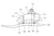
도 1은 본 발명의 사시도,
도 2는 본발명의 단면도,
도 3은 본 발명의 사용상태를 보인 측면도,
도 4는 본 발명의 사용상태를 보인 평면도,
도 5는 본발명의 사용상태를 보인 정면도이다.1 is a perspective view of the present invention,
2 is a cross-sectional view of the present invention,
3 is a side view showing the use state of the present invention,
4 is a plan view showing the use state of the present invention,
5 is a front view showing the use state of the present invention.
이하 본원발명의 실시예를 도면을 참조하여 상세히 설명한다.Hereinafter, embodiments of the present invention will be described in detail with reference to the drawings.
본 발명은 하퇴, 대퇴 절단자가 의족과 연결하는 다축 작동방식의 인공발용 발목연결 어댑터(10);The present invention relates to a multifactor ankle
킬재(keel)를 연결하는 킬재연결 어댑터(20); 및A keel connection adapter 20 connecting the keel; And
인공발용 발목연결 어댑터(10)와 킬재연결 어댑터(20)사이에 주입하여 족관절 운동기능을 하도록 한 탄성재(30)를 포함하여 구성하고;And an elastic material (30) injected between the artificial foot ankle connection adapter (10) and the kelly connection adapter (20) to perform an ankle joint motion function;
상기 발목연결 어댑터(10)와 킬재연결 어댑터(20) 사이에서 탄성재(30)를 상하로 전방과 후방에 2개의 밴드로 구속하여 탄성재(30)의 이탈 및 과신전을 방지하고 보행시 탄성재(30)가 전방-후방 쿠션기능 및 좌우 회전, 비틀림 기능을 하도록 구성한다.The
상기, 발목연결 어댑터(10)는 발목연결용 피라밋형연결소켓(11)과, 2개의 상부 밴드연결핀(13,14)을 가지고 있으며 저면이 탄성재를 주입하기 위한 캐비티(15) 형태이고, 킬재연결 어댑터(20)는 하부 밴드연결핀(23,24)을 가지면서 발바닥 역할을 하는 킬재(22)를 결합하고,The
상기 캐비티(15)에 체중심을 기준으로 전방과 후방에 상기 상부 밴드연결핀(13,14)와 하부 밴드연결핀(23,24)를 전방부와 후방부에서 전방밴드(16)와 후방밴드(17)로 각각 연결하고, 캐비티(15)와 킬재연결어댑터(20) 사이에 탄성재를 주입하여 전방밴드(16)와 후방밴드(17)를 둘러싸도록 하여 쿠션 및 과변형을 방지하도록 구성한다.The upper
상기, 발목연결 어댑터(10)의 저면에 캐비티(15)를 이루는 측벽은 전방이 후방보다 킬재(22)에 근접하도록 구성하고, 후방의 탄성재(30) 저면은 발목의 전후 운동을 가능토록 경사면(31)을 이룬다.The side wall constituting the
상기, 탄성재(30)의 전방 저면은 킬재(22)와 전방운동 가능토록 전방측 캐비티(15)를 이루는 측벽보다 길게 노출면(32)이 노출되도록 구성한다.The front bottom surface of the
상기, 상기 상부 밴드연결핀(13,14)와 하부 밴드연결핀(23,24)를 전방부와 후방부에서 상하로 각각 연결하는 전방밴드(16)와 후방밴드(17)는 킬재(22)의 폭방향 중앙에 길이방향과 일치하도록 구성한다.The
이와같은 구성을 이룬 본 발명은 통상의 바닥판인 킬재(22)의 상면 중앙에 볼트나 본드 같은 결합수단을 사용하여 킬재연결어댑터(20)를 결합한다. 킬재연결어댑터(20) 상면에는 밴드(16,17)를 각각 고정시키는 밴드연결핀(23,24)를 부가한다. 또한 저면에는 하부가 개방된 캐비티(15)를 이루고 캐비티(15) 바닥면에는 상기 밴드연결핀(23,24)과 수직으로 이격된 위치에 밴드연결핀(13,14)을 추가로 부가한다음, 상호 전방밴드(16)와 후방밴드(17)를 이루도록 연결하되, 상호 일정 이격거리를 가지도록 도시하지않은 지그를 사용하여 거리를 유지한 상태에서 우레탄 같은 발포재를 부어서 성형하면 도 2 단면도와 같은 상태로 성형이 이루어진다. 물론 이 경우 뒷굽의 탄성재(30)에는 외측으로 갈수록 상향 경사진 경사면(31)을 이루고, 전방의 저면에는 노출면(32)으로 캐비티(15)의 측벽보다 노출되도록 하여 탄성력이 킬재(22) 바닥면에 작용하도록 한다.According to the present invention having such a structure, a
이와같이 성형한 본원발명은 킬재(22)와 발목연결 어댑터(10)를 인공스킨으로 감싸도록 하여 사용하며, 이러한 인공스킨의 도시는 통상적인 기술이므로 생략한다. 아울러 헤드고정볼트(12)로 피라밋 연결소켓(11)과 발목연결 어댑터(10)를 결합한 상태이므로 피라밋연결소켓(11)에 인공발목(도시하지 않음)을 결합하여 사용한다.In the present invention thus formed, the
사용시 전후방으로는 캐비티(15) 외부로 도 3 과 같이 전방에는 노출면(32)이 후방에는 경사진 경사면(31)을 이루도록 노출되므로, 무게중심축인 헤드고정볼트(12)를 중심으로 전후방으로의 충격력을 발생시키도록 작용하고, 이는 자연스런 보행을 가능토록 한다.The exposed
아울러 도 4 및 도 5 와 같이 헤드고정볼트(12)를 중심으로 시계방향 또는 반시계 반향으로 뒤틀리는 힘이 작용하여도 복원력에 의하여 항상 정위치로 복원하므로 정상적인 보행을 지속적으로 하게된다. 이는 상부의 밴드연결핀(13,14)과 이에 대응하는 하부의 밴드연결핀(23,24)을 전방밴드(16) 및 후방밴드(17)로 킬재(220의 폭방향 중앙에서 길이방향으로 지지하므로, 기존의 탄성재(30)에 의한 탄성력에 뒤틀림이 발생하여도 전방밴드(16) 및 후방밴드(17)가 원위치하는 복원력을 제공하기 때문이다.As shown in FIGS. 4 and 5, when the
10;발목연결 어댑터 11;피라밋연결 소켓 12;헤드고정볼트 13,14;밴드연결핀 15;캐비티 16;전방밴드 17;후방밴드 20;킬재연결 어댑터 22;킬재 23,24;밴드연결핀 30;탄성재 31;경사면 32;노출면An ankle connecting adapter (11), a pyramid connecting socket (12), a head fixing bolt (13,14), a band connecting pin (15), a cavity (16), a front band (17), a rear band (20)
Claims (5)
Translated fromKorean킬재(keel)를 연결하는 킬재연결 어댑터(20); 및
인공발용 발목연결 어댑터(10)와 킬재연결 어댑터(20)사이에 주입하여 족관절 운동기능을 하도록 한 탄성재(30)를 포함하여 구성하고;
상기 발목연결 어댑터(10)와 킬재연결 어댑터(20) 사이에서 탄성재(30)를 상하로 전방과 후방에 2개의 밴드로 구속하여 탄성재(30)의 이탈 및 과신전을 방지하고 보행시 탄성재(30)가 전방-후방 쿠션기능 및 좌우 회전, 비틀림 기능을 하도록 하며;
상기, 발목연결 어댑터(10)는 발목연결용 피라밋형연결소켓(11)과, 2개의 상부 밴드연결핀(13,14)을 가지고 있으며 저면이 탄성재를 주입하기 위한 캐비티(15) 형태이고, 킬재연결 어댑터(20)는 하부 밴드연결핀(23,24)을 가지면서 발바닥 역할을 하는 킬재(22)를 결합하고,
상기 캐비티(15)에 체중심을 기준으로 전방과 후방에 상기 상부 밴드연결핀(13,14)와 하부 밴드연결핀(23,24)를 전방부와 후방부에서 전방밴드(16)와 후방밴드(17)로 각각 연결하고, 캐비티(15)와 킬재연결어댑터(20) 사이에 탄성재를 주입하여 전방밴드(16)와 후방밴드(17)를 둘러싸도록 하여 쿠션 및 과변형을 방지하도록 하는 탄성재가 주입된 다축인공발.
A multi-axis working ankle ankle connection adapter (10) connecting the lower legs to the femoral cutter's prosthesis;
A keel connection adapter 20 connecting the keel; And
And an elastic material (30) injected between the artificial foot ankle connection adapter (10) and the kelly connection adapter (20) to perform an ankle joint motion function;
The elastic material 30 is restrained between the ankle connecting adapter 10 and the kelly connecting adapter 20 by two bands in the front and rear directions in the up and down directions to prevent the elastic material 30 from escaping and overcoming, (30) functions as a front-rear cushion function and a left-right rotation, twist function;
The ankle connecting adapter 10 has a pyramidal connection socket 11 for ankle connection and two upper band connection pins 13 and 14 and a bottom surface is in the form of a cavity 15 for injecting an elastic material, The center connection adapter 20 has the lower band connection pins 23 and 24 and joins the sole 22 serving as the sole,
The upper band connecting pins 13 and 14 and the lower band connecting pins 23 and 24 are provided on the front and rear sides of the front and rear bands 16 and 17 in the front and rear sides of the cavity 15, 17 and an elastic material is injected between the cavity 15 and the connecting member 20 to surround the front band 16 and the rear band 17 to prevent cushion and deformation Multi-axis artificial foot injected.
The ankle connecting adapter according to claim 2, wherein the side wall forming the cavity (15) on the bottom surface of the ankle connecting adapter (10) is configured such that the front side is closer to the keel material (22) than the rear side, Wherein the inclined surface (31) is formed so as to allow the elastic member (30) to be inserted.
The elastic material (30) according to claim 3, wherein the front bottom surface of the elastic material (30) is configured to expose the exposed surface (32) longer than a sidewall of the front cavity (15) Multi-axis artificial foot injected.
The front band (16) and the rear band (17) for connecting the upper band connection pin (13,14) and the lower band connection pin (23,24) vertically at the front portion and the rear portion, respectively, Wherein the elastic member is provided so as to coincide with the longitudinal direction at the center in the width direction of the kiln material (22).
Priority Applications (1)
| Application Number | Priority Date | Filing Date | Title |
|---|---|---|---|
| KR1020130093486AKR101512233B1 (en) | 2013-08-07 | 2013-08-07 | Multi shaft artificial foot with elastomer means |
Applications Claiming Priority (1)
| Application Number | Priority Date | Filing Date | Title |
|---|---|---|---|
| KR1020130093486AKR101512233B1 (en) | 2013-08-07 | 2013-08-07 | Multi shaft artificial foot with elastomer means |
Publications (2)
| Publication Number | Publication Date |
|---|---|
| KR20150017504A KR20150017504A (en) | 2015-02-17 |
| KR101512233B1true KR101512233B1 (en) | 2015-04-16 |
Family
ID=53046328
Family Applications (1)
| Application Number | Title | Priority Date | Filing Date |
|---|---|---|---|
| KR1020130093486AExpired - Fee RelatedKR101512233B1 (en) | 2013-08-07 | 2013-08-07 | Multi shaft artificial foot with elastomer means |
Country Status (1)
| Country | Link |
|---|---|
| KR (1) | KR101512233B1 (en) |
Cited By (1)
| Publication number | Priority date | Publication date | Assignee | Title |
|---|---|---|---|---|
| RU208436U1 (en)* | 2021-06-28 | 2021-12-17 | Общество с ограниченной ответственностью "Группа компаний "САЛЮТ ОРТО" | Knee prosthesis |
Citations (2)
| Publication number | Priority date | Publication date | Assignee | Title |
|---|---|---|---|---|
| KR100401457B1 (en) | 2000-11-27 | 2003-10-10 | 산재의료관리원 | Multi-functioning artificial foot |
| JP4369125B2 (en) | 2001-03-30 | 2009-11-18 | ダブリュ タウンゼンド、バリー | Prosthetic leg with adjustable performance |
- 2013
- 2013-08-07KRKR1020130093486Apatent/KR101512233B1/ennot_activeExpired - Fee Related
Patent Citations (2)
| Publication number | Priority date | Publication date | Assignee | Title |
|---|---|---|---|---|
| KR100401457B1 (en) | 2000-11-27 | 2003-10-10 | 산재의료관리원 | Multi-functioning artificial foot |
| JP4369125B2 (en) | 2001-03-30 | 2009-11-18 | ダブリュ タウンゼンド、バリー | Prosthetic leg with adjustable performance |
Cited By (1)
| Publication number | Priority date | Publication date | Assignee | Title |
|---|---|---|---|---|
| RU208436U1 (en)* | 2021-06-28 | 2021-12-17 | Общество с ограниченной ответственностью "Группа компаний "САЛЮТ ОРТО" | Knee prosthesis |
Also Published As
| Publication number | Publication date |
|---|---|
| KR20150017504A (en) | 2015-02-17 |
Similar Documents
| Publication | Publication Date | Title |
|---|---|---|
| US10881533B2 (en) | Prosthetic foot including a heel cap and interchangeable heel-side spring-damper | |
| US12035777B2 (en) | Shoe sole and a shoe comprising such sole | |
| TWI423791B (en) | Kuenstlicher fuss und verfahren zur steuerung der bewegung eines kuenstlichen fusses | |
| US20070271818A1 (en) | Shoe spring and shock absorbing system | |
| BRPI1103840A2 (en) | foot prosthesis | |
| CN103720129B (en) | Shoe sole | |
| US20190125552A1 (en) | Prosthetic foot with spaced spring elements | |
| KR101512233B1 (en) | Multi shaft artificial foot with elastomer means | |
| CN105476176A (en) | Shock absorbing sole | |
| US20120209406A1 (en) | Foot Plate Device for An Artificial Foot | |
| US20250127634A1 (en) | Prosthetic foot with spaced spring elements | |
| CN207519708U (en) | With the sole shock structure for stablizing support | |
| KR20110112975A (en) | Shoe soles | |
| CN102309089B (en) | Shoe sole with flexibility and torsional stability | |
| KR20110001665U (en) | Assistant for heel of a shoes | |
| KR20080102835A (en) | Spring-replaceable shoes | |
| KR200455079Y1 (en) | Shoes with midsole with straight walking induction | |
| CN105962531A (en) | Shock-relieving and powered bubble massage sports shoe | |
| KR20100011831U (en) | Assistance shoes heel | |
| KR20070077300A (en) | Functional shoe insoles | |
| CN102266148B (en) | Sole with elastic structure | |
| KR101251586B1 (en) | a sole having shock absorbing and distributing function | |
| CN105901833A (en) | Breathable and comfortable bubbly cushioned shoe sole | |
| CN105394878A (en) | Rebound power assisting device for shoe sole | |
| CN201995723U (en) | Buffering and damping soles |
Legal Events
| Date | Code | Title | Description |
|---|---|---|---|
| A201 | Request for examination | ||
| PA0109 | Patent application | St.27 status event code:A-0-1-A10-A12-nap-PA0109 | |
| PA0201 | Request for examination | St.27 status event code:A-1-2-D10-D11-exm-PA0201 | |
| D13-X000 | Search requested | St.27 status event code:A-1-2-D10-D13-srh-X000 | |
| D14-X000 | Search report completed | St.27 status event code:A-1-2-D10-D14-srh-X000 | |
| E902 | Notification of reason for refusal | ||
| PE0902 | Notice of grounds for rejection | St.27 status event code:A-1-2-D10-D21-exm-PE0902 | |
| E13-X000 | Pre-grant limitation requested | St.27 status event code:A-2-3-E10-E13-lim-X000 | |
| P11-X000 | Amendment of application requested | St.27 status event code:A-2-2-P10-P11-nap-X000 | |
| P13-X000 | Application amended | St.27 status event code:A-2-2-P10-P13-nap-X000 | |
| PG1501 | Laying open of application | St.27 status event code:A-1-1-Q10-Q12-nap-PG1501 | |
| E701 | Decision to grant or registration of patent right | ||
| PE0701 | Decision of registration | St.27 status event code:A-1-2-D10-D22-exm-PE0701 | |
| PR0701 | Registration of establishment | St.27 status event code:A-2-4-F10-F11-exm-PR0701 | |
| PR1002 | Payment of registration fee | St.27 status event code:A-2-2-U10-U11-oth-PR1002 Fee payment year number:1 | |
| PG1601 | Publication of registration | St.27 status event code:A-4-4-Q10-Q13-nap-PG1601 | |
| P22-X000 | Classification modified | St.27 status event code:A-4-4-P10-P22-nap-X000 | |
| R18-X000 | Changes to party contact information recorded | St.27 status event code:A-5-5-R10-R18-oth-X000 | |
| P22-X000 | Classification modified | St.27 status event code:A-4-4-P10-P22-nap-X000 | |
| FPAY | Annual fee payment | Payment date:20180403 Year of fee payment:4 | |
| PR1001 | Payment of annual fee | St.27 status event code:A-4-4-U10-U11-oth-PR1001 Fee payment year number:4 | |
| FPAY | Annual fee payment | Payment date:20190403 Year of fee payment:5 | |
| PR1001 | Payment of annual fee | St.27 status event code:A-4-4-U10-U11-oth-PR1001 Fee payment year number:5 | |
| PR1001 | Payment of annual fee | St.27 status event code:A-4-4-U10-U11-oth-PR1001 Fee payment year number:6 | |
| PR1001 | Payment of annual fee | St.27 status event code:A-4-4-U10-U11-oth-PR1001 Fee payment year number:7 | |
| PR1001 | Payment of annual fee | St.27 status event code:A-4-4-U10-U11-oth-PR1001 Fee payment year number:8 | |
| PR1001 | Payment of annual fee | St.27 status event code:A-4-4-U10-U11-oth-PR1001 Fee payment year number:9 | |
| PC1903 | Unpaid annual fee | St.27 status event code:A-4-4-U10-U13-oth-PC1903 Not in force date:20240409 Payment event data comment text:Termination Category : DEFAULT_OF_REGISTRATION_FEE | |
| PC1903 | Unpaid annual fee | St.27 status event code:N-4-6-H10-H13-oth-PC1903 Ip right cessation event data comment text:Termination Category : DEFAULT_OF_REGISTRATION_FEE Not in force date:20240409 |