KR101507206B1 - Flexible Display Device - Google Patents
Flexible Display DeviceDownload PDFInfo
- Publication number
- KR101507206B1 KR101507206B1KR1020120014436AKR20120014436AKR101507206B1KR 101507206 B1KR101507206 B1KR 101507206B1KR 1020120014436 AKR1020120014436 AKR 1020120014436AKR 20120014436 AKR20120014436 AKR 20120014436AKR 101507206 B1KR101507206 B1KR 101507206B1
- Authority
- KR
- South Korea
- Prior art keywords
- display panel
- flexible display
- curved surface
- external circuit
- signal
- Prior art date
- Legal status (The legal status is an assumption and is not a legal conclusion. Google has not performed a legal analysis and makes no representation as to the accuracy of the status listed.)
- Active
Links
Images


Classifications
- G—PHYSICS
- G09—EDUCATION; CRYPTOGRAPHY; DISPLAY; ADVERTISING; SEALS
- G09F—DISPLAYING; ADVERTISING; SIGNS; LABELS OR NAME-PLATES; SEALS
- G09F9/00—Indicating arrangements for variable information in which the information is built-up on a support by selection or combination of individual elements
- G09F9/30—Indicating arrangements for variable information in which the information is built-up on a support by selection or combination of individual elements in which the desired character or characters are formed by combining individual elements
- G09F9/301—Indicating arrangements for variable information in which the information is built-up on a support by selection or combination of individual elements in which the desired character or characters are formed by combining individual elements flexible foldable or roll-able electronic displays, e.g. thin LCD, OLED
- G—PHYSICS
- G09—EDUCATION; CRYPTOGRAPHY; DISPLAY; ADVERTISING; SEALS
- G09G—ARRANGEMENTS OR CIRCUITS FOR CONTROL OF INDICATING DEVICES USING STATIC MEANS TO PRESENT VARIABLE INFORMATION
- G09G3/00—Control arrangements or circuits, of interest only in connection with visual indicators other than cathode-ray tubes
- G09G3/03—Control arrangements or circuits, of interest only in connection with visual indicators other than cathode-ray tubes specially adapted for displays having non-planar surfaces, e.g. curved displays
- G09G3/035—Control arrangements or circuits, of interest only in connection with visual indicators other than cathode-ray tubes specially adapted for displays having non-planar surfaces, e.g. curved displays for flexible display surfaces
- G—PHYSICS
- G09—EDUCATION; CRYPTOGRAPHY; DISPLAY; ADVERTISING; SEALS
- G09G—ARRANGEMENTS OR CIRCUITS FOR CONTROL OF INDICATING DEVICES USING STATIC MEANS TO PRESENT VARIABLE INFORMATION
- G09G3/00—Control arrangements or circuits, of interest only in connection with visual indicators other than cathode-ray tubes
- G09G3/20—Control arrangements or circuits, of interest only in connection with visual indicators other than cathode-ray tubes for presentation of an assembly of a number of characters, e.g. a page, by composing the assembly by combination of individual elements arranged in a matrix no fixed position being assigned to or needed to be assigned to the individual characters or partial characters
- G09G3/22—Control arrangements or circuits, of interest only in connection with visual indicators other than cathode-ray tubes for presentation of an assembly of a number of characters, e.g. a page, by composing the assembly by combination of individual elements arranged in a matrix no fixed position being assigned to or needed to be assigned to the individual characters or partial characters using controlled light sources
- G09G3/30—Control arrangements or circuits, of interest only in connection with visual indicators other than cathode-ray tubes for presentation of an assembly of a number of characters, e.g. a page, by composing the assembly by combination of individual elements arranged in a matrix no fixed position being assigned to or needed to be assigned to the individual characters or partial characters using controlled light sources using electroluminescent panels
- G09G3/32—Control arrangements or circuits, of interest only in connection with visual indicators other than cathode-ray tubes for presentation of an assembly of a number of characters, e.g. a page, by composing the assembly by combination of individual elements arranged in a matrix no fixed position being assigned to or needed to be assigned to the individual characters or partial characters using controlled light sources using electroluminescent panels semiconductive, e.g. using light-emitting diodes [LED]
- G09G3/3208—Control arrangements or circuits, of interest only in connection with visual indicators other than cathode-ray tubes for presentation of an assembly of a number of characters, e.g. a page, by composing the assembly by combination of individual elements arranged in a matrix no fixed position being assigned to or needed to be assigned to the individual characters or partial characters using controlled light sources using electroluminescent panels semiconductive, e.g. using light-emitting diodes [LED] organic, e.g. using organic light-emitting diodes [OLED]
- G09G3/3225—Control arrangements or circuits, of interest only in connection with visual indicators other than cathode-ray tubes for presentation of an assembly of a number of characters, e.g. a page, by composing the assembly by combination of individual elements arranged in a matrix no fixed position being assigned to or needed to be assigned to the individual characters or partial characters using controlled light sources using electroluminescent panels semiconductive, e.g. using light-emitting diodes [LED] organic, e.g. using organic light-emitting diodes [OLED] using an active matrix
- G—PHYSICS
- G09—EDUCATION; CRYPTOGRAPHY; DISPLAY; ADVERTISING; SEALS
- G09G—ARRANGEMENTS OR CIRCUITS FOR CONTROL OF INDICATING DEVICES USING STATIC MEANS TO PRESENT VARIABLE INFORMATION
- G09G2320/00—Control of display operating conditions
- G09G2320/02—Improving the quality of display appearance
- G09G2320/0261—Improving the quality of display appearance in the context of movement of objects on the screen or movement of the observer relative to the screen
- G—PHYSICS
- G09—EDUCATION; CRYPTOGRAPHY; DISPLAY; ADVERTISING; SEALS
- G09G—ARRANGEMENTS OR CIRCUITS FOR CONTROL OF INDICATING DEVICES USING STATIC MEANS TO PRESENT VARIABLE INFORMATION
- G09G2354/00—Aspects of interface with display user
- G—PHYSICS
- G09—EDUCATION; CRYPTOGRAPHY; DISPLAY; ADVERTISING; SEALS
- G09G—ARRANGEMENTS OR CIRCUITS FOR CONTROL OF INDICATING DEVICES USING STATIC MEANS TO PRESENT VARIABLE INFORMATION
- G09G2360/00—Aspects of the architecture of display systems
- G09G2360/14—Detecting light within display terminals, e.g. using a single or a plurality of photosensors
- G09G2360/144—Detecting light within display terminals, e.g. using a single or a plurality of photosensors the light being ambient light
Landscapes
- Engineering & Computer Science (AREA)
- Physics & Mathematics (AREA)
- General Physics & Mathematics (AREA)
- Theoretical Computer Science (AREA)
- Computer Hardware Design (AREA)
- Devices For Indicating Variable Information By Combining Individual Elements (AREA)
- Electroluminescent Light Sources (AREA)
Abstract
Translated fromKoreanDescription
Translated fromKorean본 발명의 실시예는 유연한 표시장치에 관한 것이다.An embodiment of the present invention relates to a flexible display device.
정보화 기술이 발달함에 따라 사용자와 정보간의 연결 매체인 평판 표시장치의 시장이 커지고 있다. 이에 따라, 유기전계발광표시장치(Organic Light Emitting Display: OLED), 액정표시장치(Liquid Crystal Display: LCD), 전기영동표시장치(Electro Phoretic Display; EPD) 및 플라즈마표시장치(Plasma Display Panel: PDP) 등과 같은 평판 표시장치의 사용이 증가하고 있다.As the information technology is developed, the market of the flat panel display, which is a medium connecting between the user and the information, is getting bigger. Accordingly, an organic light emitting display (OLED), a liquid crystal display (LCD), an electrophoretic display (EPD), and a plasma display panel (PDP) And the like have been increasing in recent years.
앞서 나열된 평판 표시장치 중 일부 예컨대 유기전계발광표시장치 및 전기영동표시장치 등은 박형화가 용이함은 물론 연성을 부가하여 유연한 표시장치로도 구현이 가능하다.Some of the flat panel display devices described above, for example, an organic light emitting display device and an electrophoretic display device, can be easily made thin and flexible and can be implemented as a flexible display device.
평판 표시장치뿐만 아니라 유연한 표시장치는 패럴렉스 베리어, 셔터안경, 패턴드 리타더 등과 같은 광변환소자를 이용하여 영상에 입체감을 주는 입체영상 표시장치로 구현되기도 한다.A flexible display device as well as a flat panel display device may be embodied as a stereoscopic image display device which gives a stereoscopic effect to an image using a photoconversion device such as a parallax barrier, a shutter eyeglass, a patterned retarder, or the like.
위의 설명과 같이 유연한 표시장치는 그 특성을 다양하게 활용할 수 있는바, 텔레비전이나 모니터 등과 같이 사용자에게 영상 정보를 제공하는 장치에서의 활용도가 더욱 주목된다.As described above, the flexible display device can utilize its characteristics in various ways, and the utilization of the display device in a device that provides image information to a user such as a television or a monitor is more noticed.
그러나, 현재 상용화된 또는 연구되고 있는 유연한 표시장치는 패널 자체가 갖는 유연한 특성에 대한 활용도가 미미한 상태이다. 따라서, 유연한 표시장치의 유연한 특성을 활용하여 사용자에게 더욱 편리하고 최적화된 시청 환경을 제공할 수 있는 연구가 필요하다.However, a flexible display device that is currently being commercialized or studied has a limited utilization of the flexible characteristics of the panel itself. Therefore, there is a need for research that can provide a more convenient and optimized viewing environment for users by utilizing the flexible characteristics of the flexible display device.
상술한 배경기술의 문제점을 해결하기 위한 본 발명은 시청자에게 최적의 시청감을 주기 위해 유연한 표시패널에 수동 또는 자동으로 곡면을 형성하는 유연한 표시장치를 제공하는 것이다.The present invention for solving the problems of the background art described above is to provide a flexible display device in which a curved surface is manually or automatically formed on a flexible display panel in order to give viewers an optimum viewing feeling.
상술한 과제 해결 수단으로 본 발명의 실시예는, 유연한 표시패널; 유연한 표시패널에 곡면을 형성하는 곡면 형성부; 및 유연한 표시패널의 곡률 반경이 외부 환경 조건 및 내부 영상 조건 중 적어도 하나에 대응하여 제어되도록 곡면 형성부에 곡면신호를 공급하는 곡면신호 생성부를 포함하고, 곡면 형성부는 곡면신호에 대응하여 유연한 표시패널의 곡면을 오목하게 형성하거나 볼록하게 형성하는 유연한 표시장치를 제공한다.According to an embodiment of the present invention, there is provided a display device comprising: a flexible display panel; A curved surface forming part for forming a curved surface on the flexible display panel; And a curved surface signal generation unit for supplying a curved surface signal to the curved surface formation unit so that a curvature radius of the flexible display panel is controlled in accordance with at least one of an external environmental condition and an internal image condition, The concave surface of which is concavely or convexly formed.
곡면 형성부는 곡면신호에 대응하여 유연한 표시패널의 중심점을 기준으로 나누어진 좌측 지점과 우측 지점을 구부렸다 피거나 중심점을 구부렸다 필 수 있다.The curved surface forming part may bend the left and right points divided by the center point of the flexible display panel corresponding to the curved surface signal, and may bend or bend the center point.
외부 환경 조건은 유연한 표시패널을 시청하는 시청자의 위치, 시청자의 수, 시청자와 인접하는 최외곽 시청자의 위치, 시청자와 가장 인접한 다른 시청자의 위치 및 유연한 표시패널의 주변 밝기 중 적어도 하나를 포함하고, 내부 영상 조건은 유연한 표시패널에 표시되는 영상의 종류를 포함할 수 있다.The external environmental condition includes at least one of a position of a viewer watching a flexible display panel, a number of viewers, a position of an outermost viewer adjacent to the viewer, a position of another viewer closest to the viewer, The internal image condition may include the type of image displayed on the flexible display panel.
곡면 형성부는 유연한 표시패널의 후면 좌측 지점과 우측 지점에 설치된 와이어와, 와이어의 장력이 가변 되도록 곡면신호에 대응하여 자신의 길이를 가변하는 구동부를 포함할 수 있다.The curved surface forming portion may include a wire provided at a rear left side point and a right side point of the flexible display panel and a driving portion varying its length corresponding to the curved surface signal so as to vary the tension of the wire.
곡면 형성부는 유연한 표시패널의 후면 좌측 지점과 우측 지점에 구분되어 설치된 지지대와, 유연한 표시패널의 후면 중심점에 일부가 고정된 고정자를 가지며 곡면신호에 대응하여 지지대를 구부렸다 피는 구동부를 포함할 수 있다.The curved surface forming part may include a supporting part provided at a rear left side position and a right side part of the flexible display panel and a stator partly fixed to a rear center point of the flexible display panel and a driving part bent and supported by the curved surface signal.
곡면 형성부는 유연한 표시패널의 후면 중심점에 일부가 고정된 고정자를 갖는 지지대와, 유연한 표시패널의 후면 좌측 지점과 우측 지점에 대응되는 지지대에 구분되어 수직으로 설치되고 곡면신호에 대응하여 자신의 길이를 가변하는 구동부를 포함할 수 있다.The curved surface forming portion is vertically divided into a support having a stator partly fixed to a rear center point of the flexible display panel and a support portion corresponding to a rear left point and a right point of the flexible display panel, And may include a variable driving unit.
곡면 형성부는 유연한 표시패널의 후면 좌측 지점과 우측 지점에 구분되어 설치된 고정자를 갖는 지지대와, 유연한 표시패널의 후면 중심점에 대응되는 지지대에 수직으로 설치되고 곡면신호에 대응하여 자신의 길이를 가변하는 구동부를 포함할 수 있다.The curved surface forming portion includes a support having a stator installed at a rear left side and a right side of the flexible display panel and a driving portion vertically installed on a support corresponding to a rear center point of the flexible display panel, . ≪ / RTI >
유연한 표시패널은 영상을 표시하는 표시패널과, 표시패널의 후면에 부착된 후면커버를 포함하며, 후면커버는 유연한 표시패널의 후면에 부착된 기재판과, 기재판의 일면에 형성되고 단축방향으로 이격되어 스트라이프 형태를 이루는 비드를 포함할 수 있다.The flexible display panel includes a display panel for displaying an image, and a rear cover attached to the rear surface of the display panel. The rear cover includes a base plate attached to the rear surface of the flexible display panel, And may include beads spaced apart in a stripe form.
비드는 모서리부가 직각 또는 라운드 형상을 가질 수 있다.The bead may have a corner shape or a round shape.
유연한 표시패널은 유연한 표시패널에 데이터 신호를 공급하는 데이터 구동부가 실장된 다수의 제1외부회로기판과, 다수의 제1외부회로기판에 부착된 N개(N은 2 이상 정수)의 제2외부회로기판을 포함하되, 다수의 제1외부회로기판은 유연한 표시패널의 장축방향을 따라 부착되며, N개의 제2외부회로기판은 유연한 표시패널이 구부러지는 중심점을 기준으로 분할 배치될 수 있다.The flexible display panel includes a plurality of first external circuit boards on which a data driver for supplying data signals to a flexible display panel is mounted, and a plurality of N (N is an integer of 2 or more) second external Wherein the plurality of first external circuit boards are attached along the major axis direction of the flexible display panel and the N second external circuit boards are divided and arranged based on the center point at which the flexible display panel is bent.
유연한 표시패널은 유연한 표시패널에 데이터 신호를 공급하는 데이터 구동부가 실장된 다수의 제1외부회로기판과, 다수의 제1외부회로기판에 부착된 N개(N은 2 이상 정수)의 제2외부회로기판을 포함하되, 다수의 제1외부회로기판은 유연한 표시패널의 단축방향을 따라 좌우측에 분할 부착되며, N개의 제2외부회로기판은 유연한 표시패널의 좌우측으로 분할 배치될 수 있다.The flexible display panel includes a plurality of first external circuit boards on which a data driver for supplying data signals to a flexible display panel is mounted, and a plurality of N (N is an integer of 2 or more) second external Wherein a plurality of first external circuit boards are dividedly attached to left and right sides along a minor axis direction of the flexible display panel and N second external circuit boards are divided and arranged on the right and left sides of the flexible display panel.
본 발명은 시청자에게 최적의 시청감을 주기 위해 사용자 설정, 외부 환경 조건 및 내부 영상 조건 중 적어도 하나에 대응하여 유연한 표시패널에 수동 또는 자동으로 곡면을 형성할 수 있는 유연한 표시장치를 제공하는 효과가 있다. 또한, 본 발명은 유연한 표시패널에 부착되는 외부회로기판의 배치를 달리하여 곡면을 안정적으로 형성하는 유연한 표시장치를 제공하는 효과가 있다. 또한, 본 발명은 유연한 표시패널의 후면에 후면커버를 설치하여 강성을 확보할 수 있음은 물론 응력 집중이나 피로 파괴 등과 같은 문제를 방지하는 유연한 표시장치를 제공하는 효과가 있다. 또한, 본 발명은 후면커버의 디자인 자유도를 높일 수 있음 물론 가벼운 중량으로 구현 가능한 유연한 표시장치를 제공하는 효과가 있다. 또한, 본 발명은 기구적인 장치를 기반으로 구부러지거나 펴지므로 유연한 표시패널이 최대 곡률 반경 이하에서 안정적으로 동작 가능한 유연한 표시장치를 제공하는 효과가 있다. 또한, 본 발명은 유연한 표시패널과 후면커버를 평평한 상태에서 조립이 가능하므로 얼라인 불량을 최소화할 수 있는 유연한 표시장치를 제공하는 효과가 있다.The present invention provides a flexible display device capable of manually or automatically forming a curved surface on a flexible display panel in correspondence with at least one of user setting, external environment condition and internal image condition to give an optimal audience feeling to a viewer . The present invention also provides a flexible display device which stably forms a curved surface by differently arranging an external circuit board attached to a flexible display panel. In addition, the present invention provides a flexible display device capable of securing rigidity by providing a rear cover on the back surface of a flexible display panel, and also preventing problems such as stress concentration and fatigue breakage. In addition, the present invention has the effect of providing a flexible display device capable of increasing the degree of freedom of design of the rear cover and of being realized with a light weight. Further, since the present invention is bent or spread on the basis of a mechanical device, there is an effect of providing a flexible display device in which a flexible display panel can stably operate at a maximum radius of curvature or less. In addition, the present invention provides a flexible display device capable of minimizing defective alignment because the flexible display panel and the rear cover can be assembled in a flat state.
도 1은 본 발명의 실시예에 따른 유연한 표시장치의 개략적인 블록도.
도 2는 도 1에 도시된 서브 픽셀의 회로 구성 예시도.
도 3은 본 발명의 실시예에 따른 유연한 표시패널의 동작 예시도.
도 4는 시청자 위주의 동작 예시도.
도 5는 주변 밝기 위주의 동작 예시도.
도 6은 영상의 종류 위주의 동작 예시도.
도 7은 영상의 종류 및 시청자 위주의 동작 예시도.
도 8은 실시예에 따른 유연한 표시패널의 구성도.
도 9는 본 발명의 제1실시예에 따른 곡면 형성부의 구성도.
도 10은 도 9에 도시된 구동부의 동작을 설명하기 위한 도면.
도 11은 본 발명의 제2실시예에 따른 곡면 형성부의 구성도.
도 12는 도 10에 도시된 구동부의 동작을 설명하기 위한 도면.
도 13은 본 발명의 제3실시예에 따른 곡면 형성부의 구성도.
도 14는 도 13에 도시된 구동부의 동작을 설명하기 위한 도면.
도 15는 본 발명의 제4실시예에 따른 곡면 형성부의 구성도.
도 16은 도 15에 도시된 구동부의 동작을 설명하기 위한 도면.
도 17은 도 15에 도시된 지지대와 구동부의 설치 예시도.
도 18은 유연한 표시패널에 부착된 후면커버의 평면도.
도 19는 도 18에 도시된 후면커버의 예시도.
도 20은 유연한 표시장치를 구현하기 위한 구동장치의 배치 예시도.1 is a schematic block diagram of a flexible display device according to an embodiment of the present invention;
FIG. 2 is a diagram illustrating an exemplary circuit configuration of the subpixel shown in FIG. 1; FIG.
3 is a diagram illustrating an example of the operation of a flexible display panel according to an embodiment of the present invention.
Fig. 4 is an example of the operation of the viewer. Fig.
Fig. 5 is a diagram illustrating an example of operation around the brightness. Fig.
6 is a diagram illustrating an example of an operation of the image type.
Fig. 7 is a view showing an example of the operation of the image type and viewer. Fig.
8 is a configuration diagram of a flexible display panel according to an embodiment.
9 is a configuration diagram of a curved surface forming portion according to the first embodiment of the present invention.
FIG. 10 is a view for explaining the operation of the driving unit shown in FIG. 9; FIG.
11 is a configuration diagram of a curved surface forming portion according to a second embodiment of the present invention.
12 is a view for explaining the operation of the driving unit shown in Fig.
13 is a configuration diagram of a curved surface forming portion according to a third embodiment of the present invention;
14 is a view for explaining the operation of the driving unit shown in Fig.
15 is a configuration diagram of a curved surface forming portion according to a fourth embodiment of the present invention;
16 is a view for explaining the operation of the driving unit shown in Fig.
Fig. 17 is a view showing an example of the installation of the support member and the driving unit shown in Fig. 15. Fig.
18 is a plan view of a rear cover attached to a flexible display panel;
Fig. 19 is an exemplary view of the rear cover shown in Fig. 18; Fig.
20 is an exemplary layout of a driving device for implementing a flexible display device;
이하, 본 발명의 실시를 위한 구체적인 내용을 첨부된 도면을 참조하여 설명한다.DETAILED DESCRIPTION OF THE PREFERRED EMBODIMENTS Hereinafter, embodiments of the present invention will be described in detail with reference to the accompanying drawings.
도 1은 본 발명의 실시예에 따른 유연한 표시장치의 개략적인 블록도이고, 도 2는 도 1에 도시된 서브 픽셀의 회로 구성 예시도 이며, 도 3은 본 발명의 실시예에 따른 유연한 표시패널의 동작 예시도 이다.FIG. 1 is a schematic block diagram of a flexible display device according to an embodiment of the present invention, FIG. 2 is an exemplary circuit configuration of the subpixel shown in FIG. 1, and FIG. 3 is a cross- Fig.
도 1에 도시된 바와 같이, 본 발명의 실시예에 따른 유연한 표시장치에는 영상 보드부(110), 타이밍 제어부(120), 데이터 구동부(130), 게이트 구동부(140), 유연한 표시패널(150), 감지부(160), 곡면신호 생성부(170) 및 곡면 형성부(180)가 포함된다.1, a flexible display device according to an exemplary embodiment of the present invention includes an
영상 보드부(110)는 수직 동기신호, 수평 동기신호, 데이터 인에이블신호 및 메인 클럭 등의 타이밍 신호와 데이터 신호(DATA)를 출력한다. 영상 보드부(110)의 경우, 이차원 모드(2D 모드)에서는 2D 데이터 신호를 생성하기 위한 영상 처리를 수행하고, 삼차원 모드(3D 모드)에서는 3D 데이터 신호를 생성하기 위한 영상 처리를 수행한다. 영상 보드부(110)는 방송수신모듈(또는 인터넷 통신모듈) 등에 의해 방송 신호에 해당하는 데이터 신호(DATA)를 수신한다. 이 경우, 영상 보드부(110)는 수신된 방송 신호에 대한 채널 정보(CI)를 출력할 수 있다. 영상 보드부(110)는 유저 인터페이스를 통해 입력되는 사용자 선택에 따라 2D 또는 3D 모드로 선택되어 이에 대응되는 데이터 신호(DATA)를 생성하고 이를 타이밍 제어부(120)에 공급한다. 유저 인터페이스에는 OSD(On screen display), 리모콘(Remote controller), 키보드, 마우스 등의 사용자 입력 수단이 포함된다.The
타이밍 제어부(120)는 영상 보드부(110)로부터 타이밍 신호와 데이터 신호(DATA)를 공급받는다. 타이밍 제어부(120)는 영상 보드부(110)로부터 공급된 타이밍 신호를 기반으로 데이터 타이밍 신호(DDC)와 게이트 타이밍 신호(GDC)를 생성한다. 타이밍 제어부(120)의 경우, 2D 모드에서는 2D 데이터 신호를 출력하고 3D 모드에서는 3D 데이터 신호를 출력한다. 타이밍 제어부(120)는 데이터 타이밍 신호(DDC), 데이터 신호(DATA) 및 게이트 타이밍 신호(GDC)를 데이터 구동부(130) 및 게이트 구동부(140)에 구분하여 공급한다.The
데이터 구동부(130)는 타이밍 제어부(120)로부터 공급된 데이터 타이밍 신호(DDC)에 대응하여 데이터 신호(DATA)를 출력한다. 데이터 구동부(130)는 타이밍 제어부(120)로부터 공급된 데이터 신호를 감마 전압에 대응하여 변환하고 변환된 데이터 신호를 데이터 라인들(DL1 ~ DLn)을 통해 공급한다. 데이터 구동부(130)는 집적회로(IC) 형태로 유연한 표시패널(150)에 실장되거나 표시패널(150)과 연결되는 외부회로기판에 실장될 수 있다.The
게이트 구동부(140)는 타이밍 제어부(120)로부터 공급된 게이트 타이밍 신호(GDC)에 대응하여 게이트 신호를 출력한다. 게이트 구동부(140)는 픽셀(P)에 포함된 박막 트랜지스터들이 동작 가능한 전압으로 신호의 레벨을 시프트 시키면서 게이트 신호를 생성하고 생성된 게이트 신호를 게이트 라인들(SL1 ~ SLm)을 통해 공급한다. 게이트 구동부(140)는 집적회로(IC) 형태로 유연한 표시패널(150)에 실장되거나 게이트인 패널(Gate-In Panel) 형태로 유연한 표시패널(150)에 형성될 수 있다.The
유연한 표시패널(150)은 유기전계발광표시패널이나 전기영동표시패널과 같이 박형화가 용이함은 물론 연성을 부가할 수 있는 표시패널로 선택된다. 유연한 표시패널(150)에 대한 이해를 돕기 위해 유기전계발광표시패널에 대해 설명하면 다음과 같다. 유기전계발광표시패널은 적색, 녹색 및 청색 서브 픽셀들(SPr, SPg, SPb)을 포함하는 3 가지의 서브 픽셀(또는 백색을 포함하는 4 가지의 서브 픽셀 등)이 하나의 픽셀(P)이 된다. 유기전계발광표시패널은 구조에 따라 전면발광(Top-Emission) 방식, 배면발광(Bottom-Emission) 방식 또는 양면발광(Dual-Emission) 방식으로 형성된다.The
유기전계발광표시패널에 포함된 서브 픽셀의 회로 구성은 도 2와 같이 스위칭 트랜지스터(SW), 구동 트랜지스터(DR), 커패시터(Cst) 및 유기 발광다이오드(D)가 포함된다. 스위칭 트랜지스터(SW)는 제1데이터 라인(DL1)을 통해 공급되는 데이터 신호가 제1노드(n1)에 공급되어 커패시터(Cst)에 데이터전압으로 저장되도록 제1게이트 라인(SL1)을 통해 공급된 게이트 신호에 응답하여 동작한다. 구동 트랜지스터(DR)는 제1전원단(VDD)과 제2전원단(GND) 사이로 구동 전류가 흐르도록 커패시터(Cst)에 저장된 데이터전압에 대응하여 동작한다. 유기 발광다이오드(D)는 빛을 발광하도록 구동 트랜지스터(DR)에 의해 형성된 구동 전류에 대응하여 동작한다. 유기전계발광표시패널에 포함된 서브 픽셀의 회로 구성은 도 2와 같은 2T(Transistor)1C(Capacitor) 구조뿐만 아니라 3T1C, 4T2C, 5T2C, 7T2C 등의 구조로 구성될 수도 있다.The circuit configuration of subpixels included in the organic light emitting display panel includes a switching transistor SW, a driving transistor DR, a capacitor Cst, and an organic light emitting diode D as shown in FIG. The switching transistor SW is supplied through the first gate line SL1 so that a data signal supplied through the first data line DL1 is supplied to the first node n1 and is stored as a data voltage in the capacitor Cst And operates in response to the gate signal. The driving transistor DR operates in response to the data voltage stored in the capacitor Cst so that a driving current flows between the first power supply terminal VDD and the second power supply terminal GND. The organic light emitting diode D operates in response to the driving current formed by the driving transistor DR so as to emit light. The circuit configuration of the subpixels included in the organic light emitting display panel may be a structure of 3T1C, 4T2C, 5T2C, 7T2C as well as a 2T (Transistor) 1C (Capacitor) structure as shown in FIG.
감지부(160)는 유연한 표시패널(150)의 외부 환경 조건을 감지한다. 외부 환경 조건에는 유연한 표시패널(150)을 시청하는 시청자의 위치, 시청자의 수, 시청자와 인접하는 최외곽 시청자의 위치, 시청자와 가장 인접한 다른 시청자의 위치 및 유연한 표시패널의 주변 밝기 중 적어도 하나가 포함된다. 감지부(160)는 외부 환경 조건을 감지할 수 있는 카메라나 센서(예컨대 적외선 센서, 위치 감지 센서)로 선택될 수 있다. 감지부(160)는 유연한 표시패널(150)의 표시면이 되는 전면이나 측면에 형성된다. 감지부(160)는 외부 환경 조건을 감지하고 감지된 조건에 해당하는 감지 데이터를 곡면신호 생성부(170)에 공급한다.The
곡면신호 생성부(170)는 감지부(160)로부터 공급된 감지 데이터(SD)를 기반으로 곡면신호(RC)를 생성한다. 또한 곡면신호 생성부(170)는 데이터 신호(DATA)에 대한 채널 정보(CI)를 기반으로 곡면신호(RC)를 생성한다. 또한 곡면신호 생성부(170)는 유저 인터페이스를 통해 입력된 사용자 설정신호를 기반으로 곡면신호(RC)를 생성한다. 따라서, 곡면신호 생성부(170)는 자동(외부 환경 조건, 내부 영상 조건) 또는 수동(사용자 설정 조건)으로 곡면신호(RC)를 생성한다.The curved surface
곡면신호 생성부(170)는 외부 환경 조건, 내부 영상 조건 및 사용자 설정 조건 중 적어도 하나에 대응하여 유연한 표시패널(150)의 곡률 반경이 제어되도록 곡면 형성부(180)에 곡면신호(RC)를 공급한다.The curved surface
곡면 형성부(180)는 유연한 표시패널(150)에 곡면을 형성한다. 곡면 형성부(180)는 유연한 표시패널(150)의 후면에 설치(벽걸이 형일 때)되거나 유연한 표시패널(150)의 지지면에 설치(스탠드 형일 때)된다. 곡면 형성부(180)는 곡면신호 생성부(170)로부터 공급된 곡면신호(RC)에 대응하여 유연한 표시패널(150)의 곡면을 오목하게 형성하거나 볼록하게 형성한다.The curved
실시예에 따른 유연한 표시장치는 위와 같은 구성으로 제작되어, 유연한 표시패널(150)이 도 3의 (a)와 같이 평면형, (b)와 같이 오목형 및 (c)와 같이 볼록형으로 동작을 하게 된다. 도 3의 (a)에서 "160"은 감지부가 유연한 표시패널(150)의 표시면 하단에 설치된 예를 나타낸 것이다.The flexible display device according to the embodiment is manufactured as described above so that the
실시예에 따른 유연한 표시장치는 외부 환경 조건이나 내부 영상 조건에 따라 유연한 표시패널(150)에 곡면을 형성하여 영상에 대한 몰입 감을 극대화한다. 그리고, 다른 한편으로는 유연한 표시패널(150)의 곡면을 자유 자재로 변경하여 시청자에게 최적화된 영상을 제공한다.The flexible display device according to the embodiment maximizes the immersion feeling by forming a curved surface on the
이하, 실시예에 따른 유연한 표시장치의 다양한 동작 예를 설명한다. 다만, 사용자 설정 조건에 의한 동작은 유저 인터페이스를 통해 곡면신호 생성부(170)의 직접적인 제어로 달성 가능하므로 이의 설명은 생략한다.Hereinafter, various operational examples of the flexible display device according to the embodiment will be described. However, since the operation according to the user setting condition can be achieved by the direct control of the curved surface
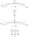
도 4는 시청자 위주의 동작 예시도 이다.FIG. 4 is a diagram illustrating an example of the operation of the viewer.
도 1 및 도 4의 (a)와 같이, 실시예에 따른 유연한 표시장치는 영상이 표시되는 유연한 표시패널(150)이 한 명의 시청자(USR1)가 위치하는 방향으로 구부러진다. 이때, 유연한 표시패널(150)은 한 명의 시청자(USR1)가 위치하는 조건에 따라 평편형에서 오목형으로 곡면을 형성한다.1 and 4A, in the flexible display device according to the embodiment, the
도 1 및 도 4의 (b)와 같이, 실시예에 따른 유연한 표시장치는 영상이 표시되는 유연한 표시패널(150)이 여러 명의 시청자(USR1 ~ USR3)가 위치하는 방향으로 구부러진다. 이때, 유연한 표시패널(150)은 여러 명의 시청자(USR1 ~ USR3)가 위치하는 조건에 따라 평편형에서 오목형으로 곡면을 형성한다.As shown in FIGS. 1 and 4B, in the flexible display device according to the embodiment, the
이와 같은 동작을 하기 위해 감지부(160)는 시청자(USR1)의 위치를 감지하고 감지 데이터(SD)를 곡면신호 생성부(170)에 공급한다. 곡면신호 생성부(170)는 감지 데이터(SD)를 기반으로 제1곡면신호(+RC)를 생성하고 이를 곡면 형성부(180)에 공급한다. 곡면 형성부(180)는 제1곡면신호(+RC)를 기반으로 유연한 표시패널(150)을 전면으로 구부린다.In order to perform such operation, the
여기서, 감지부(160)는 (1) 유연한 표시패널(150)과 시청자 간의 이격 거리 또는 (2) 시청자의 미간 거리와 같은 거리(DS)를 감지 데이터(SD)로 형성할 수 있다. 예컨대, 감지부(160)는 (1)에 해당하는 거리를 감지하기 위해 적외선 센서가 선택될 수 있다. 반면 감지부(160)는 (2)에 해당하는 거리를 감지하기 위해 카메라가 선택될 수 있다. 카메라를 이용한 시청자의 미간 거리 측정은 좌표값(x,y)이 이용될 수 있으나 이에 한정되지 않는다.Here, the
한편, 실시예에 따른 유연한 표시장치는 유연한 표시패널(150)을 시청하는 시청자의 수에 따라 곡면을 형성하는 곡률 반경의 차가 발생할 수 있다. 즉, 도 4의 (a)의 조건에서 생성된 제1곡면신호(+RC)와 도 4의 (b)의 조건에서 생성된 제1곡면신호(+RC)는 비동일하다.On the other hand, in the flexible display device according to the embodiment, a difference in curvature radius that forms a curved surface may occur depending on the number of viewers watching the
도 5는 주변 밝기 위주의 동작 예시도 이다.FIG. 5 is a diagram illustrating an example of operation around the brightness.
도 1 및 도 5의 (a)와 같이, 실시예에 따른 유연한 표시장치는 영상이 표시되는 유연한 표시패널(150)이 한 명의 시청자(USR1)가 위치하는 방향으로 구부러진다. 이때, 유연한 표시패널(150)은 주변 밝기(L)(달리 설명하면 조명, 외광 등에 의한 조도차)에 따라 평편형에서 오목형으로 곡면을 형성한다.As shown in FIGS. 1 and 5A, in the flexible display device according to the embodiment, the
도 1 및 도 5의 (b)와 같이, 실시예에 따른 유연한 표시장치는 영상이 표시되는 유연한 표시패널(150)이 여러 명의 시청자(USR1 ~ USR3)가 위치하는 방향으로 구부러진다. 이때, 유연한 표시패널(150)은 주변 밝기(L)에 따라 평편형에서 오목형으로 곡면을 형성한다.As shown in FIGS. 1 and 5B, in the flexible display device according to the embodiment, the
이와 같은 동작을 하기 위해 감지부(160)는 주변 밝기(L)를 감지하고 감지 데이터(SD)를 곡면신호 생성부(170)에 공급한다. 곡면신호 생성부(170)는 감지 데이터(SD)를 기반으로 제1곡면신호(+RC)를 생성하고 이를 곡면 형성부(180)에 공급한다. 곡면 형성부(180)는 제1곡면신호(+RC)를 기반으로 유연한 표시패널(150)을 전면으로 구부린다.In order to perform such operation, the
여기서, 감지부(160)는 주변 밝기(L)는 물론 (1) 유연한 표시패널(150)과 시청자 간의 이격 거리 또는 (2) 시청자의 미간 거리와 같은 거리(DS)를 감지 데이터로 형성할 수 있다. 예컨대, 감지부(160)는 주변 밝기(L)와 더불어 (1) 또는 (2)에 해당하는 거리를 감지하기 위해 카메라와 적외선 센서가 선택될 수 있다.Here, the
한편, 실시예에 따른 유연한 표시장치는 유연한 표시패널(150)의 주변 밝기(L) 및 유연한 표시패널(150)을 시청하는 시청자의 수에 따라 곡면을 형성하는 곡률 반경의 차가 발생할 수 있다. 즉, 도 5의 (a)의 조건에서 생성된 제1곡면신호(+RC)와 도 5의 (b)의 조건에서 생성된 제1곡면신호(+RC)는 비동일하다.Meanwhile, in the flexible display device according to the embodiment, a difference in radius of curvature that forms a curved surface may be generated depending on the ambient brightness L of the
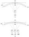
도 6은 영상의 종류 위주의 동작 예시도 이다.6 is a diagram illustrating an operation of the image type.
도 1 및 도 6의 (a)와 같이, 실시예에 따른 유연한 표시장치는 영상이 표시되는 유연한 표시패널(150)이 한 명의 시청자(USR1)가 위치하는 방향으로 구부러진다. 이때, 유연한 표시패널(150)은 영상의 종류(IMG)에 따라 평편형에서 오목형으로 곡면을 형성한다.1 and 6A, in the flexible display device according to the embodiment, the
도 1 및 도 6의 (b)와 같이, 실시예에 따른 유연한 표시장치는 영상이 표시되는 유연한 표시패널(150)이 여러 명의 시청자(USR1 ~ USR3)가 위치하는 방향으로 구부러진다. 이때, 유연한 표시패널(150)은 영상의 종류(IMG)에 따라 평편형에서 오목형으로 곡면을 형성한다.As shown in FIGS. 1 and 6 (b), in the flexible display device according to the embodiment, the
이와 같은 동작을 하기 위해 곡면신호 생성부(170)는 영상의 종류(IMG)를 감지하고 감지 데이터(SD)를 곡면신호 생성부(170)에 공급한다. 곡면신호 생성부(170)는 감지 데이터(SD)를 기반으로 제1곡면신호(+RC)를 생성하고 이를 곡면 형성부(180)에 공급한다. 곡면 형성부(180)는 제1곡면신호(+RC)를 기반으로 유연한 표시패널(150)을 전면으로 구부린다.In order to perform such operation, the curved
여기서, 감지부(160)는 영상의 종류(IMG)는 물론 (1) 유연한 표시패널(150)과 시청자 간의 이격 거리 또는 (2) 시청자의 미간 거리와 같은 거리(DS)를 감지 데이터(SD)로 형성할 수 있다. 예컨대, 감지부(160)는 영상의 종류(IMG)와 더불어 (1) 또는 (2)에 해당하는 거리를 감지하기 위해 카메라와 적외선 센서가 선택될 수 있다.Here, the
한편, 실시예에 따른 유연한 표시장치는 유연한 표시패널(150)에 표시되는 영상의 종류(IMG) 및 유연한 표시패널(150)을 시청하는 시청자의 수에 따라 곡면을 형성하는 곡률 반경의 차가 발생할 수 있다. 즉, 도 6의 (a)의 조건에서 생성된 제1곡면신호(+RC)와 도 6의 (b)의 조건에서 생성된 제1곡면신호(+RC)는 비동일하다.On the other hand, in the flexible display device according to the embodiment, the difference in the radius of curvature forming the curved surface may occur depending on the type of image (IMG) displayed on the
도 7은 영상의 종류 및 시청자 위주의 동작 예시도 이다.Fig. 7 is a diagram illustrating the types of images and the operation of the viewer-oriented operation.
도 1 및 도 7과 같이, 실시예에 따른 유연한 표시장치는 영상이 표시되는 유연한 표시패널(150)이 여러 명의 시청자(USR1 ~ USR4)가 위치하는 방향과 반대되는 방향으로 구부러진다. 이때, 유연한 표시패널(150)은 여러 명의 시청자(USR1 ~ USR4)가 각기 다른 영상을 시청할 수 있도록 영상의 종류(IMG1, IMG2) 및 시청자(USR1 ~ USR4)의 위치에 따라 평편형에서 볼록형으로 곡면을 형성한다.As shown in FIGS. 1 and 7, in the flexible display device according to the embodiment, the
이와 같은 동작을 하기 위해 곡면신호 생성부(170)는 영상의 종류(IMG1, IMG2)를 감지하고 감지 데이터(SD)를 곡면신호 생성부(170)에 공급한다. 곡면신호 생성부(170)는 감지 데이터(SD)를 기반으로 제2곡면신호(-RC)를 생성하고 이를 곡면 형성부(180)에 공급한다. 곡면 형성부(180)는 제2곡면신호(-RC)를 기반으로 유연한 표시패널(150)을 후면으로 구부린다.In order to perform such operation, the curved
여기서, 감지부(160)는 영상의 종류(IMG1, IMG2)는 물론 (1) 유연한 표시패널(150)과 시청자 간의 이격 거리 또는 (2) 시청자의 미간 거리와 같은 거리(DS)를 감지 데이터(SD)로 형성할 수 있다.The
한편, 실시예에 따른 유연한 표시장치는 유연한 표시패널(150)에 표시되는 영상의 종류(IMG1, IMG2) 및 유연한 표시패널(150)을 시청하는 시청자의 위치에 따라 곡면을 형성하는 곡률 반경의 차가 발생할 수 있다.Meanwhile, in the flexible display device according to the embodiment, the difference between the types of images IMG1 and IMG2 displayed on the
앞서 설명된 바와 같이, 실시예에 따른 유연한 표시장치를 구성하는 곡면 형성부(180)는 곡면신호에 대응하여 유연한 표시패널(150)의 중심점을 기준으로 나누어진 좌측 지점과 우측 지점을 구부렸다 피거나 중심점을 구부렸다 피는 동작을 수행한다.As described above, the curved
위와 같은 동작을 수행하는 곡면 형성부(180)는 기구부 및 구동부로 형성된다. 기구부는 유연한 표시패널(150)을 고정하는 역할을 하고 구동부는 기구부와 더불어 유연한 표시패널(150)을 구부리는 역할을 한다. 이와 같이 곡면 형성부(180)는 기구적인 장치를 요구하므로 이의 동작에 의해 유연한 표시패널(150)의 파손이나 손상이 따를 수 있다. 따라서, 곡면 형성부(180)의 동작에 의한 파손이나 손상을 방지하기 위해 유연한 표시패널(150)은 다음과 같이 구성될 수 있다.The curved
도 8은 실시예에 따른 유연한 표시패널의 구성도이다.8 is a configuration diagram of a flexible display panel according to an embodiment.
도 8에 도시된 바와 같이, 실시예에 따른 유연한 표시패널(150)에는 영상을 표시하는 표시패널(151)과 표시패널(151)의 후면에 부착된 후면커버(155)가 포함된다. 표시패널(151)과 후면커버(155)는 평평한 상태를 유지한 상태에서 부착된다. 후면커버(155)는 열전도율과 연성을 가진 재료를 이용할 수 있는데 이에 대한 구체적인 설명은 후술한다.As shown in FIG. 8, the
이하, 곡면 형성부의 구성 및 동작에 대해 설명한다.Hereinafter, the configuration and operation of the curved surface forming portion will be described.
도 9는 본 발명의 제1실시예에 따른 곡면 형성부의 구성도이고, 도 10은 도 9에 도시된 구동부의 동작을 설명하기 위한 도면이다.FIG. 9 is a configuration diagram of a curved surface forming unit according to the first embodiment of the present invention, and FIG. 10 is a view for explaining the operation of the driving unit shown in FIG.
도 9에 도시된 바와 같이, 곡면 형성부(181 ~ 185)에는 와이어(181, 182), 지지대(183a, 183b), 고정자(184) 및 구동부(185)가 포함된다. 와이어(181, 182)는 유연한 표시패널(150)의 후면 좌측 지점과 우측 지점에 구분되어 설치된다. 지지대(183a, 183b)는 와이어(181, 182)에 형성된 장력이 유연한 표시패널(150)에 효율적으로 전달되도록 유연한 표시패널(150)의 좌우측에 설치된다. 고정자(184)는 와이어(181, 182)가 안정적으로 고정되도록 유연한 표시패널(150)의 후면 하단에 설치된다. 구동부(185)는 곡면신호에 대응하여 자신의 길이를 가변하여 와이어(181, 182)에 장력이 형성되도록 유연한 표시패널(150)의 후면에 설치된다.9,
도 10에 도시된 바와 같이, 구동부(185)는 모터 방식, 공기 압력 방식, 유체 압력 방식 등과 같이 자신의 길이를 가변할 수 있는 장치로 구성된다. 구동부(185)가 모터 방식인 경우, 이는 모터의 회전 방향에 따라 나사의 길이를 늘이거나 줄여 자신의 길이를 가변하게 된다. 구동부(185)가 공기 압력 방식인 경우, 이는 공기 압력에 따라 나사의 길이를 늘이거나 줄여 자신의 길이를 가변하게 된다. 구동부(185)가 유체 압력 방식인 경우, 이는 유체 압력에 따라 나사의 길이를 늘이거나 줄여 자신의 길이를 가변하게 된다. 이 밖에, 구동부(185)는 자신의 길이를 가변할 수 있는 다양한 장치로 구성될 수 있다.As shown in FIG. 10, the driving
도 9 및 도 10과 같이 곡면신호 생성부로부터 제1곡면신호가 공급되면, 구동부(185)는 x2 방향(x2)으로 구동을 하면서 자신의 길이를 늘이게 된다. 이때, 와이어(181, 182)는 구동부(185)의 길이가 늘어남에 따라 미는 힘을 형성하게 된다. 그러면, 유연한 표시패널(150)은 도 9의 (a)와 같이 평면형에서 도 9의 (b)와 같이 오목형으로 곡면을 형성하게 된다.When the first curved surface signal is supplied from the curved surface signal generating unit as shown in FIGS. 9 and 10, the driving
이와 달리, 곡면신호 생성부로부터 제2곡면신호가 공급되면, 구동부(185)는 x1 방향(x1)으로 구동을 하면서 자신의 길이를 줄이게 된다. 이때, 와이어(181, 182)는 구동부(185)의 길이가 줄어들게 됨에 따라 당기는 힘을 형성하게 된다. 그러면, 유연한 표시패널(150)은 도 9의 (a)와 같이 평면형에서 도 9의 (c)와 같이 볼록형으로 곡면을 형성하게 된다.Alternatively, when the second curved surface signal is supplied from the curved surface signal generation unit, the driving
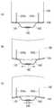
도 11은 본 발명의 제2실시예에 따른 곡면 형성부의 구성도이고, 도 12는 도 10에 도시된 구동부의 동작을 설명하기 위한 도면이다.FIG. 11 is a configuration diagram of a curved surface forming unit according to a second embodiment of the present invention, and FIG. 12 is a view for explaining the operation of the driving unit shown in FIG.
도 11에 도시된 바와 같이, 곡면 형성부(185, 187)에는 지지대(186, 187)와 구동부(185)가 포함된다. 지지대(186, 187)는 유연한 표시패널(150)의 후면 좌측 지점과 우측 지점에 구분되어 설치된다. 구동부(185)는 곡면신호에 대응하여 지지대(186, 187)를 구부리도록 유연한 표시패널(150)의 후면 중심점에 일부가 고정된 고정자(185a)를 갖고 "ㅗ"자 형태(또는 T자 형태)로 설치된다.As shown in FIG. 11, the curved
도 12에 도시된 바와 같이, 구동부(185)는 모터 방식 등으로 지지대(186)를 구부리거나 필 수 있는 관절 접이식 장치로 구성된다. 이 밖에, 구동부(185)는 지지대(186)를 구부리거나 필 수 있는 다양한 장치로 구성될 수 있다.As shown in FIG. 12, the driving
도 11 및 도 12와 같이 곡면신호 생성부로부터 제1곡면신호가 공급되면, 구동부(185)는 x2 방향(x2)으로 구동을 하면서 지지대(186, 187)의 각(r)을 좁히게 된다. 이때, 지지대(186, 187)는 각(r)이 좁아짐에 따라 미는 힘을 형성하게 된다. 그러면, 유연한 표시패널(150)은 도 11의 (a)와 같이 평면형에서 도 11의 (b)와 같이 오목형으로 곡면을 형성하게 된다.When the first curved surface signal is supplied from the curved surface signal generation unit as shown in FIGS. 11 and 12, the driving
이와 달리, 곡면신호 생성부로부터 제2곡면신호가 공급되면, 구동부(185)는 x1 방향(x1)으로 구동을 하면서 지지대(186, 187)의 각(r)을 넓히게 된다. 이때, 지지대(186, 187)는 각(r)이 넓어짐에 따라 당기는 힘을 형성하게 된다. 그러면, 유연한 표시패널(150)은 도 11의 (a)와 같이 평면형에서 도 11의 (c)와 같이 볼록형으로 곡면을 형성하게 된다.Alternatively, when the second curved surface signal is supplied from the curved surface signal generation unit, the driving
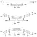
도 13은 본 발명의 제3실시예에 따른 곡면 형성부의 구성도이고, 도 14는 도 13에 도시된 구동부의 동작을 설명하기 위한 도면이다.FIG. 13 is a configuration diagram of a curved surface forming unit according to a third embodiment of the present invention, and FIG. 14 is a view for explaining the operation of the driving unit shown in FIG.
도 13에 도시된 바와 같이, 곡면 형성부(185, 187)에는 지지대(188)와 구동부(189a, 189b)가 포함된다. 지지대(188)는 유연한 표시패널(150)의 중심점에 일부가 고정된 고정자(188a)를 갖도록 "ㅗ"자 형태(또는 T자 형태)로 설치된다. 구동부(189a, 189b)는 곡면신호에 대응하여 자신의 길이를 가변하도록 유연한 표시패널(150)의 후면 좌측 지점과 우측 지점에 대응되는 지지대(188)에 구분되어 수직으로 설치된다.As shown in Fig. 13, the curved
도 14에 도시된 바와 같이, 구동부(189a)는 모터 방식, 공기 압력 방식, 유체 압력 방식 등과 같이 자신의 길이를 가변할 수 있는 장치로 구성된다. 구동부(189a)가 모터 방식인 경우, 이는 모터의 회전 방향에 따라 나사의 길이를 늘이거나 줄여 자신의 길이를 가변하게 된다. 구동부(189a)가 공기 압력 방식인 경우, 이는 공기 압력에 따라 나사의 길이를 늘이거나 줄여 자신의 길이를 가변하게 된다. 구동부(189a)가 유체 압력 방식인 경우, 이는 유체 압력에 따라 나사의 길이를 늘이거나 줄여 자신의 길이를 가변하게 된다. 이 밖에, 구동부(189a)는 자신의 길이를 가변할 수 있는 다양한 장치로 구성될 수 있다.As shown in FIG. 14, the
도 13 및 도 14와 같이 곡면신호 생성부로부터 제1곡면신호가 공급되면, 구동부(189a, 189b)는 y2 방향(y2)으로 구동을 하면서 자신의 길이를 늘이게 된다. 이때, 구동부(189a, 189b)는 자신의 길이가 늘어남에 따라 미는 힘을 형성하게 된다. 그러면, 유연한 표시패널(150)은 도 13의 (a)와 같이 평면형에서 도 13의 (b)와 같이 오목형으로 곡면을 형성하게 된다.When the first curved surface signal is supplied from the curved surface signal generation unit as shown in FIGS. 13 and 14, the driving
이와 달리, 곡면신호 생성부로부터 제2곡면신호가 공급되면, 구동부(189a, 189b)는 y1 방향(y1)으로 구동을 하면서 자신의 길이를 줄이게 된다. 이때, 구동부(189a, 189b)는 자신의 길이가 줄어들게 됨에 따라 당기는 힘을 형성하게 된다. 그러면, 유연한 표시패널(150)은 도 13의 (a)와 같이 평면형에서 도 13의 (c)와 같이 볼록형으로 곡면을 형성하게 된다.In contrast, when the second curved surface signal is supplied from the curved surface signal generation unit, the driving
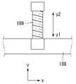
도 15는 본 발명의 제4실시예에 따른 곡면 형성부의 구성도이고, 도 16은 도 15에 도시된 구동부의 동작을 설명하기 위한 도면이며, 도 17은 도 15에 도시된 지지대와 구동부의 설치 예시도 이다.FIG. 15 is a configuration diagram of a curved surface forming unit according to a fourth embodiment of the present invention, FIG. 16 is a view for explaining the operation of the driving unit shown in FIG. 15, Fig.
도 15에 도시된 바와 같이, 곡면 형성부(185, 187)에는 지지대(188)와 구동부(189)가 포함된다. 지지대(188)는 유연한 표시패널(150)의 후면 좌측 지점과 우측 지점에 구분되어 설치된 고정자(188a, 188b)를 갖도록 "ㄷ"자 형태(또는 한 쌍의 L자로 조합된 형태)로 설치된다. 구동부(189)는 곡면신호에 대응하여 자신의 길이를 가변하도록 유연한 표시패널(150)의 후면 중심점에 대응되는 지지대(188)에 수직으로 설치된다.As shown in FIG. 15, the curved
도 16에 도시된 바와 같이, 구동부(189)는 모터 방식, 공기 압력 방식, 유체 압력 방식 등과 같이 자신의 길이를 가변할 수 있는 장치로 구성된다. 구동부(189)가 모터 방식인 경우, 이는 모터의 회전 방향에 따라 나사의 길이를 늘이거나 줄여 자신의 길이를 가변하게 된다. 구동부(189)가 공기 압력 방식인 경우, 이는 공기 압력에 따라 나사의 길이를 늘이거나 줄여 자신의 길이를 가변하게 된다. 구동부(189)가 유체 압력 방식인 경우, 이는 유체 압력에 따라 나사의 길이를 늘이거나 줄여 자신의 길이를 가변하게 된다. 이 밖에, 구동부(189)는 자신의 길이를 가변할 수 있는 다양한 장치로 구성될 수 있다.As shown in FIG. 16, the driving
15 및 도 16과 같이 곡면신호 생성부로부터 제2곡면신호가 공급되면, 구동부(189)는 y1 방향(y1)으로 구동을 하면서 자신의 길이를 줄이게 된다. 이때, 구동부(189)는 자신의 길이가 줄어들게 됨에 따라 당기는 힘을 형성하게 된다. 그러면, 유연한 표시패널(150)은 도 15의 (a)와 같이 평면형에서 도 15의 (b)와 같이 오목형으로 곡면을 형성하게 된다.When the second curved surface signal is supplied from the curved surface signal generation unit as shown in FIGS. 15 and 16, the driving
이와 달리, 곡면신호 생성부로부터 제1곡면신호가 공급되면, 구동부(189)는 y2 방향(y2)으로 구동을 하면서 자신의 길이를 늘이게 된다. 이때, 구동부(189)는 자신의 길이가 늘어나게 됨에 따라 미는 힘을 형성하게 된다. 그러면, 유연한 표시패널(150)은 도 15의 (a)와 같이 평면형에서 도 15의 (c)와 같이 볼록형으로 곡면을 형성하게 된다.Alternatively, when the first curved surface signal is supplied from the curved surface signal generation unit, the driving
한편, 고정자(188a, 188b)를 갖는 지지대(188)와 구동부(189)는 도 17에 도시된 바와 같이 유연한 표시패널(150)에 가해지는 힘을 용이하게 전달할 수 있도록 다수로 설치된다. 이는 제4실시예뿐만 아니라 제2 및 제3실시예의 구조에도 적용된다.On the other hand, the
앞서 설명된 유연한 표시패널(150)은 연성이 있지만 내부에 형성된 소자를 보호하는 기판의 재질에 따라 그리고 곡률 반경에 따라 파손의 가능성이 있다. 따라서, 유연한 표시패널(150)에 가할 수 있는 최대 곡률 반경 벗어나지 않도록 유연한 표시패널(150)의 구조를 설정하거나 곡면 형성부의 구조를 설정할 수 있다. 예컨대, 곡면 형성부의 경우 유연한 표시패널(150)과 맞닿는 지지대나 구동부의 부분에 충격을 최소화할 수 있는 쿠션 등의 재질을 더 부착할 수 있다. 반면 유연한 표시패널(150)의 경우 다음과 같이 구성될 수 있다.Although the
이하, 유연한 표시패널(150)의 파손 가능성을 방지하기 위한 구조에 대해 설명한다.Hereinafter, a structure for preventing the possibility of breakage of the
도 18은 유연한 표시패널에 부착된 후면커버의 평면도이고, 도 19는 도 18에 도시된 후면커버의 예시도 이다.18 is a plan view of a rear cover attached to a flexible display panel, and Fig. 19 is an illustration of a rear cover shown in Fig.
도 18에 도시된 바와 같이, 후면커버(155)는 유연한 표시패널이 장축방향(x)으로 쉽게 구부러지고 단축방향(y)으로 구부러지지 않도록 구성된다. 이를 위해, 후면커버(155)에는 표시패널의 후면에 부착된 기재판(155a)과, 기재판(155a)의 일면에 형성되고 단축방향(y)으로 이격되어 스트라이프 형태를 이루는 비드(155b)가 포함된다.As shown in Fig. 18, the
비드(155b)는 기재판(155a)의 일면에 단축방향(y)으로 이격되어 다수의 스트라이프 형태를 이루므로 단축방향(y)으로 구부러지지 않도록 표시패널을 지지할 수 있게 된다.The
비드(155b)의 모서리부는 도 19의 (a)와 같이 직각 형상을 갖거나 도 19의 (b)와 같이 라운드 형상을 가질 수 있다. 직각 형상을 갖는 비드(155b)는 강한 강성과 더불어 우수한 가공성을 제공할 수 있다. 이와 달리, 라운드 형상을 갖는 비드(155b)는 반복적인 곡률 형성에 따른 모서리부의 피로도 축적을 낮출 수 있다. 또한, 라운드 형상을 갖는 비드(155b)는 표면뿐만 아니라 기재판(155a)과 부착된 부착면 또한 라운드 형상을 이루므로 곡면 형성시 부착면에 형성되는 응력을 낮출 수 있다.The corner of the
한편, 비드(155b)를 형성할 때에는 유연한 표시패널이 중심을 기준으로 구부러지도록 다음과 같이 설치할 수 있다. 먼저, 기재판(155a)의 중심점에 비드(155b)의 중심점이 일치되도록(또는 기재판의 중심점과 두 개의 비드의 사이에 위치하는 중심점이 일치되도록) 설치한다. 그리고 기재판(155a)의 양쪽 끝지점에 비드(155b)가 각각 위치하도록 설치한다.On the other hand, when the
후면커버(155)를 구성하는 재료는 효율적인 방열을 위해 열전도율과 연성을 가진 알루미늄(Al 5052 계열) 또는 열전도성 플라스틱을 이용할 수 있으나 이에 한정되지 않는다. 후면커버(155)를 구성하는 재료의 두께는 얇을수록 좋으나 강성을 고려하여 최소 1.0㎜ 이상으로 형성하는 것이 바람직하다. 여기서, 알루미늄은 전기아연도금강판(EGI)이나 철-니켈-크롬의 주조합금 금속(Inconel) 등의 금속물보다 밀도가 작기 때문에 중량을 감소시킬 수 있다. 반면, 플라스틱은 디자인의 자율성을 높일 수 있고 알루미늄 등과 같은 금속대비 가벼운 중량으로 구현이 가능하다.The material of the
앞서 설명된 유연한 표시장치는 유연한 표시패널이 오목하게 또는 볼록하게 구부러진다. 유연한 표시장치가 대화면으로 구성될 때, 유연한 표시패널에 형성되는 곡면을 보다 안정적으로 형성하기 위해서는 유연한 표시패널에 부착되는 구동장치의 배치를 다음과 같이 구성할 수 있다.The flexible display device described above has a flexible display panel bent concavely or convexly. In order to more reliably form the curved surface formed on the flexible display panel when the flexible display device is configured as a large surface, the arrangement of the driving device attached to the flexible display panel can be configured as follows.
이하, 유연한 표시장치를 구현하기 위한 구동장치의 배치에 대해 설명한다.Hereinafter, the arrangement of the driving apparatus for implementing a flexible display apparatus will be described.
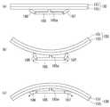
도 20은 유연한 표시장치를 구현하기 위한 구동장치의 배치 예시도 이다.20 is a diagram showing an example of the arrangement of a driving device for implementing a flexible display device.
도 20의 (a)와 같이, 유연한 표시패널(150)에는 유연한 표시패널(150)에 데이터 신호를 공급하는 데이터 구동부(130)가 실장된 다수의 제1외부회로기판(131)과, 다수의 제1외부회로기판(131)에 부착된 N개(N은 2 이상 정수)의 제2외부회로기판(135)이 포함된다. 다수의 제1외부회로기판(131)은 유연한 표시패널(150)의 장축방향을 따라 부착되며, N개의 제2외부회로기판(135)은 유연한 표시패널(150)이 구부러지는 중심점을 기준으로 분할 배치된다.20A, a
위와 같은 장치를 유연한 표시패널(150)에 부착 및 배치하는 방법은 다음과 같다.A method of attaching and arranging the above apparatus to the
유연한 표시패널(150)에 데이터 신호를 공급하는 다수의 데이터 구동부(130)를 다수의 제1외부회로기판(131)에 각각 실장한다. 그리고 다수의 제1외부회로기판(131)을 유연한 표시패널(150)의 장축방향을 따라 부착한다. 그리고 유연한 표시패널(150)이 구부러지는 중심점을 기준으로 제2외부회로기판(135)을 N개(N은 2 이상 정수)로 분할하여 배치하고 다수의 제1외부회로기판(131)에 부착한다.A plurality of
이와 같이, 제1외부회로기판(131) 및 제2외부회로기판(135)을 배치하면 이들을 유연한 표시패널(150)의 후면에 부착하더라도 곡면 형성에 의해 유연한 표시패널(150)이나 제1외부회로기판(131) 및 제2외부회로기판(135)이 파손되는 문제는 방지된다. 여기서, 제1외부회로기판(131)은 인쇄회로기판으로 선택되는 반면 제2외부회로기판(135)은 연성회로기판으로 선택될 수 있다.If the first
도 20의 (b)와 같이, 제1외부회로기판(131)은 유연한 표시패널(150)의 단축방향을 따라 좌우측에 분할 부착되며, N개의 제2외부회로기판(135)은 유연한 표시패널의 좌우측으로 분할 배치된다.20B, the first
위와 같은 장치를 유연한 표시패널(150)에 부착 및 배치하는 방법은 다음과 같다.A method of attaching and arranging the above apparatus to the
유연한 표시패널(150)에 데이터 신호를 공급하는 다수의 데이터 구동부(130)를 다수의 제1외부회로기판(131)에 각각 실장한다. 그리고 다수의 제1외부회로기판(131)을 유연한 표시패널(150)의 단축방향을 따라 좌우측에 분할하여 부착한다. 그리고 제2외부회로기판(135)을 N개(N은 2 이상 정수)로 분할하여 유연한 표시패널(150)의 좌우측에 배치하고 다수의 제1외부회로기판(131)에 부착한다.A plurality of
이와 같이, 제1외부회로기판(131) 및 제2외부회로기판(135)을 배치하면 이들을 유연한 표시패널(150)의 후면에 부착하더라도 곡면 형성에 의해 유연한 표시패널(150)이나 제1외부회로기판(131) 및 제2외부회로기판(135)이 파손되는 문제는 방지된다. 여기서, 제1외부회로기판(131)은 인쇄회로기판으로 선택되는 반면 제2외부회로기판(135)은 인쇄회로기판 또는 연성회로기판으로 선택될 수 있다.If the first
도 20에서 설명된 유연한 표시장치는 게이트 신호를 공급하는 게이트 구동부가 게이트인 패널 형태로 유연한 표시패널(150)에 형성된 것을 예로 한다.The flexible display device described with reference to FIG. 20 is an example in which the
앞서 설명된 본 발명은 시청자에게 최적의 시청감을 주기 위해 사용자 설정, 외부 환경 조건 및 내부 영상 조건 중 적어도 하나에 대응하여 유연한 표시패널에 수동 또는 자동으로 곡면을 형성할 수 있는 효과가 있다. 또한, 본 발명은 유연한 표시패널에 부착되는 외부회로기판의 배치를 달리하여 곡면을 안정적으로 형성할 수 있는 효과가 있다. 또한, 본 발명은 유연한 표시패널의 후면에 후면커버를 설치하여 강성을 확보할 수 있음은 물론 응력 집중이나 피로 파괴 등과 같은 문제를 방지할 수 있는 효과가 있다. 또한, 본 발명은 후면커버의 디자인 자유도를 높일 수 있음 물론 가벼운 중량으로 구현 가능한 효과가 있다. 또한, 본 발명은 기구적인 장치를 기반으로 구부러지거나 펴지므로 유연한 표시패널이 최대 곡률 반경 이하에서 안정적으로 동작 가능한 효과가 있다. 또한, 본 발명은 유연한 표시패널과 후면커버를 평평한 상태에서 조립이 가능하므로 얼라인 불량을 최소화할 수 있는 효과가 있다.The present invention described above has an effect of manually or automatically forming a curved surface on a flexible display panel in correspondence with at least one of a user setting, an external environment condition, and an internal image condition in order to give an optimal viewing experience to a viewer. Further, the present invention has an effect of stably forming a curved surface by differently arranging an external circuit board attached to a flexible display panel. In addition, the present invention has the effect of preventing the problems such as stress concentration and fatigue breaking as well as ensuring rigidity by providing a rear cover on the back surface of the flexible display panel. In addition, the present invention can increase the degree of freedom of design of the rear cover, and can be implemented with a light weight. Further, since the present invention is bent or spread on the basis of a mechanical device, there is an effect that a flexible display panel can stably operate at a maximum radius of curvature or less. In addition, since the flexible display panel and the rear cover can be assembled in a flat state, the present invention has an effect of minimizing defective alignment.
이상 첨부된 도면을 참조하여 본 발명의 실시예를 설명하였지만, 상술한 본 발명의 기술적 구성은 본 발명이 속하는 기술 분야의 당업자가 본 발명의 그 기술적 사상이나 필수적 특징을 변경하지 않고서 다른 구체적인 형태로 실시될 수 있다는 것을 이해할 수 있을 것이다. 그러므로 이상에서 기술한 실시 예들은 모든 면에서 예시적인 것이며 한정적인 것이 아닌 것으로서 이해되어야 한다. 아울러, 본 발명의 범위는 상기 상세한 설명보다는 후술하는 특허청구범위에 의하여 나타내어진다. 또한, 특허청구범위의 의미 및 범위 그리고 그 등가 개념으로부터 도출되는 모든 변경 또는 변형된 형태가 본 발명의 범위에 포함되는 것으로 해석되어야 한다.
While the present invention has been described in connection with what is presently considered to be practical exemplary embodiments thereof, it is to be understood that the invention is not limited to the disclosed embodiments, but, on the contrary, It will be understood that the invention may be practiced. It is therefore to be understood that the embodiments described above are to be considered in all respects only as illustrative and not restrictive. In addition, the scope of the present invention is indicated by the following claims rather than the detailed description. Also, all changes or modifications derived from the meaning and scope of the claims and their equivalents should be construed as being included within the scope of the present invention.
110: 영상 보드부120: 타이밍 제어부
130: 데이터 구동부140: 게이트 구동부
150: 유연한 표시패널160: 감지부
170: 곡면신호 생성부180: 곡면 형성부
155: 후면커버110: video board 120: timing controller
130: Data driver 140: Gate driver
150: Flexible display panel 160:
170: Curved surface signal generating unit 180: Curved surface forming unit
155: Rear cover
Claims (11)
Translated fromKorean상기 유연한 표시패널의 표시면을 평면 또는 곡면으로 형성하는 곡면 형성부; 및
상기 표시면의 곡률 반경이 사용자 설정, 외부 환경 조건 및 내부 영상 조건 중 적어도 하나에 대응하여 제어되도록 상기 곡면 형성부에 곡면신호를 공급하는 곡면신호 생성부를 포함하고,
상기 곡면 형성부는 상기 곡면신호에 대응하여 상기 유연한 표시패널의 곡면을 오목하게 형성하거나 볼록하게 형성하는 유연한 표시장치.Flexible display panel;
A curved surface forming part forming a display surface of the flexible display panel in a plane or a curved surface; And
And a curved surface signal generating unit for supplying a curved surface signal to the curved surface forming unit so that a radius of curvature of the display surface is controlled according to at least one of a user setting, an external environment condition, and an internal image condition,
Wherein the curved surface forming portion concavely or convexly forms a curved surface of the flexible display panel corresponding to the curved surface signal.
상기 곡면 형성부는
상기 곡면신호에 대응하여 상기 유연한 표시패널의 중심점을 기준으로 나누어진 좌측 지점과 우측 지점을 구부렸다 피거나 상기 중심점을 구부렸다 피는 것을 특징으로 하는 유연한 표시장치.The method according to claim 1,
The curved surface forming portion
Wherein the flexible display panel flexes or bends the left and right divided points based on the center point of the flexible display panel corresponding to the curved surface signal.
상기 외부 환경 조건은 상기 유연한 표시패널을 시청하는 시청자의 위치, 상기 시청자의 수, 상기 시청자와 인접하는 최외곽 시청자의 위치, 상기 시청자와 가장 인접한 다른 시청자의 위치 및 상기 유연한 표시패널의 주변 밝기 중 적어도 하나를 포함하고,
상기 내부 영상 조건은 상기 유연한 표시패널에 표시되는 영상의 종류를 포함하는 유연한 표시장치.The method according to claim 1,
Wherein the external environmental condition includes at least one of a position of a viewer watching the flexible display panel, a number of viewers, a position of an outermost viewer adjacent to the viewer, a position of another viewer closest to the viewer, At least one,
Wherein the internal image condition includes a type of an image displayed on the flexible display panel.
상기 곡면 형성부는
상기 유연한 표시패널의 후면 좌측 지점과 우측 지점에 구분되어 설치된 와이어와,
상기 와이어의 장력이 가변 되도록 상기 곡면신호에 대응하여 자신의 길이를 가변하는 구동부를 포함하는 유연한 표시장치.The method according to claim 1,
The curved surface forming portion
A wire provided separately from a rear left side point and a right side point of the flexible display panel,
And a driver for varying a length of the wire corresponding to the curved surface signal so that a tension of the wire is variable.
상기 곡면 형성부는
상기 유연한 표시패널의 후면 좌측 지점과 우측 지점에 구분되어 설치된 지지대와,
상기 유연한 표시패널의 후면 중심점에 일부가 고정된 고정자를 가지며 상기 곡면신호에 대응하여 상기 지지대를 구부렸다 피는 구동부를 포함하는 유연한 표시장치.The method according to claim 1,
The curved surface forming portion
A support stand separated from a rear left side point and a right side point of the flexible display panel,
And a driving unit having a stator partly fixed to a rear center point of the flexible display panel and bending and supporting the support member corresponding to the curved surface signal.
상기 곡면 형성부는
상기 유연한 표시패널의 후면 중심점에 일부가 고정된 고정자를 갖는 지지대와,
상기 유연한 표시패널의 후면 좌측 지점과 우측 지점에 대응되는 상기 지지대에 수직으로 구분되어 설치되고 상기 곡면신호에 대응하여 자신의 길이를 가변하는 구동부를 포함하는 유연한 표시장치.The method according to claim 1,
The curved surface forming portion
A support having a stator partly fixed to a rear center point of the flexible display panel;
And a driving unit installed vertically on the supporting base corresponding to a rear left point and a right point of the flexible display panel and varying a length of the curved surface signal corresponding to the curved surface signal.
상기 곡면 형성부는
상기 유연한 표시패널의 후면 좌측 지점과 우측 지점에 구분되어 설치된 고정자를 갖는 지지대와,
상기 유연한 표시패널의 후면 중심점에 대응되는 상기 지지대에 수직으로 설치되고 상기 곡면신호에 대응하여 자신의 길이를 가변하는 구동부를 포함하는 유연한 표시장치.The method according to claim 1,
The curved surface forming portion
A support having a stator provided at a rear left side point and a right side point of the flexible display panel,
And a driving unit vertically installed on the supporter corresponding to a rear center point of the flexible display panel and varying its length in accordance with the curved surface signal.
상기 유연한 표시패널은
영상을 표시하는 표시패널과, 상기 표시패널의 후면에 부착된 후면커버를 포함하며,
상기 후면커버는
상기 유연한 표시패널의 후면에 부착된 기재판과,
상기 기재판의 일면에 형성되고 단축방향으로 이격되어 스트라이프 형태를 이루는 비드를 포함하는 유연한 표시장치.The method according to claim 1,
The flexible display panel
A display panel for displaying an image; and a rear cover attached to the rear surface of the display panel,
The rear cover
A base plate attached to a rear surface of the flexible display panel,
And a bead formed on one surface of the base plate and spaced apart in the minor axis direction to form a stripe shape.
상기 비드는
모서리부가 직각 또는 라운드 형상을 갖는 것을 특징으로 하는 유연한 표시장치.9. The method of claim 8,
The bead
And the corner portion has a right angle or a round shape.
상기 유연한 표시패널은
상기 유연한 표시패널에 데이터 신호를 공급하는 데이터 구동부가 실장된 다수의 제1외부회로기판과,
상기 다수의 제1외부회로기판에 부착된 N개(N은 2 이상 정수)의 제2외부회로기판을 포함하되,
상기 다수의 제1외부회로기판은 상기 유연한 표시패널의 장축방향을 따라 부착되며,
상기 N개의 제2외부회로기판은 상기 유연한 표시패널이 구부러지는 중심점을 기준으로 분할 배치된 것을 특징으로 하는 유연한 표시장치.The method according to claim 1,
The flexible display panel
A plurality of first external circuit boards mounted with a data driver for supplying data signals to the flexible display panel,
And N second external circuit boards (N is an integer of two or more) attached to the plurality of first external circuit boards,
Wherein the plurality of first external circuit boards are attached along a major axis direction of the flexible display panel,
Wherein the N second external circuit boards are divided and arranged based on a center point at which the flexible display panel is bent.
상기 유연한 표시패널은
상기 유연한 표시패널에 데이터 신호를 공급하는 데이터 구동부가 실장된 다수의 제1외부회로기판과,
상기 다수의 제1외부회로기판에 부착된 N개(N은 2 이상 정수)의 제2외부회로기판을 포함하되,
상기 다수의 제1외부회로기판은 상기 유연한 표시패널의 단축방향을 따라 좌우측에 분할 부착되며,
상기 N개의 제2외부회로기판은 상기 유연한 표시패널의 좌우측으로 분할 배치된 것을 특징으로 하는 유연한 표시장치.The method according to claim 1,
The flexible display panel
A plurality of first external circuit boards mounted with a data driver for supplying data signals to the flexible display panel,
And N second external circuit boards (N is an integer of two or more) attached to the plurality of first external circuit boards,
The plurality of first external circuit boards are divided and attached to left and right sides along the minor axis direction of the flexible display panel,
Wherein the N second external circuit boards are divided into left and right sides of the flexible display panel.
Priority Applications (3)
| Application Number | Priority Date | Filing Date | Title |
|---|---|---|---|
| KR1020120014436AKR101507206B1 (en) | 2012-02-13 | 2012-02-13 | Flexible Display Device |
| CN201310047378.2ACN103247235B (en) | 2012-02-13 | 2013-02-06 | Flexible display |
| US13/762,566US9390642B2 (en) | 2012-02-13 | 2013-02-08 | Flexible display |
Applications Claiming Priority (1)
| Application Number | Priority Date | Filing Date | Title |
|---|---|---|---|
| KR1020120014436AKR101507206B1 (en) | 2012-02-13 | 2012-02-13 | Flexible Display Device |
Publications (2)
| Publication Number | Publication Date |
|---|---|
| KR20130092868A KR20130092868A (en) | 2013-08-21 |
| KR101507206B1true KR101507206B1 (en) | 2015-03-30 |
Family
ID=48926731
Family Applications (1)
| Application Number | Title | Priority Date | Filing Date |
|---|---|---|---|
| KR1020120014436AActiveKR101507206B1 (en) | 2012-02-13 | 2012-02-13 | Flexible Display Device |
Country Status (3)
| Country | Link |
|---|---|
| US (1) | US9390642B2 (en) |
| KR (1) | KR101507206B1 (en) |
| CN (1) | CN103247235B (en) |
Cited By (5)
| Publication number | Priority date | Publication date | Assignee | Title |
|---|---|---|---|---|
| KR20210001447A (en)* | 2019-06-28 | 2021-01-06 | 엘지디스플레이 주식회사 | Flexible display device |
| WO2021157881A1 (en)* | 2020-02-07 | 2021-08-12 | 주식회사 토비스 | Device for varying shape of display panel, and curved display apparatus equipped with same |
| KR102531119B1 (en)* | 2021-12-23 | 2023-05-10 | 엘지디스플레이 주식회사 | Flexible display device |
| KR20230096807A (en)* | 2021-12-23 | 2023-06-30 | 엘지디스플레이 주식회사 | Flexible display device |
| KR20230161176A (en)* | 2022-05-18 | 2023-11-27 | 엘지디스플레이 주식회사 | Display apparatus |
Families Citing this family (114)
| Publication number | Priority date | Publication date | Assignee | Title |
|---|---|---|---|---|
| KR20140117110A (en)* | 2013-03-26 | 2014-10-07 | 삼성디스플레이 주식회사 | Mobile device and method of operating a mobile device |
| US9536456B2 (en)* | 2013-07-02 | 2017-01-03 | Lg Electronics, Inc. | Image display device |
| KR101490301B1 (en)* | 2013-07-16 | 2015-02-04 | 황현준 | Flexible display panel bending system |
| KR20150012982A (en)* | 2013-07-25 | 2015-02-04 | 삼성전자주식회사 | Display apparatus and control method for the same |
| KR102111407B1 (en)* | 2013-08-19 | 2020-05-15 | 엘지전자 주식회사 | Display apparatus and method for operating the same |
| KR20150026028A (en) | 2013-08-30 | 2015-03-11 | 엘지전자 주식회사 | Image display device |
| US9496522B2 (en)* | 2013-12-13 | 2016-11-15 | Universal Display Corporation | OLED optically coupled to curved substrate |
| JP2015075516A (en)* | 2013-10-07 | 2015-04-20 | ソニー株式会社 | Image processing device, image processing method, and display device |
| EP2863115B1 (en)* | 2013-10-16 | 2018-04-25 | Continental Automotive GmbH | Head-up electronic-paper display system |
| CN103559835B (en)* | 2013-10-28 | 2016-08-17 | 友达光电股份有限公司 | Display device |
| KR102079967B1 (en)* | 2013-10-31 | 2020-02-21 | 엘지디스플레이 주식회사 | Curved Display Device and Curvature Adjusting Device there for |
| KR102088912B1 (en)* | 2013-11-13 | 2020-03-13 | 엘지전자 주식회사 | Image display device |
| KR102052317B1 (en)* | 2013-11-26 | 2019-12-05 | 엘지디스플레이 주식회사 | Organic light emitting display device and method of driving the same |
| KR102315659B1 (en)* | 2013-11-27 | 2021-10-20 | 가부시키가이샤 한도오따이 에네루기 켄큐쇼 | Display device |
| KR102265333B1 (en)* | 2013-11-28 | 2021-06-16 | 삼성전자주식회사 | Display apparatus and control method for the same |
| WO2015087498A1 (en)* | 2013-12-11 | 2015-06-18 | パナソニック株式会社 | Display device |
| CN103645749A (en)* | 2013-12-23 | 2014-03-19 | 张志增 | Automatic adjusting type display device and adjusting method thereof |
| KR20150081225A (en)* | 2014-01-03 | 2015-07-13 | 삼성전자주식회사 | Display apparatus |
| US9727080B2 (en) | 2014-01-03 | 2017-08-08 | Samsung Electronics Co., Ltd. | Display apparatus |
| US9730342B2 (en) | 2014-01-06 | 2017-08-08 | Samsung Electronics Co., Ltd. | Display apparatus |
| WO2015111890A1 (en)* | 2014-01-24 | 2015-07-30 | 엘지전자(주) | Display device |
| KR102219510B1 (en) | 2014-02-04 | 2021-02-25 | 삼성디스플레이 주식회사 | Display device and curvature variation apparatus adapted thereto |
| KR102278816B1 (en)* | 2014-02-04 | 2021-07-20 | 삼성디스플레이 주식회사 | Display apparatus and method for dring the same |
| KR102247831B1 (en)* | 2014-02-06 | 2021-05-04 | 삼성전자 주식회사 | Electronic device including flexible display and operation method thereof |
| KR102362770B1 (en)* | 2014-02-26 | 2022-02-16 | 삼성디스플레이 주식회사 | Curved display device and manufacturing method of curved display device |
| KR20150103786A (en)* | 2014-03-03 | 2015-09-14 | 삼성디스플레이 주식회사 | Display system and operating mehtod thereof |
| US20170090519A1 (en)* | 2014-03-18 | 2017-03-30 | Nec Corporation | Terminal device |
| CN103854571B (en)* | 2014-03-26 | 2016-04-20 | 冠捷显示科技(厦门)有限公司 | A kind of method of intelligent curved-surface display equipment and adjustment curvature |
| CN104955285B (en)* | 2014-03-26 | 2018-08-31 | 联想(北京)有限公司 | A kind of method and electronic equipment of control electronics |
| CN103902042B (en)* | 2014-03-27 | 2019-01-25 | 宇龙计算机通信科技(深圳)有限公司 | A terminal, anti-peeping method and device |
| CN105280100B (en)* | 2014-04-10 | 2017-09-12 | 青岛海信电器股份有限公司 | Display device |
| WO2015160099A1 (en)* | 2014-04-15 | 2015-10-22 | Lg Electronics Inc. | Display apparatus |
| KR101565088B1 (en) | 2014-04-30 | 2015-11-02 | 삼성전자주식회사 | Display panel, display panel design method and recording medium thereof |
| KR101658629B1 (en)* | 2014-05-02 | 2016-09-22 | 삼성전자주식회사 | Dispaly apparatus and controlling method thereof |
| KR101671698B1 (en)* | 2014-05-19 | 2016-11-03 | (주)코텍 | Device for controlling curvature of flexible display |
| CN105094217B (en)* | 2014-05-19 | 2019-04-23 | 联想(北京)有限公司 | A kind of electronic equipment |
| US9690324B2 (en)* | 2014-05-19 | 2017-06-27 | Lenovo (Beijing) Co., Ltd. | Electronic device and a switching method |
| CN105094218B (en)* | 2014-05-19 | 2019-09-24 | 联想(北京)有限公司 | A kind of switching method and electronic equipment |
| KR102204786B1 (en) | 2014-05-21 | 2021-01-19 | 엘지디스플레이 주식회사 | Organic light emitting diode |
| CN103971608B (en)* | 2014-05-26 | 2016-05-18 | 深圳市华星光电技术有限公司 | Curved surface liquid crystal indicator |
| WO2015186488A1 (en)* | 2014-06-03 | 2015-12-10 | 矢崎総業株式会社 | Projection display device for vehicle |
| CN105225609B (en)* | 2014-06-05 | 2018-02-02 | 冠捷投资有限公司 | Display with curved surface display function |
| US9360887B2 (en)* | 2014-06-09 | 2016-06-07 | Shenzhen China Star Optoelectronics Technology Co., Ltd | Display device |
| KR20160000298A (en)* | 2014-06-24 | 2016-01-04 | 삼성전자주식회사 | Display apparatus |
| CN104238923B (en)* | 2014-07-29 | 2019-03-29 | 京东方科技集团股份有限公司 | A kind of display equipment and its working method |
| KR102197382B1 (en)* | 2014-08-14 | 2020-12-31 | 엘지디스플레이 주식회사 | Bendable stereoscopic 3d display device |
| CN104143296B (en)* | 2014-08-19 | 2017-02-15 | 深圳市华星光电技术有限公司 | Curved-surface display device with adjustable curvature |
| CN104197240A (en)* | 2014-08-19 | 2014-12-10 | 深圳市华星光电技术有限公司 | Curvature adjustable composite back board and backlight module |
| WO2016027999A1 (en)* | 2014-08-20 | 2016-02-25 | Samsung Electronics Co., Ltd. | Display apparatus and control method thereof |
| KR102182944B1 (en)* | 2014-09-01 | 2020-11-26 | 엘지디스플레이 주식회사 | Variable curved display device controlled by infrared sensor |
| KR102340738B1 (en)* | 2014-09-02 | 2021-12-17 | 삼성디스플레이 주식회사 | Curved display apparatus |
| KR102172388B1 (en) | 2014-09-11 | 2020-10-30 | 엘지디스플레이 주식회사 | Curved Display and Method for Processing Image thereof |
| KR102229364B1 (en)* | 2014-09-18 | 2021-03-19 | 삼성디스플레이 주식회사 | Test apparatus of display apparatus and testing method using the same |
| CN104390118B (en)* | 2014-09-18 | 2019-01-22 | 青岛海信电器股份有限公司 | A kind of backboard and curved surface TV applied to flexible display device |
| CN104217650B (en)* | 2014-09-18 | 2019-09-27 | 青岛海信电器股份有限公司 | TV set with adjustable rear shell and curvature |
| US20160117962A1 (en)* | 2014-10-22 | 2016-04-28 | Samsung Electronics Co., Ltd. | Display apparatus and display method thereof |
| KR20160050689A (en)* | 2014-10-30 | 2016-05-11 | 삼성전자주식회사 | Display apparatus and Method for controlling the display apparatus |
| US9759948B2 (en)* | 2014-11-10 | 2017-09-12 | Samsung Display Co., Ltd. | Curved liquid crystal display |
| CN104317082B (en)* | 2014-11-18 | 2017-12-05 | 重庆京东方光电科技有限公司 | A kind of curved-surface display device and its curved surface method of adjustment |
| CN104537950B (en)* | 2014-11-28 | 2017-01-18 | 深圳市华星光电技术有限公司 | Display device with adjustable curvature |
| KR102275778B1 (en)* | 2014-12-04 | 2021-07-09 | 삼성디스플레이 주식회사 | Head mounted display device |
| KR102308645B1 (en) | 2014-12-29 | 2021-10-05 | 삼성전자주식회사 | User termincal device and methods for controlling the user termincal device thereof |
| KR102327582B1 (en)* | 2015-01-06 | 2021-11-17 | 삼성디스플레이 주식회사 | Stretchable display and manufacturing method thereof |
| KR102333790B1 (en) | 2015-01-23 | 2021-12-01 | 삼성디스플레이 주식회사 | Curved display device |
| CN104699194A (en)* | 2015-02-16 | 2015-06-10 | 三星电子(中国)研发中心 | Flexible electronic equipment and bending method thereof |
| US10147360B2 (en)* | 2015-03-31 | 2018-12-04 | Universal Display Corporation | Rugged display device architecture |
| CN104811517B (en)* | 2015-04-30 | 2017-10-03 | 华勤通讯技术有限公司 | Mobile terminal with flexible display screen and its automatic attaching method |
| TWI546588B (en)* | 2015-05-12 | 2016-08-21 | 友達光電股份有限公司 | Display device having different curvature design |
| KR102353426B1 (en)* | 2015-05-27 | 2022-01-20 | 엘지디스플레이 주식회사 | Display device |
| US10585456B2 (en) | 2015-08-26 | 2020-03-10 | Lg Display Co., Ltd. | Flexible display device having bending sensing device |
| CN105159641B (en)* | 2015-09-02 | 2020-03-24 | 联想(北京)有限公司 | Information processing method and flexible electronic equipment |
| KR102401421B1 (en)* | 2015-09-22 | 2022-05-23 | 엘지디스플레이 주식회사 | Curvature adjusting organic light emitting diode display and drving method thereof |
| KR102552317B1 (en)* | 2015-10-23 | 2023-07-10 | 삼성디스플레이 주식회사 | Display device |
| USD825490S1 (en)* | 2015-12-16 | 2018-08-14 | Shenzhen Royole Technologies Co., Ltd. | Switch |
| KR102483559B1 (en)* | 2015-12-28 | 2023-01-02 | 엘지디스플레이 주식회사 | Display device |
| KR102429119B1 (en)* | 2015-12-30 | 2022-08-05 | 엘지디스플레이 주식회사 | Display device |
| CN105427751B (en)* | 2016-01-05 | 2019-03-19 | 京东方科技集团股份有限公司 | A kind of bent display device |
| CN105578091B (en)* | 2016-01-06 | 2018-11-30 | 深圳创维-Rgb电子有限公司 | It is a kind of can right and wrong conversion flexible screen and television set |
| CN105681707B (en)* | 2016-01-06 | 2018-05-18 | 深圳创维-Rgb电子有限公司 | A kind of flexible display screen and its television set |
| KR20170087998A (en) | 2016-01-21 | 2017-08-01 | 삼성디스플레이 주식회사 | Display device and controlling method for curvature of the same |
| KR102454386B1 (en)* | 2016-04-29 | 2022-10-17 | 엘지디스플레이 주식회사 | Rollable flexible display device |
| JP6998690B2 (en) | 2016-07-28 | 2022-01-18 | 株式会社半導体エネルギー研究所 | Information terminal |
| WO2018031040A1 (en) | 2016-08-12 | 2018-02-15 | Hewlett-Packard Development Company, L.P. | Arc bar flexible display |
| WO2018031030A1 (en) | 2016-08-12 | 2018-02-15 | Hewlett-Packard Development Company, L.P. | Pivoting plate flexible display |
| CN106686423B (en) | 2016-12-30 | 2018-03-20 | 惠科股份有限公司 | Multi-picture display method and display device |
| CN107219634B (en)* | 2017-05-08 | 2020-05-29 | 京东方科技集团股份有限公司 | Stereoscopic display device and method |
| KR102364165B1 (en)* | 2017-06-30 | 2022-02-16 | 엘지디스플레이 주식회사 | Display device and driving method of the same |
| TWI676065B (en)* | 2017-08-11 | 2019-11-01 | 友達光電股份有限公司 | Display device with adjustable curvature |
| CN107632708B (en)* | 2017-09-22 | 2021-08-17 | 京东方科技集团股份有限公司 | Control method, control device and flexible display device for viewing angle of screen |
| TW201918817A (en)* | 2017-11-02 | 2019-05-16 | 宏碁股份有限公司 | Electronic device |
| CN108037845B (en)* | 2017-11-30 | 2021-07-23 | 努比亚技术有限公司 | Display control method, mobile terminal and computer-readable storage medium |
| KR101980782B1 (en)* | 2017-12-12 | 2019-08-28 | 엘지디스플레이 주식회사 | Display Device and Head-mounted Display Device having the same |
| CN109960317A (en)* | 2017-12-14 | 2019-07-02 | 宏碁股份有限公司 | electronic device |
| CN108302290B (en)* | 2018-01-12 | 2019-07-26 | 惠州市华星光电技术有限公司 | Variable curve supporting structure |
| JP7079639B2 (en)* | 2018-03-29 | 2022-06-02 | 株式会社ジャパンディスプレイ | Manufacturing method of crimping device and display device |
| KR102593717B1 (en)* | 2018-08-31 | 2023-10-24 | 엘지디스플레이 주식회사 | Display device |
| CN109410761B (en)* | 2018-10-30 | 2021-04-30 | 武汉天马微电子有限公司 | Display panel and display device |
| CN109658886A (en)* | 2018-12-13 | 2019-04-19 | 维沃移动通信有限公司 | A kind of control method and terminal of display screen |
| TWI730724B (en)* | 2019-04-22 | 2021-06-11 | 仁寶電腦工業股份有限公司 | Flexible display |
| EP4025021B1 (en) | 2019-08-27 | 2025-03-26 | BOE Technology Group Co., Ltd. | Display apparatus and fabrication method, heat dissipation film layer, and electronic device |
| US20220357591A1 (en)* | 2019-08-30 | 2022-11-10 | Pcms Holdings, Inc. | Method for creating a 3d multiview display with elastic optical layer buckling |
| CN110928364B (en)* | 2019-11-07 | 2021-09-10 | 维沃移动通信有限公司 | Electronic device and control method thereof |
| CN111128017B (en)* | 2019-12-03 | 2021-09-24 | 武汉华星光电半导体显示技术有限公司 | Flexible cover plate, manufacturing method of flexible cover plate and display device |
| US11539267B2 (en) | 2019-12-03 | 2022-12-27 | Intel Corporation | Dynamic curved screen |
| CN113012574B (en)* | 2021-02-19 | 2023-05-09 | 深圳创维-Rgb电子有限公司 | Screen curvature adjustment method, device, curved display and storage medium |
| KR20230038937A (en)* | 2021-09-13 | 2023-03-21 | 엘지전자 주식회사 | Display device |
| WO2023080268A1 (en)* | 2021-11-03 | 2023-05-11 | 엘지전자 주식회사 | Display device |
| CN118266206A (en)* | 2021-11-26 | 2024-06-28 | 株式会社半导体能源研究所 | Display device |
| WO2023113057A1 (en)* | 2021-12-14 | 2023-06-22 | 엘지전자 주식회사 | Display device |
| US12096576B2 (en) | 2021-12-23 | 2024-09-17 | Lg Display Co., Ltd. | Flexible display device |
| KR102853493B1 (en) | 2022-01-13 | 2025-09-02 | 엘지전자 주식회사 | Display device and method thereof |
| CN114442379B (en)* | 2022-01-28 | 2023-08-01 | 苏州华星光电技术有限公司 | Display panel and display device |
| CN114962916B (en)* | 2022-06-28 | 2023-12-26 | 深圳创维-Rgb电子有限公司 | Quick detach connection structure and deformation display device |
| CN117275357B (en)* | 2023-11-22 | 2024-02-13 | 江苏天华汽车电子科技有限公司 | Display module and display device |
Citations (3)
| Publication number | Priority date | Publication date | Assignee | Title |
|---|---|---|---|---|
| JP3276256B2 (en)* | 1994-11-30 | 2002-04-22 | アンリツ株式会社 | Electronic device housing structure |
| KR20110088872A (en)* | 2010-01-29 | 2011-08-04 | 주식회사 팬택 | Image output position control device of flexible display |
| US20110273906A1 (en)* | 2010-04-16 | 2011-11-10 | Anthony John Nichol | Front illumination device comprising a film-based lightguide |
Family Cites Families (19)
| Publication number | Priority date | Publication date | Assignee | Title |
|---|---|---|---|---|
| DE3324655C2 (en)* | 1983-07-08 | 1985-05-15 | Fa. Willibald Grammer, 8450 Amberg | Seat with disc support |
| US5174526A (en)* | 1991-11-27 | 1992-12-29 | Futureflite Corporation | Adjustable lumbar support mechanism for airline passenger seats with manual push button and cable control |
| US6850209B2 (en)* | 2000-12-29 | 2005-02-01 | Vert, Inc. | Apparatuses, methods, and computer programs for displaying information on vehicles |
| JP2006023676A (en)* | 2004-07-09 | 2006-01-26 | Pioneer Electronic Corp | Display-adjusting device and display device |
| TWI275863B (en)* | 2005-02-22 | 2007-03-11 | Fujitsu Ltd | Flexible substrate being able to prevent plastic deformation and flexible image display |
| US7201064B2 (en)* | 2005-03-25 | 2007-04-10 | Huber Engineered Woods Llc | Panel bending machine |
| CN1963428B (en)* | 2005-11-11 | 2010-11-03 | 财团法人工业技术研究院 | detection method and system of flexible display element |
| JP4327180B2 (en)* | 2006-07-24 | 2009-09-09 | 株式会社東芝 | Display device |
| JP2008111890A (en)* | 2006-10-30 | 2008-05-15 | Optrex Corp | Curved surface display panel |
| US7690265B2 (en)* | 2007-03-07 | 2010-04-06 | Pratt & Whitney Rocketdyne, Inc. | Constant moment testing device for elongated members |
| JPWO2009050812A1 (en)* | 2007-10-18 | 2011-02-24 | 富士通株式会社 | Display device and display system |
| JP5012420B2 (en)* | 2007-10-31 | 2012-08-29 | 日本電気株式会社 | Display device |
| JP2010157060A (en)* | 2008-12-26 | 2010-07-15 | Sony Corp | Display device |
| US8576209B2 (en)* | 2009-07-07 | 2013-11-05 | Semiconductor Energy Laboratory Co., Ltd. | Display device |
| US20110084898A1 (en)* | 2009-10-14 | 2011-04-14 | Sony Corporation | Memory shape element for flexible oled display screen |
| GB2524419B (en)* | 2009-10-23 | 2015-10-28 | Flexenable Ltd | Electronic document reading devices |
| EP2315186B1 (en) | 2009-10-26 | 2016-09-21 | Lg Electronics Inc. | Mobile terminal with flexible body for inputting a signal upon bending said body |
| KR101647722B1 (en)* | 2009-11-13 | 2016-08-23 | 엘지전자 주식회사 | Image Display Device and Operating Method for the Same |
| US9812074B2 (en)* | 2011-03-18 | 2017-11-07 | Blackberry Limited | System and method for foldable display |
- 2012
- 2012-02-13KRKR1020120014436Apatent/KR101507206B1/enactiveActive
- 2013
- 2013-02-06CNCN201310047378.2Apatent/CN103247235B/enactiveActive
- 2013-02-08USUS13/762,566patent/US9390642B2/enactiveActive
Patent Citations (3)
| Publication number | Priority date | Publication date | Assignee | Title |
|---|---|---|---|---|
| JP3276256B2 (en)* | 1994-11-30 | 2002-04-22 | アンリツ株式会社 | Electronic device housing structure |
| KR20110088872A (en)* | 2010-01-29 | 2011-08-04 | 주식회사 팬택 | Image output position control device of flexible display |
| US20110273906A1 (en)* | 2010-04-16 | 2011-11-10 | Anthony John Nichol | Front illumination device comprising a film-based lightguide |
Cited By (12)
| Publication number | Priority date | Publication date | Assignee | Title |
|---|---|---|---|---|
| KR20210001447A (en)* | 2019-06-28 | 2021-01-06 | 엘지디스플레이 주식회사 | Flexible display device |
| KR102676556B1 (en) | 2019-06-28 | 2024-06-18 | 엘지디스플레이 주식회사 | Flexible display device |
| WO2021157881A1 (en)* | 2020-02-07 | 2021-08-12 | 주식회사 토비스 | Device for varying shape of display panel, and curved display apparatus equipped with same |
| KR20210101022A (en)* | 2020-02-07 | 2021-08-18 | 주식회사 토비스 | Shape changing device of display panel and curved display device having same |
| KR102348596B1 (en)* | 2020-02-07 | 2022-01-07 | 주식회사 토비스 | Shape changing device of display panel and curved display device having same |
| US12114448B2 (en) | 2020-02-07 | 2024-10-08 | Tovis Co., Ltd. | Device for varying shape of display panel, and curved display apparatus equipped with same |
| KR102531119B1 (en)* | 2021-12-23 | 2023-05-10 | 엘지디스플레이 주식회사 | Flexible display device |
| KR20230096807A (en)* | 2021-12-23 | 2023-06-30 | 엘지디스플레이 주식회사 | Flexible display device |
| KR102566156B1 (en) | 2021-12-23 | 2023-08-14 | 엘지디스플레이 주식회사 | Flexible display device |
| US12035494B2 (en) | 2021-12-23 | 2024-07-09 | Lg Display Co., Ltd. | Flexible display device including connection frames and hinge members |
| KR20230161176A (en)* | 2022-05-18 | 2023-11-27 | 엘지디스플레이 주식회사 | Display apparatus |
| KR102736745B1 (en) | 2022-05-18 | 2024-11-29 | 엘지디스플레이 주식회사 | Display apparatus |
Also Published As
| Publication number | Publication date |
|---|---|
| CN103247235A (en) | 2013-08-14 |
| US20130207946A1 (en) | 2013-08-15 |
| CN103247235B (en) | 2016-05-04 |
| US9390642B2 (en) | 2016-07-12 |
| KR20130092868A (en) | 2013-08-21 |
Similar Documents
| Publication | Publication Date | Title |
|---|---|---|
| KR101507206B1 (en) | Flexible Display Device | |
| CN107705756B (en) | Display panel and display device | |
| KR102536791B1 (en) | Rollable flexible display device | |
| CN104978901B (en) | Splice displaying system and its method for handling image | |
| KR102082779B1 (en) | Flexible display apparatus and method of operating the same | |
| US10575403B2 (en) | Display device | |
| KR20210049221A (en) | Display device | |
| KR20130117110A (en) | Appratus and method for controlling curvature of curved display device | |
| US10034399B2 (en) | Display device | |
| KR102127792B1 (en) | Display device | |
| US9170454B2 (en) | Displays | |
| US20170025058A1 (en) | Image display system and method of driving the same | |
| US10607553B2 (en) | Display apparatus and method of driving the same | |
| KR20150077973A (en) | Display device | |
| KR20140137949A (en) | Display Device and Method of Driving thereof | |
| KR20230054644A (en) | Device including display device and electronic device for driving the same | |
| CN111312085A (en) | Splicing display and display equipment | |
| US20190051253A1 (en) | Display device and control method for the same | |
| KR102292253B1 (en) | Partition display | |
| CN116312369A (en) | Display device and virtual reality device | |
| KR20190004405A (en) | Display device and driving method thereof | |
| US12348701B2 (en) | Display device and panel bonding system comprising the same | |
| US12444373B2 (en) | Display device | |
| US20240046887A1 (en) | Display device | |
| KR20180094177A (en) | Display device and driving method thereof |
Legal Events
| Date | Code | Title | Description |
|---|---|---|---|
| PA0109 | Patent application | Patent event code:PA01091R01D Comment text:Patent Application Patent event date:20120213 | |
| A201 | Request for examination | ||
| PA0201 | Request for examination | Patent event code:PA02012R01D Patent event date:20130515 Comment text:Request for Examination of Application Patent event code:PA02011R01I Patent event date:20120213 Comment text:Patent Application | |
| PG1501 | Laying open of application | ||
| E902 | Notification of reason for refusal | ||
| PE0902 | Notice of grounds for rejection | Comment text:Notification of reason for refusal Patent event date:20141020 Patent event code:PE09021S01D | |
| E701 | Decision to grant or registration of patent right | ||
| PE0701 | Decision of registration | Patent event code:PE07011S01D Comment text:Decision to Grant Registration Patent event date:20150203 | |
| PR0701 | Registration of establishment | Comment text:Registration of Establishment Patent event date:20150324 Patent event code:PR07011E01D | |
| PR1002 | Payment of registration fee | Payment date:20150324 End annual number:3 Start annual number:1 | |
| PG1601 | Publication of registration | ||
| FPAY | Annual fee payment | Payment date:20180213 Year of fee payment:4 | |
| PR1001 | Payment of annual fee | Payment date:20180213 Start annual number:4 End annual number:4 | |
| PR1001 | Payment of annual fee | Payment date:20190215 Start annual number:5 End annual number:5 | |
| FPAY | Annual fee payment | Payment date:20200219 Year of fee payment:6 | |
| PR1001 | Payment of annual fee | Payment date:20200219 Start annual number:6 End annual number:6 | |
| PR1001 | Payment of annual fee | Payment date:20210215 Start annual number:7 End annual number:7 | |
| PR1001 | Payment of annual fee | Payment date:20220210 Start annual number:8 End annual number:8 | |
| PR1001 | Payment of annual fee | Payment date:20230215 Start annual number:9 End annual number:9 | |
| PR1001 | Payment of annual fee | Payment date:20240215 Start annual number:10 End annual number:10 | |
| PR1001 | Payment of annual fee | Payment date:20250218 Start annual number:11 End annual number:11 |