KR101505752B1 - Device for a biological liquid treatment installation - Google Patents
Device for a biological liquid treatment installationDownload PDFInfo
- Publication number
- KR101505752B1 KR101505752B1KR1020137000355AKR20137000355AKR101505752B1KR 101505752 B1KR101505752 B1KR 101505752B1KR 1020137000355 AKR1020137000355 AKR 1020137000355AKR 20137000355 AKR20137000355 AKR 20137000355AKR 101505752 B1KR101505752 B1KR 101505752B1
- Authority
- KR
- South Korea
- Prior art keywords
- bag
- door
- envelope
- locking
- connector
- Prior art date
- Legal status (The legal status is an assumption and is not a legal conclusion. Google has not performed a legal analysis and makes no representation as to the accuracy of the status listed.)
- Active
Links
- 239000007788liquidSubstances0.000titleclaimsabstractdescription54
- 238000011282treatmentMethods0.000titleclaimsdescription37
- 238000009434installationMethods0.000titledescription3
- 210000000078clawAnatomy0.000claimsdescription10
- 239000013060biological fluidSubstances0.000claimsdescription5
- 238000000034methodMethods0.000claimsdescription4
- 230000000694effectsEffects0.000claimsdescription3
- 230000008878couplingEffects0.000claims1
- 238000010168coupling processMethods0.000claims1
- 238000005859coupling reactionMethods0.000claims1
- 230000002093peripheral effectEffects0.000description7
- 230000000295complement effectEffects0.000description6
- 239000000047productSubstances0.000description6
- 229920001862ultra low molecular weight polyethylenePolymers0.000description6
- 230000007246mechanismEffects0.000description5
- 239000000463materialSubstances0.000description4
- 239000000126substanceSubstances0.000description4
- 229930040373ParaformaldehydeNatural products0.000description3
- HEMHJVSKTPXQMS-UHFFFAOYSA-MSodium hydroxideChemical compound[OH-].[Na+]HEMHJVSKTPXQMS-UHFFFAOYSA-M0.000description3
- -1polyoxymethylenePolymers0.000description3
- 229920006324polyoxymethylenePolymers0.000description3
- 229960000074biopharmaceuticalDrugs0.000description2
- 230000015572biosynthetic processEffects0.000description2
- 238000004587chromatography analysisMethods0.000description2
- 238000004140cleaningMethods0.000description2
- 238000009295crossflow filtrationMethods0.000description2
- 230000009977dual effectEffects0.000description2
- 238000001914filtrationMethods0.000description2
- 239000012530fluidSubstances0.000description2
- 230000013011matingEffects0.000description2
- 229920003023plasticPolymers0.000description2
- 239000004033plasticSubstances0.000description2
- BASFCYQUMIYNBI-UHFFFAOYSA-NplatinumChemical compound[Pt]BASFCYQUMIYNBI-UHFFFAOYSA-N0.000description2
- 238000000746purificationMethods0.000description2
- 238000007789sealingMethods0.000description2
- 229910001220stainless steelInorganic materials0.000description2
- 239000010935stainless steelSubstances0.000description2
- 241001137251CorvidaeSpecies0.000description1
- VGGSQFUCUMXWEO-UHFFFAOYSA-NEtheneChemical compoundC=CVGGSQFUCUMXWEO-UHFFFAOYSA-N0.000description1
- IMROMDMJAWUWLK-UHFFFAOYSA-NEthenolChemical compoundOC=CIMROMDMJAWUWLK-UHFFFAOYSA-N0.000description1
- 239000005977EthyleneSubstances0.000description1
- 102000007056Recombinant Fusion ProteinsHuman genes0.000description1
- 108010008281Recombinant Fusion ProteinsProteins0.000description1
- FAPWRFPIFSIZLT-UHFFFAOYSA-MSodium chlorideChemical compound[Na+].[Cl-]FAPWRFPIFSIZLT-UHFFFAOYSA-M0.000description1
- XTXRWKRVRITETP-UHFFFAOYSA-NVinyl acetateChemical compoundCC(=O)OC=CXTXRWKRVRITETP-UHFFFAOYSA-N0.000description1
- DHKHKXVYLBGOIT-UHFFFAOYSA-Nacetaldehyde Diethyl AcetalNatural productsCCOC(C)OCCDHKHKXVYLBGOIT-UHFFFAOYSA-N0.000description1
- 125000002777acetyl groupChemical class[H]C([H])([H])C(*)=O0.000description1
- 239000002671adjuvantSubstances0.000description1
- XAGFODPZIPBFFR-UHFFFAOYSA-NaluminiumChemical compound[Al]XAGFODPZIPBFFR-UHFFFAOYSA-N0.000description1
- 229910052782aluminiumInorganic materials0.000description1
- 230000004888barrier functionEffects0.000description1
- 239000011324beadSubstances0.000description1
- 238000005452bendingMethods0.000description1
- 239000007853buffer solutionSubstances0.000description1
- 230000003139buffering effectEffects0.000description1
- 239000000919ceramicSubstances0.000description1
- 238000005352clarificationMethods0.000description1
- 238000011109contaminationMethods0.000description1
- 229920001577copolymerPolymers0.000description1
- 238000012258culturingMethods0.000description1
- 238000001514detection methodMethods0.000description1
- 238000010586diagramMethods0.000description1
- 239000000706filtrateSubstances0.000description1
- 230000002209hydrophobic effectEffects0.000description1
- 238000004519manufacturing processMethods0.000description1
- 238000000465mouldingMethods0.000description1
- 229910052697platinumInorganic materials0.000description1
- 238000010926purgeMethods0.000description1
- 239000012465retentateSubstances0.000description1
- 238000000926separation methodMethods0.000description1
- 238000007493shaping processMethods0.000description1
- 239000007787solidSubstances0.000description1
- 229960005486vaccineDrugs0.000description1
- 238000011100viral filtrationMethods0.000description1
- 230000003612virological effectEffects0.000description1
- 239000002699waste materialSubstances0.000description1
- XLYOFNOQVPJJNP-UHFFFAOYSA-NwaterSubstancesOXLYOFNOQVPJJNP-UHFFFAOYSA-N0.000description1
- 239000002023woodSubstances0.000description1
Images


Classifications
- F—MECHANICAL ENGINEERING; LIGHTING; HEATING; WEAPONS; BLASTING
- F17—STORING OR DISTRIBUTING GASES OR LIQUIDS
- F17D—PIPE-LINE SYSTEMS; PIPE-LINES
- F17D1/00—Pipe-line systems
- A—HUMAN NECESSITIES
- A61—MEDICAL OR VETERINARY SCIENCE; HYGIENE
- A61M—DEVICES FOR INTRODUCING MEDIA INTO, OR ONTO, THE BODY; DEVICES FOR TRANSDUCING BODY MEDIA OR FOR TAKING MEDIA FROM THE BODY; DEVICES FOR PRODUCING OR ENDING SLEEP OR STUPOR
- A61M1/00—Suction or pumping devices for medical purposes; Devices for carrying-off, for treatment of, or for carrying-over, body-liquids; Drainage systems
- A61M1/14—Dialysis systems; Artificial kidneys; Blood oxygenators ; Reciprocating systems for treatment of body fluids, e.g. single needle systems for hemofiltration or pheresis
- A61M1/28—Peritoneal dialysis ; Other peritoneal treatment, e.g. oxygenation
- B—PERFORMING OPERATIONS; TRANSPORTING
- B01—PHYSICAL OR CHEMICAL PROCESSES OR APPARATUS IN GENERAL
- B01D—SEPARATION
- B01D61/00—Processes of separation using semi-permeable membranes, e.g. dialysis, osmosis or ultrafiltration; Apparatus, accessories or auxiliary operations specially adapted therefor
- B01D61/14—Ultrafiltration; Microfiltration
- B01D61/18—Apparatus therefor
- B—PERFORMING OPERATIONS; TRANSPORTING
- B01—PHYSICAL OR CHEMICAL PROCESSES OR APPARATUS IN GENERAL
- B01D—SEPARATION
- B01D61/00—Processes of separation using semi-permeable membranes, e.g. dialysis, osmosis or ultrafiltration; Apparatus, accessories or auxiliary operations specially adapted therefor
- B01D61/14—Ultrafiltration; Microfiltration
- B01D61/20—Accessories; Auxiliary operations
- B—PERFORMING OPERATIONS; TRANSPORTING
- B01—PHYSICAL OR CHEMICAL PROCESSES OR APPARATUS IN GENERAL
- B01D—SEPARATION
- B01D61/00—Processes of separation using semi-permeable membranes, e.g. dialysis, osmosis or ultrafiltration; Apparatus, accessories or auxiliary operations specially adapted therefor
- B01D61/24—Dialysis ; Membrane extraction
- B01D61/30—Accessories; Auxiliary operation
- B—PERFORMING OPERATIONS; TRANSPORTING
- B30—PRESSES
- B30B—PRESSES IN GENERAL
- B30B7/00—Presses characterised by a particular arrangement of the pressing members
- B—PERFORMING OPERATIONS; TRANSPORTING
- B30—PRESSES
- B30B—PRESSES IN GENERAL
- B30B9/00—Presses specially adapted for particular purposes
- B30B9/02—Presses specially adapted for particular purposes for squeezing-out liquid from liquid-containing material, e.g. juice from fruits, oil from oil-containing material
- B30B9/22—Presses specially adapted for particular purposes for squeezing-out liquid from liquid-containing material, e.g. juice from fruits, oil from oil-containing material using a flexible member, e.g. diaphragm, urged by fluid pressure
- C—CHEMISTRY; METALLURGY
- C12—BIOCHEMISTRY; BEER; SPIRITS; WINE; VINEGAR; MICROBIOLOGY; ENZYMOLOGY; MUTATION OR GENETIC ENGINEERING
- C12M—APPARATUS FOR ENZYMOLOGY OR MICROBIOLOGY; APPARATUS FOR CULTURING MICROORGANISMS FOR PRODUCING BIOMASS, FOR GROWING CELLS OR FOR OBTAINING FERMENTATION OR METABOLIC PRODUCTS, i.e. BIOREACTORS OR FERMENTERS
- C12M1/00—Apparatus for enzymology or microbiology
- C12M1/12—Apparatus for enzymology or microbiology with sterilisation, filtration or dialysis means
- F—MECHANICAL ENGINEERING; LIGHTING; HEATING; WEAPONS; BLASTING
- F04—POSITIVE - DISPLACEMENT MACHINES FOR LIQUIDS; PUMPS FOR LIQUIDS OR ELASTIC FLUIDS
- F04B—POSITIVE-DISPLACEMENT MACHINES FOR LIQUIDS; PUMPS
- F04B43/00—Machines, pumps, or pumping installations having flexible working members
- F04B43/08—Machines, pumps, or pumping installations having flexible working members having tubular flexible members
- B—PERFORMING OPERATIONS; TRANSPORTING
- B01—PHYSICAL OR CHEMICAL PROCESSES OR APPARATUS IN GENERAL
- B01D—SEPARATION
- B01D2313/00—Details relating to membrane modules or apparatus
- B01D2313/10—Specific supply elements
- B01D2313/105—Supply manifolds
- B—PERFORMING OPERATIONS; TRANSPORTING
- B01—PHYSICAL OR CHEMICAL PROCESSES OR APPARATUS IN GENERAL
- B01D—SEPARATION
- B01D2313/00—Details relating to membrane modules or apparatus
- B01D2313/12—Specific discharge elements
- B01D2313/125—Discharge manifolds
- B—PERFORMING OPERATIONS; TRANSPORTING
- B01—PHYSICAL OR CHEMICAL PROCESSES OR APPARATUS IN GENERAL
- B01D—SEPARATION
- B01D2313/00—Details relating to membrane modules or apparatus
- B01D2313/58—Parts of membrane modules specifically adapted for single use
- C—CHEMISTRY; METALLURGY
- C12—BIOCHEMISTRY; BEER; SPIRITS; WINE; VINEGAR; MICROBIOLOGY; ENZYMOLOGY; MUTATION OR GENETIC ENGINEERING
- C12M—APPARATUS FOR ENZYMOLOGY OR MICROBIOLOGY; APPARATUS FOR CULTURING MICROORGANISMS FOR PRODUCING BIOMASS, FOR GROWING CELLS OR FOR OBTAINING FERMENTATION OR METABOLIC PRODUCTS, i.e. BIOREACTORS OR FERMENTERS
- C12M47/00—Means for after-treatment of the produced biomass or of the fermentation or metabolic products, e.g. storage of biomass
- C12M47/12—Purification
- Y—GENERAL TAGGING OF NEW TECHNOLOGICAL DEVELOPMENTS; GENERAL TAGGING OF CROSS-SECTIONAL TECHNOLOGIES SPANNING OVER SEVERAL SECTIONS OF THE IPC; TECHNICAL SUBJECTS COVERED BY FORMER USPC CROSS-REFERENCE ART COLLECTIONS [XRACs] AND DIGESTS
- Y10—TECHNICAL SUBJECTS COVERED BY FORMER USPC
- Y10T—TECHNICAL SUBJECTS COVERED BY FORMER US CLASSIFICATION
- Y10T137/00—Fluid handling
- Y10T137/0318—Processes
- Y—GENERAL TAGGING OF NEW TECHNOLOGICAL DEVELOPMENTS; GENERAL TAGGING OF CROSS-SECTIONAL TECHNOLOGIES SPANNING OVER SEVERAL SECTIONS OF THE IPC; TECHNICAL SUBJECTS COVERED BY FORMER USPC CROSS-REFERENCE ART COLLECTIONS [XRACs] AND DIGESTS
- Y10—TECHNICAL SUBJECTS COVERED BY FORMER USPC
- Y10T—TECHNICAL SUBJECTS COVERED BY FORMER US CLASSIFICATION
- Y10T137/00—Fluid handling
- Y10T137/8593—Systems
Landscapes
- Engineering & Computer Science (AREA)
- Water Supply & Treatment (AREA)
- Chemical & Material Sciences (AREA)
- Health & Medical Sciences (AREA)
- Mechanical Engineering (AREA)
- Chemical Kinetics & Catalysis (AREA)
- General Engineering & Computer Science (AREA)
- Life Sciences & Earth Sciences (AREA)
- Bioinformatics & Cheminformatics (AREA)
- Urology & Nephrology (AREA)
- Organic Chemistry (AREA)
- Zoology (AREA)
- Wood Science & Technology (AREA)
- Biotechnology (AREA)
- Biomedical Technology (AREA)
- General Health & Medical Sciences (AREA)
- Physics & Mathematics (AREA)
- Fluid Mechanics (AREA)
- Genetics & Genomics (AREA)
- Biochemistry (AREA)
- Microbiology (AREA)
- Sustainable Development (AREA)
- Heart & Thoracic Surgery (AREA)
- Emergency Medicine (AREA)
- Public Health (AREA)
- Medicinal Chemistry (AREA)
- Vascular Medicine (AREA)
- Anesthesiology (AREA)
- Veterinary Medicine (AREA)
- Animal Behavior & Ethology (AREA)
- Hematology (AREA)
- External Artificial Organs (AREA)
- Apparatus Associated With Microorganisms And Enzymes (AREA)
- Accommodation For Nursing Or Treatment Tables (AREA)
Abstract
Translated fromKoreanDescription
Translated fromKorean본 발명은 특히, 그러나, 비배타적으로, 모노콜로니얼 항체, 백신 또는 재조합 단백질 같은 생성물을 얻기 위해 바이오약품 액체를 정화하기 위한 생물학적 액체 처리 설비를 위한 장치에 관한 것이다.The present invention particularly, but non-exclusively, relates to an apparatus for biological liquid treatment equipment for purifying biopharmaceutical liquids to obtain products such as monoclonal antibodies, vaccines or recombinant proteins.
또한, 본 발명은 생물학적 액체 처리 설비의 회로를 위한 백에 관한 것이다.The present invention also relates to a bag for a circuit of a biological liquid treatment facility.
바이오약품 액체는 일반적으로 생물반응기에서의 배양에 의해 얻어지며, 이들은 순도, 농도, 바이러스 부재 등의 요구 특성을 달성하기 위해 추후 처리되어야만 한다는 것이 알려져 있다.Biopharmaceutical liquids are generally obtained by culturing in a bioreactor and they are known to be subsequently treated to achieve the required properties such as purity, concentration, viral absence, and the like.
정화는 생물반응기 배양 및 바이러스 여과로부터의 잔류물을 제거하기 위해 클래리피케이션(clarification) 같은 연속 처리에 의해 수행되며, 여기에는 때때로 접선 유동 여과(TFF; tangential flow filtration)에 의한 여과작용 및 농축이 후속된다. 크로마토그래피 같은 정화와 관련한 다른 작업이 존재한다.Purification is carried out by continuous treatment, such as clarification, to remove residues from the bioreactor culture and viral filtration, which may sometimes include filtration by tangential flow filtration (TFF) . There are other operations related to purification such as chromatography.
다수 유형의 액체 함유 용기가 처리 대상 생성물을 수용하는 소스 용기 같은 회로의 입구에 연결될 수 있지만 또한, 용기는 나트륨 하이드록사이드 같은 세정액, 순수 물 같은 헹굼액 또는 식염수 용액 같은 버퍼액을 수용한다. 처리된 액체를 수집하기 위한 용기에 추가로, 세정, 헹굼 또는 버퍼 액을 수집하기 위한 또는 잔류물을 수집하기 위한 다양한 다른 용기가 회로의 출구에 연결될 수 있다.The container may contain a buffer solution such as a rinsing liquid, such as sodium hydroxide, a rinsing liquid such as pure water, or a saline solution, although many types of liquid containing vessels may be connected to the inlet of a circuit, such as a source vessel, that receives the product to be treated. In addition to the vessel for collecting the treated liquid, various other vessels for collecting, cleaning, rinsing or buffering liquids or for collecting the residues may be connected to the outlet of the circuit.
제조에 관하여, 액체 처리는 순차적으로 수행되며, 최종 처리가 수행될 때까지 제1 처리를 위한 수집 용기는 잠재적으로 차순위 처리를 위한 소스 용기가 되는 등등이다.With respect to manufacturing, the liquid treatment is carried out sequentially, and the collection container for the first treatment is potentially a source container for subsequent processing, etc., until the final treatment is carried out, and so on.
이들 처리는 스테인레스 스틸 파이프 및 탱크나 필터 하우징 같은 다른 부분을 포함하는 전용 설비에서 수행되는 것이 통상적이며, 이들은 실제 처리 이전 및 이후의 비교적 성가신 작업, 특히, 사용 후의 세정 작업을 필요로 한다.These treatments are typically carried out in dedicated equipment, including stainless steel pipes and other parts such as tanks or filter housings, which require relatively cumbersome operations before and after actual treatment, in particular after cleaning.
최근 수년간, 대안적으로, 이들 처리는 액체와 접촉하는 구성요소가 일회용 구성요소인 설비에서 수행되어 왔다.In recent years, alternatively, these treatments have been performed in installations where components in contact with the liquid are disposable components.
본 발명은 생물학적 액체를 위한 처리를 간단하고, 경제적이며, 편리하게 이행할 수 있게 하는 장치를 제공하는 것이다.An object of the present invention is to provide an apparatus which enables a simple, economical and convenient implementation of a treatment for a biological liquid.
이를 위해, 본 발명은 생물학적 액체 처리를 위한 설비를 위한 장치에 관한 것이며,To this end, the invention relates to an apparatus for a facility for biological liquid treatment,
- 전방 면을 갖는 베이스와,A base having a front surface,
- 이동가능 또는 제거가능한 도어를 포함하고, 상기 장치는 폐쇄 도어 위치를 가지며,- a movable or removable door, the device having a closed door position,
- 폐쇄 도어 위치에서, 복수의 커넥터와 상기 커넥터들 사이에서 액체를 전달하는 네트워크를 포함하는 회로로서, 회로는 두 개의 가요성 필름과 상기 전달 네트워크 커넥터를 포함하는 백(bag)을 포함하고, 회로는 상기 베이스의 상기 전방 면 상에 배치된 제1 외피와 상기 도어 내에 배치된 제2 외피를 포함하는 프레스를 더 포함하는, 회로를 포함하고,A circuit comprising a plurality of connectors and a network for transferring liquid between the connectors, in a closed door position, the circuit comprising a bag comprising two flexible films and the delivery network connector, Further comprising a circuit comprising a first enclosure disposed on the front side of the base and a second enclosure disposed within the door,
상기 백은 액체를 전달하기 위한 상기 네트워크의 도관이 상기 필름 사이에 형성되는 상태에서 상기 제1 외피와 상기 제2 외피 사이에 클램핑된다.The bag is clamped between the first outer shell and the second outer shell in a state in which a conduit of the network for delivering a liquid is formed between the films.
본 발명은 다른 유형의 처리를 수행하기 위한 단일 도어와 베이스를 구비한 장치를 가질 수 있게 하며, 그 모듈식 회로에 의해, 모듈(제1 외피, 제2 외피 및 백)은 수행되는 처리에 따라 상호교체될 수 있다.The present invention makes it possible to have a device with a single door and a base for carrying out other types of processing by means of which the modules (first shell, second shell and back) They can be interchanged.
정확성을 위해, 본 발명에 따른 장치는 제2 외피가 제1 외피로부터 이격 배치될 수 있게 하며, 이는 특히 편리하다.For accuracy, the device according to the invention allows the second envelope to be spaced apart from the first envelope, which is particularly convenient.
또한, 본 발명에 따른 장치에 추가로, 생물학적 액체 처리 설비는 수행되는 처리에 따라서, 예로서, 본 발명에 따른 장치에 병치되는 하나 이상의 다른 장치를 포함한다.Furthermore, in addition to the device according to the invention, the biological liquid treatment facility comprises one or more other devices juxtaposed, for example, to the device according to the invention, depending on the treatment being performed.
이러한 또는 이들 다른 장치 또는 장치들은 특히 예로서 다이아프램 형태의 하나 이상의 펌프에 의해 및/또는 처리를 위해 생성물을 수용하는 소스 탱크에 의해 및/또는 처리된 액체를 수집하는 용기에 의해 및/또는 크로마토그래피 컬럼에 의해 형성되는 상술한 주변 처리 구성요소를 구비하며, 이들 주변 처리 구성요소 각각은 직접적으로 또는 그 이외의 방식으로 백에 연결된다.These or other such devices or devices can be used, inter alia, by means of one or more pumps, for example in the form of diaphragms, and / or by means of a source tank containing the product for treatment and / or by a vessel collecting the treated liquid and / Each of these peripheral processing components is connected to the bag either directly or otherwise.
본 발명에 따른 장치의 특히 간단하고, 편리하며, 경제적인 특징에 따라서, 상기 백이 제1 외피에 의해서만 지지되는 상기 폐쇄 도어 위치 이외의 위치를 갖는다.According to a particularly simple, convenient and economical feature of the device according to the invention, the bag has a position other than the closed door position, which is only supported by the first shell.
본 발명에 따른 장치의 양호하고, 간단하며, 편리하고, 경제적인 특징에 따라서,According to a preferred, simple, convenient and economical feature of the device according to the invention,
- 상기 백의 두 개의 상기 가요성 필름은 서로 결합되고 폐쇄 윤곽에 따른 상기 액체의 처리를 위한 구역을 한정하며, 상기 전달 네트워크 커넥터는 상기 윤곽이 적어도 하나의 측부의 외측 상에서, 그리고, 내측 상에서 뻗어나오며,The two flexible films of the bag being joined to each other and defining a zone for the treatment of the liquid along a closed contour, the delivery network connector having a contour extending out on the outside of at least one side and on the inside ,
- 상기 장치의 상기 베이스는 그 전방 면 상에서 제1 외피가 그 위에 배치되는 콘솔 형성 경상 새시를 포함하고, 새시는 후킹 클로를 포함하고, 제1 외피는 상기 후킹 클로 내에 결합된 다우엘을 포함하며,The base of the apparatus comprises a console forming normal chassis on which a first jacket is disposed, the chassis including a hooking claw, the first jacket comprising a dowel coupled within the hooking claw, ,
- 상기 백은 그 위치설정을 위해 상기 백의 일 측부 상의 제1 관통 개구를 포함하며, 상기 제1 외피는 상기 백의 상기 제1 관통 개구를 통과하는 상기 백을 후킹하기 위해 스터드를 포함한다.The bag includes a first through opening on one side of the bag for its positioning, the first enclosure comprising a stud for hooking the bag through the first through opening of the bag.
다른 특히 편리한 양호한 특징에 따라서, 상기 장치는 상기 베이스에 대해 상기 도어를 힌지결합하는 힌지 시스템을 포함하고, 상기 백의 커넥터에 대한 자유로운 접근을 가능하게 하도록 상기 도어의 주연부의 잔여부 위에서 상기 도어와 상기 베이스 사이에 측방향 유극을 상기 폐쇄 도어 위치에서 형성하도록 상기 힌지 시스템은 상기 도어의 단 하나의 측부 상에 배치된다.According to another particularly preferred and advantageous feature, the apparatus comprises a hinge system for hinging the door relative to the base, said door comprising a hinge system for hinging the door against the base, The hinge system is disposed on only one side of the door to form a lateral clearance between the bases in the closed door position.
베이스에 대한 도어의 힌지결합을 가능하게 하는 힌지 시스템의 배열에 의해, 도어와 베이스 사이에서 도어의 외부 주연부의 대부분에 걸쳐 유리하게 형성된다.Is advantageously formed over the majority of the outer periphery of the door between the door and the base, by the arrangement of the hinge system allowing hinge engagement of the door to the base.
따라서, 백은 주변 처리 구성요소(펌프(들) 및/또는 용기(들) 및/또는 컬럼)으로부터 도입되는 파이프를 그에 연결하도록 측방향 유극에 의해 그에 대한 자유로운 접근로를 갖는 그 윤곽의 대부분의 외부로 뻗어나오는 커넥터를 포함할 수 있다.The bag thus has a free access path to it by means of lateral gaps to connect the pipes introduced from the peripheral processing components (pump (s) and / or container (s) and / And may include a connector extending outwardly.
또한, 도어가 일 측부 상에서만, 예로서, 도어의 상단 상에서만 베이스에 연결되기 때문에, 제1 외피 상에 백을 장착하는 것은 폐쇄 도어 위치 이외인 장치의 위치에서 크게 용이해진다.Also, because the door is only connected on one side, e.g., on the top of the door only, to the base, mounting the bag on the first enclosure is greatly facilitated at the location of the device other than the closed door position.
특히, 이는 추후, 말하자면, 파이프에 이미 연결되어 있다 하더라도 제1 외피 상에 백을 배치할 때, 힌지에 의해 방해되지 않게, 제1 외피 상에 이를 배치하기 이전에 이를 둘러싸는 처리 구성요소에 백을 연결할 수 있게 한다.In particular, this is achieved by providing a processing component that surrounds the bag before placing it on the first enclosure, so as not to be disturbed by the hinge, when placing the bag on the first enclosure, .
또한, 본 발명에 따라 형성된 측방향 유극에 의해, 백을 주변 처리 구성요소에 연결하는 파이프의 경로설정이 단순화되고 파이프가 도어의 전방을 통과하는 것이 회피된다.Furthermore, thanks to the lateral clearance formed in accordance with the present invention, the routing of the pipe connecting the bag to the peripheral processing component is simplified and the pipe is prevented from passing through the front of the door.
선택적으로, 상기 힌지 시스템은 상기 도어의 코너에 배치된 단일 힌지를 포함하고, 상기 힌지는 상기 도어의 상기 코너에 체결된 제1 힌지 부분과, 상기 장치의 측부 면에 체결된 제2 힌지 부분을 포함하고, 측부 면은 상기 전방 면에 연결된다.[0040] Optionally, the hinge system includes a single hinge disposed at a corner of the door, the hinge having a first hinge portion coupled to the corner of the door and a second hinge portion coupled to the side surface of the device And the side surface is connected to the front surface.
또한, 선택적으로, 상기 힌지의 축은 폐쇄 도어 위치에서 상기 제1 외피와 상기 제2 외피 사이에 형성된 결합 평면으로부터 오프셋된다.Also optionally, the axis of the hinge is offset from a mating plane formed between the first and second sheaths at a closed door position.
본 발명에 따른 장치의 또 다른 양호한, 간단한, 편리한, 그리고, 경제적인 특징에 따라서,According to another preferred, simple, convenient and economical feature of the device according to the invention,
장치는 상기 도어의 프레임 내에 상기 제2 외피를 체결하기 위해 제1 로킹 시스템을 포함하며,The apparatus includes a first locking system for fastening the second envelope within the frame of the door,
제1 로킹 시스템은The first locking system
- 상기 프레임 내에 배치된 적어도 하나의 잭과,At least one jack disposed within the frame,
- 상기 프레임 내에 배치된 적어도 하나의 스프링과,At least one spring disposed in the frame,
- 상기 제1 단부에 의해 상기 적어도 하나의 잭에, 그리고, 제1 단부에 대해 대향 단부인 제2 단부에 의해 적어도 하나의 스프링에 연결된 적어도 하나의 로드로서, 적어도 하나의 로킹 볼트를 포함하면서 언로킹 위치와 로킹 위치를 가지는 적어도 하나의 로드와,At least one rod connected to the at least one jack by the first end and to the at least one spring by a second end which is an opposite end with respect to the first end, At least one rod having a king position and a locking position,
- 상기 제2 외피의 오목부 내에 배열된 적어도 하나의 로크 스트라이크를 포함하며,- at least one lock strike arranged in the recess of the second envelope,
상기 적어도 하나의 잭은 그 로킹 위치와 그 언로킹 위치 사이에서 상기 적어도 하나의 로드의 통과를 작동시키도록 구성되며,Wherein the at least one jack is configured to actuate passage of the at least one rod between its locking position and its unlocking position,
상기 적어도 하나의 스프링은 그 언로킹 위치와 그 로킹 위치 사이에서 상기 적어도 하나의 로드의 통과를 작동시키도록 구성되며,Wherein the at least one spring is configured to actuate passage of the at least one rod between its unlocking position and its locking position,
상기 적어도 하나의 로킹 볼트는 상기 로드의 로킹 위치에서 상기 적어도 하나의 로크 스트라이크에 결합되고 상기 로드의 언로킹 위치에서 상기 적어도 하나의 로크 스트라이크로부터 분리되며,Wherein said at least one locking bolt is coupled to said at least one lock striking in a locked position of said rod and separated from said at least one lock striking position in said rod,
- 장치는 폐쇄 도어 위치에서 상기 제1 외피와 상기 제2 외피를 함께 로킹하도록 구성된 제2 로킹 시스템을 포함하고,The apparatus includes a second locking system configured to lock the first enclosure and the second enclosure together in a closed door position,
- 상기 제2 외피는 제1 구멍을 가지고, 상기 백은 상기 액체의 처리 구역에 적어도 하나의 제2 관통 개구를 포함하고, 상기 제2 로킹 시스템은 본체와, 헤드와 볼을 구비하면서 언로킹 상태와 로킹 상태를 갖는 적어도 하나의 볼-로크 핀을 포함하고, 상기 볼-로크 핀은 상기 제1 외피에 체결되고, 상기 헤드는 폐쇄 도어 위치에서 상기 제1 외피와 상기 제2 관통 개구를 통과하여 상기 제2 외피의 상기 제1 구멍 내로 들어가며, 상기 볼은 상기 핀의 상기 언로킹 상태에서 상기 헤드에 진입하고 상기 핀의 상기 로킹 상태에서 상기 헤드로부터 돌출하며,The second enclosure having a first aperture and the bag comprising at least one second through opening in the treatment zone of the liquid, the second locking system comprising a body, And at least one ball-lock pin having a locking condition, wherein the ball-lock pin is fastened to the first sheath and the head passes through the first sheath and the second through opening at a closed door position The ball enters the head in the unlocking state of the pin and protrudes from the head in the locked state of the pin,
- 상기 백은 상기 백의 일 측부 상에 적어도 하나의 제3 관통 개구를 포함하고, 상기 제1 외피는 적어도 하나의 다우엘을 포함하며, 상기 제2 외피는 적어도 하나의 제2 구멍을 포함하고, 폐쇄 도어 위치에서, 상기 적어도 하나의 다우엘은 상기 백의 상기 제3 관통 개구를 통과하고, 상기 적어도 하나의 제2 구멍은 상기 제1 외피의 상기 다우엘을 수용하며,The bag comprises at least one third through opening on one side of the bag, the first enclosure comprises at least one dowel, the second enclosure comprises at least one second hole, In the closed door position, the at least one dowel passes through the third through opening of the bag, and the at least one second opening receives the dowel of the first enclosure,
- 상기 회로는 상기 도관 내의 상기 액체의 통과를 허용 또는 방지하도록 상기 생물학적 액체의 처리를 위해 필요한 기구, 특히 밸브 및/또는 상기 액체의 물리-화학적 값의 센서를 포함하고, 상기 기구는 상기 제1 외피 내에 통합되며,Said circuit comprising a mechanism, in particular a valve and / or a sensor of the physical-chemical value of said liquid, necessary for the treatment of said biological liquid to permit or prevent passage of said liquid in said conduit, Integrated within the envelope,
- 상기 제1 외피는 후방에 제1 커넥터를 포함하고, 상기 장치의 상기 베이스는 상기 제1 외피에 통합되는 상기 기구에 동력을 주도록 상기 제1 커넥터에 연결되도록 구성된 제2 커넥터를 포함하며,The base of the apparatus includes a second connector adapted to be connected to the first connector to power the mechanism incorporated in the first shell, the first connector comprising a first connector at the rear,
- 상기 베이스의 상기 전방 면은 개구를 구비한 프레임을 포함하고, 상기 제2 커넥터는 상기 제1 커넥터에 대한 연결을 위해 상기 개구를 통과하도록 구성된다.The front side of the base includes a frame with an opening and the second connector is configured to pass through the opening for connection to the first connector.
본 발명의 내용은 이제 첨부 도면을 참조로 예시적이고 비제한적 예로서 이하에 주어진 실시예의 설명에서 이어진다.
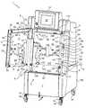
도 1은 백이 없는, 본 발명의 제1 실시예의 예에 따른 생물학적 액체 처리 설비를 위한 장치의 사시도이다.
도 2는 백을 갖는, 도 1과 유사한 도면이다.
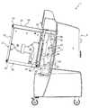
도 3은 우측 측부 패널이 부분적으로 절단 제거되어 있는, 장치의 우측 측부로부터의 도면이다.
도 4는 폐쇄 도어 위치에서, 장치의 좌측 측부로부터의 도면이다.
도 5는 장치의 베이스에 도어를 연결시키는 힌지 시스템을 도시하는 부분 단면도이다.
도 6은 제2 외피가 없는 격리 상태의 도어의 내부의 도면이며, 이 도어의 이 제2 외피의 로킹 시스템을 도시한다.
도 7 및 도 8은 각각 언로킹 및 로킹 상태에서 도어 내의 제2 외피의 로킹 시스템을 도시하는, 도 2의 VII-VII의 단면도이다.
도 9 및 도 10은 도 7 및 도 8 각각의 IX-IX 및 XX 각각 상에서의 단면도이다.
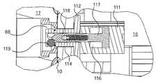
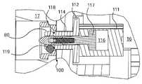
도 11은 제1 및 제2 외피를 함께 로킹하기 위한 시스템의 격리 사시도이다.
도 12 및 도 13은 로킹 시스템이 각각 언로킹 및 로킹 상태에 있는, 제1 및 제2 외피를 부분적으로 도시하는 단면도이다.
도 14는 후방 패널이 제거되어 있는, 제1 외피의 후방으로부터의 도면이다.
도 15는 후방 패널을 구비하는 도 14와 유사한 도면이다.
도 16은 제1 외피가 제거되어 있는, 장치의 전방으로부터의 부분도이다.
도 17 및 도 18은 각각 비연결 및 연결 상태에서 수형 및 암형 커넥터를 개략적으로 도시하는, 장치의 부분 단면도이다.
도 19는 설비의 생물학적 액체 처리 회로의 개략도이다.
도 20은 백의 사시도이다.BRIEF DESCRIPTION OF THE DRAWINGS The subject matter of the present invention will now be described, by way of example and not by way of limitation, with reference to the accompanying drawings in which:
1 is a perspective view of an apparatus for a biological liquid treatment facility according to an example of the first embodiment of the present invention without a bag.
Fig. 2 is a view similar to Fig. 1 with a bag.
3 is a view from the right side of the device, with the right side panel partially cut away.
4 is a view from the left side of the apparatus, in the closed door position;
5 is a partial cross-sectional view showing a hinge system for connecting a door to the base of the apparatus;
Figure 6 is a view of the interior of a door in an isolated state without a second shell, showing the locking system of this second shell of this door.
Figures 7 and 8 are cross-sectional views of VII-VII of Figure 2 showing the locking system of the second envelope in the door in the unlocking and locking states, respectively.
Figures 9 and 10 are cross-sectional views on IX-IX and XX respectively, of Figures 7 and 8, respectively.
11 is an exploded perspective view of the system for locking the first and second shells together.
Figures 12 and 13 are cross-sectional views partially illustrating first and second shells, respectively, in which the locking system is in the unlocking and locking states, respectively.
Fig. 14 is a rear view of the first envelope from which the rear panel is removed. Fig.
Figure 15 is a view similar to Figure 14 with a rear panel.
16 is a partial view from the front of the apparatus in which the first shell is removed;
17 and 18 are partial cross-sectional views of the device, schematically showing male and female connectors in the uncoupled and connected state, respectively.
19 is a schematic diagram of a biological liquid treatment circuit of a facility.
20 is a perspective view of the bag;
도 1 및 도 2는 생물학적 액체 처리 설비(미도시)를 위한 장치(1)를 예시한다.Figures 1 and 2 illustrate an
장치(1)는 일반적으로 평행육면체 형태로 이루어진다.The
이 장치(1)는 베이스(2)를 포함하고, 이 베이스(2)는 제1 측부 면(3), 제1 측부 면(3)에 대향한 면인 제2 측부 면(4), 제1 및 제2 측부 면(3, 4)과 만나는 전방 면(5) 및 전방 면(5)에 대향한 면이면서 제1 및 제2 측부 면(3, 4)과 만나는 후방 면(6)을 갖는다.The
장치(1)는 프레스(9)와 백(10)을 구비하는 회로(8)를 더 포함하고, 이는 액체를 위한 복수의 커넥터(11)와, 그 회로(13)를 도 2에서 볼 수 있는 이들 커넥터(11) 사이에서 액체를 전달하기 위한 네트워크(12)를 포함한다.The
프레스(9)는 강성 재료의 고체 블록으로부터 각각 형성된 두 개의 외피(16, 17)를 포함한다.The
여기서, 외피(16, 17)는 아세탈이라고도 지칭되는 폴리옥시메틸렌(POM)으로 이루어지며, 각각은 대체로 평행육면체 형태를 갖는다.Here, the
외피(16)는 베이스(2)의 전방 면(5) 상에 장착된다.The
장치(1)는 베이스(2)에 힌지결합된 도어(20)를 더 포함한다.The device (1) further comprises a door (20) hinged to the base (2).
외피(17)는 이 도어(20) 내에 장착된다.The
장치(1)는 도어(20)가 폐쇄되어 외피(16)를 덮고 있는 폐쇄 도어 위치와, 백(10)이 외피(16)에 의해서만 지지되는 다른 위치를 갖는다.The
이 다른 위치에서, 외피(17)는 외피(16)로부터 이격된다.In this other position, the
폐쇄 도어 위치에서, 백(10)은 두 개의 외피(16, 17) 사이에 삽입된다.In the closed door position, the
장치(1)는 저부에서 주머니(sachet)를 포함하는 하나 이상의 탱크(미도시)를 수용하기 위한 목적의 폐쇄된 베이(186)를 구비하며, 이 탱크는 예로서 처리된 액체를 수집하기 위한 용기 또는 폐기물 용기를 형성한다.The
이 베이(186)는 장치(1)의 전방 면(5) 상에 배치된 활주 패널(7)에 의해 폐쇄되며, 이 패널(7)은 그후 탱크를 삽입 및 인출하도록 장치(1)의 후방을 향해 하향 병진 이동되도록 구성된다(도 1의 화살표 참조).This
제어 패널(14)은 장치(1)의 전방 면(5)의 상단에 배열된다.The
이 제어 패널(14)은 생물학적 액체 처리 공정이 확인 및 제어될 수 있게 하는 그래픽 터치 인터페이스(15)를 구비한다.The
따라서, 이 제어 패널(14)은 사용자가 이를 사용할 수 있게 하는 높이에 배열된다.Thus, the
그 이동을 용이하게 하기 위해, 장치(1)는 네 개의 캐스터(18)(그 중 셋을 도 1에 볼 수 있음)에 장착된 카트의 형태이며, 두 개의 캐스터는 브레이크(19)를 포함하는 장치(5)의 전방 면 아래에 배치되고, 장치(1)는 또한 각각의 측부 면(3, 4)의 근방에서 전방 면(5)의 각각의 대향 측부 상에 두 개의 손잡이(21)를 구비한다.To facilitate its movement, the
장치(1)는 그 전방 면(5)에 새시(25)를 포함한다.The
특히, 도 3에서 볼 수 있는 바와 같이, 이 새시(25)는 경사져있다.Particularly, as can be seen from Fig. 3, this
새시(25)는 외부 주연부와 내부 주연부를 가지며, 이들은 네 개의 측부, 즉, 대향하는 측부들인 좌측 측부(140)(도 16에서 볼 수 있음) 및 우측 측부(141)와, 대향하는 측부들인 상단 측부(143) 및 저부 측부(142)(도 16에서 볼 수 있음)에 의해 경계지어진다.The
좌측 측부(140)와 우측 측부(141) 각각은 각각의 측부로부터 뻗어나와 상방으로 연장하는 두 개의 중첩된 L-형상 후킹 클로우(26)를 포함한다.The
지지 판(27)은 2개의 후킹 클로우(26)들 사이에서, 새시(25)의 우측 측부(141)에 체결된다.The
지지 판(27)은 우측 측부(141) 상에 더 높게 위치된 후킹 클로우(26) 아래에 바로 근접하게 배치되며, 그래서, 그 동일 우측 측부(141) 상에 하부가 하향한 상태로 배치된 후킹 클로우(26)에 대한 자유로운 접근로를 남긴다.The
지지 판(27)은 생물학적 액체의 처리를 위해 필요할 수 있는 기구를 그 위에 배치하도록 플랫폼(미도시)이 그 위에 체결되게 구성되는 두 개의 체결 헤드(28)를 포함한다.The
이들 기구는 예로서, pH 또는 전도성을 측정하는 센서 같은 선택적 키트일 수 있으며, 수행되는 처리의 유형에 따라 사용자에 의해 선택된다.These instruments may be, for example, pH or an optional kit, such as a sensor for measuring conductivity, and are selected by the user depending on the type of treatment being performed.
장치(1)의 베이스(2)는 도어(20)의 상보적 장치(40)에 의해 폐쇄 도어 위치에서 그 도어(20)의 위치설정 및 로킹을 가능하게 하는 장치(29)를 더 포함한다.The
장치(29) 중 셋은 특히, 도 1 및 도 2에서 볼 수 있는 바와 같이, 상단 우측, 저부 우측 및 저부 좌측에서 각각 새시(25)의 코너에 위치된다.The three of the
이들 장치(29) 각각은 본체, 환형 견부(미도시) 및 이 환형 견부에 연결된 헤드를 포함하고, 이 헤드는 원추형 튜브(도 1 및 도 2)의 형태를 가지며, 내부에 원추형 팁을 구비한 로드(30)를 구비한다. 본체는 공압 챔버 및 원추형 팁을 구비한 로드(30)에 기계적으로 연결되는 피스톤을 포함하고, 로드(30)는 헤드 내에서 연장하도록 구성된다.Each of these
도 1 내지 도 3에서 볼 수 있는 바와 같이, 도어(20)는 대체로 직사각형 윤곽을 갖는 프레임(35)을 포함한다.1 to 3, the
이 프레임(35)은 제1 측부(36), 제1 측부(36)에 대향 측부에 있는 제2 측부(37), 제1 및 제2 측부(36, 37)와 만나는 제3 측부(38) 및 제1 및 제2 측부(36, 37)와 만나면서 제3 측부(38)에 대향하는 제4 측부(39)를 갖는다.The
프레임(35)은 베이스(2)의 장치(29)와 협력하도록 구성된 세 개의 상보적 장치(40)를 포함하며, 이 상보적 장치(40)는 각각 도 1 내지 도 3에서 볼 수 있는 바와 같이 상부 좌측, 저부 좌측 및 저부 우측 코너에 위치된다.The
이들 상보적 장치(40)는 제1 원통형 부분(155)과 견부(157)(도 16)에 의해 제1 부분(155)에 연결되면서 중공인 제2 원통형 부분(156)을 구비한다. 이 제2 부분(156)은 제1 부분(155)의 직경보다 작은 직경으로 이루어진다. 또한, 제2 부분(156)은 그 외부 표면 상에 세 개의 개구(158)를 구비한다.These
이들 상보적 장치(40)는 세 개의 볼(미도시)을 더 포함하고, 이들 각각은 각각의 개구(158)를 통해 통과함으로써 제2 부분(156)으로부터 돌출할 수 있다.These
폐쇄 도어 위치에서, 도어(20)의 각각의 상보적 장치(40)의 제2 부분(156) 각각은 베이스(2)의 각각의 장치(29)의 각각의 헤드 내에 삽입된다.In the closed door position, each
장치(29) 및 상보적 장치(40)는 그 동작이 잘 알려져 있는 연장 위치와 수축 위치를 갖는, 스프링(미도시)을 구비한 이중 작동 유형의 공압 잭을 구비하는 볼-로크 핀 시스템을 쌍으로 형성한다.The
장치(29)의 로드(30)는 잭이 그 연장 위치에 있을 때 중공 제2 원통형 부분(156)에 도입되도록 구성된다.The
잭의 이러한 위치에서, 로드(30)는 볼들 각각이 개구(158)를 통과할 때까지 볼을 추진하고, 그래서, 베이스(2)에 대한 도어(20)의 이동을 차단한다.In this position of the jack the
장치(1)는 힌지 시스템을 더 포함하고, 이 힌지 시스템에 의해 도어(20)가 베이스(2)에 힌지결합된다.The
이 힌지 시스템은 도어(20)의 프레임(35)의 상단 우측 코너에 체결된 제1 힌지 부분(43)과, 장치(1)의 베이스(2)의 측부 면(3)에 체결된 제2 힌지 부분(44)을 포함하는 단일 힌지(42)를 구비한다.The hinge system includes a
이 힌지 부분(43)은 세 개의 체결 스크류(158)(도 6)를 통해 프레임(35)의 제1 측부(36)에 체결된다.The
도 5에서 더 상세히 볼 수 있는 바와 같이, 도어(20) 및 베이스(2) 각각의 힌지 부분(43, 44)은 피봇식 링크를 형성하는 로드(45)에 의해 함께 결합된다.As can be seen in more detail in FIG. 5, the
베이스(2)의 힌지 부분(44)이 베이스(2)의 측부 면(3)에 6개 체결 스크류(46)를 통해 체결된다.The
이 힌지 부분(44) 배후에 위치된 조절 쐐기(미도시)는 힌지 부분이 마찬가지로 조절될 수 있게 한다.The adjustment wedge (not shown) located behind the
또한, 도 5의 저부에서, 굴곡 판(41) 및 체결 스크류(185)를 통해 그 힌지 부분(44)에 간접적으로 손잡이(21)가 체결된다는 것을 볼 수 있다.It can also be seen that at the bottom of Fig. 5, the
힌지 부분(44)의 상부 부분 상에서, 기계적 스프링(48)이 도어(20)의 개방 및 폐쇄를 용이하게 하도록 플라스틱 정지부(160)를 갖도록 배열된다.On the upper portion of the
또한, 장치는 폐쇄 도어 위치 및 다른 위치를 검출함으로써 도어(20)의 개방 및 폐쇄를 위한 안전성을 확인 및 제공하기 위해 위치 센서(162)를 포함한다.The apparatus also includes a position sensor 162 for identifying and providing safety for opening and closing the
또한, 공압 시스템(49)은 도어(20) 내에 위치되어 있는, 외피(17)를 로킹하기 위한 시스템(후술됨)에 대한 공급을 위해 힌지 부분(44)의 상부 부분 상에 배열된다.The
이를 위해, 이 시스템(49)은 공압력 공급부(미도시) 및 로드(45) 내에 형성된 개구(51) 양자 모두에 연결된 커넥터(50)를 포함하며, 개구(51)는 커넥터(50)로부터 도어(20) 내에 있는 힌지 부분(43)으로 로드(45)에서 연장한다.To this end, the
폐쇄 도어 위치에서, 특히 도 4에 예시된 바와 같이, 도어(20)의 힌지 부분(43)이 그를 중심으로 피봇하는 회전축(X)이 외피(16, 17)들이 그들 사이에 백(10)을 클램핑할 때 외피(16, 17) 사이에 형성된 분할 표면(P)에 대해 오프셋된다.At the closed door position, the swivel axis X, in which the
분할 표면(P)에 대한 축(X)의 장치(1)의 전방을 향한 이러한 축방향 오프셋은 도어(20)의 외부 주연부에서 도어(20)와 베이스(2) 사이에 측방향 유극(53)이 형성될 수 있게 한다.This axial offset of the axis X relative to the dividing surface P toward the front of the
따라서, 예로서, 도 4에 예시된 백(10)의 커넥터(11)에 대한 접근이 크게 용이해진다.Thus, by way of example, access to the
도어(20)는 그 프레임(35)에서 외피(17)(도 6)를 로킹하기 위한 시스템(55)을 더 포함한다.The
이 시스템(55)은 그 상단 부분 상에 프레임(35)의 각각의 대향 측부 상에 배치된 두 개의 잭(56)과, 프레임(35)의 높이의 대부분에 걸쳐 연장하는 로드(57)를 포함한다.The
잭(56)은 스프링을 갖는 단일 작동 공압 유형으로 이루어지며, 이는 잭(56)내로 통합되지 않고, 도 5에서 볼 수 있는 커넥터(50)에 의해 공급받는다.The
이하에 더 상세히 볼 수 있는 바와 같이, 이들 잭(56)은 각각 로드(57)에 연결되고, 각각 시스템(55)의 로킹 위치와 언로킹 위치 사이에서 이 로드(57)를 추진하도록 구성된다.These
각 로드(57)는 두 개의 로킹 볼트(58)를 포함한다.Each
시스템(55)은 프레임(35)의 저부에 배치된 두 개의 스프링(59)을 포함하고, 각 스프링(59)은 그 각각의 로드(57)를 그 로킹 위치로 추진하도록 로드(57)에 연결되고, 따라서, 대응 로킹 볼트(58)를 전진시키도록 로드(57)에 연결된다.The
백(10)은 전달 네트워크(12)의 커넥터(11)와 폐쇄 윤곽을 형성하는 밀봉부에 의해 서로 연결된 두 개의 가요성 필름(65, 66)을 포함한다(도 2 및 도 20).The
따라서, 필름(65, 66) 각각은 본 출원인으로부터의 PureFlexTM이다.Thus, each of the
이는 네 개의 층, 내측으로부터 외측으로, 각각, 액체와 접촉하기 위한 재료를 형성하는 초 저밀도 폴리에틸렌(ULDPE)의 층, 가스에 대한 배리어를 형성하는 에틸렌과 비닐 알콜(EVOH)의 공중합체, 에틸렌 및 비닐 아세테이트(EVA)의 공중합체 층 및 외부 층을 형성하는 초 저밀도 폴리에틸렌(ULDPE)의 층을 포함하는 공압출 필름이다.It consists of four layers, a layer of ultra low density polyethylene (ULDPE), a layer of ultra low density polyethylene (ULDPE), a layer of ethylene and vinyl alcohol (EVOH) forming a barrier to gas, Is a coextruded film comprising a layer of ultra low density polyethylene (ULDPE) forming a copolymer layer and an outer layer of vinyl acetate (EVA).
이 밀봉부는 필름(65, 66)의 주연부에 형성된 용접 비드이다.This sealing portion is a weld bead formed on the periphery of the
필름(65, 66) 및 액체를 위한 커넥터(11)에 추가로, 백(10)은 도관(13)을 형성하기 위한 공압 보조제(미도시)를 위한 커넥터를 포함한다(도 20의 도 13a 내지 13f).In addition to the
백(10)의 폐쇄 윤곽은 그 내부로 도관(13)이 연장하는 액체 처리 구역(67)을 형성한다.The closed contour of the
폐쇄 윤곽은 제1 측부(68), 제1 측부(68)에 대향한 측부인 제2 측부(69), 제1 및 제2 측부(68, 69)와 만나는 제3 측부(70) 및 제3 측부(70)에 대향한 측부이면서 제1 및 제2 측부(68, 69)와 만나는 제4 측부(71)를 갖는다. 전달 네트워크(12)의 커넥터(11)는 특히 도 20에서 볼 수 있는 바와 같이, 제1, 제2 및 제3 측부(68, 69, 70) 내부 및 외부로부터 뻗어나온다.The closed contour includes a
백(10)의 치수는 외피(16, 17)의 표면들의 치수에 대응한다.The dimensions of the
후술될 바와 같이, 백(10)은 외피(16, 17)에 의한 그 사이에서의 클램핑을 위해 백(10)의 면 중 하나가 외피(16)의 면과 접촉하고, 백(10)의 다른 면이 외피(17)의 면과 접촉한다.As will be described later, the
그 제4 측부(71)에서, 백(10)은 위치설정을 위한 세 개의 관통 개구(73)를 더 포함한다.In its
이들 위치설정 개구(73)는 정렬되고 규칙적으로 이격되어 있으며, 개구들(73) 중 두 개는 백(10)의 제4 측부(71)의 각각의 대향 측부 상에 위치되고, 다른 개구(73)는 백(10)의 제4 측부(71)의 중심에 배치된다.These positioning
이들 위치설정 개구(73)는 후술될 바와 같이 외피(16)의 백(10)의 위치설정을 위해 기능한다.These positioning
백(10)은 그 처리 구역(67)에서 외피(16, 17)를 함께 로킹하기 위한 두 개의 관통 개구(75)를 포함하고, 이들 로킹 개구(75)는 위치설정 개구(73)보다 큰 직경을 갖는다.The
이들 로킹 개구(75)는 대부분의 도관(13)이 존재하는 위치에서 처리 구역(67) 내에 배치되며, 그 이유는 이것이 압력의 힘이 처리 동안 가장 커지는 위치들에 있기 때문이다. 따라서, 로킹 개구(75)는 도관(13)에 의해 적어도 부분적으로 둘러싸여진다.These locking
이하에서, 외피(16, 17)를 함께 로킹하기 위한 수단이 이 로킹을 수행하는 방식 및 동시에, 회로(8) 내의 백(10)을 그들 사이에 클램핑하는 방식을 설명한다.In the following, the manner in which the means for locking the
백(10)은 다른 위치설정 개구(77)를 더 포함한다.The
위치설정 개구(77) 중 하나가 백(10)의 상단 좌측에 위치된 위치설정 개구(73)의 근방에서 백(10)의 제4 측부(71)에 배치되며, 다른 위치설정 개구(77)는 처리 구역(67)에서 대향 말단에, 말하자면, 백(10)의 저부를 향해 배치된다.One of the
이들 위치설정 개구(77)는 후술될 바와 같이 장치의 폐쇄 도어 위치에서 도어(20)를 위치설정하도록 기능한다.These positioning
도 1 내지 도 3에서 볼 수 있는 바와 같이, 외피(17)는 여기서 평탄한 기준 표면(80)을 가지며, 이 기준 표면(80) 내로 만입된 복수의 성형 채널(81)을 갖는다. 이 외피(17)는 제1 측부(82)와, 제1 측부(82)에 대향 측부인 제2 측부(83)와, 제3 측부(84)와, 제3 측부(84)에 대향 측부인 제4 측부(85)를 가지며, 이들 제3 및 제4 측부(84, 85) 각각은 제1 및 제2 측부(82, 83)와 만난다.As can be seen in Figures 1-3, the
그 제4 측부(85) 상에서, 외피(17)는 백(10)을 위치설정하기 위한 제3 위치설정 구멍(86)을 구비하며, 이들은 후술된 바와 같이, 백(10)이 외피(16, 17) 사이에 클램핑되어 있는 폐쇄 도어 위치에서 백(10)의 위치설정 개구(73)에 대면하여 배열된다.On its
또한, 외피(17)는 폐쇄 도어 위치에서 도어(20)를 위치설정하기 위한 두 개의 다른 위치설정 구멍(87)을 구비하며, 그 중 하나는 외피(17)의 제1 측부(82)에 위치되고, 나머지는 다른 말단에서 외피(17)의 저부를 향해 배치된다.The
후술될 바와 같이, 이들 두 개의 위치설정 구멍(87)은 백(10)이 외피(16, 17) 사이에 클램핑되어 있는 폐쇄 도어 위치에서 백(10)의 위치설정 개구(77)에 대면하도록 배열된다.These two
중앙 구역에서, 외피(17)는 이 외피(17)의 위치설정 구멍(86, 87)보다 큰 직경의 두 개의 다른 로킹 구멍(88)을 더 포함하며, 로킹 구멍(88)은 후술된 바와 같이, 외피(16, 17)를 함께 로킹하도록 기능한다.In the central region the
이들 로킹 구멍(88)은 도관(13)의 형성을 위해 기능하는 대부분의 채널(81)이 존재하는 위치에 배치되어 있고, 그 이유는 이것이 처리 동안 압력의 힘이 가장 큰 위치들에 있기 때문이다. 따라서, 로킹 구멍(88)은 채널(81)에 의해 적어도 부분적으로 둘러싸여진다.These locking holes 88 are located at the locations where most of the
후술된 바와 같이, 이들 로킹 구멍(88)은 백(10)이 외피(16, 17) 사이에 클램핑되어 있는 폐쇄 도어 위치에서 백(10)의 로킹 개구(75)에 대면하도록 배열된다.These locking holes 88 are arranged to face the locking
도 7 및 도 10에 도시된 바와 같이, 외피(17)는 외피(17)의 본체의 오목부에 각각 형성된 네 개의 로크 스트라이크(89)를 구비한다.7 and 10, the
두 개의 로크 스트라이크(89)는 외피(17)의 제1 측부(82)를 따라 배열되고, 두 개의 다른 로크 스트라이크(89)는 외피(17)의 제2 측부(83)를 따라 배열되고, 말하자면, 네 개의 로크 스트라이크(89)는 대향 쌍이다.Two lock strikes 89 are arranged along the
전술한 바와 같이, 외피(17)는 도어(20)의 프레임(35) 내에 체결되며, 도어(20) 내로의 그 외피(17)의 로킹은 도 7 내지 도 10을 참조로 설명된다.The
각 잭(56)은 공압 챔버(91)와 로드에 의해 연장되는 가동성 피스톤(92)을 포함하는 본체(90)를 구비하며, 잭은 도어(20)의 프레임(35) 내에 수용되고, 각 피스톤(92)은 연장 위치와, 피스톤(92)이 그 연장 위치에 대해 사전결정된 여정을 통해 이동되어 있는 수축 위치를 가진다.Each
각 잭(56)은 힌지 부분(43, 44)을 연결하는 로드(45) 내에 형성된 개구(51)에 공압식으로 연결된다.Each
잭(56)은 도 7에서 연장 위치에 예시되어 있고, 도 8에서 수축 위치에 예시되어 있다.The
각 피스톤 로드(92)는 로드(57)에 체결되고, 로드(57)는 또한 스프링(59)에 체결된다.Each
공압 챔버(91)는 압력하에 있을 때 스프링(59)에 대해 피스톤(92)을 편의시킨다. 피스톤(92)이 여정의 단부에 있을 때, 스프링(59)은 수축 위치(도 7 및 도 9)에 있고, 피스톤(92)은 연장 위치에 있다.The
따라서, 로드(57)는 하향 병진 이동되고, 외피(17)는 도어(20)의 프레임(35)의 측부(36, 37)에 대해 삽입된 상태이며, 그 기준 표면(80)은 외향 전향되고, 각 로드(57)의 로킹 볼트(58)는 외피(17)의 대응 오목부 내로 삽입된다.Thus, the
각 잭(56)의 공압 챔버(91)가 대기압에 있을 때, 스프링(59)은 로드(57)를 통해 피스톤(92)을 그 피스톤(92)의 여정 위치의 다른 단부를 향해 압박한다. 그 위치가 도달되었을 때, 스프링(59)은 연장 위치에 있고, 피스톤은 수축 위치에 있다.When the
따라서, 로드(57)는 상향 병진 이동되고, 그 로킹 볼트(58) 각각은 도어(20)에 그 외피(17)를 로킹하기 위해 외피(17)의 로크 스트라이크(89) 내로 각각 진입되어 있다.The
외피(16)는 각각 대응 성형 채널(81)에 대면하는, 기준 표면(95)에 대해 만입된 성형 채널(96) 및 평탄한 기준 표면(95)을 갖는다.The
일반적으로, 표면(80, 95)은 유사한 치수를 가지며, 성형 채널(96)의 배열은 성형 채널(81)의 세트의 경면 대칭 이미지이다.Generally, surfaces 80 and 95 have similar dimensions, and the arrangement of
성형 채널(81, 96)은 반 타원 단면으로 이루어진다.The forming
표면(80, 95)은 각각 대체로 관형인 공동의 네트워크를 형성하도록 채널(81, 96)이 서로 정합하는 상태로 서로에 대해 적용될 수 있다.The
외피(16)는 제1 측부(145)와, 제1 측부(145)에 대해 대향 측부인 제2 측부(146)와, 제3 측부(147)와, 제3 측부(147)에 대해 대향 측부인 제4 측부(148)를 가지며, 제3 및 제4 측부(147, 148)는 각각 제1 및 제2 측부(145, 146)와 만난다.The
또한, 외피(16)는, 외피(16)가 새시(25)에 대치되어 있을 때 이 새시(25) 상에 배치된 후킹 클로(26) 내에서 상단으로부터 저부로의 수직 병진 이동에 의해 결합되도록 구성된 다우엘(100)을 대향 측부 벽(98, 99) 상에 구비한다.The
또한, 이들 동일한 대향 측부 벽(98, 99) 상에서, 외피(16)는 외피(16)를 조작하기 위한 로드(101)를 가지며, 로드(101)는 다우엘(100)보다 길다.Also on these same
이 조작은 장치(1)의 사용자에 의해 또는 예로서 전기적일 수 있는 윈치(winch)의 도움으로 수행된다.This operation is carried out by the user of the
외피(16)의 중량 및 경사의 도움으로, 그리고, 후킹 클로(26) 내의 다우엘(100)의 결합의 도움으로, 외피(16)는 새시(25)에 견고히 체결된다.With the help of the weight and inclination of the
그 평탄한 기준 표면(95) 상에서, 또한, 외피(16)는 그 경사가 장치(1)의 내부로 지향되는, 경사 표면(103)에 의해 하향 연장되는 오목한 부분(102)을 갖는다.On its
이 경사 표면(103)은 용기를 포함하는 베이(6)에 대한 접근로의 제공을 가능하게 한다.This
특히 외피(16)의 제3 측부(147)의 위치에 배치되고, 회로(8)의 커넥터(11)에 연결된 파이프(미도시)는 또한 용기에 연결될 수 있다.A pipe (not shown) connected to the
하부 면(97) 상에서, 외피(16)는 경사 표면(103) 상에서 뻗어나오는 반전된 거터 형상의 채널(104)을 더 포함한다(도 1 및 도 14).On the
이 채널(104)은 기준 표면(95)이 내향 전향되도록 베이스(2)의 새시(25) 상의 외피(16)의 설치시 실수 방지 장치(fool proof device)로서 기능한다.This
외피(16)는 그 제4 측부(148)의 위치에서 세 개의 후킹 스터드(106)를 포함하며, 그 중 둘은 외피(16)의 각각의 대향 측부 상에 배치되고, 세 번째는 실질적으로 외피(16)의 제4 측부(148)의 중심에 배치되며, 이들 세 개의 스터드(106)는 서로 균등하게 이격 배치된다.The
도 2에서 볼 수 있는 바와 같이, 이들 스터드(106)는 외피(16) 상에 백의 현수를 위해 백(10)의 위치설정 개구(73)를 통과하도록 구성된다.As can be seen in Figure 2, these
또한, 이들 동일한 후킹 스터드(106)의 말단 단부는 폐쇄 도어 위치에서 외피(17)의 위치설정 구멍(86) 내로 삽입되도록 구성된다.Also, the distal ends of these
외피(16)는 도어(20)의 위치설정을 위해 두 개의 위치설정 다우엘(107)을 포함하며, 그 중 하나는 그 외피(16)의 상단 좌측에 위치된 후킹 스터드(106)에 근접하게 외피(16)의 제4 측부(148) 상에 위치되며, 다른 위치설정 다우엘(107)은 다른 말단에, 말하자면, 제3 측부(147)의 위치에서 두 개의 성형 채널(96) 사이에 외피(16)의 저부에 배치된다.The
이들 위치설정 다우엘(107)은 백(10)의 개구(77)를 통과하도록 구성되며, 이들 위치설정 다우엘(107)의 말단 단부는 외피(17)의 위치설정 구멍(87) 내로 삽입되도록 구성된다.These positioning dowels 107 are configured to pass through the
외피(16)는 도관(13)의 형성을 위해 기능하는 대부분의 채널(96)이 존재하는 위치에 위치되는 두 개의 로킹 구멍(108)을 포함하며, 그 이유는 이것이 처리 동안 압력의 힘이 가장 큰 이들 위치들에 있기 때문이다. 로킹 구멍(108)은 따라서 적어도 부분적으로 채널(96)에 의해 둘러싸여진다.The
이들 로킹 구멍(108)은 외피(16) 상에 배치될 때 백(10)의 로킹 관통 개구(75)에 대면하도록 배열되며, 또한, 폐쇄 도어 위치에서 외피(17)의 대응 로킹 구멍(88)에 대면하도록 배열된다.These locking
외피(16)의 로킹 구멍(108)은 도어(20)가 폐쇄 위치에 있을 때 외피(16, 17)를 함께 로킹하기 위해, 그리고, 회로(8) 내에 백(10)을 클램핑하기 위해 상세한 내용이 후술되어 있는 볼-로크 핀(110)에 의해 통과된다.The locking
특히, 도 11 내지 도 13에서 볼 수 있는 바와 같이, 각 볼-로크 핀(110)은 본체(111)와, 횡단 면(113)을 구비하면서 헤드(114)에 연결되는 환형 견부(112)를 포함한다.11-13, each ball-
네 개의 로드(115)가 본체(111)를 외피(16)에 체결하기 위해 횡단 면(113)으로부터 돌출하여 외피(16)의 본체 내에 형성된 개구(미도시) 내로 삽입된다.Four
본체(111)는 공압 챔버(116)와 피스톤(117)을 포함하며, 피스톤(117)은 원추형 팁을 갖는 로드(118)에 기계적으로 연결된다.The
이 로드(118)는 핀(110)의 헤드(114) 내에서 연장한다.The
세 개의 볼(119)은 이 헤드(114) 내에 형성된 개구를 통과함으로써 헤드(114)로부터 돌출할 수 있도록 배열된다.Three
핀(110)은 이중 작동형 잭과 유사하고, 이 핀(110)은 두 개의 공압 커넥터(120)를 포함한다.The
각 핀(110)의 헤드(114)는 외피(16)의 대응 로킹 구멍(108)을 통과하고, 헤드(114)는 또한 백의 대응 로킹 개구(75)를 통과하고, 헤드(114)는 최종적으로 폐쇄 도어 위치에서 외피(17)의 대응 로킹 구멍(88) 내로 뻗어나온다.The
핀(110)의 커넥터(120) 중 하나가 피스톤(117) 상에 작용하도록 공압 챔버(116)의 제1 부분이 가압될 수 있게 한다. 피스톤(117)이 여정의 종점에 있을 때, 볼(119)은 연장 위치에 있고, 말하자면, 이들은 외피(17)의 로킹 구멍(88) 내로 연장하도록 헤드(114)로부터 돌출한다(도 13).Allows the first portion of the
로킹 구멍(88)은 볼(119)이 연장될 때, 외피(16, 17)가 견고히 로킹되도록 구성된다.The locking
이를 위해, 로킹 구멍(88)은 백이 외피(16, 17) 사이에 클램핑될 때 백(10)에 대면하도록 구성되는 제1 직경을 갖는 제1 부분과, 그후, 오목부와, 그리고, 최종적으로 제1 직경보다 큰 제2 직경을 갖는 제2 부분을 포함한다.To this end, the locking
따라서, 핀(110)의 연장 위치에서, 각 핀(110)의 볼(119)이 대응 로킹 구멍(88)의 제2 부분 내로 돌출하며, 이 로킹 구멍(88)의 제1 부분은 볼(119)을 차단시킴으로써 핀의 분리를 방지한다.Thus, in the extended position of the
다른 커넥터(120)는 공압 챔버(116)의 제2 부분이 가압될 수 있게 하며, 이 제2 부분은 여정 위치의 다른 단부를 향해 피스톤(117)을 압박하도록 제1 부분에 대향된다. 이 위치가 도달될 때, 볼(119)은 수축 위치에 있고, 말하자면, 이들은 헤드(114) 내로 다시 진행한다(도 12).Another
외피(16, 17)에 추가로, 회로(8)는 도 14에 예시된 바와 같이, 여기서 외피(16)의 후방에 설치되는, 생물학적 액체의 처리를 위해 필요한 기구를 포함한다.In addition to the
예로서, 이 도관(13) 내의 액체의 통과를 방지 또는 허용하도록 도관(13)을 핀칭하기 위한 작동기와, 물리-화학적 값, 예로서, 압력의 센서(126)를 포함하는 핀치 밸브(125)가 예시되어 있다.An actuator for pinning the
또한, 공압 분배기(128)와 그 액체의 다양한 처리를 수행하기 위해 확인 및 제어를 위한 수단이 예시되어 있으며, 이 수단은 예로서, 확인 및 명령 유닛(127)에 의해 형성된다.In addition, means for identifying and controlling the
도 14에 예시된 예에서, 밸브(125)의 작동기 각각은 예로서, 밸브(125)가 개방 위치에 있을 때의 수축 위치와 밸브(125)가 폐쇄 위치에 있을 때의 연장 위치(미도시)를 갖는 가동성 핀칭 핑거와, 외피(16)에 체결된 본체를 포함한다.14, each of the actuators of the
연장 위치에서, 가동성 핑거는 채널(96) 중 하나 내로 돌출한다(미도시).In the extended position, the movable finger projects into one of the channels 96 (not shown).
각 센서(126)는 채널(96)과 정합하는 외피(16)에 체결되며, 센서(126)의 말단 단부는 이 채널(96) 내로 뻗어나오며, 실제로 유체와 접촉하지 않는다(미도시).Each
이런 센서는 잘 알려져 있고, 예로서, 백(10)의 외부 표면을 통해 압력을 측정하는 압력 센서를 포함한다.Such sensors are well known and include, for example, a pressure sensor that measures pressure through the outer surface of
외피(16)는 여기서는 이 외피(16) 배후에 설치되어 있는, 밸브(125)에 파워를 공급할 수 있게 하는 암형 커넥터(130)와, 센서(126)와, 분배기(128)와, 이 외피(16) 내로 통합되어 있는 확인 및 제어 유닛(127)을 더 포함한다.The
따라서, 공급부는 전기식(동력공급 및 제어를 위해) 및 공압식이다.Thus, the supply is electric (for power supply and control) and pneumatic.
이 암형 커넥터(130)는 외피(16)(배후로부터 볼 때)의 저부 우측에 위치된다.The
도 15에 예시된 바와 같이, 외피(16)의 후방 부분이 후방 패널(132)에 의해 덮여질 때, 암형 커넥터(130)에 대한 접근만이 가능하다.As illustrated in Figure 15, when the rear portion of the
장치(1)의 베이스(2)에 배열된 수형 커넥터(135)는 회로(8)의 암형 커넥터(130)에 연결될 수 있다.The
도 16 및 도 17에 예시된 바와 같이, 수형 커넥터(135)는 그 단부에서 수형 커넥터(135)를 지지하는 공압 잭(136)의 작동에 의해 이동가능하며, 이 수형 커넥터(135)는 암형 커넥터(130)에 대한 그 연결을 위해 새시(25)의 제3 측부(142)에 형성된 개구(138)를 통과하도록 구성된다(도 18).16 and 17, the
이제, 회로(8)의 조립에 대한 설명이 이루어진다.Now, a description of the assembly of the
외피(16)는 후킹 클로(26) 내에 위치되는 다우엘(100)에 의해 베이스(2)의 새시(25)에 체결된다.The
수형 및 암형 커넥터(135, 130)는 공압 잭(136)에 의해 함께 연결되며, 공압 잭은 회로(8)의 전기 및 공압 공급을 위해 이 수형 커넥터(135)가 이동가능하게 한다.The male and
백(10)은 다음에 외피(16) 상에 현수됨으로써 이 백(10)의 위치설정 개구(73)에 의해 체결되며, 이 위치설정 개구들에 외피(16)의 후킹 스터드(106)가 통과한다.The
외피(17)가 외피(16)로부터 이격되는 장치의 다른 위치에서, 외피(17)는 도어(20)의 프레임(35) 상에 조립되며, 그후, 도어(20)의 로드(57)의 시스템(55)에 의해 로킹된다.The
도어(20)는 다음에 외피(16, 17) 사이에 백(10)을 클램핑하도록 폐쇄된다. 따라서, 장치는 폐쇄 도어 위치에 있다.The
도어(20)가 폐쇄될 때, 그 위치설정은 특히 외피(16)의 다우엘(107)에 의해, 백(10)의 위치설정 개구(77)에 의해, 그리고, 외피(17)의 위치설정 구멍(87)에 의해 제공된다.When the
도어(20)는 새시(35) 및 도어(20) 각각의 장치(29, 40)를 통해 베이스(2)의 전방 면(5) 상에 로킹된다.The
외피(16, 17)는 또한, 백(10)이 외피(16, 17) 사이에 클램핑되게 하는 볼-로크 핀(110)을 통해 다음에 로킹된다.The
그후, 백(10)의 커넥터(11)에 대한 주변 처리 구성요소(미도시)의 연결이 파이프, 특히, 가요성 파이프를 통해 수행된다(백(10)의 장착 이전에 이미 수행되어 있지 않다면).The connection of the peripheral processing component (not shown) to the
이들 주변 처리 구성요소는 특히 예로서 다이아프램 유형의 하나 이상의 펌프에 의해 및/또는 처리를 위해 생성물을 수용하는 소스 용기에 의해 및/또는 처리된 액체 수집 용기에 의해 및/또는 크로마토그래피 컬럼에 의해 형성된다.These peripheral processing components can be used in particular by means of one or more pumps of the diaphragm type and / or by means of a source container which receives the product for treatment and / or by a liquid collection vessel which has been treated and / or by means of a chromatography column .
이들 주변 처리 구성요소는 하나 이상의 다른 장치 상에 배치, 예로서, 장치(1)에 병치된다.These peripheral processing components are located on one or more other devices, for example, juxtaposed to the
이들 다른 장치는 유리하게는 카트 같은 장치(1)이다.These other devices are
이들 연결은 백(10) 둘레에 형성된 측방향 유극에 의해 크게 용이해진다.These connections are greatly facilitated by the lateral clearance formed around the
물론, 이들 연결은, 후속하여, 말하자면, 외피(16) 상에 이 백(10)을 현수하는 시기에, 힌지 시스템에 의해 방해받지 않고, 외피(16) 상으로의 현수됨에 의해 백(10)을 체결하기 이전에 형성될 수 있다.Of course, these connections may also be achieved by suspending the
그후, 백(10)은 팽창된다: 액체를 위한 커넥터(11)는 막혀지고, 공압 보조제가 이 목적을 위해 제공된 커넥터(미도시)에 의해 주입된다.The
백(10)의 팽창의 효과는 필름들(65, 66)이 표면(95)과 채널(96)을 제공하는 외피(16)의 면과, 표면(80)과 채널(81)을 제공하는 외피(17)의 면에 각각 합치된다는 것이다.The effect of the expansion of the
타원 단면의 도관(13)은 채널(81, 96)의 위치에 형성된다.A
따라서, 프레스(9)와 백(10)은 사용중에 배치될 준비가 된 생물학적 액체를 처리하기 위해 회로(8)를 형성한다.Thus, the
생물학적 액체가 오염으로부터 보호되어야하는 백(10) 및 프레스(9)에 의해 형성되는 회로에서 처리되기 때문에, 백(10)은 액체를 위한 커넥터(11) 각각 상에, 그리고, 공압 보조제를 위한 커넥터(미도시) 상에 적소에 폐쇄 플러그를 구비하며, 이는 예로서, 감마 조사에 의해 살균된다. 백(11) 내부로 주입된 공압 보조제는 정화된다.Since the biological liquid is processed in the circuit formed by the
예로서, 공압 보조제는 팽창 커넥터(미도시)에 연결된 Millipore 사로부터 입수할 수 있는 AERVENT® 같은 소수성 필터에 의해 정화된 압축 공기이다.By way of example, the pneumatic adjuvant is compressed air purified by a hydrophobic filter, such as AERVENT (R), available from Millipore, which is connected to an expansion connector (not shown).
도 19는 프레스(9)와 백(10)에 의해 제공되는 회로(8)를 개략적으로 도시한다. 이 회로에서, 밸브(125A 내지 125G)는 작동기에 의해, 그리고, 핑거에 의해 핀칭될 때 도관(13)이 그에 대해 가압되게 되는 외피(17)의 부분에 의해 각각 형성된다.19 schematically shows a
커넥터(11B)는 도관(13E)에 의해, 커넥터(11C)에 연결된 공급 용기에 의해, 그 입구 측부가 공급 용기의 다른 커넥터에 연결되고 그 전달 측부가 커넥터(11A)에 연결되는 공급 펌프에 의해, 도관(13A)에 의해, 그리고, 필터에 의해 형성된 루프 내로 처리 대상 유체가 주입되도록 기능한다.The
커넥터(11B)에 의한 처리 대상 액체의 주입시, 밸브(125E, 125A)를 위한 것을 제외하고 모든 밸브가 개방된다. When the liquid to be treated is injected by the
처리 대상 생성물이 공급 용기 내로 전달되고 나서, 밸브(125F, 125C)가 폐쇄되는 반면, 다른 밸브는 개방되고, 공급 펌프는 동작되게 되며, 그래서, 처리 대상 액체가 상술한 루프 내로 유동한다.After the product to be treated has been transferred into the supply container, the
필터 내로의 통과시, 처리 대상 생성물은 도관(13D) 내로 통과하는 여과물 및 도관(13E) 내로 통과하는 리텐테이트(retentate)에 의해 정화되며, 그후 드레인으로 배출된다.Upon passage into the filter, the product to be treated is clarified by the filtrate passing into the
액체가 루프 내에서 충분히 순환되고, 정화 및 농축의 필요한 특성을 획득할 때, 폐쇄 위치로 밸브(125B)를 통과하고, 개방 위치로 밸브(125C)를 통과함으로써 커넥터(11E)에 연결된 수집 용기로 그 배출이 수행되고, 따라서, 처리된 액체는 액체가 최종 여과를 받게 되는 필터(151)를 통과함으로써 커넥터(11E)에 도달한다.When the liquid is sufficiently circulated in the loop and acquires the necessary properties of purge and concentration, it passes through the
상술한 작업에 추가로, 회로는 도관(13A 내지 13F) 및 밸브(125A 내지 125G)에 의해 형성된 전달 네트워크(12)에 의해 다양한 다른 동작을 이행할 수 있다.In addition to the work described above, the circuit can perform a variety of other operations by the
센서(126A 내지 126B)는 여기서 모든 압력 센서이다. 이들은 특히, 임의의 잉여 압력의 발생을 검출하고(센서(126A)) 및 필터의 적절한 동작을 보증하기 위해(센서(126B 내지 126D)) 적절한 팽창 작업이 확인될 수 있게 한다.The
예시되지 않은 변형에서, 힌지 시스템은 코너 내에 배치된 단일 힌지 이외의 수평 힌지 축을 갖는 도어를 포함한다. 수평 힌지 축을 갖는 이러한 도어는 장치의 베이스의 전방 면의 상단 및 저부에 체결된다. 단일 힌지 처럼, 수평 힌지 축을 갖는 이러한 도어는 백의 윤곽의 대부분에 걸쳐 측부 유극이 생성될 수 있게 한다.In a variation not illustrated, the hinge system includes a door having a horizontal hinge axis other than a single hinge disposed in a corner. These doors with horizontal hinge shafts are fastened to the top and bottom of the front face of the base of the device. Like a single hinge, such a door with a horizontal hinge axis allows side clearance to be created over most of the contour of the bag.
예시되지 않은 변형에서, 도어는 제거가능하며, 말하자면, 이는 베이스로부터 독립적이고, 이는 그에 대한 그 체결을 위해 베이스 상에 장착된다.In a variation not illustrated, the door is removable, that is to say, it is independent from the base, which is mounted on the base for its fastening thereto.
예시되지 않은 변형에서, 로드 시스템의 잭은 이중 작동 유형으로 이루어지거나, 공압식이 아닌 전기식 또는 유압식으로 이루어진다.In a variation not illustrated, the jacks of the load system may be of the dual operation type or of a non-pneumatic, electric or hydraulic type.
예시되지 않은 변형에서, 볼-로크 핀은 단일 작동 유형으로 이루어지고, 공압식이 아닌 전기식 또는 유압식으로 이루어진다.In an unillustrated variation, the ball-lock pin is of a single operating type and is of either electrical or hydraulic type rather than pneumatic.
예시되지 않은 다른 변형에서, 로드 시스템, 볼-로크 핀 및 후킹 클로우 대신 다른 메커니즘이 사용될 수 있다.In other variations not illustrated, other mechanisms may be used in place of the load system, ball-lock pins, and hooking crows.
예시되지 않은 변형에서, 백의 팽창은 백의 클램핑 이전에 또는 부분적으로 백의 클램핑 이전 및 부분적으로 백의 클램핑 이후에 수행된다.In an unillustrated variation, expansion of the bag is performed before clamping of the bag or partially before clamping of the bag and after clamping of the bag in part.
또 다른 예시되지 않은 변형에서, 어떠한 백의 이런 사전 팽창도 존재하지 않으며, 그 이유는 백의 도관이 처리 시점에서 백 내로의 유체의 전달에 의해 직접적으로 형성되기 때문이다.In another unexampled variant, there is no such pre-expansion of any bag, since the bag's conduit is directly formed by the transfer of fluid into the bag at the time of treatment.
예시되지 않은 변형에서, 동일 외피 위에 분산되는 대신, 물리-화학적 값의 센서 또는 센서들은 다른 외피 상에 배치되며 및/또는 어떠한 센서도 제공되지 않는다. 이 기구는 물론 생물학적 액체 상에 수행되는 처리에 따라 서로 다르다.In an unillustrated variation, instead of being dispersed over the same envelope, physico-chemical sensors or sensors are placed on different envelopes and / or no sensors are provided. This mechanism is of course different depending on the treatment performed on the biological liquid.
예시되지 않은 변형에서, 백은 직사각형이 아닌 삼각형 또는 원형이며, 이 경우에, 외피는 백, 그리고, 필요시, 도어 및 베이스의 형상에 적응된다. 예로서, 삼각형 백의 경우에, 도어는 단지 세 개의 측부를 가지며, 힌지 시스템은 적어도 나머지 두 개의 측부의 위치에서 측부 유극을 형성하도록 구성된다.In an unillustrated variation, the bag is triangular or circular rather than rectangular, in which case the envelope is adapted to the shape of the bag and, if necessary, of the door and the base. By way of example, in the case of a triangular back, the door has only three sides, and the hinge system is configured to form side clearances at least at the positions of the remaining two sides.
예시되지 않은 다른 변형에서,In another variation not illustrated,
- 단일 부재로 이루어지는 대신, 외피는 회로의 다양한 부분을 한정하도록 서로 연계되는 모듈식 부재의 세트에 의해 형성되며, 이 부재는 이들이 서로에 대해 정확하게 배치되는 것을 보증하도록 마크 또는 라벨을 구비한다. 마크 및 라벨은 예로서 참조 번호 또는 코드를 포함하며, RFID 유형으로 이루어질 수 있으며,Instead of being made of a single member, the shell is formed by a set of modular members which are interconnected to define the various parts of the circuit, which have a mark or label to ensure that they are correctly positioned with respect to each other. Marks and labels include, by way of example, reference numerals or codes, and may be of RFID type,
- 외피는 폴리옥시메틸렌 이외의 재료, 예로서, 스테인레스 스틸 또는 알루미늄 또는 특히 높은 밀도를 갖는 다른 플라스틱 재료 또는 세라믹이나 목재로 이루어지며,The envelope is made of a material other than polyoxymethylene, for example stainless steel or aluminum or other plastic material with a particularly high density, or ceramic or wood,
- 외피(16)는 두 개의 후킹 스터드(106) 또는 셋 초과의, 그리고, 이 경우에, 백(10)은 각각 단지 둘 또는 셋보다 많은 위치설정 개구(73)를 포함하며, 외피(17)를 위해 단지 두 개 또는 셋보다 많은 위치설정 구멍(86)을 포함하며, 이들 스터드, 개구 및 구멍은 균등하게 이격되거나 그렇지 않으며,The
- 외피(16)는 두 개보다 많은 위치설정 다우엘(107)을 포함하고, 그리고, 이 경우에, 백(10)은 두 개보다 많은 위치설정 개구(77)를 포함하며, 외피(17)는 두 개보다 많은 위치설정 구멍(87)을 포함하고, 이들 스터드, 개구 및 구멍은 균등하게 이격되거나 그렇지 않고,The
- 외피(16)는 두 개보다 많은 로킹 구멍(108)을 포함하고, 그리고, 이 경우에, 백(10)은 두 개보다 많은 로킹 개구(75)를 포함하며, 외피(17)는 두 개보다 많은 로킹 구멍(88)을 포함하며,The
- 백의 필름은 PureFlexTM 이외의 재료로, 예로서, Hyclone industries 사로부터 입수할 수 있는 필름 HyQ® CX5-14 같은 생물학적 액체와 호환성있는 다수의 층을 구비한 다른 필름 또는 Lonza 사로부터 입수할 수 있는 필름 Platinum UltraPac로 이루어지고,- The backing film may be a material other than PureFlexTM , for example, a film available from Hyclone Industries, Inc., or other film having multiple layers compatible with biological fluids such as HyQ® CX5-14, Film Platinum UltraPac,
- 센서(126)에 의해 측정되는 물리-화학적 값은 압력에 조합하여 또는 압력에 대안적으로 온도 및/또는 pH 및/또는 전도성이고,The physical-chemical value measured by the
- 성형 채널은 반 타원 단면 이외의 원형 단면으로 이루어지고,- the forming channel consists of a circular cross section other than half elliptical cross section,
- 다른 장치의 펌프 또는 펌프들은 다이아프램 유형 이외의 연동 유형으로 이루어지고,- pumps or pumps of other devices are of interlock type other than diaphragm type,
- 장치는 카트의 형태가 아니지만, 예로서 다른 지지대, 예로서, 테이블 상에 배치되고, 및/또는- the device is not in the form of a cart, but is, for example, placed on another support, for example on a table, and /
- 모든 주변 처리 구성요소가 동일 카트 상의 장치 또는 카트와는 다른 동일 지지부 상의 장치로 배치된다.- All peripheral processing components are placed on a device on the same cart or on the same support as the cart.
더욱 일반적으로, 본 발명은 설명 및 예시된 예에 한정되지 않는다는 것을 인지하여야 한다.More generally, it should be appreciated that the invention is not limited to the illustrations and illustrated examples.
Claims (15)
Translated fromKorean- 전방 면(5)을 구비하는 베이스(2)와,
- 이동가능한 또는 제거가능한 도어(20)를 포함하고, 상기 장치(1)는 폐쇄 도어 위치를 가지며,
- 폐쇄 도어 위치에서, 복수의 커넥터(11)와 상기 커넥터(11)들 사이에서 액체를 전달하는 네트워크(12)를 포함하는 회로(8)로서, 회로(8)는 두 개의 가요성 필름(65, 66)과 상기 커넥터(11)를 포함하는 백(10)을 포함하고, 회로(8)는 상기 베이스(2)의 상기 전방 면(5) 상에 배치된 제1 외피(16)와 상기 도어(20) 내에 배치된 제2 외피(17)를 포함하는 프레스(9)를 더 포함하고, 회로(8)는 베이스(2) 및 이동가능한 또는 제거가능한 도어(20)와 구별되는, 회로(8)를 포함하고,
상기 백(10)은 액체를 전달하기 위한 상기 네트워크(12)의 도관(13)은 상기 필름(65, 66) 사이에 형성되는 상태에서 상기 제1 외피(16)와 상기 제2 외피(17) 사이에 전체적으로 클램핑되는 것을 특징으로 하는 생물학적 액체 처리 설비를 위한 장치.An apparatus (1) for biological liquid treatment equipment,
- a base (2) with a front face (5)
- a movable or removable door (20), said device (1) having a closed door position,
- circuit (8) comprising a plurality of connectors (11) and a network (12) for transferring liquid between said connectors (11) in a closed door position, the circuit (8) comprising two flexible films And a bag (10) comprising the connector (11), the circuit (8) comprising a first enclosure (16) arranged on the front face (5) of the base (2) (8) comprises a base (2) and a circuit (8) which is distinguishable from a movable or removable door (20), wherein the circuit ),
The bag 10 is configured such that the conduit 13 of the network 12 for delivering liquid is disposed between the first enclosure 16 and the second enclosure 17 in a state of being formed between the films 65, Is clamped between the first and second ends.
제1 로킹 시스템(55)은
- 상기 프레임(35)에 배치된 적어도 하나의 잭(56)과,
- 상기 프레임(35)에 배치된 적어도 하나의 스프링(59)과,
- 제1 단부에 의해 상기 적어도 하나의 잭(56)에 연결되고, 제1 단부에 대해 대향 단부인 제2 단부에 의해 적어도 하나의 스프링(59)에 연결되는 적어도 하나의 로드(57)로서, 적어도 하나의 로킹 볼트(58)를 포함하면서 로킹 위치와 언로킹 위치를 갖는 적어도 하나의 로드(57)와,
- 상기 제2 외피(17)의 오목부 내에 배열되는 적어도 하나의 로크 스트라이크(89)를 포함하고,
상기 적어도 하나의 잭(56)은 그 로킹 위치와 그 언로킹 위치 사이에서 상기 적어도 하나의 로드(57)의 통과를 실행하도록 구성되며,
상기 적어도 하나의 스프링(59)은 그 언로킹 위치와 그 로킹 위치 사이에서 상기 적어도 하나의 로드(57)의 통과를 실행하도록 구성되며,
상기 적어도 하나의 로킹 볼트(58)는 상기 로드(57)의 로킹 위치에서 상기 적어도 하나의 로크 스트라이크(89)에 결합되며, 상기 로드(57)의 언로킹 위치에서 상기 적어도 하나의 로크 스트라이크(89)로부터 분리되는 것을 특징으로 하는 생물학적 액체 처리 설비를 위한 장치.3. A door according to claim 1 or 2, comprising a first locking system (55) for locking said second envelope (17) into a frame (35) of said door (20)
The first locking system 55
- at least one jack (56) arranged in said frame (35)
- at least one spring (59) arranged in said frame (35)
At least one rod (57) connected to the at least one jack (56) by a first end and connected to the at least one spring (59) by a second end which is an opposite end with respect to the first end, At least one rod (57) having at least one locking bolt (58) and having a locking position and an unlocking position,
- at least one lock strike (89) arranged in the recess of said second envelope (17)
The at least one jack (56) is configured to effect passage of the at least one rod (57) between its locking position and its unlocking position,
The at least one spring (59) is configured to effect passage of the at least one rod (57) between its unlocking position and its locking position,
Characterized in that the at least one locking bolt (58) is coupled to the at least one lock striker (89) at a locking position of the rod (57) and the at least one lock striker ). ≪ / RTI >
Applications Claiming Priority (3)
| Application Number | Priority Date | Filing Date | Title |
|---|---|---|---|
| FR1054514 | 2010-06-08 | ||
| FR1054514AFR2960794B1 (en) | 2010-06-08 | 2010-06-08 | DEVICE FOR A PLANT FOR TREATING BIOLOGICAL LIQUID |
| PCT/IB2011/052447WO2011154883A1 (en) | 2010-06-08 | 2011-06-03 | Device for a biological liquid treatment installation |
Publications (2)
| Publication Number | Publication Date |
|---|---|
| KR20130031322A KR20130031322A (en) | 2013-03-28 |
| KR101505752B1true KR101505752B1 (en) | 2015-03-24 |
Family
ID=43086303
Family Applications (1)
| Application Number | Title | Priority Date | Filing Date |
|---|---|---|---|
| KR1020137000355AActiveKR101505752B1 (en) | 2010-06-08 | 2011-06-03 | Device for a biological liquid treatment installation |
Country Status (10)
| Country | Link |
|---|---|
| US (2) | US8906229B2 (en) |
| EP (1) | EP2579966B1 (en) |
| JP (1) | JP5753259B2 (en) |
| KR (1) | KR101505752B1 (en) |
| CN (1) | CN102933286B (en) |
| BR (1) | BR112012030040B1 (en) |
| ES (1) | ES2773328T3 (en) |
| FR (1) | FR2960794B1 (en) |
| SG (1) | SG185442A1 (en) |
| WO (1) | WO2011154883A1 (en) |
Families Citing this family (21)
| Publication number | Priority date | Publication date | Assignee | Title |
|---|---|---|---|---|
| FR2931838B1 (en) | 2008-06-02 | 2010-06-11 | Millipore Corp | INSTALLATION FOR TREATING A BIOLOGICAL LIQUID. |
| FR2940145B1 (en)* | 2008-12-24 | 2011-03-25 | Millipore Corp | TROLLEY AND INSTALLATION FOR TREATING A BIOLOGICAL LIQUID |
| FR2941385B1 (en) | 2009-01-23 | 2011-04-01 | Millipore Corp | METHOD FOR PROVIDING A CIRCUIT FOR BIOLOGICAL LIQUID AND CIRCUIT OBTAINED |
| FR2955119B1 (en) | 2010-01-13 | 2012-12-28 | Millipore Corp | CIRCUIT FOR BIOLOGICAL LIQUID |
| FR2960794B1 (en) | 2010-06-08 | 2012-07-27 | Millipore Corp | DEVICE FOR A PLANT FOR TREATING BIOLOGICAL LIQUID |
| FR2960795B1 (en) | 2010-06-08 | 2012-07-27 | Millipore Corp | DEVICE FOR A PLANT FOR TREATING BIOLOGICAL LIQUID |
| FR2960796B1 (en) | 2010-06-08 | 2014-01-24 | Millipore Corp | DEVICE FOR A PLANT FOR TREATING BIOLOGICAL LIQUID |
| FR2961711B1 (en) | 2010-06-23 | 2012-08-17 | Millipore Corp | POCKET FOR CIRCUIT OF A BIOLOGICAL LIQUID TREATMENT FACILITY |
| FR2961713B1 (en) | 2010-06-23 | 2012-08-10 | Millipore Corp | POCKET FOR CIRCUIT OF A BIOLOGICAL LIQUID TREATMENT FACILITY |
| FR2963573B1 (en) | 2010-08-03 | 2012-08-31 | Millipore Corp | PUMPING TROLLEY FOR A BIOLOGICAL LIQUID TREATMENT FACILITY |
| FR2973396B1 (en) | 2011-03-28 | 2013-05-10 | Millipore Corp | FACILITY FOR TREATING BIOLOGICAL LIQUID |
| FR2993473B1 (en)* | 2012-07-23 | 2014-08-29 | Emd Millipore Corp | DEVICE FOR A PLANT FOR TREATING BIOLOGICAL LIQUID |
| FR2993572B1 (en) | 2012-07-23 | 2016-04-15 | Emd Millipore Corp | CIRCUIT FOR BIOLOGICAL LIQUID COMPRISING A PINCH VALVE |
| EP3084276B1 (en)* | 2013-12-19 | 2019-07-17 | GE Healthcare Bio-Sciences AB | Remotely actuated valve for a biological liquid treatment system |
| USD758527S1 (en)* | 2014-06-19 | 2016-06-07 | Niskae Sarl | Water treatment station |
| DE102014113368A1 (en)* | 2014-09-17 | 2016-03-17 | B. Braun Avitum Ag | dialysis machine |
| DE102015205768A1 (en)* | 2015-03-31 | 2016-10-06 | Hauni Maschinenbau Gmbh | A method of making a first subunit of a HNB smoking article having a rod body and a cavity disposed thereon |
| US10406252B2 (en) | 2017-01-19 | 2019-09-10 | Curium Us Llc | Systems and methods for autoclave cart loading and unloading system |
| EP3381530A1 (en) | 2017-03-29 | 2018-10-03 | EMD Millipore Corporation | Facility for treating a biological fluid |
| EP3381529A1 (en) | 2017-03-29 | 2018-10-03 | EMD Millipore Corporation | Facility for treating a biological fluid |
| KR20210137624A (en) | 2020-05-11 | 2021-11-18 | 에스케이이노베이션 주식회사 | Battery Charge Discharge Control Device and Battery Management Device |
Citations (1)
| Publication number | Priority date | Publication date | Assignee | Title |
|---|---|---|---|---|
| JP2010502405A (en) | 2006-09-11 | 2010-01-28 | バクスター・インターナショナル・インコーポレイテッド | Medical fluid system having a disposable unit of flexible sheet |
Family Cites Families (144)
| Publication number | Priority date | Publication date | Assignee | Title |
|---|---|---|---|---|
| US2413853A (en) | 1942-03-18 | 1947-01-07 | Metalwash Machinery Co | Article washing machine |
| US2787403A (en) | 1953-09-01 | 1957-04-02 | Fmc Corp | Pumping apparatus |
| US2941575A (en) | 1955-09-14 | 1960-06-21 | Paul R Malmberg | Apparatus for dielectric fabrication |
| US3022229A (en) | 1957-04-01 | 1962-02-20 | Getinge Mek Verkst S Aktiebola | Cultivation plant |
| US2943738A (en)* | 1958-06-06 | 1960-07-05 | Industrial Filter Pump Mfg Co | Filtration apparatus |
| US3179117A (en) | 1964-03-02 | 1965-04-20 | Cart Cleaning Corp Of America | Trailer mounted cleaner |
| US3527572A (en) | 1965-10-11 | 1970-09-08 | A Edward Urkiewicz | Apparatus for treating blood |
| US3667487A (en) | 1970-12-11 | 1972-06-06 | Richardson Chem Cleaning Servi | Integrated chemical cleaning apparatus |
| US3774762A (en)* | 1971-01-20 | 1973-11-27 | E Lichtenstein | Analogue fluid flow programming structures |
| US4370983A (en)* | 1971-01-20 | 1983-02-01 | Lichtenstein Eric Stefan | Computer-control medical care system |
| US3772154A (en) | 1971-05-03 | 1973-11-13 | Technicon Instr | Method and apparatus for automated antibiotic susceptibility analysis of bacteria samples |
| GB1434786A (en)* | 1973-04-02 | 1976-05-05 | Lichtenstein E S | Apparatus including disposable array for processing body fluids |
| FR2241615A1 (en) | 1973-08-22 | 1975-03-21 | Aseta | Tilting fermentation and homogenisation tank - for e.g. making improved wines, and allowing easy evacuation of marc |
| US4113623A (en) | 1977-04-25 | 1978-09-12 | Food Automation-Service Techniques, Inc. | Filter apparatus |
| US4332750A (en) | 1980-03-11 | 1982-06-01 | Essex Chemical Corporation | Blow-molding and degating hollow shapes |
| EP0040427B1 (en)* | 1980-05-20 | 1985-11-06 | Haemonetics Corporation | Suction liquid collection assembly and flexible liquid collection bag suitable for use therein |
| US5141866A (en) | 1983-07-26 | 1992-08-25 | Robert Levin | Process for plant tissue culture propagation |
| IL69333A (en) | 1983-07-26 | 1986-04-29 | Biolog Ind | Process for plant tissue culture propagation |
| US4610781A (en) | 1983-12-30 | 1986-09-09 | Baxter Travenol Laboratories, Inc. | Fluid processing system with flow control manifold |
| JPS6281543A (en) | 1985-10-07 | 1987-04-15 | Kyowa Seimitsu Kk | Apparatus for automatic pretreatment of specimen supplied to sampler in chromatograph apparatus |
| US4915119A (en) | 1986-04-21 | 1990-04-10 | Dober Chemical Corporation | Cleaning apparatus and method |
| US4784751A (en) | 1986-09-24 | 1988-11-15 | Keller Machine Works | Method and apparatus for reclaiming contaminated oil |
| US4790118A (en)* | 1987-04-13 | 1988-12-13 | Econodose, Inc. | Medication packaging and dispensing system |
| JPS63319011A (en) | 1987-06-19 | 1988-12-27 | Takano:Kk | Parallel filtration circuit |
| US4852851A (en) | 1987-12-11 | 1989-08-01 | Integrated Fluidics, Inc. | Valve with flexible sheet member |
| CA1334190C (en)* | 1988-10-07 | 1995-01-31 | T. Michael Dennehey | High volume centrifugal fluid processing system and method for cultured cell suspensions and the like |
| FR2657543B1 (en)* | 1990-01-26 | 1992-12-18 | Biocom Sa | MODULAR DEVICE FOR COLLECTING, INCUBATING, FILTERING MULTIPLE SAMPLES. |
| US5357827A (en) | 1990-03-15 | 1994-10-25 | Abbott Laboratories | Torque compensated cam assembly and method |
| US5061236A (en) | 1990-07-16 | 1991-10-29 | Baxter International Inc. | Venous reservoir with improved inlet configuration and integral screen for bubble removal |
| JPH04348743A (en) | 1990-10-02 | 1992-12-03 | Daiichi Kogyo Kk | Automatic deaerating device for blood collecting tube |
| FR2673853B1 (en) | 1991-03-12 | 1993-07-16 | Leflond Odile | UNDERWATER ROTATING MIXER REACTOR, PARTICULARLY FOR THE ANAEROBIC FERMENTATION OF HUMIDIFIED HOUSEHOLD GARBAGE. |
| IT1251639B (en) | 1991-10-28 | 1995-05-17 | Sviluppo Settori Impiego Srl | PROCEDURE FOR THE PRODUCTION OF MANUFACTURES STARTING FROM REINFORCED THERMOPLASTIC SHEETS |
| US5290518A (en) | 1992-08-17 | 1994-03-01 | Eastman Kodak Company | Flexible extraction device with burstable sidewall |
| US5324180A (en) | 1992-09-04 | 1994-06-28 | Allergan, Inc. | Surgical instrument with drawer loading cassette system |
| US5265912A (en) | 1992-10-19 | 1993-11-30 | Natividad Jeffrey A | Toy train apparatus |
| US5520885A (en) | 1993-01-19 | 1996-05-28 | Thermogenesis Corporation | Fibrinogen processing apparatus, method and container |
| EP0847769B1 (en)* | 1993-03-03 | 2001-08-29 | Deka Products Limited Partnership | Peritoneal dialysis cassette |
| US5324422A (en) | 1993-03-03 | 1994-06-28 | Baxter International Inc. | User interface for automated peritoneal dialysis systems |
| US5678568A (en) | 1993-07-27 | 1997-10-21 | Olympus Optical Co., Ltd. | System control apparatus, medical system control apparatus and image-plane display method of medical system control apparatus |
| WO1996012952A1 (en)* | 1994-10-20 | 1996-05-02 | Eai Corporation | Air transportable, modular analytical laboratory |
| US5985653A (en) | 1995-06-07 | 1999-11-16 | Aastrom Biosciences, Inc. | Incubator apparatus for use in a system for maintaining and growing biological cells |
| JP2832586B2 (en) | 1995-08-04 | 1998-12-09 | 株式会社トミー精工 | DNA extraction and purification method |
| JPH09108340A (en)* | 1995-10-09 | 1997-04-28 | Baxter Internatl Inc | Automatic feeding and discharging apparatus for peritoneal dialysis |
| FR2747780B1 (en) | 1996-04-22 | 1998-06-05 | Cogema | DEVICE FOR TAKING HARMFUL LIQUID SAMPLES, ESPECIALLY LOADED WITH SOLID PARTICLES |
| US5738645A (en)* | 1996-04-30 | 1998-04-14 | Medtronic, Inc. | Soft tip blood reservoir for heart-lung machines |
| US6808675B1 (en) | 1996-06-25 | 2004-10-26 | Thermogenesis Corp. | Freezing and thawing bag, mold, apparatus and method |
| US6146124A (en) | 1996-06-25 | 2000-11-14 | Thermogenesis Corp. | Freezing and thawing bag, mold, apparatus and method |
| US6213334B1 (en) | 1996-09-05 | 2001-04-10 | Baxter International Inc | Flexible, three-dimensional containers and methods for making them |
| US6073942A (en) | 1996-11-14 | 2000-06-13 | Windquest Companies, Inc. | Movable dual cart assembly |
| US6979309B2 (en) | 1997-02-14 | 2005-12-27 | Nxstage Medical Inc. | Systems and methods for performing blood processing and/or fluid exchange procedures |
| US6129099A (en) | 1997-09-17 | 2000-10-10 | Foster; James B. | Pallet washing apparatus and method |
| US6361642B1 (en) | 1997-12-02 | 2002-03-26 | Baxter International Inc. | Heat and pressure-formed flexible containers |
| JPH11169432A (en)* | 1997-12-09 | 1999-06-29 | Hosokawa Yoko:Kk | Infusion bag and its production |
| KR100704324B1 (en)* | 1998-05-01 | 2007-04-09 | 젠-프로브 인코포레이티드 | Automated Analytical Instruments and Automated Analytical Methods |
| US6099734A (en) | 1998-07-08 | 2000-08-08 | Baxter International Inc. | Apparatus, membranes and methods for removing organic compounds from a biological fluid |
| US6228255B1 (en) | 1998-07-24 | 2001-05-08 | Dialysis Systems, Inc. | Portable water treatment facility |
| US20040222341A1 (en) | 1999-01-27 | 2004-11-11 | Health Science Technology, LLC | Intravenous equipment hangers |
| NZ513242A (en) | 1999-02-22 | 2003-10-31 | Henry B Kopf | Purification of biological substances |
| US6818185B1 (en) | 1999-05-28 | 2004-11-16 | Cepheid | Cartridge for conducting a chemical reaction |
| FR2795476B1 (en) | 1999-06-22 | 2001-07-27 | Biomerieux Sa | VALVE FOR DIRECTING A FLUID IN AN ANALYSIS CARD |
| EP2290050B1 (en) | 1999-09-08 | 2012-06-13 | Levitronix Technologies, LLC | Bioreactor |
| US6303025B1 (en) | 2000-02-17 | 2001-10-16 | Jon E. Houchens | Water purification system with baffled flow |
| GB0012931D0 (en) | 2000-05-26 | 2000-07-19 | Constance Ltd | Fluid bags |
| US8505959B2 (en) | 2000-09-18 | 2013-08-13 | Valiant Rock, Llc | Cart transportable mobile medical critical care point of need field installation units |
| JP4354625B2 (en)* | 2000-10-04 | 2009-10-28 | テルモ株式会社 | Peritoneal dialysis machine |
| EP1258260A3 (en)* | 2000-10-04 | 2003-11-26 | Terumo Kabushiki Kaisha | Peritoneal dialysis apparatus |
| EP1239277A1 (en) | 2001-03-09 | 2002-09-11 | Infineon Technologies AG | Measurement arrangement |
| US6982063B2 (en)* | 2001-05-25 | 2006-01-03 | Matrix Technologies Corp | Automated pipetting system |
| US6890291B2 (en)* | 2001-06-25 | 2005-05-10 | Mission Medical, Inc. | Integrated automatic blood collection and processing unit |
| US6673595B2 (en) | 2001-08-27 | 2004-01-06 | Biocrystal, Ltd | Automated cell management system for growth and manipulation of cultured cells |
| US20040031507A1 (en) | 2002-05-09 | 2004-02-19 | Advanced Blending Corp. | Systems and method for automated cart washing |
| US7153286B2 (en) | 2002-05-24 | 2006-12-26 | Baxter International Inc. | Automated dialysis system |
| DE10224750A1 (en)* | 2002-06-04 | 2003-12-24 | Fresenius Medical Care De Gmbh | Device for the treatment of a medical fluid |
| AU2003238010A1 (en) | 2002-06-13 | 2003-12-31 | Graco Minnesota Inc. | Adjustable flow texture sprayer with peristaltic pump |
| US9283521B2 (en) | 2002-06-14 | 2016-03-15 | Parker-Hannifin Corporation | Single-use manifold and sensors for automated, aseptic transfer of solutions in bioprocessing applications |
| US7238164B2 (en) | 2002-07-19 | 2007-07-03 | Baxter International Inc. | Systems, methods and apparatuses for pumping cassette-based therapies |
| EP1382359B1 (en)* | 2002-07-19 | 2007-02-07 | Terumo Kabushiki Kaisha | Peritoneal dialysis apparatus and storage medium storing a program for controlling said apparatus |
| US7073765B2 (en) | 2002-11-13 | 2006-07-11 | Hill-Rom Services, Inc. | Apparatus for carrying medical equipment |
| US20040104153A1 (en) | 2002-11-29 | 2004-06-03 | Chung-Hsiang Yang | Portable water purifier |
| AU2003238273A1 (en) | 2003-06-17 | 2005-02-04 | Centocor, Inc. | Method and apparatus for filtration of bioreactor recombinant proteins |
| EP1508791A1 (en) | 2003-08-22 | 2005-02-23 | Ismatec SA, Laboratoriumstechnik | Device for automated bioreactor sampling |
| WO2005090403A2 (en) | 2004-03-12 | 2005-09-29 | Biovest International, Inc. | Method and apparatus for antibody purification |
| US7198052B2 (en) | 2004-03-12 | 2007-04-03 | General Electric Company | Mobile flushing unit and process |
| WO2005095089A1 (en) | 2004-03-30 | 2005-10-13 | Showa Denko Plastic Products Co., Ltd. | Method and apparatus for producing bag with mouth member |
| US7326355B2 (en)* | 2004-03-31 | 2008-02-05 | Hyclone Laboratories, Inc. | Mobile filtration facility and methods of use |
| US20060024212A1 (en) | 2004-08-02 | 2006-02-02 | Hwang David S | Analytical equipment cart |
| KR100618320B1 (en) | 2004-09-14 | 2006-08-31 | 삼성전자주식회사 | Fluid transfer device and disposable chip with same |
| CA2582113C (en) | 2004-10-21 | 2013-07-30 | Ge Healthcare Bio-Sciences Ab | A method of antibody purification |
| US20060195064A1 (en)* | 2005-02-28 | 2006-08-31 | Fresenius Medical Care Holdings, Inc. | Portable apparatus for peritoneal dialysis therapy |
| US7935074B2 (en)* | 2005-02-28 | 2011-05-03 | Fresenius Medical Care Holdings, Inc. | Cassette system for peritoneal dialysis machine |
| DE102005016600A1 (en) | 2005-04-11 | 2006-10-12 | GEMÜ Gebr. Müller Apparatebau GmbH & Co. KG | diaphragm valve |
| US9175253B2 (en)* | 2005-11-01 | 2015-11-03 | Medinet Co., Ltd. | Cell culture shaking device and shaking culture method as cell culture method |
| EP1944358B1 (en) | 2005-11-01 | 2017-08-02 | Medinet., Co. Ltd. | Cell culture apparatus, cell culture method, cell culture program and cell culture system |
| JPWO2007094254A1 (en) | 2006-02-15 | 2009-07-02 | アイダエンジニアリング株式会社 | Microchannel chip and manufacturing method thereof |
| CA2567559A1 (en) | 2006-02-28 | 2007-08-28 | Ian M. Moorey | Portable water purification system |
| US7485224B2 (en) | 2006-03-03 | 2009-02-03 | Sam Houston State University | Mobile bioremediation systems |
| WO2007119287A1 (en) | 2006-03-20 | 2007-10-25 | Ngk Insulators, Ltd. | Porous silicon carbide and process for producing the same |
| DE102006018824A1 (en)* | 2006-04-22 | 2007-10-25 | Bayer Technology Services Gmbh | Disposable bioreactor |
| JP4721227B2 (en) | 2006-05-22 | 2011-07-13 | アイダエンジニアリング株式会社 | Microchannel chip and manufacturing method thereof |
| WO2007139742A1 (en) | 2006-05-22 | 2007-12-06 | Biovest International Inc. | Method and system for the production of cells and cell products and applications thereof |
| US8545636B2 (en) | 2006-07-27 | 2013-10-01 | Atmel Corporation | Conductivity control of water content in solvent strip baths |
| US20080116122A1 (en) | 2006-11-22 | 2008-05-22 | Genitope Corporation | Chromatography systems comprising single-use components |
| AU2007331761B2 (en) | 2006-12-14 | 2013-06-13 | Boehringer Ingelheim Microparts Gmbh | Device for the intake or manipulation of a liquid |
| DE102006059459B4 (en) | 2006-12-14 | 2009-06-18 | Boehringer Ingelheim Microparts Gmbh | Device for receiving or manipulating a liquid and method for producing such a device |
| JP4957260B2 (en) | 2007-01-16 | 2012-06-20 | 横河電機株式会社 | Chemical reaction cartridge and method of use thereof |
| GB0706240D0 (en) | 2007-03-30 | 2007-05-09 | Concept 2 Manufacture Design O | A valve means for gas control devices |
| US20100269918A1 (en) | 2007-08-02 | 2010-10-28 | Eric Rudolph | System and apparatus for processing fluid samples |
| US7798456B2 (en) | 2007-08-21 | 2010-09-21 | Hill-Rom Services, Inc. | Transferable patient care equipment support |
| US8105487B2 (en) | 2007-09-25 | 2012-01-31 | Fresenius Medical Care Holdings, Inc. | Manifolds for use in conducting dialysis |
| US9308307B2 (en) | 2007-09-13 | 2016-04-12 | Fresenius Medical Care Holdings, Inc. | Manifold diaphragms |
| US8597505B2 (en) | 2007-09-13 | 2013-12-03 | Fresenius Medical Care Holdings, Inc. | Portable dialysis machine |
| GB2491066B (en) | 2007-10-04 | 2013-01-09 | Dornoch Medical Systems Inc | Medical waste fluid collection and disposal system |
| EP2195048B1 (en) | 2007-10-11 | 2018-12-12 | Roche Diabetes Care GmbH | Carrier for an infusion system |
| US8114276B2 (en)* | 2007-10-24 | 2012-02-14 | Baxter International Inc. | Personal hemodialysis system |
| US9415150B2 (en)* | 2007-11-09 | 2016-08-16 | Baxter Healthcare S.A. | Balanced flow dialysis machine |
| CA3057807C (en) | 2007-11-29 | 2021-04-20 | Thomas P. Robinson | System and method for conducting hemodialysis and hemofiltration |
| US8075468B2 (en)* | 2008-02-27 | 2011-12-13 | Fenwal, Inc. | Systems and methods for mid-processing calculation of blood composition |
| FR2931838B1 (en) | 2008-06-02 | 2010-06-11 | Millipore Corp | INSTALLATION FOR TREATING A BIOLOGICAL LIQUID. |
| US7892496B2 (en) | 2008-06-20 | 2011-02-22 | Silverbrook Research Pty Ltd | Mechanically-actuated microfluidic pinch valve |
| WO2009157852A1 (en) | 2008-06-25 | 2009-12-30 | Ge Healthcare Bioscience Bioprocess Corp. | An automated installation procedure for a disposable flow path |
| CN103341370B (en) | 2008-10-28 | 2015-04-29 | 藤仓化成株式会社 | Liquid passage device and manufacturing method |
| FR2940145B1 (en) | 2008-12-24 | 2011-03-25 | Millipore Corp | TROLLEY AND INSTALLATION FOR TREATING A BIOLOGICAL LIQUID |
| DE102009005874A1 (en) | 2009-01-21 | 2010-07-22 | Thinxxs Microtechnology Ag | Valve, in particular for a component of microfluid technology |
| FR2941385B1 (en) | 2009-01-23 | 2011-04-01 | Millipore Corp | METHOD FOR PROVIDING A CIRCUIT FOR BIOLOGICAL LIQUID AND CIRCUIT OBTAINED |
| AU2010210385A1 (en) | 2009-02-06 | 2011-08-18 | Velomedix, Inc. | Method and apparatus for inducing therapeutic hypothermia |
| DE102009009728A1 (en) | 2009-02-19 | 2010-09-02 | Thinxxs Microtechnology Ag | Flow cell with integrated fluid storage |
| FR2943134B1 (en) | 2009-03-13 | 2011-10-07 | Millipore Corp | DEVICE FOR DETERMINING A PHYSICAL SIZE OF A LIQUID CIRCULATING IN A CONDUIT |
| US10065403B2 (en) | 2009-11-23 | 2018-09-04 | Cyvek, Inc. | Microfluidic assay assemblies and methods of manufacture |
| EP2509882A4 (en) | 2009-12-07 | 2013-04-24 | Advanced Tech Materials | Configurable port fitment, kit, and related methods |
| FR2955119B1 (en) | 2010-01-13 | 2012-12-28 | Millipore Corp | CIRCUIT FOR BIOLOGICAL LIQUID |
| WO2011130865A2 (en) | 2010-04-21 | 2011-10-27 | Yves Larcher | Automated cell culture system |
| FR2960796B1 (en) | 2010-06-08 | 2014-01-24 | Millipore Corp | DEVICE FOR A PLANT FOR TREATING BIOLOGICAL LIQUID |
| FR2960795B1 (en) | 2010-06-08 | 2012-07-27 | Millipore Corp | DEVICE FOR A PLANT FOR TREATING BIOLOGICAL LIQUID |
| FR2960794B1 (en) | 2010-06-08 | 2012-07-27 | Millipore Corp | DEVICE FOR A PLANT FOR TREATING BIOLOGICAL LIQUID |
| FR2961711B1 (en) | 2010-06-23 | 2012-08-17 | Millipore Corp | POCKET FOR CIRCUIT OF A BIOLOGICAL LIQUID TREATMENT FACILITY |
| FR2961713B1 (en) | 2010-06-23 | 2012-08-10 | Millipore Corp | POCKET FOR CIRCUIT OF A BIOLOGICAL LIQUID TREATMENT FACILITY |
| FR2963573B1 (en) | 2010-08-03 | 2012-08-31 | Millipore Corp | PUMPING TROLLEY FOR A BIOLOGICAL LIQUID TREATMENT FACILITY |
| US8668671B2 (en) | 2010-08-26 | 2014-03-11 | Carefusion 303, Inc. | Automatic loading of IV pump cassette |
| FR2973396B1 (en) | 2011-03-28 | 2013-05-10 | Millipore Corp | FACILITY FOR TREATING BIOLOGICAL LIQUID |
| EP3205362B1 (en)* | 2011-05-24 | 2022-07-06 | DEKA Products Limited Partnership | Hemodialysis system |
| FR2993473B1 (en) | 2012-07-23 | 2014-08-29 | Emd Millipore Corp | DEVICE FOR A PLANT FOR TREATING BIOLOGICAL LIQUID |
| FR2993572B1 (en) | 2012-07-23 | 2016-04-15 | Emd Millipore Corp | CIRCUIT FOR BIOLOGICAL LIQUID COMPRISING A PINCH VALVE |
| US20140263062A1 (en) | 2013-03-14 | 2014-09-18 | Fresenius Medical Care Holdings, Inc. | Universal portable machine for online hemodiafiltration using regenerated dialysate |
| US9171145B2 (en)* | 2013-05-24 | 2015-10-27 | Symantec Corporation | Protecting cryptographic secrets using file system attributes |
- 2010
- 2010-06-08FRFR1054514Apatent/FR2960794B1/enactiveActive
- 2011
- 2011-05-26USUS13/116,508patent/US8906229B2/enactiveActive
- 2011-06-03CNCN201180028120.7Apatent/CN102933286B/enactiveActive
- 2011-06-03KRKR1020137000355Apatent/KR101505752B1/enactiveActive
- 2011-06-03JPJP2013513792Apatent/JP5753259B2/enactiveActive
- 2011-06-03WOPCT/IB2011/052447patent/WO2011154883A1/enactiveApplication Filing
- 2011-06-03EPEP11746615.1Apatent/EP2579966B1/enactiveActive
- 2011-06-03BRBR112012030040Apatent/BR112012030040B1/enactiveIP Right Grant
- 2011-06-03ESES11746615Tpatent/ES2773328T3/enactiveActive
- 2011-06-03SGSG2012081774Apatent/SG185442A1/enunknown
- 2014
- 2014-09-23USUS14/493,858patent/US9739424B2/enactiveActive
Patent Citations (1)
| Publication number | Priority date | Publication date | Assignee | Title |
|---|---|---|---|---|
| JP2010502405A (en) | 2006-09-11 | 2010-01-28 | バクスター・インターナショナル・インコーポレイテッド | Medical fluid system having a disposable unit of flexible sheet |
Non-Patent Citations (1)
| Title |
|---|
| 영국 특허공개공보 GB1434786호(1976.5.5.)* |
Also Published As
| Publication number | Publication date |
|---|---|
| JP5753259B2 (en) | 2015-07-22 |
| JP2013530688A (en) | 2013-08-01 |
| EP2579966A1 (en) | 2013-04-17 |
| US20150013773A1 (en) | 2015-01-15 |
| ES2773328T3 (en) | 2020-07-10 |
| BR112012030040A2 (en) | 2016-08-09 |
| SG185442A1 (en) | 2012-12-28 |
| KR20130031322A (en) | 2013-03-28 |
| US9739424B2 (en) | 2017-08-22 |
| US20120006736A1 (en) | 2012-01-12 |
| WO2011154883A1 (en) | 2011-12-15 |
| US8906229B2 (en) | 2014-12-09 |
| BR112012030040B1 (en) | 2020-01-21 |
| CN102933286A (en) | 2013-02-13 |
| EP2579966B1 (en) | 2019-11-20 |
| CN102933286B (en) | 2016-04-27 |
| FR2960794A1 (en) | 2011-12-09 |
| FR2960794B1 (en) | 2012-07-27 |
Similar Documents
| Publication | Publication Date | Title |
|---|---|---|
| KR101505752B1 (en) | Device for a biological liquid treatment installation | |
| KR101484422B1 (en) | Device for a biological liquid treatment installation | |
| KR101512249B1 (en) | Device for a biological liquid treatment installation | |
| EP2874679B1 (en) | Device for a biological liquid treatment installation |
Legal Events
| Date | Code | Title | Description |
|---|---|---|---|
| A201 | Request for examination | ||
| PA0105 | International application | Patent event date:20130107 Patent event code:PA01051R01D Comment text:International Patent Application | |
| PA0201 | Request for examination | ||
| PG1501 | Laying open of application | ||
| PE0902 | Notice of grounds for rejection | Comment text:Notification of reason for refusal Patent event date:20140731 Patent event code:PE09021S01D | |
| E701 | Decision to grant or registration of patent right | ||
| PE0701 | Decision of registration | Patent event code:PE07011S01D Comment text:Decision to Grant Registration Patent event date:20150206 | |
| GRNT | Written decision to grant | ||
| PR0701 | Registration of establishment | Comment text:Registration of Establishment Patent event date:20150318 Patent event code:PR07011E01D | |
| PR1002 | Payment of registration fee | Payment date:20150318 End annual number:3 Start annual number:1 | |
| PG1601 | Publication of registration | ||
| FPAY | Annual fee payment | Payment date:20180302 Year of fee payment:4 | |
| PR1001 | Payment of annual fee | Payment date:20180302 Start annual number:4 End annual number:4 | |
| FPAY | Annual fee payment | Payment date:20190305 Year of fee payment:5 | |
| PR1001 | Payment of annual fee | Payment date:20190305 Start annual number:5 End annual number:5 | |
| FPAY | Annual fee payment | Payment date:20200302 Year of fee payment:6 | |
| PR1001 | Payment of annual fee | Payment date:20200302 Start annual number:6 End annual number:6 | |
| PR1001 | Payment of annual fee | Payment date:20230220 Start annual number:9 End annual number:9 | |
| PR1001 | Payment of annual fee | Payment date:20240119 Start annual number:10 End annual number:10 | |
| PR1001 | Payment of annual fee | Payment date:20250108 Start annual number:11 End annual number:11 |