KR101505705B1 - Method for indicating location and direction of a graphical user interface element - Google Patents
Method for indicating location and direction of a graphical user interface elementDownload PDFInfo
- Publication number
- KR101505705B1 KR101505705B1KR1020117007977AKR20117007977AKR101505705B1KR 101505705 B1KR101505705 B1KR 101505705B1KR 1020117007977 AKR1020117007977 AKR 1020117007977AKR 20117007977 AKR20117007977 AKR 20117007977AKR 101505705 B1KR101505705 B1KR 101505705B1
- Authority
- KR
- South Korea
- Prior art keywords
- display surface
- electronic device
- panel
- user interface
- graphical user
- Prior art date
- Legal status (The legal status is an assumption and is not a legal conclusion. Google has not performed a legal analysis and makes no representation as to the accuracy of the status listed.)
- Expired - Fee Related
Links
Images


Classifications
- G—PHYSICS
- G06—COMPUTING OR CALCULATING; COUNTING
- G06F—ELECTRIC DIGITAL DATA PROCESSING
- G06F3/00—Input arrangements for transferring data to be processed into a form capable of being handled by the computer; Output arrangements for transferring data from processing unit to output unit, e.g. interface arrangements
- G06F3/01—Input arrangements or combined input and output arrangements for interaction between user and computer
- G06F3/048—Interaction techniques based on graphical user interfaces [GUI]
- G—PHYSICS
- G06—COMPUTING OR CALCULATING; COUNTING
- G06F—ELECTRIC DIGITAL DATA PROCESSING
- G06F3/00—Input arrangements for transferring data to be processed into a form capable of being handled by the computer; Output arrangements for transferring data from processing unit to output unit, e.g. interface arrangements
- G06F3/14—Digital output to display device ; Cooperation and interconnection of the display device with other functional units
Landscapes
- Engineering & Computer Science (AREA)
- Theoretical Computer Science (AREA)
- General Engineering & Computer Science (AREA)
- Human Computer Interaction (AREA)
- Physics & Mathematics (AREA)
- General Physics & Mathematics (AREA)
- User Interface Of Digital Computer (AREA)
- Position Input By Displaying (AREA)
- Digital Computer Display Output (AREA)
Abstract
Translated fromKoreanDescription
Translated fromKorean관련 출원에 대한 상호 참조Cross-reference to related application
본 개시물은, 그 전체 내용이 참조로 여기에 포함되고 우선권이 주장되는 2008년 9월 8일 출원된 가출원 번호 61/095,225 호의 이익을 주장한다.This disclosure claims the benefit of Provisional Application No. 61 / 095,225, filed September 8, 2008, the entire contents of which are incorporated herein by reference.
분야Field
본 개시물은 일반적으로 그래픽 사용자 인터페이스 엘리먼트의 방향 및 위치를 표시하는 것에 관한 것이다.This disclosure generally relates to indicating the orientation and location of a graphical user interface element.
기술의 진보는 더 소형이고 더욱 강력한 컴퓨팅 디바이스를 발생시켰다. 예를 들어, 소형이고, 경량이며, 사용자에게 용이하게 휴대되는 휴대 무선 전화, 휴대 정보 단말기 (PDA), 및 페이징 디바이스와 같은 무선 컴퓨팅 디바이스를 포함하는 다양한 휴대 개인 컴퓨팅 디바이스가 현재 존재한다. 더욱 구체적으로는, 셀룰러 전화 및 인터넷 프로토콜 (IP) 전화와 같은 휴대 무선 전화가 무선 네트워크를 통해 음성 및 데이터 패킷을 통신할 수 있다. 또한, 다수의 이러한 휴대 무선 전화는 그 안에 포함된 다른 타입의 디바이스를 포함한다. 예를 들어, 휴대 무선 전화는 디지털 스틸 카메라, 디지털 비디오 카메라, 디지털 리코더, 및 오디오 파일 플레이어를 또한 포함할 수 있다. 또한, 이러한 무선 전화는 인터넷에 액세스하기 위해 사용될 수 있는 웹 브라우저 애플리케이션과 같은 소프트웨어 애플리케이션을 포함하는 실행가능한 명령들을 프로세싱할 수 있다. 이와 같이, 이들 휴대 무선 전화는 상당한 컴퓨팅 능력을 포함할 수 있다.Advances in technology have resulted in smaller and more powerful computing devices. Currently, there are a variety of portable personal computing devices including wireless computing devices such as portable wireless telephones, personal digital assistants (PDAs), and paging devices that are small, lightweight, and easily carried to the user. More specifically, cellular telephones, such as cellular telephones and Internet Protocol (IP) telephones, can communicate voice and data packets over a wireless network. In addition, many such cellular radio telephones include other types of devices included therein. For example, cellular telephones may also include digital still cameras, digital video cameras, digital recorders, and audio file players. Such a wireless telephone may also be capable of processing executable instructions, including a software application, such as a web browser application, which may be used to access the Internet. As such, these cellular radiotelephones can include significant computing power.
이러한 휴대 디바이스가 소프트웨어 애플리케이션을 지원할 수도 있지만, 이러한 휴대 디바이스의 유용성은 디바이스의 디스플레이 스크린의 크기에 의해 제한된다. 일반적으로, 더 작은 디스플레이 스크린은, 휴대성 및 편의성을 더 용이하게 하기 위해 디바이스가 더 작은 형태의 팩터를 갖게 할 수 있다. 그러나, 더 작은 디스플레이 스크린은 사용자에게 디스플레이될 수 있는 컨텐츠의 양을 제한하여서, 휴대 디바이스와 사용자의 상호작용의 풍부함 (richness) 을 감소시킬 수도 있다.While such a portable device may support a software application, the usefulness of such a portable device is limited by the size of the display screen of the device. In general, a smaller display screen can allow the device to have a smaller form factor to make portability and convenience easier. However, the smaller display screen may limit the amount of content that can be displayed to the user, thereby reducing the richness of the interaction of the portable device and the user.
멀티-패널 전자 디바이스에서, 그래픽 사용자 인터페이스 (GUI) 엘리먼트가 제 1 디스플레이 표면과 제 2 디스플레이 표면 사이의 갭으로 이동될 것이라는 것을 표시하는 사용자 입력이 제 1 디스플레이 표면에 수신될 때, GUI 엘리먼트의 일부가 제 2 디스플레이 표면에 디스플레이된다. 따라서, 멀티-패널 전자 디바이스의 사용자에게는, GUI 엘리먼트의 일부가 갭으로 인해 "숨겨지는" 경우를 포함하여, 이동하는 GUI 엘리먼트에 관한 연속적인 시각적 큐 (cue) 가 제공된다. 갭을 크로스하는 방향, 위치 및 능력을 나타냄으로써, 에러가 감소될 수도 있고, 멀티-패널 전자 디바이스의 사용성이 개선될 수도 있다.In a multi-panel electronic device, when a user input is received at the first display surface indicating that a graphical user interface (GUI) element is to be moved to a gap between the first display surface and the second display surface, Is displayed on the second display surface. Thus, for a user of a multi-panel electronic device, a continuous visual cue is provided for a moving GUI element, including when a portion of the GUI element is "hidden" due to gaps. By indicating the direction, position and ability to cross the gap, the error may be reduced and the usability of the multi-panel electronic device may be improved.
특정한 실시형태에서, 전자 디바이스의 제 1 디스플레이 표면에서 제 1 디스플레이 표면에 디스플레이된 그래픽 사용자 인터페이스 엘리먼트를 이동시키기 위해 사용자 입력을 수신하는 단계를 포함하는 방법이 개시된다. 전자 디바이스는, 제 1 디스플레이 표면으로부터 갭에 의해 분리되는 제 2 디스플레이 표면을 더 포함한다. 이 방법은 또한, 그래픽 사용자 인터페이스 엘리먼트의 적어도 일부가 제 1 디스플레이 표면의 에지를 넘어 갭으로 이동되어서, 그래픽 사용자 인터페이스 엘리먼트의 적어도 일부가 제 1 디스플레이 표면에 디스플레이되지 않는다는 것을 결정하는 단계를 포함한다. 이 방법은, 제 1 디스플레이 표면에서의 그래픽 사용자 인터페이스 엘리먼트의 이동의 위치 및 방향에 기초하여 제 2 디스플레이 표면에서 그래픽 사용자 인터페이스 엘리먼트의 적어도 일부를 디스플레이하는 단계를 더 포함한다.In a particular embodiment, a method is disclosed that includes receiving a user input to move a graphical user interface element displayed on a first display surface at a first display surface of the electronic device. The electronic device further includes a second display surface separated by a gap from the first display surface. The method also includes determining that at least a portion of the graphical user interface element is moved to a gap beyond the edge of the first display surface such that at least a portion of the graphical user interface element is not displayed on the first display surface. The method further includes displaying at least a portion of the graphical user interface element at the second display surface based on the position and orientation of movement of the graphical user interface element at the first display surface.
다른 특정한 실시형태에서, 전자 디바이스가 개시된다. 전자 디바이스는 제 1 디스플레이 표면을 갖는 제 1 패널을 포함한다. 전자 디바이스는 또한, 갭에 의해 제 1 디스플레이 표면으로부터 분리된 제 2 디스플레이 표면을 갖는 제 2 패널을 포함한다. 전자 디바이스는 제 1 디스플레이 표면에서 제 1 디스플레이 표면에 디스플레이된 그래픽 사용자 인터페이스 엘리먼트를 이동시키기 위해 사용자 입력을 수신하도록 구성된 프로세서를 더 포함한다. 프로세서는 또한, 그래픽 사용자 인터페이스 엘리먼트의 적어도 일부가 제 1 디스플레이 표면의 에지를 넘어 갭으로 이동하여, 그래픽 사용자 인터페이스 엘리먼트의 적어도 일부가 제 1 디스플레이 표면에 디스플레이되지 않는다는 것을 결정하도록 구성된다. 프로세서는 또한, 제 1 디스플레이 표면에서의 그래픽 사용자 인터페이스 엘리먼트의 이동의 위치 및 방향에 기초하여 제 2 디스플레이 표면에서 그래픽 사용자 인터페이스 엘리먼트의 적어도 일부를 디스플레이하도록 구성된다.In another specific embodiment, an electronic device is disclosed. The electronic device includes a first panel having a first display surface. The electronic device also includes a second panel having a second display surface separated from the first display surface by a gap. The electronic device further includes a processor configured to receive user input to move the graphical user interface element displayed on the first display surface at the first display surface. The processor is further configured to determine that at least a portion of the graphical user interface element moves beyond the edge of the first display surface to the gap such that at least a portion of the graphical user interface element is not displayed on the first display surface. The processor is further configured to display at least a portion of the graphical user interface element at the second display surface based on the position and orientation of movement of the graphical user interface element at the first display surface.
개시된 실시형태들 중 적어도 하나에 의해 제공된 하나의 특정한 이점은, 멀티-패널 전자 디바이스의 디스플레이 표면들 사이의 갭으로 인해 다른데 숨겨지는 이동하는 GUI 엘리먼트에 관한 연속 시각적 큐가 사용자에게 제공될 수도 있는 멀티-패널 전자 디바이스의 직관적 동작이다.One particular advantage provided by at least one of the disclosed embodiments is that a continuous visual cue for a moving GUI element that is hidden somewhere else due to a gap between the display surfaces of the multi- - Intuitive operation of panel electronic devices.
본 개시물의 다른 양태들, 이점들, 및 특징들은, 다음의 섹션들 : 도면의 간단한 설명, 상세한 설명, 및 청구범위를 포함하는 전체 출원의 리뷰 이후에 명백해질 것이다.Other aspects, advantages, and features of the disclosure will become apparent after review of the entire application, including the following sections: Brief Description of the Drawings, Detailed Description, and Claims.
도 1 은 전자 디바이스의 제 1 예시적인 실시형태의 도면이다.
도 2 는 완전하게 접힌 구성의 도 1 의 전자 디바이스의 예시적인 실시형태의 도면이다.
도 3 은 서밍 (thumbing) 구성의 도 1 의 전자 디바이스의 예시적인 실시형태의 도면이다.
도 4 는 여행용 시계 구성의 도 1 의 전자 디바이스의 예시적인 실시형태의 도면이다.
도 5 는 완전하게 펼쳐진 구성의 도 1 의 전자 디바이스의 예시적인 실시형태의 도면이다.
도 6 은 완전하게 펼쳐진 구성의 도 1 의 전자 디바이스의 제 2 예시적인 실시형태의 도면이다.
도 7 은 비디오 회의 구성의 도 1 의 전자 디바이스의 예시적인 실시형태의 도면이다.
도 8 은 전자 디바이스의 제 2 예시적인 실시형태의 블록도이다.
도 9 는 전자 디바이스의 제 3 예시적인 실시형태의 도면이다.
도 10 은 도 9 의 전자 디바이스의 부분 단면도이다.
도 11 은 각이 진 구성 (angled configuration) 의 도 9 의 전자 디바이스의 예시적인 실시형태의 도면이다.
도 12 는 도 11 의 각이 진 구성의 전자 디바이스의 부분 단면도이다.
도 13 은 접힌 구성의 도 9 의 전자 디바이스의 예시적인 실시형태의 도면이다.
도 14 는 도 13 의 접힌 구성의 전자 디바이스의 부분 단면도이다.
도 15 는 전자 디바이스의 제 4 예시적인 실시형태의 도면이다.
도 16 은 여행용 시계 구성의 도 15 의 전자 디바이스의 도면이다.
도 17 은 완전하게 펼쳐진 구성의 도 16 의 전자 디바이스의 도면이다.
도 18 은 전자 디바이스의 제 5 예시적인 실시형태의 도면이다.
도 19 는 여행용 시계 구성의 도 18 의 전자 디바이스의 도면이다.
도 20 은 완전하게 펼쳐진 구성의 도 18 의 전자 디바이스의 도면이다.
도 21 은 전자 디바이스의 제 6 예시적인 실시형태의 도면이다.
도 22 는 전자 디바이스의 제 7 예시적인 실시형태의 도면이다.
도 23 은 부분적으로 접힌 구성의 도 22 의 전자 디바이스의 도면이다.
도 24 는 전자 디바이스의 제 8 예시적인 실시형태의 도면이다.
도 25 는 어셈블링된 구성의 도 24 의 전자 디바이스의 도면이다.
도 26 은 멀티-패널 전자 디바이스에서 소프트웨어 상태를 변경하는 방법의 제 1 예시적인 실시형태의 플로우차트이다.
도 27 은 전자 디바이스의 제 9 예시적인 실시형태의 도면이다.
도 28 은 서밍 구성의 도 27 의 전자 디바이스의 예시적인 실시형태의 도면이다.
도 29 는 완전하게 펼쳐진 구성의 도 27 의 전자 디바이스의 예시적인 실시형태의 도면이다.
도 30 은 여행용 시계 구성의 도 27 의 전자 디바이스의 예시적인 실시형태의 도면이다.
도 31 은 비디오 회의 구성의 도 27 의 전자 디바이스의 예시적인 실시형태의 도면이다.
도 32 는 전자 디바이스의 제 10 예시적인 실시형태의 도면이다.
도 33 은 완전하게 펼쳐진 구성의 도 32 의 전자 디바이스의 예시적인 실시형태의 도면이다.
도 34 는 사용자 입력에 응답하여 애플리케이션 아이콘의 이동을 나타내는 도 33 의 완전하게 펼쳐진 구성의 전자 디바이스의 예시적인 실시형태의 도면이다.
도 35 는 애플리케이션 윈도우를 디스플레이하는 도 33 의 완전하게 펼쳐진 구성의 전자 디바이스의 예시적인 실시형태의 도면이다.
도 36 은 사용자 입력에 응답하여 애플리케이션 윈도우의 이동을 나타내는 도 33 의 완전하게 펼쳐진 구성의 전자 디바이스의 예시적인 실시형태의 도면이다.
도 37 은 애플리케이션 윈도우의 소정의 부분이 디스플레이 표면들 사이의 갭을 크로스한 이후의 도 36 의 전자 디바이스의 예시적인 실시형태의 도면이다.
도 38 은 전자 디바이스의 제 11 예시적인 실시형태의 도면이다.
도 39 는 가로형 배향의 도 38 의 전자 디바이스의 예시적인 실시형태의 도면이다.
도 40 은 회전형 배향의 도 38 의 전자 디바이스의 예시적인 실시형태의 도면이다.
도 41 은 세로형 배향의 도 38 의 전자 디바이스의 예시적인 실시형태의 도면이다.
도 42 는 멀티-패널 전자 디바이스에서 소프트웨어 상태를 변경하는 방법의 제 2 예시적인 실시형태의 플로우차트이다.
도 43 은 멀티-패널 전자 디바이스에서 소프트웨어 상태를 변경하는 방법의 제 3 예시적인 실시형태의 플로우차트이다.
도 44 는 멀티-패널 전자 디바이스에서 소프트웨어 상태를 변경하는 방법의 제 4 예시적인 실시형태의 플로우차트이다.
도 45 는 멀티-패널 전자 디바이스에서 소프트웨어 상태를 변경하는 방법의 제 5 예시적인 실시형태의 플로우차트이다.
도 46 은 멀티-패널 전자 디바이스에서 소프트웨어 상태를 변경하는 방법의 제 6 예시적인 실시형태의 플로우차트이다.
도 47 은 멀티-패널 전자 디바이스에서 소프트웨어 상태를 변경하는 방법의 제 7 예시적인 실시형태의 플로우차트이다.
도 48 은 멀티-패널 전자 디바이스에서 소프트웨어 상태를 변경하는 방법의 제 8 예시적인 실시형태의 플로우차트이다.
도 49 는 전자 디바이스의 제 12 예시적인 실시형태의 도면이다.
도 50 은 완전하게 펼쳐진 구성의 도 49 의 전자 디바이스의 예시적인 실시형태의 도면이다.
도 51 은 접힌 구성의 도 49 의 전자 디바이스의 예시적인 실시형태의 도면이다.
도 52 는 서밍 구성의 도 49 의 전자 디바이스의 예시적인 실시형태의 도면이다.
도 53 은 비디오 회의 구성의 도 49 의 전자 디바이스의 예시적인 실시형태의 도면이다.
도 54 는 여행용 시계 구성의 도 49 의 전자 디바이스의 예시적인 실시형태의 도면이다.
도 55 는 듀얼-패널 구성의 도 49 의 전자 디바이스의 예시적인 실시형태의 도면이다.
도 56 은 전자 디바이스의 구성을 결정하는 방법의 제 1 예시적인 실시형태의 플로우차트이다.
도 57 은 전자 디바이스의 구성을 결정하는 방법의 제 2 예시적인 실시형태의 플로우차트이다.
도 58 은 전자 디바이스의 구성을 결정하는 방법의 제 3 예시적인 실시형태의 플로우차트이다.
도 59 는 전자 디바이스의 제 13 예시적인 실시형태의 블록도이다.
도 60 은 전자 디바이스의 제 14 예시적인 실시형태의 블록도이다.
도 61 은 도 60 의 전자 디바이스에서 이미지를 디스플레이하는 예시적인 실시형태의 도면이다.
도 62 는 도 60 의 전자 디바이스에서 이미지를 디스플레이하는 제 2 예시적인 실시형태의 도면이다.
도 63 은 도 60 의 전자 디바이스에서 이미지를 디스플레이하는 제 3 예시적인 실시형태의 도면이다.
도 64 는 도 60 의 전자 디바이스의 3-패널 버전에서 이미지를 디스플레이하는 제 1 예시적인 실시형태의 도면이다.
도 65 는 도 60 의 전자 디바이스의 3-패널 버전에서 이미지를 디스플레이하는 제 2 예시적인 실시형태의 도면이다.
도 66 은 도 60 의 전자 디바이스의 3-패널 버전에서 이미지를 디스플레이하는 제 3 예시적인 실시형태의 도면이다.
도 67 은 전자 디바이스에서 이미지를 디스플레이하는 방법의 제 1 예시적인 실시형태의 플로우차트이다.
도 68 은 전자 디바이스에서 이미지를 디스플레이하는 방법의 제 2 예시적인 실시형태의 플로우차트이다.
도 69 는 전자 디바이스에서 이미지를 디스플레이하는 방법의 제 3 예시적인 실시형태의 플로우차트이다.1 is a diagram of a first exemplary embodiment of an electronic device.
Figure 2 is a drawing of an exemplary embodiment of the electronic device of Figure 1 in a fully folded configuration.
Figure 3 is a drawing of an exemplary embodiment of the electronic device of Figure 1 of a thumbing configuration.
Figure 4 is a diagram of an exemplary embodiment of the electronic device of Figure 1 of a travel clock configuration.
Figure 5 is a drawing of an exemplary embodiment of the electronic device of Figure 1 in a fully deployed configuration.
Figure 6 is a diagram of a second exemplary embodiment of the electronic device of Figure 1 in a fully deployed configuration.
Figure 7 is a diagram of an exemplary embodiment of the electronic device of Figure 1 of a video conferencing arrangement.
8 is a block diagram of a second exemplary embodiment of an electronic device.
9 is a diagram of a third exemplary embodiment of an electronic device.
10 is a partial cross-sectional view of the electronic device of Fig.
Figure 11 is a drawing of an exemplary embodiment of the electronic device of Figure 9 in an angled configuration.
Fig. 12 is a partial cross-sectional view of the electronic device of the angular configuration of Fig. 11;
Figure 13 is a drawing of an exemplary embodiment of the electronic device of Figure 9 of a folded configuration.
14 is a partial cross-sectional view of the electronic device in the folded configuration of Fig.
15 is a view of a fourth exemplary embodiment of an electronic device.
Figure 16 is a diagram of the electronic device of Figure 15 in a travel clock configuration.
Figure 17 is a diagram of the electronic device of Figure 16 in a fully deployed configuration.
18 is a view of a fifth exemplary embodiment of an electronic device.
Figure 19 is a diagram of the electronic device of Figure 18 of a travel clock configuration.
Figure 20 is a view of the electronic device of Figure 18 in a fully deployed configuration.
21 is a view of a sixth exemplary embodiment of an electronic device.
22 is a view of a seventh exemplary embodiment of an electronic device.
Figure 23 is a view of the electronic device of Figure 22 in a partially folded configuration.
24 is a view of an eighth exemplary embodiment of an electronic device.
Figure 25 is a diagram of the electronic device of Figure 24 of the assembled configuration.
26 is a flowchart of a first exemplary embodiment of a method for changing software state in a multi-panel electronic device.
27 is a view of a ninth exemplary embodiment of an electronic device.
Fig. 28 is a diagram of an exemplary embodiment of the electronic device of Fig. 27 in a summing configuration.
Figure 29 is a drawing of an exemplary embodiment of the electronic device of Figure 27 in a fully deployed configuration.
Figure 30 is a drawing of an exemplary embodiment of the electronic device of Figure 27 of a travel clock configuration.
Figure 31 is a drawing of an exemplary embodiment of the electronic device of Figure 27 of a video conferencing configuration.
32 is a diagram of a tenth exemplary embodiment of an electronic device.
33 is a diagram of an exemplary embodiment of the electronic device of Fig. 32 in a fully deployed configuration.
34 is a drawing of an exemplary embodiment of the electronic device of the fully expanded configuration of Fig. 33, showing the movement of the application icon in response to user input.
35 is a diagram of an exemplary embodiment of an electronic device in the fully expanded configuration of Fig. 33 displaying an application window.
36 is a diagram of an exemplary embodiment of the electronic device of the fully expanded configuration of Fig. 33, illustrating the movement of the application window in response to user input.
Figure 37 is a drawing of an exemplary embodiment of the electronic device of Figure 36 after a predetermined portion of the application window crosses the gap between the display surfaces.
38 is a view of a eleventh exemplary embodiment of an electronic device.
Figure 39 is a diagram of an exemplary embodiment of the electronic device of Figure 38 in transverse orientation.
Figure 40 is a drawing of an exemplary embodiment of the electronic device of Figure 38 in rotational orientation.
41 is a view of an exemplary embodiment of the electronic device of Fig. 38 in the vertical orientation.
42 is a flowchart of a second exemplary embodiment of a method for changing software state in a multi-panel electronic device.
43 is a flowchart of a third exemplary embodiment of a method for changing software state in a multi-panel electronic device.
44 is a flowchart of a fourth exemplary embodiment of a method for changing software state in a multi-panel electronic device.
45 is a flowchart of a fifth exemplary embodiment of a method for changing software state in a multi-panel electronic device.
46 is a flowchart of a sixth exemplary embodiment of a method for changing software state in a multi-panel electronic device.
47 is a flowchart of a seventh exemplary embodiment of a method for changing software state in a multi-panel electronic device.
48 is a flowchart of an eighth exemplary embodiment of a method for changing software state in a multi-panel electronic device.
49 is a view of a twelfth exemplary embodiment of an electronic device.
Figure 50 is a drawing of an exemplary embodiment of the electronic device of Figure 49 in a fully deployed configuration.
Figure 51 is a drawing of an exemplary embodiment of the electronic device of Figure 49 of a folded configuration.
Fig. 52 is a diagram of an exemplary embodiment of the electronic device of Fig. 49 of the taming configuration.
Figure 53 is a diagram of an exemplary embodiment of the electronic device of Figure 49 of a video conferencing configuration.
54 is a diagram of an exemplary embodiment of the electronic device of FIG. 49 of a travel clock configuration.
55 is a diagram of an exemplary embodiment of the electronic device of FIG. 49 of a dual-panel configuration.
56 is a flowchart of a first exemplary embodiment of a method of determining the configuration of an electronic device.
57 is a flowchart of a second exemplary embodiment of a method of determining the configuration of an electronic device.
58 is a flowchart of a third exemplary embodiment of a method of determining the configuration of an electronic device.
59 is a block diagram of a thirteenth exemplary embodiment of an electronic device.
60 is a block diagram of a fourteenth exemplary embodiment of an electronic device.
61 is a diagram of an exemplary embodiment for displaying an image in the electronic device of Fig.
62 is a diagram of a second exemplary embodiment for displaying an image in the electronic device of Fig.
63 is a diagram of a third exemplary embodiment for displaying an image in the electronic device of Fig.
Figure 64 is a diagram of a first exemplary embodiment for displaying an image in a three-panel version of the electronic device of Figure 60;
65 is a diagram of a second exemplary embodiment for displaying an image in a three-panel version of the electronic device of Fig.
66 is a diagram of a third exemplary embodiment for displaying an image in a three-panel version of the electronic device of Fig.
67 is a flowchart of a first exemplary embodiment of a method of displaying an image in an electronic device.
68 is a flowchart of a second exemplary embodiment of a method of displaying an image in an electronic device.
69 is a flowchart of a third exemplary embodiment of a method of displaying an image in an electronic device.
도 1 을 참조하면, 전자 디바이스의 제 1 예시적인 실시형태가 도시되어 있고 일반적으로 100 으로 표시된다. 전자 디바이스 (101) 는 제 1 패널 (102), 제 2 패널 (104), 및 제 3 패널 (106) 을 포함한다. 제 1 패널 (102) 은 제 1 접힘 위치 (fold location) (110) 에서 제 1 에지를 따라 제 2 패널 (104) 에 커플링된다. 제 2 패널 (104) 은 제 2 접힘 위치 (112) 에서 제 2 패널 (104) 의 제 2 에지를 따라 제 3 패널 (106) 에 커플링된다. 패널들 (102, 104 및 106) 각각은 액정 디스플레이 (LCD) 스크린과 같은 시각적 디스플레이를 제공하도록 구성된 디스플레이 표면을 포함한다. 전자 디바이스 (101) 는 다중의 디스플레이 표면을 갖고, 사용자가 전자 디바이스 (101) 의 물리적 구성을 변화시킬 때 이미지를 디스플레이하거나 사용자 인터페이스를 자동으로 조절하도록 구성된 무선 통신 디바이스이다.Referring to FIG. 1, a first exemplary embodiment of an electronic device is shown and generally designated 100. The
도 1 에 도시된 바와 같이, 제 1 패널 (102) 및 제 2 패널 (104) 은 제 1 접힘 위치 (110) 에서 회전가능하게 커플링되어, 다양한 디바이스 구성을 가능하게 한다. 예를 들어, 제 1 패널 (102) 및 제 2 패널 (104) 은, 디스플레이 표면이 실질적으로 플랫 표면을 형성하기 위한 실질적인 공면 (coplanar) 이도록 위치될 수도 있다. 다른 예로서, 제 1 패널 (102) 및 제 2 패널 (104) 은, 제 1 패널 (102) 의 이면이 제 2 패널 (104) 의 이면과 접촉할 때까지 제 1 접힘 위치 (110) 주위에서 서로에 대해 회전될 수도 있다. 유사하게, 제 2 패널 (104) 은 제 2 접힘 위치 (112) 를 따라 제 3 패널 (106) 에 회전가능하게 커플링되고, 이것은 제 2 패널 (104) 의 디스플레이 표면이 제 3 패널 (106) 의 디스플레이 표면과 접촉하는 완전하게 접힌 닫힘 구성, 및 제 2 패널 (104) 및 제 3 패널 (106) 이 실질적으로 공면인 완전하게 펼쳐진 구성을 포함하는 다양한 구성을 가능하게 한다.As shown in Figure 1, the
특정한 실시형태에서, 제 1 패널 (102), 제 2 패널 (104), 및 제 3 패널 (106) 은 도 2 내지 도 7 에 관하여 설명될 바와 같이, 하나 이상의 물리적 접힘 상태로 수동으로 구성될 수도 있다. 전자 디바이스 (101) 가 다중의 접힘 가능한 구성에 위치될 수 있게 함으로써, 전자 디바이스 (101) 의 사용자는 용이한 기동성 (maneuverability) 및 기능성을 위한 작은 폼 팩터를 갖는 것을 선택할 수도 있거나, 확장된 사용자 인터페이스를 통해 하나 이상의 소프트웨어 애플리케이션과의 더욱 상당한 상호작용을 가능하게 하고 풍부한 컨텐츠를 디스플레이하기 위한 확장된 더 큰 폼 팩터를 선택할 수도 있다.In a particular embodiment, the
특정한 실시형태에서, 전자 디바이스 (101) 는 다중의 접힘 디스플레이 패널 (102, 104, 및 106) 을 포함한다. 완전하게 펼쳐질 때, 전자 디바이스 (101) 는 와이드 스크린 텔레비전과 유사한 파노라마 뷰 (panorama view) 를 제공할 수 있다. 닫힘 위치로 완전하게 접힐 때, 전자 디바이스 (101) 는 작은 폼 팩터를 제공할 수 있고, 셀 폰과 유사한 단축 뷰 (abbreviated view) 를 여전히 제공할 수 있다. 일반적으로, 다중의 구성가능한 디스플레이 (102, 104, 및 106) 는 전자 디바이스 (101) 가 어떻게 접히거나 구성되는지에 의존하여 전자 디바이스 (101) 가 다중 타입의 디바이스로서 사용될 수 있게 할 수도 있다.In a particular embodiment, the
도 2 를 참조하면, 완전하게 접힌 구성의 도 1 의 전자 디바이스 (101) 의 제 2 실시형태가 도시되고 일반적으로 200 으로 표시된다. 제 1 패널 (102) 은 전자 디바이스 (101) 의 상위 표면상에 도시된다. 도 2 에 예시된 바와 같이, 제 1 패널 (102) 의 디스플레이 표면은 가시적이고, 제 1 패널 (102) 과 제 2 패널 (104) 사이의 제 1 접힘 위치 (110) 는 완전하게 접혀서, 제 1 패널 (102) 의 이면은 제 2 패널 (104) 의 이면과 접촉하고 있다. 제 3 패널 (106) 은 제 2 접힘 위치 (112) 에 따라 제 2 패널 (104) 에 대해 완전하게 접힌다. 제 2 패널 (104) 은 제 2 디스플레이 표면이 완전하게 접힌 구성내에서 제 3 패널 (106) 의 디스플레이 표면에 실질적으로 근접하도록 구성된다. 도 2 에 예시된 바와 같이, 전자 디바이스 (101) 는 3개의 적층된 레이어 (즉, 제 1 패널 (102), 제 2 패널 (104), 및 제 3 패널 (106)) 를 포함하는 실질적으로 직사각형 형상 또는 폼 팩터를 갖는다. 제 2 패널 (104) 및 제 3 패널 (106) 의 디스플레이 표면은 도 2 의 완전하게 접힌 구성내에서 외부 소스로부터의 손상으로부터 실질적으로 보호된다. 도 2 에 도시된 실시형태가 크기 비교를 위해 미국의 25센트 은화 및 연필과 나란히 전자 디바이스 (101) 의 특정한 실시형태를 예시하지만, 본 출원의 모든 다른 도면 뿐만 아니라 도 2 는 반드시 스케일링될 필요는 없다는 것이 명백하게 이해되어야 하고, 본 개시물의 범위를 제한하는 것으로 해석되지 않아야 한다.2, a second embodiment of the
도 3 을 참조하면, "서밍" 구성의 도 1 의 전자 디바이스 (101) 가 도시되어 있고 일반적으로 300 으로 표시된다. 제 1 패널 (102) 및 제 2 패널 (104) 은 실질적으로 공면 구성에서의 제 1 접힘 위치 (110) 에서 커플링된다. 제 2 패널 (104) 및 제 3 패널 (106) 은 제 2 접힘 위치 (112) 에 따라 서로에 대해 오프셋된다. 특정한 실시형태에서, 제 3 패널 (106) 의 디스플레이 표면으로부터 제 2 패널 (104) 의 디스플레이 표면으로의 회전의 각 (318) 은 90도 보다 크고 180도 미만의 각이다. 예를 들어, 도 3 에 예시된 바와 같이, 제 2 패널 (104) 과 제 3 패널 (106) 사이에 형성된 각 (318) 은 실질적으로 135도일 수도 있다.Referring to FIG. 3, the
도 3 에 예시된 바와 같이, 제 1 패널 (106) 의 이면 (314) 은 테이블 표면, 데스크 표면, 사용자의 손 등과 같은 지지 표면상에 놓일 수도 있다. 특정한 실시형태에서, 제 3 패널 (106) 은, 도 3 에 도시된 특정한 구성에서, 전자 디바이스 (101) 가 표면상에서 서밍 구성 (300) 으로 유지될 때 안정할 수도 있도록 가중될 수도 있다. 예시된 바와 같이, 서밍 구성 (300) 에서, 제 3 패널 (106) 은 키보드 (316) 를 디스플레이할 수도 있지만, 제 1 및 제 2 패널 (102, 104) 은 사용자가 실질적으로 수평인 키보드 (316), 및 제 1 패널 (102) 의 디스플레이 표면 및 제 2 패널 (104) 의 디스플레이 표면으로 형성된 알맞게 각이 지고 위치된 유효 2-패널 디스플레이 표면을 가질 수도 있도록 그래픽 사용자 인터페이스의 하나 이상의 부분을 디스플레이할 수도 있다. 특정한 실시형태에서, 전자 디바이스 (101) 는 키보드 (316) 가 사용자의 엄지 손가락 중 하나 이상에 의해 작동될 수 있도록 사용자에 의해 서밍 구성 (300) 에서 홀딩될 수도 있다.As illustrated in FIG. 3, the
도 4 를 참조하면, 여행용 시계 구성의 도 1 의 전자 디바이스 (101) 가 도시되어 있고 일반적으로 400 으로 표시된다. 제 1 패널 (102) 은 180도 미만이고, 0 도 보다 큰 각 (420) 에서, 제 1 접힘 위치 (110) 에 따라 제 2 패널 (104) 에 관하여 접힌다. 예를 들어, 제 1 패널 (102) 및 제 2 패널 (104) 에 의해 형성된 각 (420) 은 실질적으로 60도일 수도 있다. 제 2 패널 (104) 은 90도 보다 크고 180도 미만인 각 (422) 에서 제 2 접힘 위치 (112) 에 따라 제 3 패널 (106) 에 관하여 배향된다. 예시된 바와 같이, 제 2 접힘 위치 (112) 에 따른 각 (422) 은 대략 135도일 수도 있다.Referring to Fig. 4, the
특정한 실시형태에서, 여행용 시계 구성 (400) 은 제 2 패널 (104) 의 디스플레이 표면에서 디지털 시계 표시 또는 아날로그 시계 표시와 같은 시계 표시 (418) 의 디스플레이를 포함한다. 예를 들어, 시계 표시 (418) 는 시계문자판의 이미지일 수도 있다. 특정한 실시형태에서, 제 1 패널 (102) 의 디스플레이 표면은 파워 다운된 (powered down) 구성에 있을 수도 있지만, 제 3 패널 (106) 의 디스플레이 표면 (106) 은 알람 설정 제어, 볼륨 제어, 무선국 튜닝 제어, 또는 다른 제어 (미도시) 와 같은 통상의 여행용 시계의 하나 이상의 제어를 디스플레이할 수도 있다.In a particular embodiment, the
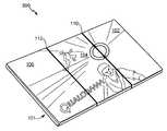
도 5 는 완전하게 펼쳐진 구성 (500) 의 도 1 의 전자 디바이스 (101) 를 도시한다. 제 1 패널 (102) 및 제 2 패널 (104) 은 실질적으로 공면이고, 제 2 패널 (104) 은 제 3 패널 (106) 과 실질적으로 공면이다. 패널들 (102, 104, 106) 은 제 1 접힘 위치 (110) 및 제 2 접힘 위치 (112) 에서 접촉하고 있을 수도 있어서, 제 1 패널 (102), 제 2 패널 (104) 및 제 3 패널 (106) 의 디스플레이 표면은 펼쳐진 3-패널 디스플레이 스크린을 실제로 형성한다. 예시된 바와 같이, 완전하게 펼쳐진 구성 (500) 에서, 디스플레이 표면 각각은 더 큰 이미지의 부분을 디스플레이하고, 각 개별 디스플레이 표면은 세로형 모드에서 더 큰 이미지의 부분을 디스플레이하고, 더 큰 이미지는 가로형 모드에서 유효 3-패널 스크린을 가로질러 연장한다. 특정한 실시형태에서, 패널들 (102, 104, 및 106) 은 완전하게 펼쳐진 구성 (500) 에서 실질적으로 유지되도록 락킹가능 (lockable) 할 수도 있다.FIG. 5 shows the
도 6 은 도 5 에 비교할 때 제 1 패널 (102), 제 2 패널 (104), 및 제 3 패널 (106) 상에 감소된 유효 디스플레이 표면을 갖는 완전하게 펼쳐진 구성 (600) 의 도 1 의 전자 디바이스 (101) 를 도시한다. 도 5 와 유사하게, 패널들 (102, 104, 및 106) 은 실질적으로 펼쳐지고, 포지션으로 락킹될 수도 있다. 그러나, 도 6 에 예시된 바와 같이, 패널들 (102, 104, 및 106) 각각의 세로형 모드의 상위 및 하위 표면부는 디스플레이 표면을 포함하지 않을 수도 있고, 대신에, 힌지, 마이크로폰, 스피커 또는 다른 하드웨어 피처 (미도시) 와 같은 하나 이상의 하드웨어 피처를 포함할 수도 있다.6 of FIG. 1 of a fully deployed
도 7 은 비디오 회의 구성 (700) 의 도 1 의 전자 디바이스 (101) 를 도시한다. 제 1 패널 (102) 은 제 2 패널 (104) 과 실질적으로 공면이도록 제 1 접힘 위치 (110) 에서 제 2 패널 (104) 에 커플링된다. 제 2 패널 (104) 및 제 3 패널 (106) 은 제 2 접힘 위치 (112) 에 따라 접힌 구성에 커플링되어서, 제 2 패널 (104) 및 제 3 패널 (106) 의 디스플레이 표면은 서로에 실질적으로 근접하며, 접힌 구성의 내부내에서 보호된다. 제 2 패널 (104) 상에서 접힌 제 3 패널 (106) 을 가짐으로써, 카메라 (720) 를 포함하는 제 3 패널 (106) 의 이면 (108) 은 전자 디바이스 (101) 의 사용자에게 노출된다. 제 3 패널 (106) 의 하부 에지는 마이크로폰 (722) 및 스피커 (724) 를 포함한다. 제 3 패널 (106) 의 하부 에지상에 도시되어 있지만, 마이크로폰 (722) 및 스피커 (724) 가 전자 디바이스 (101) 상의 다른 위치에 위치될 수도 있다는 것을 명백하게 이해해야 한다. 예를 들어, 도 32 에 관하여 예시하는 바와 같이, 마이크로폰 (722) 이 제 1 패널 (102) 의 디스플레이 표면의 상부에 위치될 수도 있고, 스피커 (724) 가 제 1 패널 (102) 의 디스플레이 표면의 하부 위치에 위치될 수도 있다. 비디오 회의 구성 (700) 은 전자 디바이스 (101) 의 사용자가 비디오 회의 콜의 관계자의 제 1 패널 (102) 의 디스플레이 표면상에서 이미지를 뷰 (view) 할 수 있게 하고, 동시에 사용자의 이미지를 캡처하고 캡처된 사용자의 이미지를 비디오 회의의 하나 이상의 관계자에게 제공하기 위해 카메라 (720) 의 시야에 위치될 수 있게 한다.FIG. 7 illustrates the
특정한 실시형태에서, 도 1 내지 도 7 의 전자 디바이스 (101) 는 기계적으로 접속될 수 있고 접힐 수 있는, 개별적으로 사용되거나 함께 사용될 수 있는 3개의 개별 터치 스크린 디스플레이 (102, 104, 및 106) 를 사용한다. 이것은, 전자 디바이스 (101) 의 형상 또는 구성에 기초하여 변경될 수 있는 다중의 사용자 인터페이스를 가능하게 한다. 다중의 구성가능한 사용자 인터페이스는 전자 디바이스 (101) 가 어떻게 접히거나 구성되는지에 의존하여 전자 디바이스 (101) 가 다중 타입의 디바이스로서 사용되는 것을 허용한다. 사용자가 단일 스크린 (완전하게 접힌 디바이스) 와 상호작용함으로써 시작할 수 있는 전자 디바이스 (101) 를 사용할 때, 전자 디바이스 (101) 가 상이한 물리적 구성으로 접히는 경우에 (애플리케이션 또는 세팅에 기초하여) 인터페이스가 자동으로 변경된다. 전자 디바이스 (101) 는 다중 스크린상에서 동시 애플리케이션을 실행하고, 디바이스 구성을 변경하는 사용자 상호작용에 기초하여 애플리케이션을 재구성하기 위해 구성될 수도 있다. 예를 들어, 전자 디바이스 (101) 는 하나의 물리적 구성에서의 단일 디스플레이 (102, 104, 또는 106) 에서 애플리케이션을 실행하고, 상이한 물리적 구성에서의 모든 3개의 디스플레이 (102, 104, 및 106) 에 걸쳐 애플리케이션을 실행하기 위해 구성될 수도 있다.In a particular embodiment, the
예를 들어, 전자 디바이스 (101) 가 닫힘 위치로 완전하게 접힐 때 (도 2 의 완전하게 접힌 구성 (200) 과 같이 하나의 스크린이 디스플레이됨), 전자 디바이스 (101) 는 작은 폼 팩터를 유지하고, 단축 사용자 인터페이스 뷰를 제공할 수 있다. 사용자 상호작용에 기초하여, 이러한 완전하게 접힌 구성은 전화, 단문 메시지 서비스 (SMS), 휴대 정보 단말기 (PDA) 타입 브라우저 애플리케이션, 키패드, 메뉴, 다른 인터페이스 엘리먼트, 또는 이들의 임의의 조합과 같은 애플리케이션을 디스플레이할 수 있다.For example, when the
완전하게 펼쳐질 때 (완전하게 펼쳐진 구성 (도 5 의 500 또는 도 6 의 600) 과 같이 모든 스크린이 디스플레이됨), 전자 디바이스 (101) 는 파노라마 뷰를 제공할 수도 있다. 사용자의 애플리케이션 선택에 기초하여, 파노라마 뷰는 예시적인 비제한적 예들로서 키보드를 갖거나 갖지 않는, 와이드 스크린 비디오, 애플리케이션 (예를 들어, 이메일, 텍스트 에디터) 을 갖는 데스크탑 환경, 또는 웹 브라우저와 유사한 인터페이스를 자동으로 디스플레이할 수 있다. 이들 인터페이스에 대한 상호작용은 이동 전화 타입 상호작용에 한정되는 대신에 그들의 네이티브 포맷과 유사할 수 있다.When fully expanded (all screens are displayed, such as a fully expanded configuration (500 in FIG. 5 or 600 in FIG. 6), the
디스플레이가 삼각형 형상으로 접힐 때 (도 4 의 여행용 시계 구성 (400) 과 같이, 삼각형의 하나의 부분은 역방향을 향한 디스플레이이고, 삼각형의 다른 부분은 순방향을 향한 디스플레이이고, 마지막은 프런트 아래에 접히거나 프런트에서 편평함), 구성은 방향성 사용자 인터페이스의 디스플레이를 자동으로 트리거할 수 있다. 다시 말해, 프런트 디스플레이(들)는 예시적인 비제한적인 예들로서, 게임 애플리케이션, 이메일, SMS, 전화, 알람 시계, 디지털 라디오, 또는 음악 플레이어와 같은 특정한 구성에 대한 디바이스 인터페이스를 나타낼 수도 있고, 백 디스플레이, 하부 디스플레이, 또는 양자는 유휴 또는 오프일 수도 있다.When the display is folded into a triangular shape (as in the
하나의 외부 디스플레이가 (도 3 의 서밍 구성 (300) 과 같이) 다른 디스플레이에 대해 대략 45도의 각으로 구성될 때, 전자 디바이스 (101) 는 인터페이스를 자동으로 변경할 수 있다. 예를 들어, 인터페이스는 텍스트 엔트리 디바이스일 수 있다. 45도 디스플레이는 키보드를 나타낼 수도 있지만 다른 것은 텍스트 엔트리 애플리케이션, 넌-PDA 타입 브라우저, 또는 다른 데스크탑형 애플리케이션을 디스플레이한다.When one external display is configured at an angle of approximately 45 degrees with respect to the other display (such as the
따라서, 전자 디바이스 (101) 는 기계적 트리거, 센서 정보 등에 기초하여 사용자 인터페이스 상호작용을 자동으로 변경하는 능력을 가질 수도 있다. 전자 디바이스 (101) 는 사용자가 다중의 메뉴를 브라우징하지 않고 디바이스에 대한 사용자의 기대를 예상하는 이점을 제공할 수도 있다. 전자 디바이스 (101) 가 완전하게 펼쳐질 때, 현재의 모바일 디바이스 보다 클 수도 있어서, 불충분한 스크린 영역의 종래의 모바일 디바이스의 결점을 극복한다. 전자 디바이스 (101) 의 사용자는 사용시에 그들의 필요성 및 선호도를 더욱 근접하게 매칭하기 위해 애플리케이션 인터페이스를 변경할 수 있다. 텍스트 에디터 또는 브라우저와 같은 복잡한 데스크탑형 인터페이스를 사용하는 종래의 모바일 디바이스의 사용자가 직면할 수도 있는 어려움은, 인터페이스를 다중의 디스플레이에 걸쳐 펼칠 수 있게 하는 전자 디바이스 (101) 에 의해 경감될 수도 있다.Thus, the
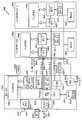
도 8 을 참조하면, 전자 디바이스의 특정한 예시적인 실시형태가 도시되어 있고 일반적으로 800 으로 표시된다. 디바이스 (800) 는 힌지 (미도시) 를 가로질러 접속부 (890) 의 세트를 통해 제 1 디스플레이 보드 (803) 및 제 2 디스플레이 보드 (805) 에 커플링된 메인 보드 (801) 를 포함한다. 보드들 (801, 803, 및 805) 각각은 도 1 내지 도 7 의 전자 디바이스 (101) 와 같은, 멀티-패널 힌지 디바이스의 개별 패널에 있을 수도 있다.Referring to Fig. 8, a particular exemplary embodiment of an electronic device is shown and is generally designated 800. The
메인 보드 (801) 는 디스플레이 (802), 메모리 (832) 에 커플링된 프로세서 (810), 디스플레이 제어기 (862), 터치스크린 제어기 (852), 무선 제어기 (840), 단거리 무선 인터페이스 (846), 코더/디코더 (CODEC; 834), 및 전력 관리 집적 회로 (PMIC; 880) 를 포함한다. 제 1 디스플레이 보드 (803) 는 디스플레이 제어기 (864), 터치스크린 제어기 (854), 및 하나 이상의 접음 구성/틸트 센서 (874) 에 커플링된 디스플레이 (804) 를 포함한다. 제 2 디스플레이 보드 (805) 는 디스플레이 제어기 (866), 터치스크린 제어기 (856), 및 하나 이상의 접음 구성/틸트 센서 (876) 에 커플링된 디스플레이 (806) 를 포함한다. 제 1 디스플레이 보드 (803) 는 제 1 고속 직렬 링크 (892) 와 같은 제 1 통신 경로를 통해 메인 보드 (801) 에 커플링된다. 제 2 디스플레이 보드 (805) 는 제 2 고속 직렬 링크 (894) 와 같은 제 2 통신 경로를 통해 메인 보드 (801) 에 커플링된다. 제 1 디스플레이 보드 (803) 및 제 2 디스플레이 보드 (805) 는 각각 배터리 (884 및 886) 를 갖고, 이 배터리는 PMIC (880) 와 배터리 (884 및 886) 사이에서 적어도 1.5 암페어(A) 를 전도할 수도 있는 전력 라인 (896) 을 통해 PMIC (880) 에 커플링된다. 특정한 실시형태에서, 카메라 (820) 및 전력 입력 (882) 이 메인 보드 (801) 에 또한 커플링된다.The
프로세서 (810) 는 하나 이상의 ARM-타입 프로세서, 하나 이상의 디지털 신호 프로세서 (DSP), 다른 프로세서, 또는 이들의 임의의 조합을 포함할 수도 있다. 프로세서 (810) 는 대표적인 메모리 (832) 와 같은 하나 이상의 컴퓨터 판독가능한 매체에 액세스할 수 있다. 메모리 (832) 는 데이터 (미도시) 및 소프트웨어 (833) 와 같은 프로세서 실행가능한 명령들을 저장한다. 일반적으로, 소프트웨어 (833) 는 프로세서 (810) 에 의해 실행가능한 프로세서 실행가능한 명령들을 포함하고, 애플리케이션 소프트웨어, 운영 시스템 소프트웨어, 다른 타입의 프로그램 명령들, 또는 이들의 임의의 조합을 포함할 수도 있다. 메모리 (832) 가 프로세서 (810) 에 대해 외부적으로 도시되어 있지만, 다른 실시형태에서는, 메모리 (832) 는 캐시, 하나 이상의 레지스터 또는 레지스터 파일, 프로세서 (810) 에서의 다른 저장 디바이스, 또는 이들의 임의의 조합에서와 같이 프로세서 (810) 에 대해 내부에 있을 수도 있다.The
프로세서 (810) 는 또한, 제 1 디스플레이 패널 (803) 및 제 2 디스플레이 패널 (805) 각각에서 접음 구성 및 틸트 센서 (874 및 876) 과 같은 접음 구성 센서에 커플링된다. 예시적인 예에서, 디바이스 (800) 는 도 1 의 전자 디바이스 (101) 일 수도 있으며, 센서 (874 및 876) 는 도 2 에 예시된 완전하게 접힌 구성, 도 3 에 예시된 서밍 구성, 도 4 에 예시된 여행용 시계 구성, 도 5 및 도 6 에 예시된 완전하게 펼쳐진 구성, 또는 도 7 에 예시된 비디오 회의 구성 중 하나 이상으로서 디바이스 (800) 의 접음 구성을 검출하도록 구성될 수도 있다.The
디스플레이 제어기 (862, 864, 및 866) 는 디스플레이 (802, 804, 및 806) 를 제어하도록 구성된다. 특정한 실시형태에서, 디스플레이 (802, 804, 및 806) 는 도 1 내지 도 7 에 예시된 디스플레이 표면 (102, 104, 및 106) 에 대응할 수도 있다. 디스플레이 제어기 (862, 864, 및 866) 는 디바이스 (800) 의 구성에 따라 디스플레이 (802, 804, 및 806) 에서 디스플레이하기 위한 그래픽 데이터를 제공하기 위해 프로세서 (810) 에 응답하도록 구성될 수도 있다. 예를 들어, 디바이스 (800) 가 완전하게 접힌 구성에 있을 때, 디스플레이 제어기 (862, 864, 및 866) 는 그래픽 사용자 인터페이스를 디스플레이하기 위해 제 1 디스플레이 (802) 를 제어할 수도 있고, 다른 디스플레이 (804 및 806) 를 파워 다운 (power down) 하거나 사용하지 않을 수도 있다. 다른 예로서, 디바이스 (800) 가 완전하게 펼쳐진 구성에 있을 때, 디스플레이 제어기 (862, 864, 및 866) 는 이미지의 각각의 부분을 각각 디스플레이하여 모든 3개의 디스플레이 (802, 804, 및 806) 를 스팬하는 단일 유효 스크린으로서 동작하도록 디스플레이 (802, 804, 및 806) 를 제어할 수도 있다.The
특정한 실시형태에서, 디스플레이 (802, 804, 및 806) 각각은 터치스크린 제어기 (852, 854, 또는 856) 각각에 커플링되는 각각의 터치스크린을 통해 사용자 입력에 응답한다. 터치스크린 제어기 (852, 854, 및 856) 는 사용자 입력을 나타내는 디스플레이 (802, 804, 및 806) 로부터 신호를 수신하고, 사용자 입력을 표시하는 프로세서 (810) 로 데이터를 제공하도록 구성된다. 예를 들어, 프로세서 (810) 는 제 1 디스플레이 (802) 상의 애플리케이션 아이콘에서 더블-탭 (double-tap) 을 표시하는 사용자 입력에 응답할 수도 있고, 사용자 입력에 응답하여 디스플레이 (802, 804, 또는 806) 중 하나 이상에서 애플리케이션을 론치할 수도 있고 애플리케이션 윈도우를 디스플레이할 수도 있다.In a particular embodiment, each of the
특정한 실시형태에서, 대응하는 디스플레이 (802, 804, 및 806) 와 함께 각각의 디스플레이 제어기 (862, 864, 및 866) 및 각각의 터치스크린 제어기 (852, 854, 및 856) 을 가짐으로써, 패널들 사이에서 통신된 데이터량이, 개별 패널들 상에서 제어기 및 대응하는 디스플레이를 갖는 다른 실시형태들과 비교하여 감소될 수도 있다. 그러나, 다른 실시형태에서, 디스플레이 제어기 (862, 864, 또는 866), 또는 터치스크린 제어기 (853, 854, 또는 856) 중 2개 이상은 모든 3개의 디스플레이 (802, 804, 및 806) 을 제어하는 단일 제어기로와 같이 결합될 수도 있다. 추가로, 3개의 디스플레이 (802, 804, 및 806) 가 예시되어 있지만, 다른 실시형태에서는, 디바이스 (800) 는 3개 보다 많거나 적은 디스플레이를 포함할 수도 있다.In a particular embodiment, by having each of the
고속 직렬 링크 (892 및 894) 는 고속 양방향 직렬 링크일 수도 있다. 예를 들어, 링크 (892 및 894) 는 모바일 디스플레이 디지털 인터페이스 (MDDI) 타입 링크일 수도 있다. 터치스크린 데이터 및 센서 데이터는 패널 (803 및 805) 로부터 프로세서 (810) 로 리턴하기 위해 직렬 스트림에 포함될 수도 있어서, 오직 4개의 차동쌍만이 패널들 (801, 803, 및 805) 사이에서 각각의 힌지를 가로질러 시그널링하기 위해 사용될 수도 있다.The high speed
특정한 실시형태에서, 센서 (874 및 876) 는 하나 이상의 센서에서 수신된 입력에 기초하여 디바이스 (800) 의 접음 구성을 검출하도록 구성될 수도 있다. 예를 들어, 센서 (874 및 876) 중 하나 이상은 하나 이상의 가속도계, 경사계, 힌지 검출기, 다른 검출기, 또는 이들의 임의의 조합으로부터의 입력을 포함하거나 수신할 수도 있다. 센서 (874 및 876) 는 디바이스 (800) 의 검출된 접음 구성을 표시하는 정보를 프로세서 (810) 에 제공할 수도 있다. 센서 (874 및 876) 는 디바이스 (800) 의 이웃하는 디스플레이 패널에 대한 디스플레이 패널의 회전각을 검출함으로써 상대적 접음 위치에 응답할 수도 있다. 센서 (874 및 876) 는 또한, 디바이스 (800) 의 하나 이상의 디스플레이 패널에 커플링된 가속도계 또는 경사계와 같은 하나 이상의 다른 센서에 응답할 수도 있다.In certain embodiments,
도 8 에 예시된 바와 같이, 코더/디코더 (CODEC; 834) 는 또한 프로세서 (810) 에 커플링될 수 있다. 스피커 (822) 및 마이크로폰 (824) 이 CODEC (834) 에 커플링될 수 있다. 도 8 은 또한, 무선 제어기 (840) 가 프로세서 (810) 및 무선 안테나 (842) 에 커플링될 수 있고, 광역 네트워크 (WAN) 와 같은 무선 네트워크를 통해 통신하도록 디바이스 (800) 를 인에이블할 수 있다는 것을 나타낸다. 프로세서 (810) 는 디바이스 (800) 가 인커밍 콜을 수신할 때, 디스플레이 (802, 804, 및 806) 중 하나 이상에서 발신자 식별 또는 발신자 번호와 같은 콜 표시를 디스플레이하기 위해 무선 제어기 (840) 에 응답할 수도 있다. 프로세서 (810) 는 센서 (874 및 876) 로부터의 입력에 기초하여 결정되는 디바이스 (800) 의 접음 구성에 적어도 부분적으로 기초하여 콜 표시를 디스플레이하기 위해 크기, 위치, 및 배향 뿐만 아니라 특정한 디스플레이 (802, 804, 및 806) 를 결정할 수도 있다. 예를 들어, 콜 표시는 접음 구성에 기초하여 크기, 위치, 및 배향을 갖는 하나 이상의 다른 애플리케이션상에서 팝업 윈도우 또는 텍스트로서 디스플레이될 수도 있다.As illustrated in FIG. 8, a coder / decoder (CODEC) 834 may also be coupled to the
특정한 실시형태에서, 디바이스 (800) 는 모든 접음 구성에서 무선 전화 통신을 위해 동작가능하도록 구성된다. 특정한 실시형태에서, 프로세서 (810) 는 안테나 (848) 를 통해 헤드셋 (850) 에 커플링될 수도 있는 단거리 무선 인터페이스 (846) 에 커플링된다. 단거리 무선 인터페이스 (846) 는 블루투스 네트워크와 같은 애드-혹 무선 네트워크를 통해, 이어피스 및 마이크로폰을 포함하는 디바이스와 같은 헤드셋 (850) 에 무선으로 커플링될 수도 있다. 프로세서 (810) 는 인커밍 콜에 응답하여 콜 표시를 디스플레이하거나 헤드셋 (850) 에 경고할지를 결정하도록 로직을 구현할 수도 있다. 예를 들어, 프로세서 (810) 는, 디바이스 (800) 가 완전하게 펼쳐진 구성에 있고 멀티미디어 파일 또는 스트리밍 미디어가 모든 디스플레이 (802, 804, 및 806) 에 걸쳐 디스플레이될 때 헤드셋 (850) 에 자동으로 경고할 수도 있고, 그렇지 않으면 콜 표시를 디스플레이할 수도 있다.In a particular embodiment, the
특정한 실시형태에서, 도 8 의 하나 이상의 컴포넌트는 디바이스 패널 중 하나 이상에 근접하여 또는 그 안에 위치될 수도 있다. 예를 들어, 프로세서 (810) 는 중앙 패널내에 위치될 수도 있고, 외부 패널은 배터리 (884 및 886) 를 각각 저장할 수도 있다. 특정한 실시형태에서, 패널은 디바이스가 서밍 구성에서 직립 (upright) 을 유지하는 것을 가능하게 하기 위한 방식으로 가중될 수도 있다.In certain embodiments, one or more of the components of Fig. 8 may be located proximate to or within one or more of the device panels. For example, the
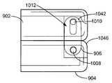
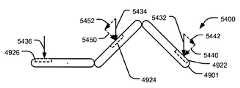
도 9 를 참조하면, 전자 디바이스의 특정한 예시적인 실시형태가 도시되어 있고, 일반적으로 900 으로 표시된다. 디바이스 (900) 는 제 1 패널 (902) 및 제 2 패널 (904) 을 포함한다. 제 1 패널 (902) 및 제 2 패널 (904) 은 패널들 (902 및 904) 의 상부 에지 및 하부 에지 근처의 리세스된 힌지 (905) 를 통해 커플링된다. 특정한 실시형태에서, 전자 디바이스 (900) 는 사용자에 의해 사용을 위한 다양한 구성으로 조작될 수 있고, 구성 변경에 응답하여 소프트웨어 또는 디스플레이된 이미지를 자동으로 조절할 수도 있다. 예시된 실시형태에서, 전자 디바이스 (900) 는 도 1의 전자 디바이스 (101), 도 8 의 전자 디바이스 (800), 또는 이들의 임의의 조합의 2-패널 실시형태이다. 특정한 실시형태에서, 리세스된 힌지 (905) 는 커플링 부재 (906) 를 포함한다. 도 9 는 제 1 패널 (902) 및 제 2 패널 (904) 의 표면과 실질적으로 동일 높이이고, 제 1 패널에 의해 정의된 제 1 개구 (1040) 및 제 2 패널 (904) 에 의해 정의된 제 2 개구 (1044) 를 통해 가시적인 커플링 부재 (906) 를 도시하는 리세스된 힌지 (905) 의 확대도를 포함한다.Referring to Fig. 9, a particular exemplary embodiment of an electronic device is shown and is generally designated 900. The
접음 디스플레이 패널 (902 및 904) 은, 완전하게 펼쳐질 때, 광 스크린 텔레비전과 유사한 파노라마 뷰를 제공할 수도 있고, 닫힌 위치로 완전하게 접힐 때, 작은 폼 팩터를 제공할 수도 있고, 종래의 셀룰러 폰과 유사한 단축 뷰를 여전히 제공할 수도 있다. 평행이동 및 회전을 포함하는 더욱 복잡한 모션을 제공하는 리세스된 힌지 (905) 와 같은 작은 힌지가 디스플레이 패널 갭을 감소시키고 더욱 연속적인 타일링 (tiling) 을 생성하기 위해 사용될 수 있고, 다수의 디스플레이 또는 패널을 갖는 하나 이상의 설계에서 사용될 수도 있다.The folded
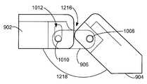
도 10 은 도 9 의 디바이스 (900) 의 측면 부분 단면도를 예시한다. 제 1 패널 (902) 은 제 1 패널 (902) 내의 제 1 캐비티 (1042) 와 통신하고 있는 제 1 개구 (1040) 를 정의한다. 제 2 패널 (904) 은 제 2 패널 (904) 에서의 제 2 캐비티 (1046) 와 통신하고 있는 제 2 개구 (1044) 를 정의한다. 커플링 부재 (906) 는 제 1 핀 (1010) 과 같은 제 1 피벗 부재, 및 제 2 핀 (1008) 과 같은 제 2 피벗 부재에 커플링된다. 제 1 핀 (1010) 및 제 2 핀 (1008) 은 제 1 패널 (902) 이 커플링 부재 (906) 에 회전가능하게 커플링될 수 있게 하며, 제 2 핀 (1008) 은 제 2 패널 (904) 이 커플링 부재 (906) 에 회전가능하게 커플링될 수 있게 한다. 그 결과, 제 1 패널 (902) 및 제 2 패널 (904) 은 서로에 회전가능하게 커플링된다. 또한, 제 1 패널 (902) 및 제 2 패널 (904) 각각에서 정의된 개구 (1040 및 1044) 는 커플링 부재 (906) 가 그 안에 삽입될 수 있고, 커플링 부재 (906) 에 관한 패널 (902 및 904) 각각의 회전 모션의 범위를 가능하게 하기 위해 형성된다. 또한, 제 1 핀 (1010) 은 제 2 패널 (904) 에 대한 제 1 패널 (902) 의 수평 이동을 가능하게 하기 위해 제 1 캐비티 (1042) 내의 슬롯 (1012) 내에 맞물려서, 제 1 패널 (902) 은 리세스된 힌지 (905) 가 슬롯 (1012) 의 제 1 단부에서 제 1 핀 (1010) 을 갖는 펼쳐진 구성에 있을 때 제 2 패널 (904) 에 대한 모션의 범위를 갖는다. 또한, 제 1 패널 (902) 은 리세스된 힌지 (905) 가 슬롯 (1012) 의 제 2 단부에서 제 1 핀 (1010) 을 갖는 수축된 구성에 있을 때 제 2 패널 (904) 에 대한 모션의 제 2 범위를 갖고, 여기서, 모션의 제 1 범위는 모션의 제 2 범위 보다 크다. 도 15 내지 도 20 에 관하여 논의될 바와 같이, 센서가 제 2 패널 (904) 에 대한 제 1 패널 (902) 의 상대적 배향을 검출하기 위해 리세스된 힌지 (905) 에 커플링될 수도 있다.10 illustrates a cross-sectional side view of
예시된 바와 같이, 제 1 개구 (1040) 는 커플링 부재 (906) 의 적어도 제 1 부분을 수용하도록 치수화되고, 제 1 부분은 핀 (1010) 에 커플링된 커플링 부재 (906) 의 부분을 포함한다. 또한, 제 2 개구 (1044) 는 커플링 부재 (906) 의 적어도 제 2 부분을 수용하도록 치수화되고, 제 2 부분은 제 2 핀 (1008) 에 커플링된 부분을 포함한다. 또한, 제 1 캐비티 (1042) 는 제 1 핀 (1010) 이 슬롯 (1012) 내의 가장 안쪽의 위치에 있을 때 커플링 부재 (906) 를 수용하기 위한 펼쳐진 리세스된 컴포넌트 (1014) 를 포함한다.The
도 11 은 각이 진 구성 (1100) 의 도 9 의 전자 디바이스 (900) 를 도시한다. 제 1 패널 (902) 은 커플링 부재 (906) 를 포함하는 것으로서 예시된, 리세스된 힌지 (905) 를 통해 제 2 패널 (904) 에 대한 각에서 배향된다. 도 11 은 도 9 와 비교하여 제 2 패널 (904) 의 제 2 개구 (1044) 의 상이한 영역을 통해 연장하는 커플링 부재 (906) 를 예시하는 리세스된 힌지 (905) 의 클로즈업 도면을 포함한다.11 shows the
도 12 는 커플링 부재 (906) 를 통해 제 2 패널 (904) 에 회전가능하게 커플링된 제 1 패널 (902) 을 예시한다. 커플링 부재 (906) 는 슬롯 (1012) 에 맞물린 제 1 핀 (1010) 을 통해 제 1 패널 (902) 에 회전가능하게 커플링되고, 제 2 핀 (1008) 을 통해 제 2 패널 (904) 에 회전가능하게 커플링된다. 도 12 에 예시된 바와 같이, 제 2 패널 (904) 은 각 스톱 (angle stop; 1216) 을 제공하기 위해 제 1 패널 (902) 과 접한다. 도 12 의 구성에서, 제 2 패널 (904) 은 패널 (902) 의 표면에 대해 레이 플랫 (lay flat) 하기 위해 완전하게 접힌 위치로 내부 방향에서 회전될 수도 있고, 제 1 패널 (902) 에 대하여 소정의 각 (1218) 으로 외부 방향에서 회전될 수도 있고 각 스톱 (1216) 을 통해 다른 회전 분리가 방지될 수도 있다. 각 스톱 (1216) 은 제 1 패널 (902) 에 대해 실질적으로 135도로서 도 12 의 실시형태에 예시되는 소정의 각 (1218) 에서 제 2 패널 (904) 을 홀딩할 수도 있다.12 illustrates a
도 13 을 참조하면, 도 9 에 도시된 전자 디바이스 (900) 는 완전하게 접힌 구성 (1300) 으로 예시된다. 완전하게 접힌 구성 (1300) 은 실질적으로 제 2 패널 (904) 에 근접한 스크린을 포함하는 디스플레이 표면과 같은 제 1 표면을 갖는 제 1 패널 (902) 을 갖는다. 리세스된 힌지 (905) 는, 완전하게 접힌 구성 (1300) 에서 디바이스 높이를 감소시키기 위해 제 1 패널 (902) 이 제 2 패널 (904) 에 실질적으로 근접하게 위치될 수 있게 하기 위한 수축된 구성으로 예시되어 있다. 리세스된 힌지 (905) 의 확대도가 제 1 패널 (902) 의 제 1 개구 (1040) 및 제 2 패널 (904) 의 제 2 개구 (1044) 를 통해 연장하는 커플링 부재 (906) 를 도시하는 도 13 에 예시되어 있다.Referring to FIG. 13, the
도 14 는 완전하게 접힌 구성 (1300) 의 측면 부분 단면도를 예시한다. 도 14 에 예시된 바와 같이, 제 1 패널 (902) 은 제 1 패널 (902) 의 제 1 캐비티 (1042) 및 제 2 패널 (904) 의 제 2 캐비티 (1046) 내에 완전하게 있는 커플링 부재 (906) 로 제 2 패널 (904) 에 대해 완전하게 접힌다. 예시된 바와 같이, 커플링 부재 (906) 는 슬롯 (1012) 의 하나의 말단에서 제 1 캐비티 (1042) 에 맞물리는 제 2 핀 (1010) 을 갖고, 이것은 제 1 패널 (902) 및 제 2 패널 (904) 이 서로에 실질적으로 근접하게 위치되게 하고, 예시된 바와 같이, 서로에 대해 실질적으로 플랫하게 한다.Fig. 14 illustrates a side partial cross-sectional view of a fully folded
특정한 실시형태에서, 리세스된 힌지 (905) 에는 센서가 디텐트 (detent) 되고 장착될 수도 있어서, 멀티-폴드 모바일 디바이스는 도 15 내지 도 17 및 도 18 내지 도 20 에 관하여 더욱 상세히 논의되는 바와 같이, 힌지 센서로부터의 피드백에 기초하여 디스플레이 이미지 배향 및 컨텐츠를 조절할 수 있다. 힌지는 예를 들어, 예시적인 비제한적인 예들로서 위치를 판독하기 위해, 압력 센서, 전기 컨택트, 홀 센서, 광학 또는 유도 검출을 사용할 수도 있다. 피드백은 2개 이상의 힌지 위치 또는 회전으로부터 수신될 수도 있다. 힌지는 접음 패널이 소정의 위치에 설정되게 할 수도 있고, 멀티-폴드 모바일 디바이스는 소정의 위치에서의 접음 패널의 검출에 적어도 부분적으로 기초하여 디스플레이 이미지 배향 및 컨텐츠 또는 사용자 인터페이스를 설정할 수도 있다. 예를 들어, 힌지는 볼 디텐트될 수도 있고, 완전하게 열리고 완전하게 닫힌 것 사이에서 하나 이상의 중간 위치 또는 스탑을 가질 수도 있거나, 접음 패널이 다중 위치에 홀딩되게 하기 위한 다른 구성을 가질 수도 있다. 예를 들어, 하나 이상의 힌지는 스프링-바이어스될 수도 있어서, 패널은 재포지셔닝을 위해 약간 분리될 수 있고 상이한 구성으로 스냅 백 (snap back) 하는 것이 허용될 수 있다. 또한, 전자 디바이스는 하나의 폴드에서 제 1 타입의 힌지 및 다른 폴드에서 제 2 타입의 힌지를 가질 수도 있다.In a particular embodiment, the sensor may be detented and mounted on the recessed
예를 들어, 특정한 실시형태에서, 디텐트된 힌지는 디스플레이 이미지가 가로형 모드에서 활성이고 뷰가능하면서, 패널이 플랫하게 또는 일 평면에 배치되게 할 수 있다. 멀티-폴드 디바이스가 플랫하지 않으면, 좌측 패널은 세로형 배향에서 터치 패널 키보드를 포함할 수도 있고, 다른 디스플레이는 세로형 모드에서 결합될 수도 있다. 멀티-폴드 디바이스가 닫힐 때, 우측 디스플레이는 활성될 수도 있고, 세로형 배향에서, 나머지 디스플레이가 오프되고 비활성된다. 기능적 흐름은 특정한 위치에 설정된 멀티-폴드 디바이스를 수반할 수 있고, 하나 이상의 스마트 힌지는 위치를 판독하고, 이미지 또는 사용자 인터페이스는 그 위치의 판독에 응답하여 조절한다. 디스플레이 이미지 또는 사용자 인터페이스에 대한 매우 다양한 가능한 구성이 멀티-폴드 디바이스에서의 디텐트된 힌지에 의해 인에이블될 수도 있고, 특정한 실시형태에서, 작은 폼 팩터 디바이스가 대형 스크린 멀티미디어 디바이스로서 사용되도록 확장하기 위해 인에이블될 수도 있다.For example, in certain embodiments, the detented hinge may cause the display image to be flat and in one plane, while the display image is active and viewable in the landscape mode. If the multi-fold device is not flat, the left panel may include a touch panel keyboard in a vertical orientation, and the other display may be combined in a vertical mode. When the multi-fold device is closed, the right display may be activated, and in the vertical orientation, the remaining display is turned off and disabled. The functional flow may involve a multi-fold device set at a specific location, one or more smart hinges read the location, and the image or user interface adjusts in response to reading the location. A wide variety of possible configurations for the display image or the user interface may be enabled by the detented hinge in the multi-fold device, and in certain embodiments, to extend the small form factor device to be used as a large screen multimedia device May be enabled.
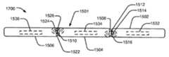
도 15 는 접힌 구성 (1500) 의 3개 패널 전자 디바이스의 특정한 예시적인 실시형태를 예시한다. 3개 패널 디바이스 (1501) 는 제 1 패널 (1502), 제 2 패널 (1504), 및 제 3 패널 (1506) 을 포함한다. 제 1 패널 (1502) 은 점선으로 도시된 리세스된 힌지로서 예시되어 있는 제 1 힌지 (1505) 를 통해 제 2 패널 (1504) 에 커플링된다. 제 2 패널 (1504) 은 제 2 힌지 (1507) 를 통해 제 3 패널 (1506) 에 커플링된다. 제 1 패널 (1502) 은 다양한 구성에서 제 2 패널 (1504) 의 제 1 단부 (1508) 와 접촉할 수도 있는 하나 이상의 전극, 압력 센서, 또는 이들의 임의의 조합을 포함할 수도 있는 제 1 센서 (1512), 제 2 센서 (1514), 및 제 3 센서 (1516) 를 포함한다. 또한, 제 2 패널 (1504) 은 다양한 구성에서 제 3 패널 (1506) 의 제 1 센서 (1522), 제 2 센서 (1524), 및 제 3 센서 (1526), 또는 이들의 임의의 조합과 접촉할 수도 있는 제 2 단부 (1510) 를 갖는다. 제 1 패널 (1502) 은 제 1 내부 센서 (1532) 를 포함하고, 제 2 패널 (1504) 은 제 2 내부 센서 (1534) 를 포함하고, 제 3 패널 (1506) 은 제 3 내부 센서 (1536) 를 포함한다. 예시적인 실시형태에서, 3개 패널 디바이스 (1501) 는 도 1 내지 도 7 의 전자 디바이스 (101), 도 8 의 전자 디바이스 (800), 도 9 내지 도 14 의 전자 디바이스의 3개 패널 실시형태, 또는 이들의 임의의 조합일 수도 있다.15 illustrates a particular exemplary embodiment of a three-panel electronic device in a folded
특정한 실시형태에서, 3개 패널 디바이스 (1501) 는 센서들 (1512 내지 1516 및 1522 내지 1526) 에서의 액티비티에 기초하여 구성을 인식할 수도 있다. 특히, 제 2 패널 (1504) 에 대한 제 1 패널 (1502) 의 상대적 배향은 센서들 (1512-1516) 중 하나 이상과 제 1 에지 (1508) 사이의 접촉의 존재 또는 부재를 통하는 것과 같이 제 1 힌지에서 검출될 수도 있다. 또한, 제 3 패널 (1506) 과 제 2 패널 (1504) 의 상대적 배향은 제 2 에지 (1510) 와 센서들 (1512-1516) 중 하나 이상 사이의 접촉의 존재 또는 부재를 통해 검출되거나 감지될 수도 있다. 예시되어 있는 바와 같이, 구성 (1500) 에서의 전자 디바이스 (1501) 는 완전하게 접힌 구성에 있다. 유사하게, 센서들 (1532, 1534, 1536) 중 하나 이상은 가속도계, 경사를 측정하기 위한 경사계 센서, 자이로스코프와 같은 상대적 이동을 측정하기 위한 센서, 다른 타입의 센서, 또는 이들의 임의의 조합을 포함할 수도 있다. 내부 센서들 (1532-1536) 뿐만 아니라 이들 센서 (1512-1516 및 1522-1526) 와 같은 힌지에서 센서들을 사용함으로써, 접음 구성, 상대적 또는 절대적 정렬, 디바이스의 경사 또는 다른 물리적 구성은 도 8 의 프로세서 (810) 와 같은 디바이스를 제어하는 프로세서를 통해 검출될 수도 있고 그 프로세서에 응답할 수도 있다.In a particular embodiment, the three
예를 들어, 센서들 (1512-1516 및 1522-1526), 및 내부 센서들 (1532-1536) 은 도 8 의 접음 구성 센서 (826) 에 포함될 수도 있거나 공급될 수도 있다. 디바이스는 적어도 3개의 소정의 구성의 세트로부터 디바이스 구성을 검출하기 위해 힌지에 커플링된 센서에 응답하는 도 8 의 프로세서 (810) 와 같은 프로세서를 포함할 수도 있다. 센서는 홀 센서, 광학 센서, 또는 유도 센서 중 적어도 하나의 센서를 포함할 수도 있다. 힌지들 중 하나 이상은 제 2 패널에 대한 제 1 패널의 안정한 펼쳐진 구성, 접힌 구성, 및 중간 구성을 가능하게 하기 위해 디텐트될 수도 있고, 프로세서는 적어도 3개의 소정의 구성에 대응하는 적어도 3개의 소정의 동작 모드를 갖는 소프트웨어 애플리케이션을 실행하도록 구성될 수도 있다. 프로세서는 또한, 검출된 디바이스 구성에 기초하여 소프트웨어 애플리케이션의 동작 모드를 조절할 뿐만 아니라, 검출된 디바이스 구성에 기초하여 제 1 디스플레이 표면, 제 2 디스플레이 표면, 및 제 3 디스플레이 표면에서 디스플레이된 사용자 인터페이스를 조절하도록 구성될 수도 있다. 예를 들어, 제 1 소정의 구성에서, 제 1 디스플레이 표면, 제 2 디스플레이 표면, 및 제 3 디스플레이 표면은 가로형 구성에서 단일 스크린을 에뮬레이션하도록 구성될 수도 있고, 제 2 소정의 구성에서, 제 1 디스플레이 표면은 활성일 수도 있고, 제 2 디스플레이 표면 및 제 3 디스플레이 표면은 비활성일 수도 있으며, 제 3 소정의 구성에서, 키보드가 제 3 디스플레이 표면에 디스플레이될 수도 있고 제 1 디스플레이 표면 및 제 2 디스플레이 표면은 세로형 구성에서 단일 스크린을 에뮬레이션하도록 구성될 수도 있다. 센서들 (1532-1536) 이 내부 센서들로서 도시되어 있지만, 다른 실시형태들에서, 센서들 중 하나 이상은 내부일 필요는 없으며, 대신에, 각각의 패널의 표면, 또는 패널들에 대한 다른 위치들에 커플링될 수도 있다.For example, sensors 1512-1516 and 1522-1526, and internal sensors 1532-1536 may be included in or supplied to the folded configuration sensor 826 of FIG. The device may include a processor, such as
도 16 은 여행용 시계 구성 (1600) 의 도 15 의 전자 디바이스 (1501) 를 도시한다. 제 1 패널 (1502) 은 센서들 (1512-1516) 및 제 1 내부 센서 (1532) 를 포함한다. 제 1 센서 (1512) 및 제 2 센서 (1514) 는 제 2 패널 (1504) 의 제 1 단부 (1508) 와 접촉하고 있지 않고, 제 3 센서 (1516) 는 제 1 단부 (1508) 와 접촉하고 있고, 이것은 제 1 패널 (1502) 이 제 2 패널 (1504) 에 대해 실질적으로 90도 상대적 배향인 제 1 각 스탑에 위치된다는 것을 나타낸다. 유사하게, 제 2 패널 (1504) 의 제 2 에지 (1510) 는 제 3 패널 (1506) 의 제 2 센서 (1524) 와 접촉하고 있지만, 제 3 패널 (1506) 의 제 1 센서 (1522) 또는 제 3 센서 (1526) 와는 접촉하고 있지 않다. 따라서, 디바이스 (1501) 의 프로세서는 제 2 패널 (1504) 이 도 16 에 예시된 바와 같이 135도 상대적 배향에서와 같이 제 2 각 스탑에서 제 3 패널 (1506) 과 상대적 정렬되어 있다는 것을 결정할 수도 있다. 또한, 제 2 패널 (1504) 의 내부 센서 (1534) 는, 제 2 패널 (1504) 이 중력 방향 인력에 대해 경사져 있다는 것을 나타낼 수도 있고, 제 3 패널 (1506) 의 내부 센서 (1536) 는, 제 3 패널 (1506) 이 상대적으로 수평 배향이고, 정지되어 있다는 것을 나타낼 수도 있어서, 전자 디바이스 (1501) 는, 여행용 시계 구성 (1600) 에 놓였다는 것을 인식할 수도 있다.Fig. 16 shows the
도 17 은 완전하게 펼쳐진 구성 (1700) 의 도 15 의 전자 디바이스 (1501) 를 도시한다. 제 1 패널 (1502) 및 제 2 패널 (1504) 은, 제 2 패널 (1504) 의 제 1 단부 (1508) 가 제 1 패널 (1502) 의 제 1 센서 (1512) 및 제 3 센서 (1516) 와 실제 접촉하고 있지만, 제 2 센서 (1514) 와는 접촉하고 있지 않도록 위치되고, 이것은 제 1 패널 (1502) 및 제 2 패널 (1504) 이 제 3 각 스탑에서 엔드-투-엔드 (end-to-end) 정렬되어 있고 대략 180도의 상대적 회전 배향에서 실질적으로 공면이다는 것을 나타낸다. 유사하게는, 제 2 패널 (1504) 및 제 3 패널 (1506) 은 또한, 제 3 패널 (1506) 의 제 1 센서 (1522) 및 제 3 센서 (1526) 와 접촉하고 있지만, 제 2 센서 (1524) 와 접촉하고 있지 않은 제 2 에지 (1510) 로 인해 검출될 수도 있기 때문에 제 3 각 스탑에서 실질적으로 공면이다. 또한, 내부 센서들 (1532, 1534 및 1536) 중 하나 이상은 가속도, 경사, 하나 이상의 상대적 위치, 또는 이들의 임의의 조합을 나타내기 위해 사용될 수도 있다. 패널들 (1502, 1504, 및 1506) 의 하나 이상의 각 스탑 또는 나머지 위치에서, 전자 센서, 압력 센서, 자기장 검출기, 또는 이들의 임의의 조합과 같은 센서들을 포함함으로써, 전자 디바이스 (1501) 는 패널들 (1502-1506) 중 하나 이상 사이의 상대적 배향을 결정할 수도 있어서, 이것은 전자 디바이스 (1501) 가 현재 있는 하드웨어 구성을 결정하고, 센서들 (1512-1516 및 1522-1526) 이 각각 맞물리고 맞물림해제될 때 하드웨어 구성에서의 변경을 검출하게 한다.Fig. 17 shows the
도 18 은 완전하게 접힌 구성 (1800) 의 제 1 패널 (1802), 제 2 패널 (1804), 및 제 3 패널 (1806) 을 갖는 전자 디바이스 (1801) 를 도시한다. 제 1 패널 (1802) 은 제 1 센서 (1812) 를 포함하는 리세스된 힌지를 통해 제 2 패널 (1804) 에 회전가능하게 커플링된다. 제 2 패널 (1804) 은 제 2 센서 (1822) 를 포함하는 리세스된 힌지를 통해 제 3 패널 (1806) 에 커플링된다. 제 2 패널 (1804) 은 또한, 하나 이상의 내부 센서 (1834) 를 포함한다. 특정한 실시형태에서, 리세스된 힌지내의 제 1 센서 (1812) 는 제 1 센서 (1812) 에서 검출될 제 2 패널 (1804) 에 관한 제 1 패널 (1802) 의 상대적 포지셔닝을 인에이블하기 위해, 제 2 패널 (1804) 에 대한 제 1 패널 (1802) 의 회전 정렬, 또는 커플링 부재, 힌지의 핀들 중 하나 이상, 다른 메카니즘을 통한 중력의 방향, 또는 이들의 임의의 조합에 대한 패널들 (1802 및 1804) 중 하나 이상 사이의 회전의 정도를 검출할 수도 있다. 제 2 센서 (1822) 는 제 2 패널 (1804) 과 제 3 패널 (1806) 사이의 상대적 배향을 검출하기 위해 제 1 센서 (1812) 에 실질적으로 유사하게 수행하도록 구성될 수도 있다. 도 15 내지 도 17 에 도시된 실시형태들의 전자 디바이스 (1501) 와는 대조적으로, 완전하게 접힌 구성 (1800) 의 도 18 의 전자 디바이스 (1801) 는 단일의 내부 센서 (1834), 및 2개의 힌지 센서 (1812 및 1822) 를 포함하고, 이것은 전자 디바이스 (1801) 가 내부 센서 (1834) 를 사용하여 배향, 위치, 운동량, 또는 가속도와 같은 제 1 파라미터를 검출하고, 힌지 센서 (1812 및 1822) 를 통해 패널들 (1802, 1804, 1806) 의 접히고, 접히지 않거나 부분적으로 접힌 구성을 더 검출할 수 있게 한다. 특정한 실시형태에서, 전자 디바이스 (1801) 는 도 1 내지 도 7 의 전자 디바이스 (101), 도 8 의 전자 디바이스 (800), 도 9 내지 도 14 의 전자 디바이스 (900) 의 3개 패널 실시형태, 도 15 내지 도 17 의 전자 디바이스 (1501), 또는 이들의 임의의 조합일 수도 있다.Figure 18 shows an
도 19 는 여행용 시계 구성 (1900) 의 도 18 의 전자 디바이스 (1801) 를 도시한다. 제 1 패널 (1802) 은 제 1 센서 (1812) 를 포함하는 힌지를 통해 제 2 패널 (1804) 에 대략 90도 각에서 커플링된다. 제 2 패널 (1804) 은 제 2 센서 (1822) 를 포함하는 힌지를 통해 제 3 패널 (1806) 에 대략 135도 각에서 커플링된다. 내부 센서 (1834) 는 제 1 센서 (1812) 및 제 2 센서 (1822) 에서의 센서 판독과 결합하여, 전자 디바이스 (1801) 가 여행용 시계 구성 (1900) 에 있다는 것을 전자 디바이스 (1801) 를 제어하는 프로세서에 나타낼 수 있는 제 2 패널의 경사를 검출할 수도 있다. 또한, 전자 디바이스 (1801) 는 제 1 패널 (1802) 과 제 2 패널 (1804) 사이, 및 제 2 패널 (1804) 과 제 3 패널 (1806) 사이 각각에서 전자 데이터 및 제어 신호를 통신하기 위해 하나 이상의 신호 경로 (1940 및 1942) 를 또한 포함한다. 특정한 실시형태에서, 신호 경로 (1940 및 1942) 는 플렉스 케이블, 하나 이상의 배선, 광 섬유 케이블과 같은 다른 신호 베어링 매체, 신호를 송신하기 위한 다른 전기적 도전성 재료, 또는 이들의 임의의 조합을 포함할 수도 있다. 신호 경로 (1940 및 1942) 를 통해 송신된 신호는 직렬로, 병렬로, 또는 직렬 및 병렬의 조합으로 송신될 수도 있으며, 하나 이상의 프로토콜에 따라 송신될 수도 있다. 특정한 실시형태에서, 시그널링 경로 (1940 및 1942) 중 하나 이상은 MDDI (Mobile Display Digital Interface) 인터페이스를 포함할 수도 있다.Fig. 19 shows the
도 20 은 완전하게 펼쳐진 구성 (2000) 의 도 18 의 전자 디바이스 (1801) 를 도시한다. 제 1 패널 (1802) 은 제 2 패널 (1804) 과 실질적으로 공면이다. 제 2 패널 (1804) 은 또한, 제 3 패널 (1806) 과 실질적으로 공면이다. 예시된 바와 같이, 제 1 센서 (1812) 는, 제 1 힌지가 완전하게 펼쳐진 구성 위치에 있다는 것을 검출할 수도 있고, 제 2 센서 (1822) 는, 제 2 힌지가 완전하게 펼쳐진 구성 위치에 있다는 것을 검출할 수도 있다. 또한, 내부 센서 (1834) 는 제 2 패널 (1804) 이 실질적으로 플랫 또는 수평 위치 또는 정렬에 있다는 것을 검출할 수도 있다. 센서들 (1812, 1822, 및 1834) 에 기초하여, 전자 디바이스 (1801) 는 그것이 완전하게 펼쳐진 위치에 있다는 것을 인식할 수도 있고, 인접한 패널들 (1802-1806) 의 하나 이상의 디스플레이 표면에 걸쳐 가로형 구성에서 디스플레이하기 위해 소프트웨어 또는 그래픽 사용자 인터페이스를 구성할 수도 있다.Fig. 20 shows the
도 21 을 참조하면, 전자 디바이스의 특정한 실시형태가 도시되어 있고, 일반적으로 2100 으로 표시된다. 특정한 실시형태에서, 전자 디바이스 (2100) 는 도 1 내지 도 7 의 전자 디바이스 (101), 도 8 의 전자 디바이스 (800), 도 9 내지 도 14 의 전자 디바이스 (900), 도 15 내지 도 17 의 전자 디바이스 (1501), 도 18 내지 도 20 의 전자 디바이스 (1801), 또는 이들의 임의의 조합일 수도 있다.Referring to Fig. 21, a particular embodiment of an electronic device is shown and generally designated 2100. Fig. In a particular embodiment, the
디바이스 (2001) 는 리세스된 힌지에 의해 분리된, 제 1 패널 (2122) 상의 제 1 디스플레이 표면 (2120) 및 제 2 패널 (2132) 상의 제 2 디스플레이 표면 (2130) 을 포함한다. 각 디스플레이 표면 (2120 및 2130) 은 세로 높이 (2106), 세로 폭 (2108), 및 대각 치수 (2110) 를 갖는다. 디스플레이 표면 (2120 및 2130) 은 패널 (2122 및 2132) 각각의 에지로 대략 연장한다. 갭 (2102) 은 제 1 디스플레이 표면 (2120) 의 에지와 제 2 디스플레이 표면 (2130) 의 에지 사이의 거리를 나타낸다. 패널 (2122 및 2132) 은 높이 치수 (2104) 를 갖는다. 전자 디바이스 (2100) 는 힌지 이동 거리 (2112) 로서 예시된 핀의 선형 범위의 모션을 가능하게 하는 슬롯을 갖는 리세스된 힌지를 포함한다. 특정한 실시형태에서, 갭 (2102) 은 디스플레이 표면 (2120 및 2130) 의 치수에 비해 작도록 설계된다. 또한, 높이 치수 (2104) 는 디스플레이 표면에 비해 작도록 설계되어, 완전하게 접힌 구성에서 알맞은 크기를 발생시킨다. 또한, 힌지 이동 거리 (2112) 는 패널 (2120 및 2130) 이 완전하게 펼쳐진 위치로부터 완전하게 접힌 위치로 회전하기 위해 연장하게 하고, 실질적으로 락된 위치로의 재구성 이후에 리세스되게 하도록 조절될 수도 있다. 예시적인 실시형태에서, 힌지 이동 거리 (2112) 는 2 밀리미터 (mm) 와 10 mm 사이일 수도 있다. 예를 들어, 힌지 이동 거리 (2112) 는 약 5 mm 일 수도 있다.The device 2001 includes a
특정한 실시형태에서, 터치스크린 인터페이스를 통해 사용자의 손가락에 의해 개별적으로 선택된 충분한 크기 및 분리의 다중 아이콘 또는 제어를 제공하기 위한 충분히 큰 디스플레이 영역을 제공하면서 완전하게 접힐 때 바지 또는 재킷 주머니에 알맞은 크기가 피팅될 수 있게 하기 위해, 세로 높이 (2106) 는 5 와 10 센티미터 (cm) 사이이고, 세로 폭 (2108) 은 4 와 8 cm 사이이며, 대각 치수 (2110) 는 6 과 13 cm 사이일 수도 있다. 예시적인 실시형태에서, 세로 높이 (2106) 는 대략 8 cm 일 수도 있고, 세로 폭 (2108) 은 대략 6 cm 일 수도 있으며, 대각 치수 (2110) 는 대략 10.2 cm (즉, 대략 4 인치) 일 수도 있다.In a particular embodiment, a suitable size for the pants or jacket pocket is provided when fully folded, providing a sufficiently large display area for providing multiple icons or controls of sufficient size and separation individually selected by the user's finger through the touch screen interface The
특정한 실시형태에서, 갭 (2102) 은 대략 0 과 2.4 mm 사이이다. 예시적인 실시형태에서, 갭 (2102) 은 2 mm 미만이고, 제 2 패널 (2132) 을 향해 제 1 디스플레이 표면 (2120) 의 에지를 넘어 연장하는 제 1 패널 (2122) 의 부분 및 제 1 패널 (2122) 을 향해 제 2 디스플레이 표면 (2130) 의 에지를 넘어 연장하는 제 2 패널 (2132) 의 부분으로 실질적으로 균일하게 형성될 수도 있다. 특정한 실시형태에서, 갭 (2102) 은 이미지 또는 비디오가 디스플레이 표면 (2120 및 2130) 양자에 걸쳐 디스플레이될 때, 인간 시각 시스템이 갭 (2102) 에 대응하는 미싱 부분을 즉시 또는 언젠가는 무시할 수도 있거나, 갭 (2102) 에 대응하는 미싱 부분에 의해 실질적으로 산란되지 않을 수도 있다.In a particular embodiment, the
특정한 실시형태에서, 높이 치수 (2104) 는 디스플레이 패널 (2120 및 2130), 내부 전자장치, 하나 이상의 배터리, 센서, 또는 이들의 임의의 조합의 두께를 포함하도록 충분히 크지만, 디바이스 (2100) 가 완전하게 접힌 구성에 있을 때 바지 주머니에 알맞게 위치되도록 충분히 작다. 예를 들어, 3개의 패널을 갖는 실시형태에서, 높이 치수 (2104) 는 5.5 mm 보다 작을 수도 있어서, 3개의 패널의 완전하게 접힌 구성의 디바이스의 높이는 16.5 mm 보다 크지 않다. 예시적인 실시형태에서, 높이 치수 (2104) 는 대략 5 mm 이다.The
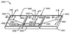
도 22 는 5개의 구성가능한 패널을 갖는 전자 디바이스 (2201) 의 특정한 예시적인 실시형태를 도시한다. 전자 디바이스 (2201) 는 완전하게 펼쳐진 구성 (2200) 에서 제 1 패널 (2202), 제 2 패널 (2204), 제 3 패널 (2206), 제 4 패널 (2208), 및 제 5 패널 (2210) 을 갖는다. 특정한 실시형태에서, 패널들 (2202-2210) 각각은 각각의 디스플레이 표면들 (2222, 2224, 2226, 2228) 을 포함할 수도 있어서, 완전하게 펼쳐진 구성 (2200) 에서, 유효 스크린 면적은 패널들 (2202-2210) 모두의 디스플레이 표면들에 의해 형성될 수도 있다. 특정한 실시형태에서, 전자 디바이스 (2201) 는 도 1 내지 도 7 의 전자 디바이스 (101), 도 8 의 전자 디바이스 (800), 도 9 내지 도 14 의 전자 디바이스 (900), 도 15 내지 도 17 의 전자 디바이스 (1501), 도 18 내지 도 20 의 전자 디바이스 (1801), 도 21 의 전자 디바이스 (2100), 또는 이들의 임의의 조합의 5개 패널 실시형태이다.22 shows a specific exemplary embodiment of an
도 23 은 과도 구성 (2300) 의 도 22 의 전자 디바이스 (2201) 의 특정한 실시형태를 도시한다. 제 1 패널 (2202) 은 도 22 에 도시된 완전하게 펼쳐진 위치로부터 각 패널 (2202 및 2204) 의 이면이 다른 패널의 이면에 근접한 위치로 제 1 패널 (2202) 및 제 2 패널 (2204) 이 회전할 수 있게 하도록 제 2 패널 (2204) 에 커플링된다. 유사하게는, 제 2 패널 (2204) 및 제 3 패널 (2206) 은 적어도 완전하게 펼쳐진 위치로부터 패널 (2206) 의 디스플레이 표면 (2226) 에 근접한 패널 (2204) 의 디스플레이 표면 (2224) 을 갖는 완전하게 접힌 위치로 위치가능하도록 회전가능하게 커플링된다. 패널 (2206) 및 패널 (2208) 은 적어도 완전하게 펼쳐진 위치로부터 패널 (2208) 의 이면에 근접한 패널 (2206) 의 이면을 갖는 완전하게 접힌 위치로 위치되도록 회전가능하게 커플링된다. 패널 (2208 및 2210) 은 적어도 완전하게 펼쳐진 위치로부터, 패널 (2208) 의 디스플레이 표면 (2228) 이 패널 (2210) 의 디스플레이 표면 (2230) 에 근접한 완전하게 접힌 위치로 위치가능하도록 회전가능하게 커플링된다. 특정한 실시형태에서, 도 22 및 도 23 에 도시된 전자 디바이스 (2201) 는 일반적으로 도 1 내지 도 21 에 도시된 전자 디바이스들 (101, 800, 900, 1501, 1801, 또는 2100) 과 유사할 수도 있고, 이전에 개시된 실시형태들의 하나 이상의 구성, 동작, 센서, 힌지, 또는 다른 특징을 포함할 수도 있다. 임의의 수의 패널이 본 개시물의 범위내에 있고 접음 구성의 변경에 기초하여 그래픽 디스플레이를 자동으로 조절하는 휴대 전자 디바이스에 포함될 수도 있다는 것을 이해해야 한다.Fig. 23 shows a specific embodiment of the
도 24 는 분리된 구성 (2400) 에서 3개의 분리가능한 패널을 갖는 전자 디바이스 (2401) 의 특정한 예시적인 실시형태를 도시한다. 제 1 패널 (2402) 은 제 1 패널 (2402) 이 제 2 패널 (2404) 의 제 2 커플링 메카니즘 (2412) 을 통해 제 2 패널 (2404) 에 커플링할 수 있게 하는 커플링 메카니즘 (2410) 을 포함한다. 커플링 메카니즘 (2410 및 2412) 은 제 1 패널 (2402) 과 제 2 패널 (2404) 사이에 기계적 및 전자 커플링을 제공하도록 구성될 수도 있다. 유사하게, 제 2 패널 (2404) 은 제 3 패널 (2406) 의 제 4 커플링 메카니즘 (2416) 에 기계적 및 전자 커플링을 제공하도록 구성된 제 3 커플링 메카니즘 (2414) 을 포함한다. 특정한 실시형태에서, 전자 디바이스 (2401) 는 도 1 내지 도 7 의 전자 디바이스 (101), 도 8 의 전자 디바이스 (800), 도 9 내지 도 14 의 전자 디바이스 (900), 도 15 내지 도 17 의 전자 디바이스 (1501), 도 18 내지 도 20 의 전자 디바이스 (1801), 도 21 의 전자 디바이스 (2100), 도 22 및 도 23 의 전자 디바이스 (2201), 또는 이들의 임의의 조합의 분리가능한 패널 실시형태이다.24 illustrates a particular exemplary embodiment of an
도 25 는 완전하게 부착된 구성 (2500) 의 도 24 의 전자 디바이스 (2401) 를 도시한다. 제 1 패널 (2402) 은 제 3 패널 (2406) 에 고정적으로 커플링되는 제 2 패널 (2404) 에 고정적으로 커플링된다. 패널들 (2402 내지 2406) 은 완전하게 펼쳐진 구성에 있다. 특정한 실시형태에서, 도 24 에 도시된 커플링 메카니즘 (2410 내지 2416) 은 패널들 (2402, 2404, 2406) 을 고정적으로 커플링할 수도 있어서, 패널들 (2402-2406) 사이에서 가능한 회전 이동은 거의 없다. 그러나, 다른 실시형태들에서, 커플링 메카니즘 (2410-2416) 은 도 1 내지 도 23 에 관하여 설명한 바와 같은 기능을 인에이블하기 위해, 패널들 (2402-2406) 중 하나 이상의 서로에 대한 회전 모션을 제공하거나 인에이블할 수도 있다.Fig. 25 shows the
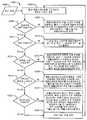
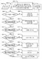
도 26 은 멀티-패널 전자 디바이스에서 소프트웨어 상태를 변경하는 방법의 예시적인 실시형태의 플로우차트이고, 일반적으로 2600 으로 표시된다. 특정한 실시형태에서, 이 방법 (2600) 은 도 1 내지 도 7 의 전자 디바이스 (101), 도 8 의 전자 디바이스 (800), 도 9 내지 도 14 의 전자 디바이스 (900), 도 15 내지 도 17 의 전자 디바이스 (1501), 도 18 내지 도 20 의 전자 디바이스 (1801), 도 21 의 전자 디바이스 (2100), 도 22 및 도 23 의 전자 디바이스 (2201), 도 24 및 도 25 의 전자 디바이스 (2401), 또는 이들의 임의의 조합에서 수행될 수도 있다.26 is a flowchart of an exemplary embodiment of a method for changing software state in a multi-panel electronic device, generally designated 2600. [ In a particular embodiment, the
특정한 실시형태에서, 전자 디바이스는 접힌 모드, 완전하게 접히지 않은 모드, 서밍 모드, 비디오 회의 모드, 및 여행용 시계 모드를 포함하는 널리 정의된 하드웨어 구성을 포함할 수도 있다. 각 패널 또는 패널들 사이의 폴드에서의 센서가 패널 또는 힌지 위치에서의 변경을 검출하고 보고할 수도 있다. 패널 또는 힌지 위치는 예를 들어, 대략 -180도 내지 대략 180도 사이의 범위내에서 폴드의 정도로 보고될 수도 있다. 도 18 내지 도 20 에 도시된 내부 센서 (1834) 와 같은 중간 패널에서의 하나 이상의 센서가 배향 변경을 검출하고 보고할 수도 있다. 소프트웨어 제어기가 센서 입력을 수집하고 분석할 수도 있고, 이 센서 입력에 응답하여 하나 이상의 액션을 취하는 것을 결정할 수 있다. 예를 들어, 소프트웨어 제어기는 애플리케이션 윈도우 또는 사용자 인터페이스 엘리먼트와 같은 애플리케이션의 크기의 변경을 개시할 수도 있고, 애플리케이션의 배향의 변경을 개시할 수도 있고, 애플리케이션의 자동-론치 (auto-launch) 를 개시할 수도 있고, 애플리케이션의 자동-엑시트 (auto-exit), 애플리케이션의 상태 변경을 개시할 수도 있고, 또는 액션들의 조합일 수도 있다.In a particular embodiment, the electronic device may include a well-defined hardware configuration including a folded mode, a non-collapsed mode, a summation mode, a video conferencing mode, and a travel clock mode. Sensors at each panel or folds between panels may detect and report changes in panel or hinge position. The panel or hinge position may be reported, for example, to a degree of fold within a range between approximately -180 degrees and approximately 180 degrees. One or more sensors in an intermediate panel, such as the
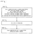
도 26 에 예시된 바와 같이, 전자 디바이스는 2602 에서 정의된 소프트웨어 상태를 갖는다. 예를 들어, 정의된 소프트웨어 상태는 애플리케이션이 구동 또는 대기중인지, 애플리케이션이 키보드 입력과 같은 사용자 입력을 수신하는지, 하나 이상의 애플리케이션 윈도우 크기, 위치, 배향, 및 애플리케이션에 대해 제공된 사용자 인터페이스의 타입과 같은 하나 이상의 파라미터를 나타낼 수도 있다. 정의된 소프트웨어 상태 (2602) 는 애플리케이션에 대해 이용가능한 다수의 패널 및 디스플레이 모드를 나타낼 수도 있다. 예를 들어, 디바이스는 접힌 구성에 있을 수도 있으며, 소프트웨어 제어기는 하나의 패널 세로 모드에서 애플리케이션을 론치할 수도 있다. 애플리케이션은 이용가능한 수의 패널 및 디스플레이 모드에 응답하고 사용자 경험을 개선하도록 하나 이상의 소정의 상태를 정의하거나 포함할 수도 있다.As illustrated in FIG. 26, the electronic device has a software state defined at 2602. For example, the defined software state may be determined based on whether the application is running or waiting, whether the application receives user input such as keyboard input, one or more application window sizes, locations, orientations, and type of user interface provided for the application The above parameters may also be indicated. Defined
2606 에서, 센서 입력 (2604) 이 수신되고, 패널 위치가 분석된다. 특정한 실시형태에서, 센서 입력 (2604) 은 힌지 위치, 배향, 또는 이동 중 하나 이상에서의 변경을 나타낼 수도 있다. 예를 들어, 힌지 위치에서의 변경은 도 15 내지 도 17 의 센서 (1512-1516) 또는 도 18 내지 도 20 의 센서 (1812 및 1822) 와 같은 힌지 센서에 의해 검출될 수도 있고, 배향 또는 이동에서의 변경은 도 15 내지 도 17 의 내부 센서 (1532-1536) 또는 도 18 내지 도 20 의 내부 센서 (1834) 와 같은 하나 이상의 내부 센서에 의해 검출될 수도 있다. 또한, 힌지 위치에서의 변경은 예를 들어, 인접 패널에 커플링된 경사계에 의해 검출되는 인접 패널의 상대적 배향에서의 변경을 통해 힌지 센서 이외의 센서에 의해 간접적으로 검출될 수 있다.At 2606, the
판정 2608 로 이동하여, 전자 디바이스가 정의된 하드웨어 상태에 있는지의 결정이 이루어진다. 전자 디바이스가 정의된 하드웨어 상태에 있지 않으면, 프로세싱은 2602 로 복귀한다. 예를 들어, 결정된 하드웨어 구성이 소정의 하드웨어 구성이 아니면, 소프트웨어 제어기는, 디바이스가 공지된 상태로의 트랜지션에 있다는 것을 가정할 수도 있고, 추가의 센서의 입력을 대기할 수도 있다.
2608 에서, 전자 디바이스가 정의된 하드웨어 상태에 있는 것으로 결정되면, 전자 디바이스는 2610 에서 새로운 소프트웨어 상태로 진입한다. 예를 들어, 전자 디바이스가 완전하게 접히지 않은 하드웨어 구성에 있는 것으로 결정되면, 소프트웨어 제어기는 3개 패널 가로형 모드 또는 3개 패널 세로형 모드와 같은 새로운 레이아웃 요건으로 애플리케이션을 재구성할 수도 있다.At 2608, if it is determined that the electronic device is in the defined hardware state, the electronic device enters the new software state at 2610. [ For example, if the electronic device is determined to be in a hardware configuration that is not fully collapsed, the software controller may reconfigure the application with new layout requirements, such as three-panel landscape mode or three-panel landscape mode.
특정한 실시형태에서, 소프트웨어 제어기는 회로 또는 다른 하드웨어, 펌웨어, 도 8 의 프로세서 (810) 와 같은 프로그램 명령들을 실행하는 하나 이상의 프로세서, 범용 프로세서 또는 전용 프로세서, 또는 이들의 임의의 조합에 의해 구현될 수도 있다. 특정한 실시형태에서, 도 8 의 소프트웨어 (834) 와 같은 애플리케이션은 동작의 다중의 소정의 상태를 지원하도록 기록될 수도 있으며, 특정한 하드웨어 상태 또는 상태의 변경을 나타내는 인터럽트 또는 세마포어 (semaphore) 와 같은 제어 신호에 응답할 수도 있다. 특정한 실시형태에서, 소프트웨어는 하드웨어 구성을 문의하고 소프트웨어 상태를 셀프-조절하는데 책임이 있다. 다른 실시형태에서, 소프트웨어는 소프트웨어 제어기로부터 하드웨어 상태 변경 메시지를 수신하기 위해 인터페이스를 지원하는데 책임이 있다.In a particular embodiment, the software controller may be implemented by circuitry or other hardware, firmware, one or more processors, general purpose processors, or special purpose processors that execute program instructions, such as
도 27 내지 도 31 은 전자 디바이스 (2701) 의 전용 하드웨어 구성에 응답하는 키보드를 자동으로 구성하는 특정한 실시형태를 도시한다. 특정한 실시형태에서, 전자 디바이스 (2701) 는 도 1 내지 도 7 의 전자 디바이스 (101), 도 8 의 전자 디바이스 (800), 도 9 내지 도 14 의 전자 디바이스 (900) 의 3개 패널 버전, 도 15 내지 도 17 의 전자 디바이스 (1501), 도 18 내지 도 20 의 전자 디바이스 (1801), 도 21 의 전자 디바이스 (2100), 도 22 및 도 23 의 전자 디바이스 (2201), 도 24 및 도 25 의 전자 디바이스 (2401), 또는 이들의 임의의 조합이다. 특정한 실시형태에서, 전자 디바이스 (2701) 는 도 26 의 방법 (2600) 에 따라 동작하도록 구성된다.Figs. 27-31 illustrate specific embodiments for automatically configuring a keyboard in response to a dedicated hardware configuration of the
도 27 은 완전하게 접힌 구성 (2700) 의 전자 디바이스 (2701) 를 도시한다. 완전하게 접힌 구성 (2700) 의 전자 디바이스 (2701) 는 디스플레이 윈도우 (2704) 및 키보드 영역 (2702) 을 나타내는 노출된 단일 패널 디스플레이 표면을 갖는다. 특정한 실시형태에서, 키보드 영역 (2702) 은 디스플레이 윈도우를 또한 포함하는 디스플레이 표면의 일부로서 디스플레이된 이미지이고, 터치 스크린 표면에서 검출되는 바와 같은 키 누름을 통해 작동될 수도 있다. 예시된 바와 같이, 디스플레이 윈도우 (2704) 및 키보드 영역 (2702) 을 포함하는 이미지는 단일의 노출된 디스플레이 표면상에 세로형 배향으로 디스플레이된다. 다른 실시형태에서, 전자 디바이스 (2701) 는 디스플레이 윈도우 및 키보드 영역을 포함하는 이미지를 가로형 배향으로 디스플레이하도록 구성될 수도 있다. 전자 디바이스 (2701) 는 전자 디바이스 (2701) 의 검출된 배향에 기초하여 세로형 배향 또는 가로형 배향으로 키보드 영역을 선택적으로 디스플레이하기 위해 하나 이상의 센서에 응답할 수도 있다.Fig. 27 shows the
도 28 은 서밍 구성 (2800) 의 도 27 의 전자 디바이스 (2701) 를 도시한다. 서밍 구성 (2800) 에서, 하부 패널은 도 27 에 도시된 작은 키보드 영역 (2702) 보다 큰 키보드 영역 (2802) 을 디스플레이하는 디스플레이 표면을 갖는다. 중간 패널의 제 1 디스플레이 표면 (2804), 및 상부 패널의 제 2 디스플레이 표면 (2806) 은 2개의 개별 디스플레이 윈도우를 형성할 수도 있거나, 2개 패널 유효 스크린을 형성하기 위해 결합될 수도 있다. 도 27 의 키보드 영역 (2702) 보다 큰 키보드 영역 (2802) 은 키보드 영역 (2802) 을 나타내는 디스플레이 표면에서 터치 스크린을 통해 유효 데이터 입력을 더 쉽게 사용하고 이동시킬 수 있게 할 수도 있다.Fig. 28 shows the
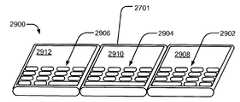
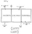
도 29 는 완전하게 펼쳐진 구성 (2900) 의 도 27 의 전자 디바이스 (2701) 를 예시한다. 완전하게 펼쳐진 구성 (2900) 에서, 키보드는 유효 디스플레이 스크린, 3개 패널 폭 및 하나의 패널 높이를 형성하는 모든 3개의 패널을 가로질러 연장되는 것으로서 예시된다. 유효 스크린을 포함하는 패널들 각각이 디스플레이된 가로형 이미지의 각각의 부분을 세로형 구성에서 디스플레이하지만, 가로형 모드에서의 유효 디스플레이 스크린은 높이 보다는 폭이 넓다. 키보드 (2902) 의 최우측 부분은 최우측 패널에서 디스플레이 영역의 최우측 부분 (2908) 아래에 디스플레이된다. 중앙 패널은 디스플레이 영역의 중앙 부분 (2910) 아래의 키보드의 중앙 부분 (2904) 을 디스플레이한다. 최좌측 패널은 디스플레이 영역의 최좌측 부분 (2912) 아래에 키보드의 최좌측 부분 (2906) 을 디스플레이한다.Fig. 29 illustrates the
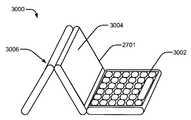
도 30 은 여행용 시계 (3000) 의 도 27 의 전자 디바이스 (2701) 를 도시한다. 제 1 수평 패널은 터치 스크린 표면에 의해 인식되는 터치를 통해 작동될 수도 있는 키보드 영역 (3002) 을 디스플레이한다. 중심 패널의 제 2 디스플레이 표면 (3004) 은 애플리케이션 윈도우, 아이콘, 다른 제어, 뿐만 아니라 시계 표시의 시각적 디스플레이를 위해 사용될 수도 있다. 제 3 디스플레이 표면 (3006) 은 파워 다운되거나, 야간 조명, 하나 이상의 장식용 설계의 디스플레이, 사용자 특정 디스플레이, 또는 이들의 임의의 조합과 같은 다른 기능을 수행하는 디스플레이 영역을 가질 수도 있다.Fig. 30 shows the
도 31 은 비디오 회의 구성 (3100) 의 도 27 의 디바이스 (2701) 를 예시한다. 카메라 (3104) 가 접힌 구성으로 도시된 최좌측 패널의 이면상에 예시되어 있다. 최좌측 패널의 이면은 추가 디스플레이 (3102) 와 같은 추가 사용자 인터페이스 메카니즘을 포함할 수도 있다. 또한, 최우측 패널은 디스플레이 표면의 하부 부분에서 키보드 영역 (3106), 및 비디오 회의 콜의 참가자의 이미지를 나타낼 수도 있고, 키보드 영역 (3106) 위에 위치되는 디스플레이 영역 (3108) 으르 제공하도록 분할될 수도 있다. 일반적으로, 전자 디바이스 (2701) 는 예를 들어, 패널 내부, 힌지 내부의 하나 이상의 센서, 또는 다른 센서를 통해 디바이스 (2701) 의 구성을 인식하도록 프로그래밍가능할 수도 있고, 도 27 내지 도 31 에 예시된 바와 같이, 하나 이상의 적절한 디스플레이 표면의 적절한 부분에서 키보드의 디스플레이를 자동으로 재구성할 수도 있다. 디스플레이 패널, 및 특히 키보드의 재구성, 재디스플레이, 및 재배향은 사용자로부터 요구되거나 사용자로부터 검출된 어떠한 다른 입력없이, 사용자 구성, 접음, 하드웨어 조절, 경사, 배향, 가속도, 또는 이들의 임의의 조합에 자동으로 응답하여 수행될 수도 있다.31 illustrates
도 32 내지 도 37 은 전자 디바이스 (3201) 의 구성에 응답하고, 개방 및 닫힘 애플리케이션에 대한 사용자 입력에 더 응답하는 아이콘 제어 패널을 갖는 전자 디바이스 (3201) 를 예시한다. 특정한 실시형태에서, 전자 디바이스 (3201) 는 도 1 내지 도 7 의 전자 디바이스 (101), 도 8 의 전자 디바이스 (800), 도 9 내지 도 14 의 전자 디바이스 (900) 의 3개 패널 버전, 도 15 내지 도 17 의 전자 디바이스 (1501), 도 18 내지 도 20 의 전자 디바이스 (1801), 도 21 의 전자 디바이스 (2100), 도 22 및 도 23 의 전자 디바이스 (2201), 도 24 및 도 25 의 전자 디바이스 (2401), 도 27 내지 도 31 의 전자 디바이스 (2701), 또는 이들의 임의의 조합이다. 특정한 실시형태에서, 전자 디바이스 (3201) 는 도 26 의 방법 (2600) 에 따라 동작하도록 구성된다.32-37 illustrate an
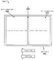
도 32 는 완전하게 접힌 구성 (3200) 의 전자 디바이스 (3201) 를 도시한다. 최좌측 패널의 디스플레이 표면은 예를 들어, 전력 표시자, 신호 강도 표시자, 알람 신호, 디지털 네트워크 대역폭 표시, 표시, 또는 이들의 임의의 조합을 포함하는 무선 전화 표시와 같은 하나 이상의 제어 또는 다른 표시 (3204) 를 예시한다. 상위 디스플레이 표면은 대표적인 애플리케이션 아이콘 (3206) 과 같은 다중의 애플리케이션 아이콘을 더 포함한다. 애플리케이션 아이콘은 디스플레이 표면에서의 터치 감지형 표면을 통한 사용자 입력에 응답할 수도 있다. 전자 디바이스 (3201) 는 전화 전기통신에 유용할 수도 있으며, 마이크로폰 (3240), 스피커 (3242), 전자 디바이스 (3201) 의 하나 이상의 기능을 인에이블하기 위한 다른 하드웨어 엘리먼트, 또는 이들의 임의의 조합을 포함할 수도 있다.32 shows the
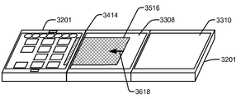
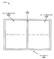
도 33 은 완전하게 펼쳐진 구성 (3300) 의 도 32 의 전자 디바이스 (3201) 를 도시한다. 디바이스 (3201) 가 도 32 의 완전하게 접힌 구성 (3200) 으로부터 도 33 의 완전하게 펼쳐진 구성 (3300) 으로 펼쳐질 때, 중심 패널의 디스플레이 스크린 (3308) 및 최우측 패널의 디스플레이 스크린 (3310) 은 노출되어 사용자가 볼 수 있다. 디스플레이 스크린 (3308 및 3310) 은 데스크탑 영역을 나타낼 수도 있지만, 최좌측 패널은 대표적인 애플리케이션 아이콘 (3206) 을 포함하는 아이콘 패널을 계속 나타낼 수도 있다.Fig. 33 shows the
도 34 는 사용자 입력에 응답하여 최좌측 디스플레이 표면과 중심 디스플레이 표면 (3308) 사이의 갭 (3414) 을 향한 대표적인 애플리케이션 아이콘 (3206) 의 이동을 도시한다. 예를 들어, 사용자 입력은 갭 (3414) 을 향한 대표적인 애플리케이션 아이콘 (3206) 의 이동을 나타내는 드래깅 동작일 수도 있고, 애플리케이션 (3206) 의 이동의 속도 및 방향을 통해, 대표적인 애플리케이션 아이콘 (3206) 이 갭 (3414) 을 가로질러 이동된다는 것을 표시할 수도 있다. 대표적인 애플리케이션 아이콘 (3206) 의 이동이 화살표 (3412) 로서 예시되어 있고, 여기서, 이동 속도는 화살표 (3412) 의 길이로서 예시되고, 이동 방향은 화살표 (3412) 의 방향으로서 표시된다. 애플리케이션 아이콘 (3206) 의 이동의 속도 및 방향은, 사용자 입력이 터치스크린에서 드래깅 동작으로서 수신될 때와 같은 사용자 입력과 관련된 사용자의 의도를 예측하기 위해 사용될 수도 있다. 예를 들어, 애플리케이션 아이콘 (3206) 의 이동의 속도 및 방향은, 사용자 입력이 갭 (3414) 에 도달하기 이전에 종료하더라도, 사용자 입력이 갭 (3414) 을 가로질러 애플리케이션 아이콘 (3206) 을 이동시키려 의도된다는 것을 예측하기 위해 사용될 수도 있다. 특정한 실시형태에서, 하나 이상의 물리 법칙이 운동량 및 마찰과 같은 사용자 인터페이스 엘리먼트에 대해 시뮬레이션될 수도 있어서, 사용자는 사용자 인터페이스 엘리먼트의 모션을 개시할 수도 있고, 사용자 인터페이스 엘리먼트는 인터페이스의 시뮬레이션된 물리학에 따라 그것의 모션을 계속할 수도 있다. 예를 들어, 드래깅 동작에 의한 모션으로 설정된 후 해제된 인터페이스 엘리먼트는, 사용자에게 예측가능하고 사용자에 의해 직관적으로 또는 자연적으로 인지될 수도 있는 방식으로 속도가 느려지고 정지될 수도 있다.Figure 34 illustrates the movement of an
도 34 에 예시되어 있는 바와 같이, 사용자 입력에 의해 제공된 이동의 속도 및 방향이 갭 (3414) 을 크로스할 아이콘 (3206) 에 대한 명령을 표시할 때, 아이콘 (3206) 의 적어도 일부는 중심 디스플레이 패널 (3308) 에 디스플레이될 수도 있지만, 아이콘 (3206) 의 나머지 부분은 최좌측 디스플레이 패널에 디스플레이될 수도 있다. 이러한 방식으로, 사용자는 갭 (3414) 을 가로지르는 연속 모션을 갖는 대표적인 애플리케이션 아이콘 (3206) 의 시각적 레퍼런스를 유지할 수도 있다. 특정한 실시형태에서, 아이콘 (3206) 이 상대적으로 느리게 이동할 때 도시된 바와 같이, 대표적인 애플리케이션 아이콘 (3206) 은 갭 (3414) 을 가로질러 이동될 수도 있고, 중심 디스플레이 영역 (3308) 에 위치될 수도 있다. 그러나, 애플리케이션 아이콘 (3206) 이 갭 (3414) 을 가로질러 충분한 속도로 이동될 때, 전자 디바이스 (3201) 는 갭 (3414) 을 가로지른 대표적인 애플리케이션 아이콘 (3206) 의 이동을 표시하는 사용자 입력을, 대표적인 애플리케이션 아이콘 (3206) 과 관련된 애플리케이션에 대한 론치 명령으로서 해석할 수도 있다.34, when the velocity and direction of movement provided by the user input indicates a command for an
도 35 에 예시된 바와 같이, 특정할 실시형태에서, 도 32 내지 도 34 의 애플리케이션 아이콘 (3206) 이 충분한 속도로 갭 (3414) 을 가로질러 풀 (pull) 될 때, 예를 들어, 중심 디스플레이 영역 (3308) 에서 애플리케이션 윈도우 (3516) 을 개방함으로써 애플리케이션 아이콘 (3206) 과 관련되는 애플리케이션이 론치된다. 다른 실시형태에서, 애플리케이션 윈도우 (3516) 는 2개 패널 유효 디스플레이 스크린으로서 동작하도록 구성될 수도 있는 중심 디스플레이 표면 (3308) 및 최우측 디스플레이 표면 (3310) 양자를 커버하기 위해 확장할 수도 있다.As illustrated in Figure 35, in a particular embodiment, when the
도 36 에 예시되어 있는 바와 같이, 특정한 실시형태에서, 사용자는, 애플리케이션 윈도우 (3516) 에게 갭 (3414) 을 향해 화살표 (3618) 에 의해 예시된 이동을 갖도록 지시하는 사용자 입력을 제공함으로써 전자 디바이스에게 애플리케이션 윈도우 (3516) 를 폐쇄하는 것을 명령할 수도 있다. 애플리케이션 윈도우 (3516) 는 갭 (3414) 을 향해 이동하는 것으로서 디스플레이될 수도 있고, 애플리케이션 윈도우 (3516) 가 갭 (3414) 을 적어도 부분적으로 가로지르는 것처럼 보이도록 시각적 연속성을 전자 디바이스 (3201) 의 사용자에게 제공하기 위해 최좌측 패널의 제 1 디스플레이 표면에 디스플레이된 적어도 일부를 갖는 것으로서 또한 디스플레이될 수도 있다. 특정한 실시형태에서, 갭 (3414) 을 가로지르는 애플리케이션 윈도우 (3516) 의 특정한 모션이 발생하였거나 발생할 때와 같은, 애플리케이션 윈도우 (3516) 가 갭 (3414) 을 향해 충분한 거리를 이동하도록 사용자 입력에 의해 명령될 때, 전자 디바이스 (3201) 는 애플리케이션 윈도우 (3516) 에 디스플레이된 애플리케이션을 폐쇄하고, 애플리케이션 및 애플리케이션 윈도우 (3516) 를 폐쇄하며, 도 37 에 도시된 바와 같이 대표적인 애플리케이션 아이콘 (3206) 을 최좌측 표면 패널의 원래의 위치로 복귀시키기 위한 커맨드로서 사용자 입력을 해석할 수도 있다.36, in a particular embodiment, the user is presented to the electronic device by providing a user input that directs the
도 32 내지 도 37 은 사용자 인터페이스와의 인터페이스 또는 상호작용을 트리거하기 위해 멀티-스크린 전자 디바이스상의 터치 스크린들 사이의 갭을 사용하는 상호작용의 방법을 예시한다. 갭의 위치와 크기를 인지함으로써, 애플리케이션 또는 소프트웨어는 상호작용의 다른 방법으로서 갭을 사용할 수 있다. 일 예로서, 브라우저가 나머지 스크린상에 디스플레이하기 위해 하나의 스크린으로부터 론치될 수 있다. 제 1 스크린은 도 33 의 애플리케이션 아이콘 (3206) 과 같은 브라우저에 대한 하나를 포함하는 애플리케이션 아이콘을 포함할 수 있다. 사용자는 그들의 손가락을 브라우저에 대한 아이콘상에 위치시킬 수 있고, 그 후, 도 34 의 갭 (3414) 과 같은 스크린 갭의 방향으로 아이콘을 드래그할 수도 있다. 사용자가 갭에 도달할 때, 상호작용은 개시되고 시각화될 수 있어서, 나머지 스크린에서 개방하는 브라우저를 나타낸다. 이러한 트리거의 리버스 사용은 발신 스크린으로 역으로 폐쇄 또는 하이드 피처를 개시하는 소정의 갭을 가로질러, 도 35 의 애플리케이션 윈도우 (3516) 와 같은 개방 애플리케이션의 몇몇 부분을 드래그하는 것을 포함할 수 있다.32-37 illustrate a method of interaction using a gap between touch screens on a multi-screen electronic device to trigger an interface or interaction with the user interface. By recognizing the position and size of the gap, the application or software can use the gap as an alternative method of interaction. As an example, a browser may be launched from one screen for display on the remaining screens. The first screen may include an application icon that includes one for the browser, such as the
도 34 및 도 36 에 예시되어 있는 바와 같이, 사용자가 다중의 스크린을 가로질러 드래그하는 동안, 갭을 가로지른 방향 및 위치 모두를 나타내기 위해 시각적 큐가 사용자 인터페이스 엘리먼트의 순방향측상에서 사용될 수도 있다. 드래그될 때, (아이콘 또는 애플리케이션 윈도우와 같은) 사용자 인터페이스 엘리먼트는 순방향에서 다수의 픽셀을 시프트할 수도 있어서, 이것은 여전히 사용자에게 가시적이고, 방향을 큐한다. 예를 들어, 애플리케이션을 자동 론치하거나 사용자 인터페이스 엘리먼트를 다른 스크린으로 이동시키기 위해 다중의 스크린들 사이의 갭을 가로질러 드래그할 때, 사용자 인터페이스 엘리먼트는 스크린을 가로질러 이동시키기 위한 방향 및 능력을 모두 나타내기 위해 측정된 갭과 동일한 거리를 순방향 시프트할 수도 있다. 갭을 크로스하는 방향, 위치, 및 능력을 나타냄으로써, 전자 디바이스 (3201) 는 사용자 인터페이스 엘리먼트를 드래그하면서 연속 큐를 사용자에게 제공할 수도 있다. 그 결과 사용자 에러가 감소될 수도 있으며, 전자 디바이스 (3201) 의 사용성이 개선될 수도 있다.As illustrated in FIGS. 34 and 36, while the user drags across multiple screens, a visual cue may be used on the forward side of the user interface element to indicate both the direction and the position across the gap. When dragged, a user interface element (such as an icon or application window) may shift a number of pixels in the forward direction, which is still visible to the user and queues the direction. For example, when dragging across a gap between multiple screens to automatically launch an application or move a user interface element to another screen, the user interface element displays both direction and ability to move across the screen May be forward-shifted by the same distance as the gap measured to emerge. By indicating the direction, position, and ability to cross the gap, the
도 38 을 참조하면, 가속도계 및 경사계를 갖는 전자 디바이스 (3801) 의 특정한 예시적인 실시형태가 도시되어 있고 일반적으로 3800 로 표시된다. 특정한 실시형태에서, 전자 디바이스 (3801) 는 도 1 내지 도 7 의 전자 디바이스 (101), 도 8 의 전자 디바이스 (800), 도 9 내지 도 14 의 전자 디바이스 (900) 의 3개 패널 버전, 도 15 내지 도 17 의 전자 디바이스 (1501), 도 18 내지 도 20 의 전자 디바이스 (1801), 도 21 의 전자 디바이스 (2100), 및 도 22 및 도 23 의 전자 디바이스 (2201), 도 24 및 도 25 의 전자 디바이스 (2401), 도 27 내지 도 31 의 전자 디바이스 (2701), 도 32 내지 도 37 의 전자 디바이스 (3201), 또는 이들의 임의의 조합이다. 특정한 실시형태에서, 전자 디바이스 (3801) 는 도 26 의 방법 (2600) 에 따라 동작하도록 구성된다.38, a specific exemplary embodiment of an
전자 디바이스 (3801) 는 제 1 디스플레이 표면 (3832) 을 갖는 제 1 패널 (3802), 제 2 디스플레이 표면 (3834) 을 갖는 제 2 패널 (3804), 및 제 3 디스플레이 표면 (3836) 을 갖는 제 3 패널 (3806) 을 포함한다. 3개의 디스플레이 표면 (3832 내지 3836) 은 모든 3개의 디스플레이 표면 (3832 내지 3836) 을 가로질러 확장하는 단일 디스플레이 스크린을 에뮬레이트하도록 제어된다. 제 1 패널 (3802) 은 제 2 패널 (3804) 의 제 1 에지에 회전가능하게 커플링되고, 제 3 패널 (3806) 은 제 2 패널 (3804) 의 제 2 에지에 회전가능하게 커플링된다. 경사계 (3810) 가 제 2 패널 (3804) 에 위치되고, 가속도계 (3820) 가 제 2 패널의 세로축 (3814) 으로부터 오프셋된다. 프로세서 (3830) 와 같은 제어기가 경사계 (3810) 및 가속도계 (3820) 에 커플링된다.The
경사계 (3810) 는 제 2 패널 (3804) 의 경사에서의 변화를 검출하도록 구성된다. 예를 들어, 경사계 (3810) 는 세로축 (3814) 주위의 세로 회전 방향 (3812) 에 의해 초래된 배향에서의 변화를 검출하도록 구성될 수도 있다. 가속도계 (3820) 는 가로형 배향으로부터 세로형 배향으로 제 2 패널 (3804) 의 면내 회전 방향 (3822) 을 검출하도록 구성될 수도 있다.The
특정한 실시형태에서, 프로세서 (3830) 는 그래픽 사용자 인터페이스를 갖는 적어도 하나의 소프트웨어 애플리케이션을 실행하도록 구성될 수도 있다. 프로세서 (3830) 는, 제 1 패널 (3832), 제 2 패널 (3834), 및 제 3 패널 (3836) 이 적어도 하나의 소정의 접음 구성에 있고, 제 2 패널 (3834) 의 경사에서의 변화가 제 2 패널 (3834) 의 회전 동안 임계값을 초과하지 않을 때 이미지의 가로형 디스플레이로부터 이미지의 세로형 디스플레이로, 제 1 디스플레이 표면 (3832), 제 2 디스플레이 표면 (3834), 제 3 디스플레이 표면 (3836), 또는 이들의 임의의 조합에 디스플레이된 이미지를 리드로잉 (redraw) 하기 위해 경사계 (3810) 및 가속도계 (3820) 에 응답한다. 예를 들어, 임계값은 5도 와 30 (또는 -5도 와 -30도) 사이의 범위의 각일 수도 있고, 대략 15도 (또는 -15도) 일 수도 있다.In a particular embodiment, the
예를 들어, 제어기는 검출된 가속도가 보행하고 디바이스 (3801) 를 운반하는 사람에 대해 검출될 것으로 예상되는 예상 가속도 보다 빠른지, 및 경사계 (3810) 가 경사에서 변화없음 (또는 임계 변화 보다 작음) 을 검출하였는지를 계산하기 위해 구성될 수도 있다. 제어기는 디바이스 (3801) 가 컨텐츠 주위에서 턴할 때 그 자리에서 컨텐츠를 홀딩할 수도 있다. 디스플레이가 디스플레이의 원래의 위치에 비교하여 위치를 변경할 수도 있기 때문에, 제어기는 가속도가 중지될 때까지 컨텐츠를 연속적으로 리드로잉할 수도 있다. 예를 들어, 이것은 디바이스 (3801) 의 사용자가 디바이스 (3801) 를 데스크상에 두게 할 수 있고 디스플레이를 세로로부터 가로로 또는 그 사이의 임의의 위치로 스위칭하기 위해 디바이스 (3801) 를 시계방향 또는 반시계방향으로 스핀하게 할 수 있다.For example, the controller may determine that the detected acceleration is faster than the expected acceleration that is expected to be detected for the person walking and carrying the
도 39 내지 도 41 은, 디바이스 (3801) 가 가로 배향으로부터 세로 배향으로 회전될 때 도 38 의 전자 디바이스 (3801) 의 동작을 예시한다.Figs. 39 to 41 illustrate the operation of the
도 39 에서, 전자 디바이스 (3801) 는 가로 모드 (3900) 로 도시되고, 여기서, 웹 브라우저 애플리케이션 이미지가 모든 3개의 디스플레이 표면에 걸쳐 가로형 디스플레이로서 디스플레이된다. 디바이스 (3801) 는 중간 패널의 경사를 실질적으로 변화시키지 않고 도 40 에 도시된 과도 위치 (4000) 를 통해 도 41 에 도시된 프로파일 모드 위치 (4100) 로 반시계방향으로 회전될 수도 있다. 예를 들어, 디바이스 (3801) 는 테이블 또는 데스크와 같은 표면상에 편평하게 배치될 수도 있으며 회전될 수도 있다. 다른 예로서, 디바이스 (3801) 는 디바이스 (3801) 가 회전될 때, 수직 경사와 같은 실질적으로 일정한 경사에 홀딩될 수도 있다.39,
도 40 에 예시된 바와 같이, 디바이스 (3801) 가 면내 회전 방향 (3822) 에서는 회전하지만 세로 회전 방향 (3812) 에서는 현저하게 회전하지 않는다는 것을 나타내는 입력을 가속도계 (3820) 및 경사계 (3810) 로부터 프로세서 (3830) 가 수신할 때, 디스플레이 패널에 디스플레이된 이미지는 뷰어에 관하여 이미지의 배향을 유지하기 위해 계속 리드로잉될 수도 있다. 이러한 리드로잉은 디스플레이 표면이 기반 이미지에 대하여 윈도우로서 기능하는 사용자에게 외관을 제공할 수도 있고, 여기서, 윈도우는 회전하고 이미지는 정지를 유지한다. 도 41 은 도 39 의 가로형 구성으로부터 디바이스를 쿼터-턴 반시계방향으로 회전시킴으로써 획득되는 세로형 배향에서 전자 디바이스 (3801) 를 예시한다. 따라서, 사용자는 사용자가 컨텐츠의 뷰잉 배향으로 충족될 때까지 디바이스 (3801) 를 계속 회전시킬 수도 있다.An input indicating that the
특정한 실시형태에서, 게이밍 애플리케이션이 디바이스 (3801) 에 의해 실행될 수도 있어서, 사용자는 디바이스 (3801) 를 회전시킴으로써 제어 입력을 제공한다. 예를 들어, 드라이빙 애플리케이션이 펼쳐진 디스플레이 패널에 걸쳐 레이스트랙의 드라이버의 뷰를 디스플레이할 수도 있고, 사용자는 레이스트랙상에서 차량의 스티어링을 제어하기 위해 스티어링 휠로서 디바이스 (3801) 를 회전시킬 수도 있고, 여기서, 뷰는 디바이스와 회전되지 않고, 그 대신에, 사용자의 시각으로부터 실질적으로 정지 배향에서 유지된다. 또한, 특정한 환경하에서, 디바이스 (3801) 의 검출된 회전은 디스플레이의 연속 리드로잉에 부가하여 특정한 프로세스를 개시하기 위해 사용될 수도 있다. 예를 들어, 디바이스 (3801) 가 게이밍 애플리케이션을 실행할 때, 검출된 회전은 디바이스 (3801) 의 하나 이상의 진동 액추에이터 (미도시) 또는 다른 하드웨어 엘리먼트를 트리거할 수도 있다.In a particular embodiment, a gaming application may be executed by the
도 42 는 멀티 패널 전자 디바이스에서 소프트웨어 상태를 변경하는 방법 (4200) 의 제 2 예시적인 실시형태의 플로우차트이다. 특정한 실시형태에서, 이 방법 (4200) 은 도 1 내지 도 7 의 전자 디바이스 (101), 도 8 의 전자 디바이스 (800), 도 9 내지 도 14 의 전자 디바이스 (900), 도 15 내지 도 17 의 전자 디바이스 (1501), 도 18 내지 도 20 의 전자 디바이스 (1801), 도 21 의 전자 디바이스 (2100), 도 22 및 도 23 의 전자 디바이스 (2201), 도 24 및 도 25 의 전자 디바이스 (2401), 도 27 내지 도 31 의 전자 디바이스 (2701), 도 32 내지 도 37 의 전자 디바이스 (3201), 도 38 내지 도 41 의 전자 디바이스 (3801), 또는 이들의 임의의 조합에서 수행될 수도 있다.42 is a flowchart of a second exemplary embodiment of a
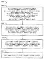
방법 (4200) 은 디바이스가 파워 온된 이후 및 사용자가 애플리케이션을 론치하기 이전과 같이 애플리케이션을 실행하는 사용자 인터페이스가 디스플레이되지 않을 때의 전자 디바이스의 디폴트 상태를 예시한다. 4204 에서, 센서 입력 (4202) 이 새로운 하드웨어 구성을 검출하기 위해 수신되어 사용된다. 예를 들어, 센서 입력 (4202) 은 하나 이상의 힌지 센서, 경사계, 가속도계, 하나 이상의 다른 센서, 또는 이들의 임의의 조합을 통해서와 같이 멀티 패널 디바이스의 하나 이상의 패널의 상대적 배향, 또는 배향에서의 변화를 나타낼 수도 있다.The
판정 4206 으로 이동하여, 4206 에서, 디바이스가 완전하게 접힌 구성에 있는지의 결정이 이루어진다. 디바이스가 완전하게 접힌 구성에 있는 것으로 결정되면, 4208 에서, 아이콘 패널이 활성 스크린상에 디스플레이될 수도 있고, 다른 스크린이 파워 다운될 수도 있다.Go to
디바이스가 완전하게 접힌 구성에 있지 않은 것으로 결정되면, 판정 4210 에서, 디바이스가 서밍 구성에 있는지의 결정이 이루어진다. 디바이스가 서밍 구성에 있는 것으로 결정되면, 4212 에서, 데스크탑 아이콘이 상부 2개의 뷰잉 스크린상에 디스플레이될 수도 있고, 키보드가 하부 스크린상에 디스플레이될 수도 있다.If it is determined that the device is not in a fully collapsed configuration, then at
디바이스가 서밍 구성에 있지 않은 것으로 결정되면, 판정 4214 에서, 디바이스가 여행용 시계 구성에 있는지의 결정이 이루어진다. 디바이스가 여행용 시계 구성에 있는 것으로 결정되면, 4216 에서, 시계가 중간 스크린에 디스플레이될 수도 있고, 시계 모드 제어가 수평 스크린에서 디스플레이될 수도 있으며, 백 스크린은 파워 다운될 수도 있다.If it is determined that the device is not in the summing configuration, then a determination is made at
디바이스가 여행용 시계 구성에 있지 않은 것으로 결정되면, 판정 4218 에서, 디바이스가 완전하게 펼쳐진 구성에 있는지의 결정이 이루어진다. 디바이스가 완전하게 펼쳐진 구성에 있는 것으로 결정되면, 4220 에서, 아이콘 패널이 최좌측 스크린에 디스플레이될 수도 있고, 다른 2개의 스크린은 애플리케이션을 위해 클리어로 남겨질 수도 있다.If it is determined that the device is not in the travel clock configuration, then at
디바이스가 완전하게 펼쳐진 구성에 있지 않은 것으로 결정되면, 판정 4222 에서, 디바이스가 비디오 회의 구성에 있는지의 결정이 이루어진다. 디바이스가 비디오 회의 구성에 있는 것으로 결정되면, 4224 에서, 비디오 회의 비디오가 활성 스크린의 상부 부분에 디스플레이될 수도 있고, 비디오 회의 모드 제어가 활성 스크린의 하부 부분에 디스플레이될 수도 있으며, 다른 스크린들은 파워 다운될 수도 있다.If it is determined that the device is not in a fully deployed configuration, then a determination is made at
디바이스가 비디오 회의 구성에 있지 않은 것으로 결정되면, 4226 에서, 디바이스가 과도 구성에 있는지의 결정이 이루어질 수도 있고, 디스플레이 패널에서 수행될 수도 있는 변경은 없고, 프로세싱은 4204 로 리턴할 수도 있다.If it is determined that the device is not in a video conferencing configuration, then at 4226, a determination may be made whether the device is in a transient configuration, no changes may be made to the display panel, and processing may return to 4204.
방법 (4200) 이 5개의 하드웨어 구성을 예시하지만, 다른 실시형태들에서는, 6개 이상 또는 5개 미만의 구성이 사용될 수도 있다. 예를 들어, 접음 스크린과 유사한 수직 구성은 전자 디바이스로 하여금, 보조 데스크탑 기구로서 사용하기 위해 무선 데이터 네트워크를 통해 수신된 스트리밍 실시간 뉴스, 주식 시세, 및 블로그 피드 (blog feed) 를 디스플레이하는 것을 자동으로 시작하게 하거나, 디바이스에 저장되거나 데이터 네트워크를 통해 수신된 플레이리스트를 플레이하는 것을 시작하기 위해 오디오 또는 비디오 파일 플레이어를 론치하게 하거나, 사용자 구성에 따라 다른 애플리케이션을 자동으로 론치하게 하거나, 이들의 임의의 조합을 하게 할 수도 있다. 또한, 커스텀 구성은 전자 디바이스로 프로그래밍될 수도 있고, 센서 입력 (4202) 이 수신될 때에 대해 테스트될 수도 있다.Although
도 43 은 멀티 패널 전자 디바이스에서 소프트웨어 상태를 변경하는 방법 (4300) 의 제 3 예시적인 실시형태의 플로우차트이다. 특정한 실시형태에서, 이 방법 (4300) 은 도 1 내지 도 7 의 전자 디바이스 (101), 도 8 의 전자 디바이스 (800), 도 9 내지 도 14 의 전자 디바이스 (900), 도 15 내지 도 17 의 전자 디바이스 (1501), 도 18 내지 도 20 의 전자 디바이스 (1801), 도 21 의 전자 디바이스 (2100), 도 22 및 도 23 의 전자 디바이스 (2201), 도 24 및 도 25 의 전자 디바이스 (2401), 도 27 내지 도 31 의 전자 디바이스 (2701), 도 32 내지 도 37 의 전자 디바이스 (3201), 도 38 내지 도 41 의 전자 디바이스 (3801), 또는 이들의 임의의 조합에서 수행될 수도 있다.43 is a flowchart of a third exemplary embodiment of a
방법 (4300) 은, 다중의 소프트웨어 상태를 지원하고, 전자 디바이스의 구성 변경에 응답하는 애플리케이션을 실행할 때 전자 디바이스의 디폴트 상태를 예시한다. 4304 에서, 활성 애플리케이션을 구동하는 동안, 센서 입력 (4302) 이 새로운 하드웨어 구성을 검출하기 위해 수신되고 사용된다. 예를 들어, 센서 입력 (4302) 은 하나 이상의 힌지 센서, 경사계, 가속도계, 하나 이상의 다른 센서, 또는 이들의 임의의 조합을 통해서와 같이 멀티 패널 디바이스의 하나 이상의 패널의 상대적 배향 또는 배향의 변화를 나타낼 수도 있다.The
판정 4306 으로 이동하여, 4306 에서, 디바이스가 완전하게 접힌 구성에 있는지의 결정이 이루어진다. 디바이스가 완전하게 접힌 구성에 있는 것으로 결정되는 경우에, 4308 에서, 애플리케이션이 단일 스크린 구성을 지원하면, 단일 스크린 모드에서의 애플리케이션의 애플리케이션 윈도우가 활성 스크린상에 디스플레이되고, 다른 스크린들은 파워 다운된다. 애플리케이션이 단일 스크린 모드를 지원하지 않으면, 애플리케이션은 활성 스크린에서 중지되고 디스플레이되지 않을 수도 있다.Go to
디바이스가 완전하게 접힌 구성에 있지 않은 것으로 결정되면, 판정 4310 에서, 디바이스가 서밍 구성에 있는지의 결정이 이루어진다. 디바이스가 서밍 구성에 있는 것으로 결정되면, 4312 에서, 애플리케이션 윈도우는 2-패널 유효 스크린에서 디스플레이될 수도 있고, 키보드가 하부 스크린에서 디스플레이될 수도 있다.If it is determined that the device is not in a fully collapsed configuration, then at
디바이스가 서밍 구성에 있지 않은 것으로 결정되면, 4314 에서, 디바이스가 여행용 시계 구성에 있는지의 결정이 이루어진다. 디바이스가 여행용 시계 구성에 있는 것으로 결정되는 경우에, 4316 에서, 애플리케이션이 여행용 시계 구성을 지원하면, 애플리케이션 인터페이스가 중간 스크린상에 시계 또는 수평 스크린상에 시계 모드 제어, 또는 양자로 디스플레이되고, 백 스크린이 파워 다운된다. 애플리케이션이 여행용 시계 구성을 지원하지 않으면, 애플리케이션은 정지되고 디스플레이되지 않을 수도 있다.If it is determined that the device is not in a summing configuration, then at 4314, a determination is made whether the device is in a travel clock configuration. If the device is determined to be in a travel clock configuration, then at 4316, if the application supports travel clock configuration, the application interface may be displayed on the intermediate screen in a clocked or horizontal mode, or both, This power is down. If the application does not support travel clock configuration, the application may be stopped and not displayed.
디바이스가 여행용 시계 구성에 있지 않은 것으로 결정되면, 판정 4318 에서, 디바이스가 완전하게 펼쳐진 구성에 있는지의 결정이 이루어진다. 디바이스가 완전하게 펼쳐진 구성에 있는 것으로 결정되는 경우에, 4320 에서, 애플리케이션이 완전하게 펼쳐진 구성을 지원하면, 애플리케이션 윈도우는 모든 3개의 스크린에 걸쳐 디스플레이될 수도 있다. 애플리케이션이 완전하게 펼쳐진 구성을 지원하지 않으면, 애플리케이션 윈도우는 하나 이상의 스크린상에서 디스플레이될 수도 있다.If it is determined that the device is not in the travel clock configuration, then at
디바이스가 완전하게 펼쳐진 구성에 있지 않은 것으로 결정되면, 판정 4322 에서, 디바이스가 비디오 회의 구성에 있는지의 결정이 이루어진다. 디바이스가 비디오 회의 구성에 있는 것으로 결정되는 경우에, 4324 에서, 애플리케이션이 비디오 회의 구성을 지원하면, 애플리케이션 인터페이스가 활성 스크린의 상부 부분에서 비디오 및/또는 활성 스크린의 하부 부분에서 비디오 회의 모드 제어로 디스플레이될 수도 있고, 다른 스크린은 파워 다운될 수도 있다. 애플리케이션이 비디오 회의 구성을 지원하지 않으면, 애플리케이션을 정지될 수도 있다.If it is determined that the device is not in a fully deployed configuration, then at
디바이스가 비디오 회의 구성에 있지 않은 것으로 결정되면, 4326 에서, 디바이스가 과도 구성에 있는지의 결정이 이루어질 수도 있고, 디스플레이 패널에서 수행될 수도 있는 변경은 없고, 프로세싱은 4304 로 리턴할 수도 있다.If it is determined that the device is not in a video conferencing configuration, at 4326, a determination may be made whether the device is in a transient configuration, no changes may be made to the display panel, and processing may return to 4304.
특정한 실시형태에서, 애플리케이션에 의해 지원되지 않은 하나 이상의 구성에서, 애플리케이션이 정지되면, 하나 이상의 아이콘 또는 다른 표시자가 애플리케이션이 정지되었다는 것을 나타내기 위해 디스플레이될 수도 있다. 다른 실시형태에서, 애플리케이션을 정지하는 대신에, 애플리케이션은 디스플레이될 수도 있는 그래픽 사용자 인터페이스가 없더라도 계속 실행될 수도 있다. 예를 들어, 오디오 파일 플레이어에 대한 인터페이스가 디스플레이되지 않을 수도 있지만, 오디오 파일 플레이어는, 디바이스가 오디오 파일 플레이어에 의해 정지되지 않은 구성으로 변경될 때 플레이리스트를 계속 플레이할 수도 있다. 다른 실시형태에서, 애플리케이션은 애플리케이션에 의해 지원되지 않은 구성으로의 트랜지션에 응답하여 정지되기 보다는 자동-엑시트 (auto-exit) 될 수도 있다. 다른 실시형태에서, 애플리케이션은 애플리케이션이 정지되거나 자동-엑시트되는지를 제어하기 위한 구성 데이터를 포함할 수도 있다.In a particular embodiment, in one or more configurations not supported by an application, when the application is suspended, one or more icons or other indicators may be displayed to indicate that the application has been stopped. In another embodiment, instead of stopping the application, the application may continue to execute, even without a graphical user interface that may be displayed. For example, although the interface to the audio file player may not be displayed, the audio file player may continue to play the playlist when the device is changed to a configuration that is not stopped by the audio file player. In another embodiment, the application may be auto-exit rather than halted in response to a transition to a configuration not supported by the application. In another embodiment, the application may include configuration data for controlling whether the application is stopped or auto-exited.
특정한 실시형태에서, 디바이스는 구성 변화의 검출에 기초하여 다른 동작을 수행할 수도 있다. 예를 들어, 도 48 에 관하여 논의되는 바와 같이, 브라우저 윈도우가 개방되고 특정한 웹사이트로부터의 컨텐츠를 디스플레이할 때, 디바이스는 구성 변화로 인하여 증가하거나 감소하는 이용가능한 스크린 크기 또는 해상도에 기초하여 컨텐츠를 재전송할 것을 웹사이트에 자동으로 요청할 수도 있다. 다른 예로서, 비디오 플레이어는, 완전하게 펼쳐진 구성으로부터 완전하게 접힌 여행용 시계, 또는 서밍 구성으로와 같이, 구성 변화로 인해 이용가능한 스크린 크기가 감소될 때 와이드스크린 디스플레이 모드로부터 감소된 해상도의 협디스플레이 모드로 자동으로 변화할 수도 있다.In certain embodiments, the device may perform other operations based on detection of a configuration change. For example, as discussed with respect to FIG. 48, when a browser window is open and displays content from a particular web site, the device may display the content based on available screen sizes or resolutions that increase or decrease due to configuration changes You can also automatically request a website to resend. As another example, the video player may be configured to display a narrow display mode of reduced resolution from a wide screen display mode when the available screen size is reduced due to a configuration change, such as in a completely folded configuration, May automatically change to.
방법이 5개의 하드웨어 구성을 예시하지만, 다른 실시형태들에서는, 6개 이상의 구성 또는 5개 미만의 구성이 사용될 수도 있다. 예를 들어, 접음 스크린과 유사한 수직 구성은 전자 디바이스로 하여금 최좌측 패널에서 애플리케이션에 대한 애플리케이션 인터페이스를 디스플레이하게 할 수도 있고, 보조 데스크탑 기구로서 사용하기 위해 중앙 및 최우측 패널에서 무선 데이터 네트워크를 통해 수신된 스트리밍 실시간 뉴스, 주식 시세, 및 블로그 피드의 디스플레이를 자동으로 시작할 수도 있다. 또한, 커스텀 구성이 전자 디바이스에 대해 프로그래밍될 수도 있고, 센서 입력 (4302) 이 수신될 때에 대해 테스트될 수도 있다.Although the method illustrates five hardware configurations, in other embodiments, six or more configurations or fewer than five configurations may be used. For example, a vertical configuration similar to a folding screen may allow an electronic device to display an application interface for an application in the leftmost panel, and may receive through the wireless data network in a central and rightmost panel for use as a secondary desktop appliance Streaming real-time news, stock quotes, and blog feeds. In addition, a custom configuration may be programmed for the electronic device and tested for when the
또한, 도 42 및 도 43 에 도시된 실시형태들 중 하나 또는 양자는 추가의 구성 결정을 포함할 수도 있다. 예를 들어, 방법 4200, 4300, 또는 양자는 (예를 들어, 도 38 내지 도 41 에 관하여 설명한 바와 같이) 디바이스가 세로 배향, 가로 배향, 또는 회전 배향에 있는지의 하나 이상의 결정을 포함할 수도 있다. 이 결정에 기초하여, 디바이스는 추가의 소프트웨어 구성 및 사용자 인터페이스 변화를 행할 수도 있다. 예시하기 위해, 센서 입력 (4202 또는 4302) 이, 디바이스가 완전하게 펼쳐진 구성에 있고, 활성 애플리케이션이 비디오 플레이어이다는 것을 나타낼 때, 비디오는 디바이스가 가로 배향에 있는 것으로 검출되는 경우 (예를 들어, 디바이스가 상하 방향 보다는 좌우 방향에서 더 길도록 디바이스가 홀딩된다) 모든 3개의 스크린에 걸쳐 디스플레이될 수도 있지만, 디바이스가 세로 배향에 있는 것으로 검출되는 경우 (예를 들어, 디바이스가 좌우 방향 보다는 상하 방향에서 더 길도록 디바이스가 홀딩된다) 상위 2개의 스크린에서만 디스플레이될 수도 있다. 특정한 실시형태에서, 비디오는 이용가능한 디스플레이 영역을 커버하기 위해 스트레치될 수도 있지만, 다른 실시형태에서는 비디오의 애스펙트비가 디스플레이 동안 유지될 수도 있다.Further, one or both of the embodiments shown in Figures 42 and 43 may include additional configuration decisions. For example, the
도 44 는 멀티 패널 전자 디바이스에서 소프트웨어 상태를 변경하는 방법 (4400) 의 제 4 예시적인 실시형태의 플로우차트이다. 특정한 실시형태에서, 이 방법 (4400) 은 도 1 내지 도 7 의 전자 디바이스 (101), 도 8 의 전자 디바이스 (800), 도 9 내지 도 14 의 전자 디바이스 (900), 도 15 내지 도 17 의 전자 디바이스 (1501), 도 18 내지 도 20 의 전자 디바이스 (1801), 도 21 의 전자 디바이스 (2100), 도 22 및 도 23 의 전자 디바이스 (2201), 도 24 및 도 25 의 전자 디바이스 (2401), 도 27 내지 도 31 의 전자 디바이스 (2701), 도 32 내지 도 37 의 전자 디바이스 (3201), 도 38 내지 도 41 의 전자 디바이스 (3801), 또는 이들의 임의의 조합에서 수행될 수도 있다.44 is a flowchart of a fourth exemplary embodiment of a
4402 에서, 제 1 구성으로부터 제 2 구성으로의 하드웨어 구성 변경이 전자 디바이스에서 검출된다. 전자 디바이스는 적어도, 제 1 디스플레이 표면을 갖는 제 1 패널 및 제 2 디스플레이 표면을 갖는 제 2 패널을 포함한다. 하드웨어 구성 변경은 제 2 디스플레이 패널에 대한 제 1 디스플레이 패널의 상대적 배향에서의 변경을 포함한다. 4404 로 진행하여, 제 1 디스플레이 표면 및 제 2 디스플레이 표면에 디스플레이된 그래픽 사용자 인터페이스는 제 2 구성에 적어도 부분적으로 기초하여 자동으로 변형된다.At 4402, a hardware configuration change from the first configuration to the second configuration is detected at the electronic device. The electronic device includes at least a first panel having a first display surface and a second panel having a second display surface. The hardware configuration change includes a change in the relative orientation of the first display panel relative to the second display panel. Proceeding to 4404, the graphical user interface displayed on the first display surface and the second display surface is automatically transformed based at least in part on the second configuration.
특정한 실시형태에서, 제 1 패널은 제 2 패널의 제 1 힌지 에지를 따라 제 2 패널에 회전가능하게 커플링되고, 제 3 패널은 제 2 패널의 제 2 힌지 에지를 따라 제 2 패널에 회전가능하게 커플링되며, 제 3 패널은 제 3 디스플레이 표면을 갖는다.In a particular embodiment, the first panel is rotatably coupled to the second panel along the first hinge edge of the second panel, and the third panel is rotatably coupled to the second panel along the second hinge edge of the second panel And the third panel has a third display surface.
특정한 실시형태에서, 제 1 패널은 제 1 디스플레이 표면에 대향하는 제 1 이면을 갖고, 제 2 패널은 제 2 디스플레이 표면에 대향하는 제 2 이면을 가지며, 제 3 패널은 제 3 디스플레이 표면에 대향하는 제 3 이면을 갖는다. 제 2 구성은 제 2 이면에 근접한 제 1 이면 및 제 3 디스플레이 표면에 근접한 제 2 디스플레이 표면을 갖는 접힌 구성을 포함할 수도 있다. 그래픽 사용자 인터페이스는 제 2 디스플레이 표면 또는 제 3 디스플레이 표면에서 디스플레이하지 않고 제 1 디스플레이 표면에서 디스플레이하도록 자동으로 변형될 수도 있다. 예를 들어, 제 2 구성은 도 2 의 완전하게 접힌 구성일 수도 있다.In a particular embodiment, the first panel has a first back surface opposite the first display surface, the second panel has a second back surface opposite the second display surface, and the third panel has a second back surface facing the third display surface And a third back side. The second configuration may include a folded configuration having a first back side proximate to the second back side and a second display side proximate to the third display surface. The graphical user interface may be automatically modified to display on the first display surface without displaying on the second display surface or the third display surface. For example, the second configuration may be the fully folded configuration of FIG.
다른 실시형태에서, 제 2 구성은 제 2 패널과 실질적으로 공면인 제 1 패널을 갖고 제 3 패널과 실질적으로 공면인 제 2 패널을 갖는 완전하게 펼쳐진 구성을 포함한다. 제 1 디스플레이 표면, 제 2 디스플레이 표면, 및 제 3 디스플레이 표면은, 제 1 패널, 제 2 패널, 및 제 3 패널에 걸쳐 연장하는 실질적으로 연속인 디스플레이 표면을 형성할 수도 있다. 그래픽 사용자 인터페이스는 실질적으로 연속인 디스플레이 표면에 걸쳐 디스플레이된 그래픽 엘리먼트를 확장하도록 자동으로 변형될 수도 있다. 예를 들어, 제 2 구성은 도 5 또는 도 6 각각의 완전하게 펼쳐진 구성 (500) 일 수도 있다.In another embodiment, the second configuration includes a fully deployed configuration having a first panel substantially coplanar with the second panel and a second panel substantially coplanar with the third panel. The first display surface, the second display surface, and the third display surface may form a substantially continuous display surface extending across the first panel, the second panel, and the third panel. The graphical user interface may be automatically modified to extend the displayed graphical element across the substantially continuous display surface. For example, the second configuration may be a fully unfolded
다른 실시형태에서, 제 2 구성은 제 2 패널과 실질적으로 공면인 제 2 패널을 포함하여, 실질적으로 연속인 2개의 패널 디스플레이 표면을 형성한다. 제 2 구성은 또한, 제 2 디스플레이 표면과 제 3 디스플레이 표면에 의해 형성된 각이 90도 보다 크고 180도 보다 작도록 위치된 제 3 패널을 포함할 수도 있다. 이 각은 대략 135도이다. 그래픽 사용자 인터페이스는 제 3 디스플레이 표면에서 키보드를 디스플레이하고, 실질적으로 연속인 2개 패널 디스플레이 표면에서 다른 인터페이스 엘리먼트를 디스플레이하도록 자동으로 변형될 수도 있다. 예를 들어, 제 2 구성은 도 3 의 서밍 구성 (300) 일 수도 있다.In another embodiment, the second configuration includes a second panel that is substantially coplanar with the second panel to form two panel display surfaces that are substantially continuous. The second configuration may also include a third panel positioned such that an angle formed by the second display surface and the third display surface is greater than 90 degrees and less than 180 degrees. This angle is approximately 135 degrees. The graphical user interface may be automatically modified to display the keyboard at the third display surface and display other interface elements at the substantially continuous two panel display surface. For example, the second configuration may be the summing
다른 실시형태에서, 제 2 구성은 제 1 디스플레이 표면과 제 2 디스플레이 표면에 의해 형성된 제 1 각이 대략 270도이고, 제 2 디스플레이 표면과 제 3 디스플레이 표면에 의해 형성된 제 2 각이 대략 135도이도록 위치된 제 1 패널 및 제 2 패널을 포함한다. 그래픽 사용자 인터페이스는 제 2 디스플레이 패널에서 시계를 디스플레이하도록 자동으로 변형될 수도 있다. 예를 들어, 제 2 구성은 도 4 의 여행용 시계 구성 (400) 일 수도 있다.In another embodiment, the second configuration is such that the first angle formed by the first display surface and the second display surface is approximately 270 degrees, and the second angle formed by the second display surface and the third display surface is approximately 135 degrees. And a first panel and a second panel positioned. The graphical user interface may be automatically modified to display the clock on the second display panel. For example, the second configuration may be the
다른 실시형태에서, 제 2 구성은 비디오 회의 구성이고, 여기서, 제 1 패널 및 제 2 패널은 실질적으로 공면이고, 제 3 패널은 제 2 디스플레이 표면이 제 3 디스플레이 표면에 근접하도록 제 2 패널상에 접히고, 제 3 패널의 이면내에 하우징된 카메라가 디바이스의 사용자의 이미지를 캡처하기 위한 시야각을 갖는다. 그래픽 사용자 인터페이스는 제 2 디스플레이 표면 또는 제 3 디스플레이 표면에서가 아닌 제 1 디스플레이 표면에서 비디오 이미지를 디스플레이하도록 자동으로 변형될 수도 있다. 예를 들어, 제 2 구성은 도 7 의 비디오 회의 구성 (700) 일 수도 있다.In another embodiment, the second configuration is a video conferencing configuration, wherein the first panel and the second panel are substantially co-planar, and the third panel is positioned on the second panel such that the second display surface is close to the third display surface And the camera housed in the back surface of the third panel has a viewing angle for capturing an image of the user of the device. The graphical user interface may be automatically modified to display the video image on the first display surface rather than on the second display surface or the third display surface. For example, the second configuration may be the
도 45 는 멀티 패널 전자 디바이스에서 소프트웨어 상태를 변경하는 방법 (4500) 의 제 5 예시적인 실시형태의 플로우차트이다. 특정한 실시형태에서, 이 방법은 도 1 내지 도 7 의 전자 디바이스 (101), 도 8 의 전자 디바이스 (800), 도 9 내지 도 14 의 전자 디바이스 (900), 도 15 내지 도 17 의 전자 디바이스 (1501), 도 18 내지 도 20 의 전자 디바이스 (1801), 도 21 의 전자 디바이스 (2100), 도 22 및 도 23 의 전자 디바이스 (2201), 도 24 및 도 25 의 전자 디바이스 (2401), 도 27 내지 도 31 의 전자 디바이스 (2701), 도 32 내지 도 37 의 전자 디바이스 (3201), 도 38 내지 도 41 의 전자 디바이스 (3801), 또는 이들의 임의의 조합에서 수행될 수도 있다.45 is a flowchart of a fifth exemplary embodiment of a
4502 에서, 전자 디바이스의 제 1 디스플레이 표면에서 그래픽 사용자 인터페이스 엘리먼트를 이동시키기 위한 사용자 입력이 수신된다. 전자 디바이스는 제 1 디스플레이 표면으로부터 갭에 의해 분리되는 제 2 디스플레이 표면을 더 포함한다. 4504 로 이동하여, 그래픽 사용자 인터페이스 엘리먼트의 적어도 일부가 갭을 향해 제 1 디스플레이 표면의 에지를 벗어나는지의 결정의 이루어진다. 4506 으로 계속하여, 그래픽 사용자 인터페이스 엘리먼트의 적어도 일부는 제 1 디스플레이 표면에서 그래픽 사용자 인터페이스 엘리먼트의 이동의 위치 및 방향에 기초하여 제 2 디스플레이 표면에 디스플레이된다.At 4502, a user input for moving the graphical user interface element at the first display surface of the electronic device is received. The electronic device further includes a second display surface separated by a gap from the first display surface. 4504 to determine whether at least a portion of the graphical user interface element is out of the edge of the first display surface toward the gap. Continuing to 4506, at least a portion of the graphical user interface element is displayed on the second display surface based on the position and orientation of the movement of the graphical user interface element at the first display surface.
예를 들어, 그래픽 사용자 인터페이스 엘리먼트는 갭 (3414) 에 걸친 이동 (3412) 동안 최좌측 디스플레이 표면에 디스플레이된 제 1 부분 및 중앙 디스플레이 표면에 디스플레이된 제 2 부분을 갖는 것으로서 도 34 에 디스플레이된 아이콘 (3206) 과 같은 애플리케이션 아이콘일 수도 있다. 다른 예로서, 그래픽 사용자 인터페이스 엘리먼트는 갭 (3414) 에 걸친 이동 (3618) 동안 최좌측 디스플레이 표면에 디스플레이된 제 1 부분 및 중앙 디스플레이 표면에 디스플레이된 제 2 부분을 갖는 것으로서 도 36 에 도시된 윈도우 (3516) 와 같은 애플리케이션 윈도우일 수도 있다.For example, the graphical user interface element may have a first portion displayed on the leftmost display surface and a second portion displayed on the central display surface during
도 46 은 멀티 패널 전자 디바이스에서 소프트웨어 상태를 변경하는 방법 (4600) 의 제 6 예시적인 실시형태의 플로우차트이다. 특정한 실시형태에서, 이 방법 (4600) 은 도 1 내지 도 7 의 전자 디바이스 (101), 도 8 의 전자 디바이스 (800), 도 9 내지 도 14 의 전자 디바이스 (900), 도 15 내지 도 17 의 전자 디바이스 (1501), 도 18 내지 도 20 의 전자 디바이스 (1801), 도 21 의 전자 디바이스 (2100), 도 22 및 도 23 의 전자 디바이스 (2201), 도 24 및 도 25 의 전자 디바이스 (2401), 도 27 내지 도 31 의 전자 디바이스 (2701), 도 32 내지 도 37 의 전자 디바이스 (3201), 도 38 내지 도 41 의 전자 디바이스 (3801), 또는 이들의 임의의 조합에서 수행될 수도 있다.46 is a flowchart of a sixth exemplary embodiment of a
4602 에서, 전자 디바이스의 제 1 디스플레이 표면에서 애플리케이션 아이콘을 이동시키기 위한 사용자 입력이 수신된다. 전자 디바이스는 제 1 디스플레이 표면으로부터 갭에 의해 분리되는 제 2 디스플레이 표면을 더 포함한다. 예를 들어, 사용자 입력은 제 1 디스플레이 표면에서의 터치 스크린에서의 애플리케이션 아이콘의 드래그 동작을 포함할 수도 있다. 예시적인 실시형태에서, 애플리케이션 아이콘은 도 32 내지 도 35 의 아이콘 (3206) 이다.At 4602, a user input for moving the application icon at the first display surface of the electronic device is received. The electronic device further includes a second display surface separated by a gap from the first display surface. For example, the user input may include a drag operation of the application icon on the touch screen at the first display surface. In an exemplary embodiment, the application icon is the
4604 로 진행하여, 애플리케이션 아이콘이 사용자 입력에 기초하여 갭을 향해 제 1 디스플레이 표면의 에지를 벗어날지의 결정이 이루어진다. 예를 들어, 아이콘 (3206) 은 도 34 에 예시된 바와 같이 갭 (3414) 을 향해 이동될 수도 있다. 4606 으로 계속하여, 애플리케이션 아이콘과 관련된 애플리케이션이 갭을 향해 제 1 디스플레이의 에지를 벗어난 애플리케이션 아이콘에 응답하여 론치된다. 4608 로 진행하여, 애플리케이션 아이콘과 관련된 애플리케이션에 대한 사용자 인터페이스의 적어도 일부가 도 35 에 도시된 제 2 디스플레이 표면 (3308) 에서의 애플리케이션 윈도우 (3516) 와 같이, 제 2 디스플레이 표면에서 디스플레이된다.Proceeding to 4604, a determination is made whether the application icon will leave the edge of the first display surface towards the gap based on user input. For example, the
도 47 은 멀티 패널 전자 디바이스에서 소프트웨어 상태를 변경하는 방법 (4700) 의 제 7 예시적인 실시형태의 플로우차트이다. 특정한 실시형태에서, 이 방법 (4700) 은 도 1 내지 도 7 의 전자 디바이스 (101), 도 8 의 전자 디바이스 (800), 도 9 내지 도 14 의 전자 디바이스 (900), 도 15 내지 도 17 의 전자 디바이스 (1501), 도 18 내지 도 20 의 전자 디바이스 (1801), 도 21 의 전자 디바이스 (2100), 도 22 및 도 23 의 전자 디바이스 (2201), 도 24 및 도 25 의 전자 디바이스 (2401), 도 27 내지 도 31 의 전자 디바이스 (2701), 도 32 내지 도 37 의 전자 디바이스 (3201), 도 38 내지 도 41 의 전자 디바이스 (3801), 또는 이들의 임의의 조합에서 수행될 수도 있다.47 is a flowchart of a seventh exemplary embodiment of a
4702 에서, 복수의 애플리케이션 아이콘이 전자 디바이스의 제 1 디스플레이 표면에 디스플레이되고 애플리케이션에 대한 애플리케이션 인터페이스 윈도우가 전자 디바이스의 제 2 디스플레이 표면에 디스플레이된다. 제 1 디스플레이 표면은 제 2 디스플레이 표면으로부터 갭에 의해 분리된다. 예시적인 실시형태에서, 애플리케이션 인터페이스 윈도우는 도 35 에 도시된 바와 같이, 갭 (3414) 에 의해 애플리케이션 아이콘으로부터 분리된 제 2 디스플레이 표면 (3308) 에서의 애플리케이션 윈도우 (3516) 일 수도 있다.At 4702, a plurality of application icons are displayed on the first display surface of the electronic device and an application interface window for the application is displayed on the second display surface of the electronic device. The first display surface is separated from the second display surface by a gap. In an exemplary embodiment, the application interface window may be an
4704 로 이동하여, 제 2 디스플레이 표면에서 애플리케이션 인터페이스 윈도우의 적어도 일부를 수신하기 위한 사용자 입력이 수신된다. 예를 들어, 사용자 입력은 제 2 디스플레이 표면에서의 터치 스크린에서 애플리케이션 아이콘의 드래그 동작을 포함할 수도 있다. 4706 으로 계속하여, 애플리케이션 인터페이스 윈도우의 적어도 일부가 사용자 입력에 기초하여 갭을 향해 제 2 디스플레이 표면의 에지를 벗어날지의 결정이 이루어진다. 4708 로 진행하여, 애플리케이션 인터페이스 윈도우는, 애플리케이션 윈도우 (3516) 가 도 36 및 도 37 에서 갭 (3414) 에 걸쳐 이동되는 것으로 예시된 바와 같이, 제 2 디스플레이의 에지를 벗어난 애플리케이션 인터페이스 윈도우의 일부에 응답하여 폐쇄된다.4704 to receive user input for receiving at least a portion of the application interface window at the second display surface. For example, the user input may include a drag operation of the application icon on the touch screen at the second display surface. Continuing to 4706, a determination is made whether at least a portion of the application interface window is to leave the edge of the second display surface toward the gap based on user input. Proceeding to 4708, the application interface window is displayed in response to a portion of the out-of-edge application interface window of the second display, as illustrated by
4710 으로 진행하여, 특정한 실시형태에서, 애플리케이션과 관련된 애플리케이션 아이콘이 제 2 디스플레이의 에지를 벗어난 애플리케이션 인터페이스 윈도우의 일부에 응답하여 제 1 디스플레이 표면에 디스플레이된다. 예를 들어, 애플리케이션 아이콘 (3206) 은, 애플리케이션 윈도우 (3516) 의 일부가 갭 (3414) 에 걸쳐 이동된 이후에 도 37 에 디스플레이된다. 4712 로 계속하여, 특정한 실시형태에서, 애플리케이션은 제 2 디스플레이의 에지를 벗어난 애플리케이션 인터페이스 윈도우의 일부에 응답하여 폐쇄된다.Proceeding to 4710, in a particular embodiment, an application icon associated with an application is displayed on the first display surface in response to a portion of an edge-off application interface window of the second display. For example, the
도 48 은 멀티 패널 전자 디바이스에서 소프트웨어 상태를 변경하는 방법 (4800) 의 제 8 예시적인 실시형태의 플로우차트이다. 스크린 크기 및 해상도에 의존하여, 멀티 패널 전자 디바이스에서의 웹 브라우저는 웹 브라우저가 자체를 웹 서버에 제공하는 방식을 자동으로 변경할 수도 있다. 예를 들어, 전자 디바이스를 접거나 접지 않음으로써 스크린 크기 및/또는 스크린 해상도가 변경될 때, 현재의 웹 사이트가 새로운 브라우저 식별 파라미터에 대해 서빙된 웹 사이트로 자동으로 리프레시될 수도 있다. 사용자는 접음 구성을 변경함으로써 디바이스의 파라미터를 변경하고, 디바이스는 디바이스의 새로운 파라미터에 적절할 수도 있는 웹 컨텐츠를 웹 사이트가 자동으로 서빙할 수 있게 하는 정보를 자동으로 송신할 수도 있다.48 is a flowchart of an eighth exemplary embodiment of a
특정한 실시형태에서, 이 방법 (4800) 은 도 1 내지 도 7 의 전자 디바이스 (101), 도 8 의 전자 디바이스 (800), 도 9 내지 도 14 의 전자 디바이스 (900), 도 15 내지 도 17 의 전자 디바이스 (1501), 도 18 내지 도 20 의 전자 디바이스 (1801), 도 21 의 전자 디바이스 (2100), 도 22 및 도 23 의 전자 디바이스 (2201), 도 24 및 도 25 의 전자 디바이스 (2401), 도 27 내지 도 31 의 전자 디바이스 (2701), 도 32 내지 도 37 의 전자 디바이스 (3201), 도 38 내지 도 41 의 전자 디바이스 (3801), 또는 이들의 임의의 조합에서 수행될 수도 있다.In a particular embodiment, the
4802 에서, 제 1 구성으로부터 제 2 구성으로의 하드웨어 구성 변경이 전자 디바이스에서 검출된다. 전자 디바이스는 적어도, 제 1 디스플레이 표면을 갖는 제 1 패널 및 제 2 디스플레이 표면을 갖는 제 2 패널을 포함한다. 제 1 디스플레이 표면 및 제 2 디스플레이 표면의 시청 영역에 대응하는 유효 스크린 크기 또는 스크린 해상도 중 적어도 하나는 하드웨어 구성 변경에 응답하여 변형된다. 예를 들어, 제 1 패널은 힌지를 통해 제 2 패널에 커플링될 수도 있고, 하드웨어 구성 변경은 제 2 패널에 대한 제 1 패널의 상대적 배향의 변경을 포함할 수도 있다.At 4802, a hardware configuration change from the first configuration to the second configuration is detected in the electronic device. The electronic device includes at least a first panel having a first display surface and a second panel having a second display surface. At least one of effective screen size or screen resolution corresponding to the viewing area of the first display surface and the second display surface is modified in response to a hardware configuration change. For example, the first panel may be coupled to the second panel through a hinge, and the hardware configuration change may include a change in the relative orientation of the first panel relative to the second panel.
4804 로 이동하여, 적어도 하나의 파라미터가 하드웨어 구성 변경에 응답하여 웹 서버로 전송되고, 적어도 하나의 파라미터는 변경된 유효 스크린 크기 또는 변경된 스크린 해상도 중 적어도 하나에 기초한다.Moving to 4804, at least one parameter is sent to the web server in response to the hardware configuration change, and at least one parameter is based on at least one of the changed effective screen size or the changed screen resolution.
특정한 실시형태에서, 적어도 하나의 파라미터는 브라우저 세팅을 나타낸다. 4806 으로 진행하여, 브라우저 인터페이스는 하드웨어 구성 변경에 기초하여 자동으로 변형될 수도 있다. 4808 로 계속하여, 변형된 컨텐츠는 웹 서버로부터 수신될 수도 있고, 변형된 컨텐츠는 브라우저 세팅에 기초하여 디스플레이되도록 포맷된다. 4810 으로 진행하여, 변형된 컨텐츠는 변형된 브라우저 인터페이스에 디스플레이될 수도 있다.In a particular embodiment, at least one parameter indicates a browser setting. Proceeding to 4806, the browser interface may be automatically modified based on hardware configuration changes. Continuing with 4808, the modified content may be received from a web server, and the modified content is formatted to be displayed based on browser settings. Proceeding to 4810, the modified content may be displayed in the modified browser interface.
전자 디바이스는 브라우저 인터페이스를 자동으로 변형하고, 추가의 사용자 입력을 수신하지 않고 하드웨어 구성 변경의 검출에 응답하여 변형된 컨텐츠를 디스플레이하기 위해 적어도 하나의 파라미터를 전송하도록 구성될 수도 있다. 예시하기 위해, 브라우저 애플리케이션이 실행되는 동안 도 1 의 전자 디바이스 (101) 가 도 2 의 완전하게 접힌 구성 (200) 으로 접힐 때, 디바이스 (101) 는 제 1 표면 (102) 에서 디스플레이하도록 브라우저를 자동으로 구성할 수도 있고, 예를 들어, 모바일 브라우저 타입으로서 웹 브라우저를 식별함으로써 브라우저에 디스플레이되는 컨텐츠를 제공하는 웹 서버에 감소된 페이지 컨텐츠를 갖는 모바일 디바이스 웹페이지에 대한 요청을 송신할 수도 있다. 디바이스 (101) 가 도 5 또는 도 6 의 완전하게 접힌 구성 (500 또는 600) 으로 변경될 때, 디바이스는 모든 3개의 디스플레이 표면 (102-106) 에 걸쳐 디스플레이하도록 브라우저를 자동으로 구성할 수도 있고, 예를 들어, 데스크탑 또는 랩탑 브라우저 타입으로서 웹 브라우저를 식별함으로써 더 많은 컨텐츠를 갖는 데스크탑 타입 웹페이지에 대한 요청을 제공하는 웹 서버에 송신할 수도 있다.The electronic device may be configured to automatically transform the browser interface and to transmit at least one parameter to display the modified content in response to detection of a hardware configuration change without receiving further user input. To illustrate, when the
도 49 를 참조하면, 가속도계를 갖는 전자 디바이스 (4901) 의 특정한 예시적인 실시형태가 도시되어 있고, 일반적으로 4900 으로 표시된다. 특정한 실시형태에서, 전자 디바이스 (4901) 는 도 1 내지 도 7 의 전자 디바이스 (101), 도 8 의 전자 디바이스 (800), 도 9 내지 도 14 의 전자 디바이스 (900), 도 15 내지 도 17 의 전자 디바이스 (1501), 도 18 내지 도 20 의 전자 디바이스 (1801), 도 21 의 전자 디바이스 (2100), 도 22 및 도 23 의 전자 디바이스 (2201), 도 24 및 도 25 의 전자 디바이스 (2401), 도 27 내지 도 31 의 전자 디바이스 (2701), 도 32 내지 도 37 의 전자 디바이스 (3201), 도 38 내지 도 41 의 전자 디바이스 (3801), 또는 이들의 임의의 조합이다. 특정한 실시형태에서, 전자 디바이스 (4901) 는 도 26 의 방법 (2600), 도 42 의 방법 (4200), 도 43 의 방법 (4300), 도 44 의 방법 (4400), 도 45 의 방법 (4500), 도 46 의 방법 (4600), 도 47 의 방법 (4700), 도 48 의 방법 (4800), 또는 이들의 임의의 조합에 따라 동작하도록 구성된다.Referring to FIG. 49, a specific exemplary embodiment of an
전자 디바이스 (4901) 는 제 1 디스플레이 표면 (4908) 을 갖는 제 1 패널 (4902), 제 2 디스플레이 표면 (4910) 을 갖는 제 2 패널 (4904), 및 제 3 디스플레이 표면 (4912) 을 갖는 제 3 패널 (4906) 을 포함한다. 3개의 디스플레이 표면들 (4908-4912) 은 모든 3개의 디스플레이 표면들 (4908-4912) 에 걸쳐 펼쳐지는 단일 디스플레이 스크린을 에뮬레이트하기 위해 제어될 수도 있다. 제 1 패널 (4902) 은 제 2 패널 (4904) 의 제 1 에지에 회전가능하게 커플링되고, 제 3 패널 (4906) 은 제 2 패널 (4904) 의 제 2 에지에 회전가능하게 커플링된다. 제 1 가속도계 (4922) 가 제 1 패널 (4902) 에 위치되고, 제 2 가속도계 (4924) 가 제 2 패널 (4904) 에 위치되며, 제 3 가속도계 (4926) 가 제 3 패널 (4906) 에 위치된다. 배향 모듈 (4994) 이 제 1 가속도계 (4922) 로부터 제 1 가속도 데이터 (4982) 를 수신하기 위해 커플링된다. 배향 모듈 (4994) 은 제 2 가속도계 (4924) 로부터 제 2 가속도 데이터 (4984) 를 수신하기 위해 커플링된다. 배향 모듈 (4994) 은 제 3 가속도계 (4926) 로부터 제 3 가속도 데이터 (4968) 를 수신하기 위해 커플링된다. 프로세서 (4998) 와 같은 제어기가 화살표 (4996) 에 의해 표시된 바와 같이 배향 모듈 (4994) 에 커플링된다. 상호 직교 축들 (X1, Y1, 및 Z1) 이 제 1 가속도계 (4922) 와 관련된다. 상호 직교 축들 (X2, Y2, 및 Z2) 이 제 2 가속도계 (4924) 와 관련된다. 상호 직교 축들 (X3, Y3, 및 Z3) 이 제 3 가속도계 (4926) 와 관련된다.The
제 1 가속도계 (4922) 는 제 1 패널 (4902) 에 커플링되고, 제 1 패널 (4902) 의 가속도에 관한 제 1 가속도 데이터 (4982) 를 생성하도록 구성될 수도 있다. 제 2 가속도계 (4924) 는 제 2 패널 (4904) 에 커플링되고, 제 2 패널 (4904) 의 가속도에 관한 제 2 가속도 데이터 (4984) 를 생성하도록 구성될 수도 있다. 제 3 가속도계 (4926) 는 제 3 패널 (4906) 에 커플링되고, 제 3 패널 (4906) 의 가속도에 관한 제 2 가속도 데이터 (4986) 를 생성하도록 구성될 수도 있다. 배향 모듈 (4994) 은 제 1 가속도계 (4922) 로부터 수신된 제 1 가속도 데이터 (4982), 제 2 가속도계 (4924) 로부터 수신된 제 2 가속도 데이터 (4984), 제 3 가속도계 (4926) 로부터 수신된 제 3 가속도 데이터 (4986) 에 적어도 부분적으로 기초하여 전자 디바이스 (4901) 의 구성을 결정하도록 구성될 수도 있다.The
특정한 실시형태에서, 배향 모듈 (4994) 은 중력 방향에 대한 제 1 디스플레이 표면 (4908) 의 제 1 배향, 중력 방향에 대한 제 2 디스플레이 표면 (4910) 의 제 2 배향, 및 중력 방향에 대한 제 3 디스플레이 표면 (4912) 의 제 3 배향에 기초하여 전자 디바이스 (4901) 의 구성을 결정하도록 구성될 수도 있다. 특정한 실시형태에서, 프로세서 (4998) 는 전자 디바이스 (4901) 의 구성의 검출된 변경에 기초하여, 제 1 디스플레이 표면 (4908), 제 2 디스플레이 표면 (4910), 및 제 3 디스플레이 표면 (4912) 중 적어도 하나에 제공된 그래픽 사용자 인터페이스 (GUI) 를 자동으로 조절하도록 구성된다.In a particular embodiment, the
도 50 을 참조하면, 완전하게 펼쳐진 구성의 도 49 의 전자 디바이스 (4901) 가 도시되어 있고, 일반적으로 5000 으로 표시된다. 완전하게 펼쳐진 구성 (5000) 에서, 제 1 가속도계 (4922) 에 의해 감지된 가속도가 화살표 5032 에 의해 표시되고, 제 2 가속도계 (4924) 에 의해 감지된 가속도가 화살표 5034 에 의해 표시되고, 제 3 가속도계 (4926) 에 의해 감지된 가속도가 화살표 5036 에 의해 표시된다. 가속도들 (5032-5036) 은 중력으로 인한 것이고, 모두가 중력 방향에 있고, 제 1 가속도계 (4922) 에 따라 네거티브 Z1 방향에 있고, 제 2 가속도계 (4924) 에 따라 네거티브 Z2 방향에 있으며, 제 3 가속도계 (4926) 에 따라 네거티브 Z3 방향에 있다. 가속도들 (5032-5036) 은 또한 화살표들 (5032-5036) 의 각각의 길이에 의해 표현된 바와 같이, 실질적으로 동일한 크기이다.Referring to Fig. 50, the
도 51 을 참조하면, 완전하게 접힌 구성의 도 49 의 전자 디바이스 (4901) 가 도시되어 있고, 일반적으로 5100 으로 표시된다. 완전하게 접힌 구성 (5100) 에서, 제 1 가속도계 (4922) 에 의해 감지된 가속도가 화살표 5132 에 의해 표시되고, 제 2 가속도계 (4924) 에 의해 감지된 가속도가 화살표 5134 에 의해 표시되고, 제 3 가속도계 (4926) 에 의해 감지된 가속도가 화살표 5136 에 의해 표시된다. 가속도들 (5132-5136) 은 중력으로 인한 것이고, 모두가 중력 방향에 있고, 제 1 가속도계 (4922) 에 따라 네거티브 Z1 방향에 있고, 제 2 가속도계 (4924) 에 따라 네거티브 Z2 방향에 있으며, 제 3 가속도계 (4926) 에 따라 네거티브 Z3 방향에 있다. 제 2 가속도계 (4924) 에 의해 감지된 가속도 (5134) 의 방향은 제 1 가속도계 (4922) 에 의해 감지된 가속도 (5132) 의 방향에 대향하며, 제 3 가속도계 (4926) 에 의해 감지된 가속도 (5136) 의 방향에 대향한다. 완전하게 접힌 구성 (5100) 에서, 제 2 가속도계 (4924) 는 제 1 가속도계 (4922) 및 제 3 가속도계 (4926) 에 관하여 "업사이드 다운 (upside down)" 이다. 가속도들 (5132-5136) 은 화살표들 (5132-5136) 에 의 각각의 길이에 의해 표현된 바와 같이, 모두 실질적으로 동일한 길이이다.Referring to Fig. 51, the
도 52 를 참조하면, 서밍 구성의 도 49 의 전자 디바이스 (4901) 가 도시되어 있고, 일반적으로 5200 으로 표시된다. 서밍 구성 (5200) 에서, 제 1 가속도계 (4922) 에 의해 감지된 가속도가 화살표 5232 에 의해 표시되고, 제 2 가속도계 (4924) 에 의해 감지된 가속도가 화살표 5234 에 의해 표시되고, 제 3 가속도계 (4926) 에 의해 감지된 가속도가 화살표 5236 에 의해 표시된다. 가속도들 (5232-5236)은 중력으로 인한 것이고, 모두가 중력 방향에 있고, 제 1 가속도계 (4922) 에 따라 네거티브 Z1 방향에 있고, 제 2 가속도계 (4924) 에 따라 네거티브 Z2 방향에서 중력 컴포넌트 (5250) 및 네거티브 X2 방향에서 중력 컴포넌트 (5252) 를 갖고, 제 3 가속도계 (4926) 에 따라 네거티브 Z3 방향에서 중력 컴포넌트 (5240) 및 네거티브 X3 방향에서 중력 컴포넌트 (5242) 를 갖는다. 가속도들 (5232-5236)은 화살표들 (5232-5236) 의 각각의 길이에 의해 표현된 바와 같이, 모두 실질적으로 동일한 크기이다.Referring to Fig. 52, the
중력 컴포넌트 (5240) 의 크기는 가속도 (5236) 와 중력 컴포넌트 (5242) 사이의 각의 사인과 가속도 (5236) 의 크기의 프로덕트와 동일하다. 예를 들어, 각이 30도이면, 중력 컴포넌트 (5240) 의 크기는 가속도 (5236) 의 크기의 1/2이고, 가속도 (5232) 의 크기가 가속도 (5236) 의 크기와 동일하기 때문에 가속도 (5232) 의 크기의 1/2 이다. 유사하게는, 중력 컴포넌트 (5250) 의 크기는 가속도 (5234) 와 중력 컴포넌트 (5252) 사이의 각의 사인과 가속도 (5234) 의 크기의 프로덕트와 동일하다. 예를 들어, 각이 30도이면, 중력 컴포넌트 (5250) 의 크기는 가속도 (5234) 의 크기의 1/2 이고, 가속도 (5234) 의 크기가 가속도 (5232) 의 크기와 동일하기 때문에 가속도 (5232) 의 크기의 1/2 이다.The size of the
도 53 을 참조하면, 비디오 회의 구성의 도 49 의 전자 디바이스 (4901) 가 도시되어 있고, 일반적으로 5300 으로 표시된다. 비디오 회의 구성 (5300) 에서, 제 1 가속도계 (4922) 에 의해 감지된 가속도가 화살표 5332 에 의해 표시되고, 제 2 가속도계 (4924) 에 의해 감지된 가속도가 화살표 5334 에 의해 표시되고, 제 3 가속도계 (4926) 에 의해 감지된 가속도가 화살표 5336 에 의해 표시된다. 가속도들 (5232-5236) 은 중력으로 인한 것이고, 모두 중력 방향에 있고, 제 1 가속도계 (4922) 에 따라 네거티브 Z1 방향에 있고, 제 2 가속도계 (4924) 에 따라 네거티브 Z2 방향에 있으며, 제 3 가속도계 (4926) 에 따라 네거티브 Z3 방향에 있다. 제 3 가속도계 (4926) 에 의해 감지된 가속도 (5336) 의 방향은 제 1 가속도계 (4922) 에 의해 감지된 가속도 (5332) 의 방향에 대향하고, 제 2 가속도계 (4924) 에 의해 감지된 가속도 (5334) 의 방향에 대향한다. 비디오 회의 구성 (5300) 에서, 제 3 가속도계 (4926) 는 제 1 가속도계 (4922) 및 제 2 가속도계 (4924) 에 관하여 "업사이드 다운"이다. 가속도들 (5332-5336) 은 화살표들 (5332-5336) 의 각각의 길이에 의해 표현된 바와 같이 모두 실질적으로 동일한 크기이다.Referring to Figure 53, the
도 54 를 참조하면, 여행용 시계 구성의 도 49 의 전자 디바이스 (4901) 가 도시되어 있고, 일반적으로 5400 으로 표시된다. 여행용 시계 구성 (5400) 에서, 제 1 가속도계 (4922) 에 의해 감지된 가속도가 화살표 5432 에 의해 표시되고, 제 2 가속도계 (4924) 에 의해 감지된 가속도가 화살표 5434 에 의해 표시되고, 제 3 가속도계 (4926) 에 의해 감지된 가속도가 화살표 5436 에 의해 표시된다. 가속도들 (5432-5436) 은 중력으로 인한 것이고, 모두 중력 방향에 있고, 제 1 가속도계 (4922) 에 따라 네거티브 Z1 방향에서 중력 컴포넌트 (5440) 및 네거티브 X1 방향에서 중력 컴포넌트 (5442) 를 갖고, 제 2 가속도계 (4924) 에 따라 네거티브 Z2 방향에서 중력 컴포넌트 (5450) 및 포지티브 X2 방향에서 중력 컴포넌트 (5452) 를 갖고, 제 3 가속도계 (4926) 에 따라 네거티브 Z3 방향에 있다. 가속도들 (5432-5436) 은 화살표들 (5432-5436) 의 각각의 길이에 의해 표현될 바와 같이 모두 실질적으로 동일한 크기이다.Referring to Figure 54, the
중력 컴포넌트 (5440) 의 크기는 가속도 (5432) 와 중력 컴포넌트 (5442) 사이의 각의 사인과 가속도 (5432) 의 크기의 프로덕트와 동일하다. 예를 들어, 각이 30도이면, 중력 컴포넌트 (5440) 의 크기는 가속도 (5432) 의 크기의 1/2 이고, 또한 가속도 (5432) 의 크기가 가속도 (5436) 의 크기와 동일하기 때문에 가속도 (5436) 의 크기의 1/2 이다. 유사하게는, 중력 컴포넌트 (5450) 의 크기는 가속도 (5434) 와 중력 컴포넌트 (5452) 사이의 각의 사인과 가속도 (5434) 의 크기의 프로덕트와 동일하다. 예를 들어, 각이 30도이면, 중력 컴포넌트 (5450) 의 크기는 가속도 (5434) 의 크기의 1/2 이고, 또한 가속도 (5434) 의 크기가 가속도 (5436) 의 크기와 동일하기 때문에 가속도 (5436) 의 크기의 1/2 이다.The size of the
도 55 를 참조하면, 듀얼 패널 구성의 도 49 의 전자 디바이스 (4901) 가 도시되어 있고, 일반적으로 5500 으로 표시된다. 듀얼 패널 구성 (5500) 에서, 제 1 가속도계 (4922) 에 의해 감지된 가속도가 화살표 5532 에 의해 표시되고, 제 2 가속도계 (4924) 에 의해 감지된 가속도가 화살표 5534 에 의해 표시되고, 제 3 가속도계 (4926) 에 의해 감지된 가속도가 화살표 5536 에 의해 표시된다. 가속도들 (5532-5536) 은 중력으로 인한 것이고, 모두 중력 방향에 있고, 제 1 가속도계 (4922) 에 따라 포지티브 Z1 방향에 있고, 제 2 가속도계 (4924) 에 따라 네거티브 Z2 방향에 있으며, 제 3 가속도계 (4926) 에 따라 네거티브 Z3 방향에 있다. 제 1 가속도계 (4922) 에 의해 감지된 가속도 (5532) 의 방향은 제 2 가속도계 (4924) 에 의해 감지된 가속도 (5534) 의 방향에 대향하고, 제 3 가속도계 (4926) 에 의해 감지된 가속도 (5536) 의 방향에 대향한다. 듀얼 패널 구성 (5500) 에서, 제 1 가속도계 (4922) 는 제 2 가속도계 (4924) 및 제 3 가속도계 (4926) 에 대하여 "업사이드 다운" 이다. 가속도들 (5532-5536) 은 화살표들 (5532-5536) 의 각각의 길이에 의해 표현된 바와 같이 모두 실질적으로 동일한 크기이다.Referring to Figure 55, the
특정한 실시형태에서, 도 55 에 예시된 듀얼 패널 구성은 "북 모드 (book mode)" 로서 기능할 수도 있고, 제 2 가속도계 (4924) 및 제 3 가속도계 (4926) 를 포함하는 패널들이 북의 양 측면 처럼 보이게 만들어질 수도 있다. 이러한 북 모드 구성에서, 제 1 가속도계 (4922) 를 포함하는 패널은 노멀 동작 동안 사용자로부터 뒤쪽으로 접힐 수도 있고, 에너지 (도 8 의 배터리 (884 및 886) 에 의해 공급된 에너지) 를 보존하기 위해 턴 오프될 수도 있다. 도 55 에 예시된 특정한 구성이 북 모드 패널들을 실질적으로 공면으로서 도시하지만, 패널들은 서로를 향해 약간 굴곡될 수도 있어서, 북에서의 텍스트 및 이미지의 시청처럼 보이게 더 만들어질 수도 있다는 것을 유의해야 한다.55 may function as a "book mode " and the panels including the
또한, 도 1 내지 도 7 의 전자 디바이스 (101), 도 8 의 전자 디바이스 (800), 도 9 내지 도 14 의 전자 디바이스 (900), 도 15 내지 도 17 의 전자 디바이스 (1501), 도 18 내지 도 20 의 전자 디바이스 (1801), 도 21 의 전자 디바이스 (2100), 도 22 및 도 23 의 전자 디바이스 (2201), 도 24 및 도 25 의 전자 디바이스 (2401), 도 27 내지 도 31 의 전자 디바이스 (2701), 도 32 내지 도 37 의 전자 디바이스 (3201), 및 도 38 내지 도 41 의 전자 디바이스 (3801) 중 하나 이상은 전술한 하나 이상의 소정의 구성에 부가하여 북 모드 구성에서 동작하도록 또한 구성될 수도 있다.9 to Fig. 14, the
도 56 은 전자 디바이스의 구성을 결정하는 방법 (5600) 의 제 1 예시적인 실시형태의 플로우차트이다. 특정한 실시형태에서, 이 방법은 도 1 내지 도 7 의 전자 디바이스 (101), 도 8 의 전자 디바이스 (800), 도 9 내지 도 14 의 전자 디바이스 (900), 도 15 내지 도 17 의 전자 디바이스 (1501), 도 18 내지 도 20 의 전자 디바이스 (1801), 도 21 의 전자 디바이스 (2100), 도 22 및 도 23 의 전자 디바이스 (2201), 도 24 및 도 25 의 전자 디바이스 (2401), 도 27 내지 도 31 의 전자 디바이스 (2701), 도 32 내지 도 37 의 전자 디바이스 (3201), 도 38 내지 도 41 의 전자 디바이스 (3801), 도 49 내지 도 55 의 전자 디바이스 (4901) 에서 수행될 수도 있다.56 is a flowchart of a first exemplary embodiment of a
5604에서, 센서 입력 (5602) 은 새로운 하드웨어 구성을 검출하기 위해 수신되고 사용된다. 새로운 하드웨어 구성은 제 1 패널 (g1), 제 2 패널 (g2), 및 제 3 패널 (g3) 에 대한 중력의 크기 (M) 및 방향 (D) 을 사용하여 가속도 데이터에 기초하여 검출된다. 예를 들어, 센서 입력 (4202) 은 예를 들어, 하나 이상의 가속도계를 통해 멀티 패널 디바이스의 하나 이상의 패널의 상대적 배향, 또는 배향의 변화를 나타낼 수도 있다.At 5604, a
판정 5606 으로 이동하여, 5606 에서, 제 1 패널에 대한 중력의 방향 (D(g1)) 이 제 3 패널에 대한 중력의 방향 (D(g3)) 과 실질적으로 동일하고, 제 2 패널에 대한 중력의 방향 (D(g2)) 에 실질적으로 대향하는지의 결정이 이루어진다. D(g1) 이 D(g3) 와 실질적으로 동일하고, D(g2) 에 실질적으로 대향하는 것으로 결정되면, 5608 에서, 디바이스는 완전하게 접힌 구성에 있는 것으로 결정된다. 예를 들어, 디바이스는 도 51 의 완전하게 접힌 구성 (5100) 에 있을 수도 있다. y 방향 (즉, 도 49 의 방향 Y1) 에서 가속도 데이터의 크기가 x 방향 (즉, 도 49 의 방향 X1) 에서의 가속도 데이터의 크기 보다 크면, 디바이스는 세로 구성에 있는 것으로 결정된다. x 방향 (즉, 도 49 의 방향 X1) 에서의 가속도 데이터의 크기가 y 방향 (즉, 도 49 의 방향 Y1) 에서의 가속도 데이터의 크기 보다 크면, 디바이스는 가로 구성에 있는 것으로 결정된다. 구성이 변경되면 (예를 들어, 이전에 검출된 구성이 도 51 의 완전하게 접힌 구성 (5100) 이 아니면), 그래픽 사용자 인터페이스는 구성 변경에 따라 수정되고, 프로세싱은 5604 에서 새로운 구성을 검출하는 것으로 리턴할 수도 있다.Moving to
D(g1) 이 D(g3) 와 실질적으로 동일하지 않고/않거나 D(g2) 에 실질적으로 대향하지 않는 것으로 결정되면, 5610 에서, D(g1) 이 D(g2) 와 실질적으로 동일하고 D(g3) 와 실질적으로 동일한지 및 제 1 패널에 대한 중력의 z 컴포넌트의 크기 (M(g1)) (즉, 도 49 의 방향 Z1 에서의 중력의 컴포넌트) 가 제 2 패널에 대한 중력의 z 컴포넌트의 크기 (M(g2)) (즉, 도 49 의 방향 Z2 에서의 중력의 크기) 와 실질적으로 동일하고 제 3 패널에 대한 중력의 z 컴포넌트의 크기 (M(g3)) (즉, 도 49 의 방향 Z3 에서의 중력의 컴포넌트) 와 실질적으로 동일한지의 결정이 이루어진다. D(g1) 이 D(g2) 와 실질적으로 동일하고, D(g3) 와 실질적으로 동일하며, M(g1) 이 M(g2) 와 실질적으로 동일하고 M(g3) 와 실질적으로 동일한 것으로 결정되면, 5612 에서, 디바이스는 완전하게 펼쳐진 구성에 있는 것으로 결정된다. 예를 들어, 디바이스는 도 50 의 완전하게 펼쳐진 구성 (5000) 에 있을 수도 있다. x 방향 (즉, 도 49 의 방향 X1) 에서의 가속도 데이터의 크기가 y 방향 (즉, 도 49 의 방향 Y1) 에서의 가속도 데이터의 크기 보다 크면, 디바이스는 세로 구성에 있는 것으로 결정된다. y 방향 (즉, 도 49 의 방향 Y1) 에서의 가속도 데이터의 크기가 x 방향 (즉, 도 49 의 방향 X1) 에서의 가속도 데이터의 크기 보다 크면, 디바이스는 가로 구성에 있는 것으로 결정된다. 구성이 변경되면 (예를 들어, 이전에 검출된 구성이 도 50 의 완전하게 펼쳐진 구성이 아니면), 그래픽 사용자 인터페이스는 구성 변경에 따라 수정되고 프로세싱은 5604 에서 새로운 구성을 검출하는 것으로 리턴할 수도 있다.If it is determined that D (g1) is not substantially equal to D (g3) and / or is not substantially opposite D (g2), then at 5610 D (g1) is substantially equal to D (g2) g3) and the magnitude (M (g1)) of the z component of gravity for the first panel (i.e., the component of gravity in direction Z1 of Figure 49) is greater than the magnitude of the z component of gravity for the second panel The magnitude of the z component of gravity (M (g3)) (i.e., the magnitude of gravity in the direction Z2 in Figure 49) with respect to the third panel RTI ID = 0.0 > Z3) < / RTI > If D (g1) is determined to be substantially equal to D (g2) and substantially equal to D (g3), and M (g1) is substantially equal to M (g2) and substantially equal to M At 5612, the device is determined to be in a fully expanded configuration. For example, the device may be in the fully expanded
D(g1) 이 D(g2) 와 실질적으로 동일하지 않고/않거나 D(g3) 와 실질적으로 동일하지 않다는 것 및/또는 M(g1) 이 M(g2) 와 실질적으로 동일하지 않고/않거나 M(g3) 와 실질적으로 동일하지 않은 것으로 결정되면, 판정 5614 에서, D(g1) 이 D(g2) 와 실질적으로 동일하고 D(g3) 와 실질적으로 동일한지 및 2M(g1) 이 2M(g2) 와 실질적으로 동일하고 M(g3) 와 실질적으로 동일한지의 결정이 이루어진다. D(g1) 이 D(g2) 와 실질적으로 동일하고 D(g3) 와 실질적으로 동일하며, 2M(g1) 이 2M(g2) 와 실질적으로 동일하고 M(g3) 와 실질적으로 동일한 것으로 결정되면, 5616 에서, 디바이스는 여행용 시계 구성에 있는 것으로 결정된다. 예를 들어, 디바이스는 도 54 의 여행용 시계 구성 (5400) 에 있을 수도 있고, 여기서, 제 1 패널과 제 2 패널 사이의 각은 60도이다. 대안의 실시형태에서, 제 1 패널과 제 2 패널 사이의 각은 60도 보다 크거나 작을 수도 있다. 구성이 변경되면 (예를 들어, 이전에 검출된 구성이 도 54 의 여행용 시계 구성 (5400) 이 아니면), 그래픽 사용자 인터페이스는 구성 변경에 따라 수정되고, 프로세싱은 5604 에서 새로운 구성을 검출하는 것으로 복귀할 수도 있다.(G1) is not substantially equal to D (g2) and / or is not substantially equal to D (g3) and / or M (g1) is not substantially identical to M (g1) is substantially equal to D (g2) and substantially equal to D (g3) and 2M (g1) is equal to 2M (g2) A determination is made whether it is substantially the same and is substantially equal to M (g3). If D (g1) is determined to be substantially equal to D (g2) and substantially equal to D (g3), and 2M (g1) is substantially equal to 2M (g2) and substantially equal to M (g3) At 5616, the device is determined to be in a travel clock configuration. For example, the device may be in the
D(g1) 이 D(g2) 와 실질적으로 동일하지 않고/않거나 D(g3) 와 실질적으로 동일하지 않다는 것 및/또는 2M(g1) 이 2M(g2) 와 실질적으로 동일하지 않고/않거나 M(g3) 와 실질적으로 동일하지 않은 것으로 결정되면, 판정 5618 에서, D(g1) 이 D(g2) 와 실질적으로 동일하고 D(g3) 에 실질적으로 대향하는지 및 M(g1) 이 M(g2) 와 실질적으로 동일하고 M(g3) 와 실질적으로 동일한지의 결정이 이루어진다. D(g1) 이 D(g2) 와 실질적으로 동일하고 D(g3) 에 실질적으로 대향하며, M(g1) 이 M(g2) 와 실질적으로 동일하고 M(g3) 와 실질적으로 동일한 것으로 결정되면, 5620 에서 디바이스는 비디오 회의 구성에 있는 것으로 결정된다. 예를 들어, 디바이스는 도 53 의 비디오 회의 구성 (5300) 에 있을 수도 있다. 구성이 변경되면 (예를 들어, 이전에 검출된 구성이 도 53 의 비디오 회의 구성 (5300) 이 아니면), 그래픽 사용자 인터페이스는 구성 변경에 따라 수정되고, 프로세싱은 5604 에서 새로운 구성을 검출하는 것으로 리턴할 수도 있다.(G1) is not substantially equal to D (g2) and / or is not substantially equal to D (g3) and / or 2M (g1) is not substantially identical to 2M (g1) is substantially equal to D (g2) and substantially opposite to D (g3), and M (g1) is determined to be substantially equal to M (g2) A determination is made whether it is substantially the same and is substantially equal to M (g3). If it is determined that D (g1) is substantially equal to D (g2) and substantially opposite D (g3), M (g1) is substantially equal to M (g2) and substantially equal to M (g3) At 5620, the device is determined to be in a video conferencing configuration. For example, the device may be in
D(g1) 이 D(g2) 와 실질적으로 동일하지 않고/않거나 D(g3) 에 실질적으로 대향하지 않는다는 것 및/또는 M(g1) 이 M(g2) 와 실질적으로 동일하지 않고/않거나 M(g3) 와 실질적으로 동일하지 않은 것으로 결정되면, 판정 5622 에서, D(g1) 이 D(g2) 에 실질적으로 대향하고 D(g3) 에 실질적으로 대향하는지 및 M(g1) 이 M(g2) 와 실질적으로 동일하고 M(g3) 와 실질적으로 동일한지의 결정이 이루어진다. D(g1) 이 D(g2) 에 실질적으로 대향하고 D(g3) 에 실질적으로 대향하며, M(g1) 이 M(g2) 와 실질적으로 동일하고 M(g3) 와 실질적으로 동일한 것으로 결정되면, 5624 에서, 디바이스는 듀얼 스크린 구성에 있는 것으로 결정된다. 예를 들어, 디바이스는 도 55 의 듀얼 스크린 구성 (5500) 에 있을 수도 있다. x 방향 (즉, 도 49 의 방향 X1) 에서의 가속도 데이터의 크기가 y 방향 (즉, 도 49 의 방향 Y1) 에서의 가속도 데이터의 크기 보다 크면, 디바이스는 세로 구성에 있는 것으로 결정된다. y 방향 (즉, 도 49 의 방향 Y1) 에서의 가속도 데이터의 크기가 x 방향 (즉, 도 49 의 방향 X1) 에서의 가속도 데이터의 크기 보다 크면, 디바이스는 가로 구성에 있는 것으로 결정된다. 구성이 변경되면 (예를 들어, 이전에 검출된 구성이 도 55 의 듀얼 스크린 구성 (5500) 이 아니면), 그래픽 사용자 인터페이스는 구성 변경에 따라 수정되고, 프로세싱은 5604 에서 새로운 구성을 검출하는 것으로 리턴할 수도 있다.(G1) is not substantially equal to D (g2) and / or is not substantially opposite D (g3) and / or M (g1) is not substantially identical to M (g1) is substantially opposite to D (g2) and substantially opposes D (g3) and M (g1) is determined to be substantially equal to M (g2) A determination is made whether it is substantially the same and is substantially equal to M (g3). If D (g1) is determined to be substantially opposite D (g2) and substantially opposite D (g3), and M (g1) is substantially equal to M (g2) and substantially equal to M (g3) At 5624, the device is determined to be in a dual screen configuration. For example, the device may be in the
D(g1) 이 D(g2) 에 실질적으로 대향하지 않고/않거나 D(g3) 에 실질적으로 대향하지 않는 것 및/또는 M(g1) 이 M(g2) 와 실질적으로 동일하지 않고/않거나 M(g3) 와 실질적으로 동일하지 않은 것으로 결정되면, 판정 5626 에서, D(g1) 이 D(g2) 와 실질적으로 동일하고 D(g3) 와 실질적으로 동일하지 및 M(g1) 이 2M(g2) 와 실질적으로 동일하고 2M(g3) 와 실질적으로 동일한지의 결정이 이루어진다. D(g1) 이 D(g2) 와 실질적으로 동일하고 D(g3) 와 실질적으로 동일하며, M(g1) 이 2M(g2) 와 실질적으로 동일하고 2M(g3) 와 실질적으로 동일한 것으로 결정되면, 5628 에서, 디바이스는 서밍 구성에 있는 것으로 결정된다. 예를 들어, 디바이스는 도 52 의 서밍 구성 (5200) 에 있을 수도 있고, 여기서, 제 1 패널과 제 2 패널 사이의 각은 120도이다. 대안의 실시형태에서, 제 1 패널과 제 2 패널 사이의 각은 120 보다 크거나 작을 수도 있다. 구성이 변경되면 (예를 들어, 이전에 검출된 구성이 도 52 의 서밍 구성 (5200) 이 아니면), 그래픽 사용자 인터페이스는 구성 변경에 따라 수정되고, 프로세싱은 5604 에서 새로운 구성을 검출하는 것으로 리턴할 수도 있다.(G1) is not substantially opposite to D (g2) and / or is not substantially opposite D (g3) and / or M (g1) is not substantially identical to M g2) is determined to be substantially equal to D (g3) and D (g2) is substantially equal to D (g3) and M (g1) A determination is made whether it is substantially the same and substantially the same as 2M (g3). If D (g1) is determined to be substantially equal to D (g2) and substantially equal to D (g3), and M (g1) is substantially equal to 2M (g2) and substantially equal to 2M (g3) At 5628, the device is determined to be in a summing configuration. For example, the device may be in the taming
D(g1) 이 D(g2) 와 실질적으로 동일하지 않고/않거나 D(g3) 와 실질적으로 동일하지 않다는 것 및/또는 M(g1) 이 2M(g2) 와 실질적으로 동일하지 않고/않거나 2M(g3) 와 실질적으로 동일하지 않다는 결정이 이루어지면, 5630 에서, 디바이스는 과도 구성에 있다는 결정이 이루어질 수도 있고, 디스플레이 패널에서 수행될 수도 있는 변경은 없으며, 프로세싱은 5604 에서 새로운 구성을 검출하는 것으로 리턴할 수도 있다.(G1) is not substantially equal to D (g2) and / or is not substantially equal to D (g3) and / or M (g1) is not substantially equal to 2M g3), then at 5630, a determination may be made that the device is in a transient configuration, no changes may be performed in the display panel, and processing returns to detecting a new configuration at 5604 You may.
다양한 예시적인 실시형태에서, 배향은, 새로운 배향이 일부 기간, 예를 들어, 약 200 밀리초(ms) 동안 변함이 없었을 때까지 변경된 배향으로 고려되지 않을 수도 있다. z 방향 (즉, 도 49 의 방향 Z1) 에서의 가속도 데이터의 크기가 실질적으로 제로이면, z 방향에서의 가속도의 크기로부터 패널의 배향을 결정하는 것은 어려울 수도 있다. x 방향에서의 가속도 데이터의 크기가 제로 보다 크면, x 방향 (즉, 도 49 의 방향 X1) 에서의 가속도 데이터의 크기가 대신 사용될 수도 있다. x 방향 및 z 방향에서의 가속도 데이터의 크기가 모두 실질적으로 제로이면, y 방향 (즉, 도 49 의 방향 Y1) 에서의 가속도 데이터의 크기가 대신 사용될 수도 있다.In various exemplary embodiments, the orientation may not be considered an altered orientation until the new orientation has not changed for some period of time, for example, about 200 milliseconds (ms). It may be difficult to determine the orientation of the panel from the magnitude of the acceleration in the z direction if the magnitude of the acceleration data in the z direction (i.e., direction Z1 in Figure 49) is substantially zero. If the magnitude of the acceleration data in the x direction is greater than zero, the magnitude of the acceleration data in the x direction (i.e., direction X1 in FIG. 49) may be used instead. If the magnitudes of the acceleration data in the x and z directions are all substantially zero, the magnitude of the acceleration data in the y direction (i.e., direction Y1 in Figure 49) may be used instead.
도 57 은 전자 디바이스의 구성을 결정하는 방법 (5700) 의 제 2 예시적인 실시형태의 플로우차트이다. 특정한 실시형태에서, 이 방법은 도 1 내지 도 7 의 전자 디바이스 (101), 도 8 의 전자 디바이스 (800), 도 9 내지 도 14 의 전자 디바이스 (900), 도 15 내지 도 17 의 전자 디바이스 (1501), 도 18 내지 도 20 의 전자 디바이스 (1801), 도 21 의 전자 디바이스 (2100), 도 22 및 도 23 의 전자 디바이스 (2201), 도 24 및 도 25 의 전자 디바이스 (2401), 도 27 내지 도 31 의 전자 디바이스 (2701), 도 32 내지 도 37 의 전자 디바이스 (3201), 도 38 내지 도 41 의 전자 디바이스 (3801), 도 49 내지 도 55 의 전자 디바이스 (4901) 에서 수행될 수도 있다.57 is a flowchart of a second exemplary embodiment of a
이 방법 (5700) 은 5702 에서, 전자 디바이스의 제 1 부분에 커플링된 제 1 센서로부터 제 1 가속도 데이터를 수신하는 단계를 포함한다. 예를 들어, 배향 모듈 (4994) 은 도 49 의 전자 디바이스 (4901) 의 제 1 패널 (4902) 에 커플링된 제 1 가속도계 (4922) 로부터 제 1 가속도 데이터 (4982) 를 수신할 수도 있다. 이 방법은 5704 에서, 전자 디바이스의 제 2 부분에 커플링된 제 2 센서로부터 제 2 가속도 데이터를 수신하는 단계를 더 포함하고, 여기서, 제 1 부분의 위치는 제 2 부분의 위치에 관하여 이동가능하다. 예를 들어, 배향 모듈 (4994) 은 도 49 의 전자 디바이스 (4901) 의 제 2 패널 (4904) 에 커플링된 제 2 가속도계 (4924) 로부터 제 2 가속도 데이터 (4984) 를 수신할 수도 있고, 여기서, 제 1 패널 (4902) 의 위치는 제 2 패널 (4904) 의 위치에 관하여 이동가능하다.The
이 방법은 5706 에서, 제 1 가속도 데이터 및 제 2 가속도 데이터에 적어도 부분적으로 기초하여 전자 디바이스의 구성을 결정하는 단계를 더 포함한다. 예를 들어, 제 1 가속도 데이터 (4982) 가 제 1 가속도계 (4922) 에서 네거티브 Z1 방향에서의 중력의 방향을 나타내고, 제 2 가속도 데이터 (4984) 가 제 2 가속도계 (4924) 에서의 포지티브 Z2 방향에서 중력의 방향을 나타내면, 배향 모듈 (4994) 은, 제 1 패널 (4902) 이 제 2 패널 (4904) 에 대하여 완전하게 접혀서, 도 49 의 디바이스 (4901) 가 도 51 의 완전하게 접힌 구성 (5100) 에 있을 수도 있다는 것을 결정할 수도 있다. 유사하게는, 제 1 가속도 데이터 (4982) 가 제 1 가속도계 (4922) 에서 네거티브 Z1 방향에서의 중력의 방향을 나타내고, 제 2 가속도 데이터 (4984) 가 제 2 가속도계 (4924) 에서 네거티브 Z2 방향에서의 중력의 방향을 나타내면, 배향 모듈 (4994) 은 제 1 패널 (4902) 이 제 2 패널 (4904) 에 관하여 완전하게 펼쳐져서, 도 49 의 디바이스 (4901) 가 도 50 의 완전하게 펼쳐진 구성 (5000) 에 있을 수도 있다는 것을 결정할 수도 있다.The method further comprises, at 5706, determining the configuration of the electronic device based at least in part on the first acceleration data and the second acceleration data. For example, if the
도 58 은 전자 디바이스의 구성을 결정하는 방법 (5800) 의 제 3 예시적인 실시형태의 플로우차트이다. 특정한 실시형태에서, 이 방법 (5800) 은 도 1 내지 도 7 의 전자 디바이스 (101), 도 8 의 전자 디바이스 (800), 도 9 내지 도 14 의 전자 디바이스 (900), 도 15 내지 도 17 의 전자 디바이스 (1501), 도 18 내지 도 20 의 전자 디바이스 (1801), 도 21 의 전자 디바이스 (2100), 도 22 및 도 23 의 전자 디바이스 (2201), 도 24 및 도 25 의 전자 디바이스 (2401), 도 27 내지 도 31 의 전자 디바이스 (2701), 도 32 내지 도 37 의 전자 디바이스 (3201), 도 38 내지 도 41 의 전자 디바이스 (3801), 도 49 내지 도 55 의 전자 디바이스 (4901), 또는 이들의 임의의 조합에서 수행될 수도 있다.58 is a flowchart of a third exemplary embodiment of a
이 방법 (5800) 은 5802 에서, 전자 디바이스의 제 1 부분에 커플링된 제 1 센서로부터 제 1 가속도 데이터를 수신하는 단계를 포함한다. 예를 들어, 배향 모듈 (4994) 은 도 49 의 전자 디바이스 (4901) 의 제 1 패널 (4902) 에 커플링된 제 1 가속도계 (4922) 로부터 제 1 가속도 데이터 (4982) 를 수신할 수도 있다. 이 방법은 5804 에서, 전자 디바이스의 제 2 부분에 커플링된 제 2 센서로부터 제 2 가속도 데이터를 수신하는 단계를 더 포함하고, 여기서, 제 1 부분의 위치는 제 2 부분의 위치에 관하여 이동가능하다. 예를 들어, 배향 모듈 (4994) 은 도 49 의 전자 디바이스 (4901) 의 제 2 패널 (4904) 에 커플링된 제 2 가속도계 (4924) 로부터 제 2 가속도 데이터 (4984) 를 수신할 수도 있고, 여기서, 제 1 패널 (4902) 의 위치는 제 2 패널 (4904) 의 위치에 관하여 이동가능하다. 이 방법은 5806 에서, 전자 디바이스의 제 3 부분에 커플링된 제 3 센서로부터 제 3 가속도 데이터를 수신하는 단계를 더 포함하고, 제 3 부분은 제 2 패널에 회전가능하게 커플링된 제 3 패널을 포함하고, 여기서, 구성이 제 3 가속도 데이터에 더 기초하여 결정된다. 예를 들어, 배향 모듈 (4994) 은 도 49 의 전자 디바이스 (4901) 의 제 3 패널 (4906) 에 커플링된 제 3 가속도계 (4926) 로부터 제 3 가속도 데이터 (4986) 를 수신할 수도 있고, 여기서, 제 3 패널 (4906) 은 제 2 패널 (4904) 에 회전가능하게 커플링된다. 제 1 가속도 데이터 (4982) 가 제 1 가속도계 (4922) 에서 네거티브 Z1 방향에서의 중력의 방향을 나타내고, 제 2 가속도 데이터 (4984) 가 제 2 가속도계 ( 4924) 에서 포지티브 Z2 방향에서의 중력의 방향을 나타내며, 제 3 가속도 데이터 (4986) 가 제 3 가속도계 (4926) 에서 네거티브 Z3 방향에서의 중력의 방향을 나타내면, 배향 모듈 (4994) 은 도 49 의 디바이스 (4901) 가 도 51 의 완전하게 접힌 구성 (5100) 에 있을 수도 있다는 것을 결정할 수도 있다. 유사하게는, 제 1 가속도 데이터 (4982) 가 제 1 가속도계 (4922) 에서 네거티브 Z1 방향에서의 중력의 방향을 나타내고, 제 2 가속도 데이터 (4984) 가 제 2 가속도계 (4924) 에서 네거티브 Z2 방향에서의 중력의 방향을 나타내며, 제 3 가속도 데이터 (4986) 가 제 3 가속도계 (4926) 에서 네거티브 Z3 방향에서의 중력의 방향을 나타내면, 배향 모듈 (4994) 은 도 49 의 디바이스 (4901) 가 도 50 의 완전하게 펼쳐진 구성 (5000) 에 있을 수도 있다는 것을 결정할 수도 있다.The
이 방법은 5808 에서, 제 1 가속도 데이터의 제 1 중력 컴포넌트에 기초하여 제 1 부분의 제 1 배향을 결정하는 단계를 더 포함한다. 예를 들어, 제 1 가속도 데이터 (4982) 는 제 1 가속도계 (4922) 에 따라, 네거티브 Z1 방향에서의 중력컴포넌트 (5440) 및 네거티브 X1 방향에서의 중력 컴포넌트 (5442) 를 갖는 중력의 방향에서의 중력으로 인한 도 54 의 가속도 (5432) 을 나타낼 수도 있다. 중력 컴포넌트 (5440) 의 크기는, 가속도 (5432) 와 중력 컴포넌트 (5442) 사이의 각의 사인과 가속도 (5432) 의 크기의 프로덕트와 동일하다. 예를 들어, 각이 30도이면, 중력 컴포넌트 (5440) 의 크기는 가속도 (5432) 의 크기의 1/2이다. 제 1 패널 (4902) 의 배향은 도 54 의 여행용 시계 구성 (5400) 에 도시된 것일 수도 있다.The method further comprises, at 5808, determining a first orientation of the first portion based on the first gravity component of the first acceleration data. For example, the
이 방법은 5810 에서, 제 2 가속도 데이터의 제 2 중력 컴포넌트에 기초하여 제 2 부분의 제 2 배향을 결정하는 단계를 더 포함한다. 예를 들어, 제 2 가속도 데이터 (4984) 는 제 2 가속도계 (4924) 에 따라, 네거티브 Z2 방향에서의 중력 컴포넌트 (5450) 및 포지티브 X2 방향에서의 중력 컴포넌트 (5452) 를 갖는 중력의 방향에서의 중력으로 인한 도 54 의 가속도 (5434) 를 나타낼 수도 있다. 중력 컴포넌트 (5450) 의 크기는 가속도 (5434) 와 중력 컴포넌트 (5452) 사이의 각의 사인과 가속도 (5434) 의 크기의 프로덕트와 동일하다. 예를 들어, 각이 30도이면, 중력 컴포넌트 (5450) 의 크기는 가속도 (5434) 의 크기의 1/2이다. 제 2 패널 (4904) 의 배향은 도 54 의 여행용 시계 구성 (5400) 에 도시된 것일 수도 있다.The method further includes, at 5810, determining a second orientation of the second portion based on the second gravity component of the second acceleration data. For example, the
이 방법은 5812 에서, 제 3 가속도 데이터의 제 3 중력 컴포넌트에 기초하여 제 3 부분의 제 3 배향을 결정하는 단계를 더 포함한다. 예를 들어, 제 3 가속도 데이터 (4986) 는 제 3 가속도계 (4926) 에 따라 네거티브 Z3 방향에서의 중력 컴포넌트 (5240) 및 네거티브 X3 방향에서의 중력 컴포넌트 (5242) 를 갖는 중력의 방향에서의 중력으로 인한 도 52 의 가속도 (5236) 을 나타낼 수도 있다. 중력 컴포넌트 (5240) 의 크기는 가속도 (5236) 와 중력 컴포넌트 (5242) 사이의 각의 사인과 가속도 (5236) 의 크기의 프로덕트와 동일하다. 예를 들어, 각이 30도이면, 중력 컴포넌트 (5240) 의 크기는 가속도 (5236) 의 크기의 1/2 이다. 제 3 패널 (4906) 의 배향은 도 52 의 서밍 구성 (5200) 에 도시된 것일 수도 있다. 이 방법은 5814 에서, 제 1 가속도 데이터, 제 2 가속도 데이터, 및 제 3 가속도 데이터에 기초하여 전자 디바이스의 구성을 결정하는 단계를 더 포함한다. 예를 들어, 도 49 의 전자 디바이스 (4901) 의 구성은 제 1 가속도 데이터 (4982), 제 2 가속도 데이터 (4984), 및 제 3 가속도 데이터 (4986) 에 기초하여 도 56 의 방법 (5600) 에 따라 결정될 수도 있다.The method further includes, at 5812, determining a third orientation of the third portion based on the third gravity component of the third acceleration data. For example, the
도 59 를 참조하면, 가속도계와 같은 접음 구성/틸트 센서를 갖는 전자 디바이스의 특정한 예시적인 실시형태가 도시되어 있고, 일반적으로 5900 으로 표시된다. 특정한 실시형태에서, 전자 디바이스는 도 1 내지 도 7 의 전자 디바이스 (101), 도 8 의 전자 디바이스 (800), 도 9 내지 도 14 의 전자 디바이스 (900) 의 3-패널 버전, 도 15 내지 도 17 의 전자 디바이스 (1501), 도 18 내지 도 20 의 전자 디바이스 (1801), 도 21 의 전자 디바이스 (2100), 도 22 및 도 23 의 전자 디바이스 (2201), 도 24 및 도 25 의 전자 디바이스 (2401), 도 27 내지 도 31 의 전자 디바이스 (2701), 도 32 내지 도 37 의 전자 디바이스 (3201), 도 38 내지 도 41 의 전자 디바이스 (3801), 도 49 내지 도 55 의 전자 디바이스 (4901), 또는 이들의 임의의 조합이다. 특정한 실시형태에서, 전자 디바이스 (5900) 는 도 26 의 방법 (2600), 도 42 의 방법 (4200), 도 43 의 방법 (4300), 도 44 의 방법 (4400), 도 45 의 방법 (4500), 도 46 의 방법 (4600), 도 47 의 방법 (4700), 도 48 의 방법 (4800), 도 56 의 방법 (5600), 도 57 의 방법 (5700), 도 58 의 방법 (5800), 또는 이들의 임의의 조합에 따라 동작하도록 구성된다.59, a particular exemplary embodiment of an electronic device with a folding configuration / tilt sensor, such as an accelerometer, is shown and generally designated 5900. [ In a particular embodiment, the electronic device is an
디바이스 (5900) 는 힌지 (미도시) 를 가로질러 접속부 (5990) 의 세트를 통해 제 1 디스플레이 보드 (5903) 및 제 2 디스플레이 보드 (5905) 에 커플링된 메인 보드 (5901) 를 포함한다. 모드들 (5901, 5903, 및 5905) 각각은 도 1 내지 도 7 의 전자 디바이스 (101) 와 같은, 멀티-패널 힌지 디바이스의 개별 패널에 있을 수도 있다.The
메인 보드 (5901) 는 디스플레이 (5902), 메모리 (5932) 에 커플링된 프로세서 (5910), 하나 이상의 접음 구성/틸트 센서 (5972) 에 커플링된 배향 모듈 (5970), 디스플레이 제어기 (5962), 터치스크린 제어기 (5952), 무선 제어기 (5940), 단거리 무선 인터페이스 (5946), 코더/디코더 (CODEC; 5934), 및 전력 관리 집적 회로 (PMIC; 5980) 를 포함한다. 제 1 디스플레이 보드 (5903) 는 디스플레이 제어기 (5964), 터치스크린 제어기 (5954), 및 하나 이상의 접음 구성/틸트 센서 (5974) 에 커플링된 디스플레이 (5904) 를 포함한다. 제 2 디스플레이 보드 (5905) 는 디스플레이 제어기 (5966), 터치스크린 제어기 (5956), 및 하나 이상의 접음 구성/틸트 센서 (5976) 에 커플링된 디스플레이 (5906) 를 포함한다. 제 1 디스플레이 보드 (5903) 는 제 1 고속 직렬 링크 (5992) 와 같은 제 1 통신 경로를 통해 메인 보드 (5901) 에 커플링된다. 제 2 디스플레이 보드 (5905) 는 제 2 고속 직렬 링크 (5994) 와 같은 제 2 통신 경로를 통해 메인 보드 (5901) 에 커플링된다. 제 1 디스플레이 보드 (5903) 및 제 2 디스플레이 보드 (5905) 는 각각 배터리 (5984 및 5986) 를 갖고, 이 배터리는 PMIC (5980) 와 배터리 (5984 및 5986) 사이에서 적어도 1.5 암페어(A) 를 전도할 수도 있는 전력 라인 (5996) 을 통해 PMIC (5980) 에 커플링된다. 특정한 실시형태에서, 카메라 (5920) 및 전력 입력 (5982) 이 메인 보드 (5901) 에 또한 커플링된다.
프로세서 (5910) 는 하나 이상의 ARM-타입 프로세서, 하나 이상의 디지털 신호 프로세서 (DSP), 다른 프로세서, 또는 이들의 임의의 조합을 포함할 수도 있다. 프로세서 (5910) 는 대표적인 메모리 (5932) 와 같은 하나 이상의 컴퓨터 판독가능한 매체에 액세스할 수 있다. 메모리 (5932) 는 데이터 (미도시) 및 소프트웨어 (5933) 와 같은 프로세서 실행가능한 명령들을 저장한다. 일반적으로, 소프트웨어 (5933) 는 프로세서 (5910) 에 의해 실행가능한 프로세서 실행가능한 명령들을 포함하고, 애플리케이션 소프트웨어, 운영 시스템 소프트웨어, 다른 타입의 프로그램 명령들, 또는 이들의 임의의 조합을 포함할 수도 있다. 메모리 (5932) 가 프로세서 (5910) 에 대해 외부적으로 도시되어 있지만, 다른 실시형태에서는, 메모리 (5932) 는 캐시, 하나 이상의 레지스터 또는 레지스터 파일, 프로세서 (5910) 에서의 다른 저장 디바이스, 또는 이들의 임의의 조합에서와 같이 프로세서 (5910) 에 대해 내부에 있을 수도 있다.The
프로세서 (5910) 는 또한, 메인 모드 (5901), 제 1 디스플레이 패널 (5903) 및 제 2 디스플레이 패널 (5905) 각각에서 접음 구성 및 틸트 센서 (5972, 5974 및 5976) 와 같은 접음 구성 센서에 커플링된다. 예시적인 예에서, 디바이스 (5900) 는 도 49 의 전자 디바이스 (4901) 일 수도 있으며, 센서 (5972, 5974 및 5976) 는 도 51 에 예시된 완전하게 접힌 구성, 도 52 에 예시된 서밍 구성, 도 54 에 예시된 여행용 시계 구성, 도 50 에 예시된 완전하게 펼쳐진 구성, 도 55 에 예시된 듀얼 스크린 구성, 또는 도 53 에 예시된 비디오 회의 구성 중 하나 이상으로서 디바이스 (5900) 의 접음 구성을 검출하도록 구성될 수도 있다. 특정한 실시형태에서, 센서들 (5972, 5974, 및 5976) 은 도 49 의 제 1 가속도계 (4922), 제 2 가속도계 (4924), 및 제 3 가속도계 (4986) 와 같은 가속도계들을 포함한다. 배향 모듈 (5970) 은 도 49 의 배향 모듈 (4994) 일 수 있고, 도 56 의 방법 (5600), 도 57 의 방법 (5700), 도 58 의 방법 (5800), 또는 이들의 임의의 조합을 구현할 수 있다. 배향 모듈 (5970) 은 하드웨어, 프로세서 (5910) 에 의해 실행된 소프트웨어 (5933), 또는 이들의 임의의 조합일 수 있다.
디스플레이 제어기 (5962, 5964, 및 5966) 는 디스플레이 (5902, 5904, 및 5906) 를 제어하도록 구성된다. 특정한 실시형태에서, 디스플레이 (5902, 5904, 및 5906) 는 도 1 내지 도 7 에 예시된 디스플레이 표면 (102, 104, 및 106) 에 대응할 수도 있다. 디스플레이 제어기 (5962, 5964, 및 5966) 는 디바이스 (5900) 의 구성에 따라 디스플레이 (5902, 5904, 및 5906) 에서 디스플레이하기 위한 그래픽 데이터를 제공하기 위해 프로세서 (5910) 에 응답하도록 구성될 수도 있다. 예를 들어, 디바이스 (5900) 가 완전하게 접힌 구성에 있을 때, 디스플레이 제어기 (5962, 5964, 및 5966) 는 그래픽 사용자 인터페이스를 디스플레이하기 위해 제 1 디스플레이 (5902) 를 제어할 수도 있고, 다른 디스플레이 (5904 및 5906) 를 파워 다운 (power down) 하거나 사용하지 않을 수도 있다. 다른 예로서, 디바이스 (5900) 가 완전하게 펼쳐진 구성에 있을 때, 디스플레이 제어기 (5962, 5964, 및 5966) 는 이미지의 각각의 부분을 각각 디스플레이하여 모든 3개의 디스플레이 (5902, 5904, 및 5906) 를 스팬하는 단일 유효 스크린으로서 동작하도록 디스플레이 (5902, 5904, 및 5906) 를 제어할 수도 있다.The
특정한 실시형태에서, 디스플레이 (5902, 5904, 및 5906) 각각은 터치스크린 제어기 (5952, 5954, 또는 5956) 각각에 커플링되는 각각의 터치스크린을 통해 사용자 입력에 응답한다. 터치스크린 제어기 (5952, 5954, 및 5956) 는 사용자 입력을 나타내는 디스플레이 (5902, 5904, 및 5906) 로부터 신호를 수신하고, 사용자 입력을 표시하는 프로세서 (5910) 로 데이터를 제공하도록 구성된다. 예를 들어, 프로세서 (5910) 는 제 1 디스플레이 (5902) 상의 애플리케이션 아이콘에서 더블-탭 (double-tap) 을 표시하는 사용자 입력에 응답할 수도 있고, 사용자 입력에 응답하여 디스플레이 (5902, 5904, 또는 5906) 중 하나 이상에서 애플리케이션을 론치할 수도 있고 애플리케이션 윈도우를 디스플레이할 수도 있다.In a particular embodiment, each of the
특정한 실시형태에서, 대응하는 디스플레이 (5902, 5904, 및 5906) 와 함께 각각의 디스플레이 제어기 (5962, 5964, 및 5966) 및 각각의 터치스크린 제어기 (5952, 5954, 및 5956) 을 가짐으로써, 패널들 사이에서 통신된 데이터량이, 개별 패널들 상에서 제어기 및 대응하는 디스플레이를 갖는 다른 실시형태들과 비교하여 감소될 수도 있다. 그러나, 다른 실시형태에서, 디스플레이 제어기 (5962, 5964, 또는 5966), 또는 터치스크린 제어기 (5953, 5954, 또는 5956) 중 2개 이상은 모든 3개의 디스플레이 (5902, 5904, 및 5906) 을 제어하는 단일 제어기로와 같이 결합될 수도 있다. 추가로, 3개의 디스플레이 (5902, 5904, 및 5906) 가 예시되어 있지만, 다른 실시형태에서는, 디바이스 (5900) 는 3개 보다 많거나 적은 디스플레이를 포함할 수도 있다.In a particular embodiment, by having
고속 직렬 링크 (5992 및 5994) 는 고속 양방향 직렬 링크일 수도 있다. 예를 들어, 링크 (5992 및 5994) 는 모바일 디스플레이 디지털 인터페이스 (MDDI) 타입 링크일 수도 있다. 터치스크린 데이터 및 센서 데이터는 패널 (5903 및 5905) 로부터 프로세서 (5910) 로 리턴하기 위해 직렬 스트림에 포함될 수도 있어서, 오직 4개의 차동쌍만이 패널들 (5901, 5903, 및 5905) 사이에서 각각의 힌지를 가로질러 시그널링하기 위해 사용될 수도 있다.The high speed
특정한 실시형태에서, 센서 (5972, 5974, 및 5976) 는 하나 이상의 센서에서 수신된 입력에 기초하여 디바이스 (5900) 의 접음 구성을 검출하도록 구성될 수도 있다. 예를 들어, 센서 (5972, 5974 및 5976) 중 하나 이상은 하나 이상의 가속도계, 경사계, 힌지 검출기, 다른 검출기, 또는 이들의 임의의 조합으로부터의 입력을 포함하거나 수신할 수도 있다. 센서 (5972, 5974 및 5976) 는 디바이스 (5900) 의 검출된 접음 구성을 표시하는 정보를 배향 모듈 (5970) 및 프로세서 (5910) 에 제공할 수도 있다. 센서 (5972, 5974 및 5976) 는 디바이스 (5900) 의 이웃하는 디스플레이 패널에 대한 디스플레이 패널의 회전각을 검출함으로써 상대적 접음 위치에 응답할 수도 있다. 센서 (5972, 5974 및 5976) 는 또한, 디바이스 (5900) 의 하나 이상의 디스플레이 패널에 커플링된 가속도계 또는 경사계와 같은 하나 이상의 다른 센서에 응답할 수도 있다.In certain embodiments,
도 59 에 예시된 바와 같이, 코더/디코더 (CODEC; 5934) 는 또한 프로세서 (5910) 에 커플링될 수 있다. 스피커 (5922) 및 마이크로폰 (5924) 이 CODEC (5934) 에 커플링될 수 있다. 도 59 는 또한, 무선 제어기 (5940) 가 프로세서 (5910) 및 무선 안테나 (5942) 에 커플링될 수 있고, 광역 네트워크 (WAN) 와 같은 무선 네트워크를 통해 통신하도록 디바이스 (5900) 를 인에이블할 수 있다는 것을 나타낸다. 프로세서 (5910) 는 디바이스 (5900) 가 인커밍 콜을 수신할 때, 디스플레이 (5902, 5904, 및 5906) 중 하나 이상에서 발신자 식별 또는 발신자 번호와 같은 콜 표시를 디스플레이하기 위해 무선 제어기 (5940) 에 응답할 수도 있다. 프로세서 (5910) 는 센서 (5972, 5974 및 5976) 로부터의 입력에 기초하여 결정되는 디바이스 (5900) 의 접음 구성에 적어도 부분적으로 기초하여 콜 표시를 디스플레이하기 위해 크기, 위치, 및 배향 뿐만 아니라 특정한 디스플레이 (5902, 5904, 및 5906) 를 결정할 수도 있다. 예를 들어, 콜 표시는 접음 구성에 기초하여 크기, 위치, 및 배향을 갖는 하나 이상의 다른 애플리케이션상에서 팝업 윈도우 또는 텍스트로서 디스플레이될 수도 있다.As illustrated in Figure 59, a coder / decoder (CODEC) 5934 may also be coupled to the
특정한 실시형태에서, 디바이스 (5900) 는 모든 접음 구성에서 무선 전화 통신을 위해 동작가능하도록 구성된다. 특정한 실시형태에서, 프로세서 (5910) 는 안테나 (5948) 를 통해 헤드셋 (5950) 에 커플링될 수도 있는 단거리 무선 인터페이스 (5946) 에 커플링된다. 단거리 무선 인터페이스 (5946) 는 블루투스 네트워크와 같은 애드-혹 무선 네트워크를 통해, 이어피스 및 마이크로폰을 포함하는 디바이스와 같은 헤드셋 (5950) 에 무선으로 커플링될 수도 있다. 프로세서 (5910) 는 인커밍 콜에 응답하여 콜 표시를 디스플레이하거나 헤드셋 (5950) 에 경고할지를 결정하도록 로직을 구현할 수도 있다. 예를 들어, 프로세서 (5910) 는, 디바이스 (5900) 가 완전하게 펼쳐진 구성에 있고 멀티미디어 파일 또는 스트리밍 미디어가 모든 디스플레이 (5902, 5904, 및 5906) 에 걸쳐 디스플레이될 때 헤드셋 (5950) 에 자동으로 경고할 수도 있고, 그렇지 않으면 콜 표시를 디스플레이할 수도 있다.In a particular embodiment,
특정한 실시형태에서, 도 59 의 하나 이상의 컴포넌트는 디바이스 패널 중 하나 이상에 근접하여 또는 그 안에 위치될 수도 있다. 예를 들어, 프로세서 (5910) 는 중앙 패널내에 위치될 수도 있고, 외부 패널은 배터리 (5984 및 5986) 를 각각 저장할 수도 있다. 특정한 실시형태에서, 패널은 디바이스가 서밍 구성에서 직립 (upright) 을 유지하는 것을 가능하게 하기 위한 방식으로 가중될 수도 있다.In certain embodiments, one or more of the components of Figure 59 may be located in or proximate to one or more of the device panels. For example, the
도 21 을 참조하여 이전에 논의한 바와 같이, 멀티 패널 전자 디바이스가 다중의 디스플레이 표면에 걸쳐 이미지 또는 비디오를 디스플레이할 때, 이미지 또는 비디오의 일부가 디스플레이 표면들 사이의 갭의 존재로 인해 미싱 (missing) 될 수도 있다. 예를 들어, 도 39 내지 41 을 참조하면, 디스플레이된 웹페이지의 일부가 전자 디바이스 (3801) 의 디스플레이 표면들 사이의 갭으로 인해 미싱될 수도 있다. 이러한 미싱 부분의 외형을 회피하기 위해, 이미지 또는 비디오는 디스플레이 표면의 에지를 따라 "스플릿"될 수도 있다. 예를 들어, 도 33 의 애플리케이션 아이콘 (3206) 및 도 36 의 애플리케이션 아이콘 (3516) 은 "스플릿"될 수도 있다. 그러나, 이러한 "스플릿"이 발생할 때, 도 33 의 애플리케이션 아이콘 (3206) 및 도 36 의 애플리케이션 아이콘 (3516) 의 지오메트리는 왜곡되어 보일 수도 있다. 즉, 도 33 의 애플리케이션 아이콘 (3206) 및 도 36 의 애플리케이션 아이콘 (3516) 은 도 33 및 도 36 의 갭 (3414) 의 존재로 인해 연장되어 보일 수도 있다.As previously discussed with reference to Figure 21, when a multi-panel electronic device displays an image or video across multiple display surfaces, some of the image or video may be missing due to the presence of gaps between display surfaces, . For example, referring to Figures 39-41, a portion of a displayed web page may be missed due to a gap between the display surfaces of the
도 60 을 참조하면, 전자 디바이스 (6001) 의 특정한 예시적인 실시형태가 도시되어 있고, 일반적으로 6000 으로 표시된다. 전자 디바이스 (6001) 는 갭 (6006) 에 의해 분리된 제 1 디스플레이 표면 (6002) 과 제 2 디스플레이 표면 (6004) 을 포함한다. 전자 디바이스 (6001) 는 또한, 모션 센서 (6008) 를 포함한다. 특정한 실시형태에서, 전자 디바이스 (6001) 는 도 1 내지 도 7 의 전자 디바이스 (101), 도 8 의 전자 디바이스 (800), 도 9 내지 도 14 의 전자 디바이스 (900), 도 15 내지 도 17 의 전자 디바이스 (1501), 도 18 내지 도 20 의 전자 디바이스 (1801), 도 21 의 전자 디바이스 (2100), 도 22 및 도 23 의 전자 디바이스 (2201), 도 24 및 도 25 의 전자 디바이스 (2401), 도 27 내지 도 31 의 전자 디바이스 (2701), 도 32 내지 도 37 의 전자 디바이스 (3201), 도 38 내지 도 41 의 전자 디바이스 (3801), 도 49 내지 도 55 의 전자 디바이스 (4901), 또는 이들의 임의의 조합의 일부이다. 특정한 실시형태에서, 전자 디바이스 (6001) 는 도 26 의 방법 (2600), 도 42 의 방법 (4200), 도 43 의 방법 (4300), 도 44 의 방법 (4400), 도 45 의 방법 (4500), 도 46 의 방법 (4600), 도 47 의 방법 (4700), 도 48 의 방법 (4800), 도 56 의 방법 (5600), 도 57 의 방법 (5700), 도 58 의 방법 (5800), 또는 이들의 임의의 조합에 따라 동작하도록 구성된다.Referring to Fig. 60, a particular exemplary embodiment of an
때때로, 전자 디바이스 (6001) 는 디스플레이 표면 (6002 및 6004) 중 어느 하나 보다 큰 이미지를 디스플레이할 수도 있다. 예를 들어, 도 60 에 예시된 특정할 실시형태에서, 전자 디바이스 (6001) 는 널리 공지된 프로그램 "The quick brown fox jumps over the lazy dog." 를 디스플레이한다. 이미지의 제 1 부분 "ps over the lazy dog." 가 제 1 디스플레이 표면 (6002) 에 디스플레이되고, 이미지의 제 2 부분 "The quick brown fox j" 가 제 2 디스플레이 표면 (6004) 에 디스플레이된다. 갭 (6006) 의 존재로 인해, 제 1 부분과 제 2 부분 사이의 제 3 부분 "um" 이 디스플레이되지 않는다.Occasionally, the
모션 센서 (6008) 는 전자 디바이스 (6001) 의 이동을 검출하도록 구성될 수도 있다. 예를 들어, 모션 센서 (6008) 는 이전의 도면들을 참조하여 설명한 바와 같이 전자 디바이스 (6001) 의 평행 모션, 회전 모션, 또는 틸팅 모션을 검출하도록 구성될 수도 있다. 예시적인 실시형태에서, 모션 센서 (6008) 는 가속도계, 경사계, 또는 이들의 임의의 조합을 포함한다. 특정한 실시형태에서, 모션 센서 (6008) 는 도 38 의 센서 (3810 및 3820), 도 49 내지 도 55 의 가속도계 (4922-4926), 또는 이들의 조합을 참조하여 설명한 바와 같이 기능한다. 전자 디바이스 (6001) 의 이동을 검출하는 모션 센서 (6008) 에 응답하여, 전자 디바이스 (6001) 는 도 61 내지 도 69 를 참조하여 여기에 설명한 바와 같이, 제 1 디스플레이 표면 (6002) 및 제 2 디스플레이 표면 (6004) 에 디스플레이된 이미지 부분을 변경할 수도 있다. 모션 센서 (6008) 가 제 1 디스플레이 표면 (6002) 에 커플링되는 것으로 도시되어 있지만, 그 대신에 모션 센서는 제 2 디스플레이 표면 (6004) 에 커플링될 수도 있거나 갭 (6006) 에 위치될 수도 있다는 것에 유의해야 한다.The motion sensor 6008 may be configured to detect movement of the
도 61 을 참조하면, 전자 디바이스 (6001) 에서 이미지를 디스플레이하는 예시적인 실시형태가 도시되어 있고, 일반적으로 6100 으로 표시된다. 도 60 을 참조하여 설명한 바와 같이, 이미지의 제 3 부분 "um" 은 갭 (6006) 으로 인해 디스플레이되지 않는다.Referring to Fig. 61, an exemplary embodiment for displaying an image in an
도 60 의 모션 센서 (6008) 가 전자 디바이스 (6001) 의 이동을 검출할 때, 전자 디바이스 (6001) 는 제 1 디스플레이 표면 (6002) 또는 제 2 디스플레이 표면 (6004) 에서와 같이 이미지의 제 3 부분 "um" 을 디스플레이할 수도 있다. 특정한 실시형태에서, 이미지의 제 3 부분은 단기간 (예를 들어, 1 또는 2 초) 동안 디스플레이된다. 단기간이 경과한 이후에, 이미지는 원래의 상태에서 다시 한번 디스플레이된다 (즉, 이미지의 제 1 부분이 제 1 디스플레이 표면 (6002) 에서 디스플레이되고, 이미지의 제 2 부분이 제 2 디스플레이 표면 (6004) 에서 디스플레이되며, 이미지의 제 3 부분은 디스플레이되지 않는다). 다르게는, 이미지의 제 3 부분은, 모션 센서 (6008) 가 전자 디바이스 (6001) 의 제 2 이동을 검출할 때까지 디스플레이될 수도 있다.When the motion sensor 6008 of Figure 60 detects movement of the
따라서, 전자 디바이스 (6001) 는 갭 (6006) 으로 인해 디스플레이되지 않은 이미지의 제 3 부분을 보기 위해 사용자에 의해 "쉐이크 (shake)" 또는 "틸트"될 수도 있다. 이미지의 제 3 부분은 전자 디바이스 (6001) 의 이동의 방향 또는 전자 디바이스 (6001) 의 이동의 반대 방향으로 디스플레이될 수도 있다.Thus, the
도 62 를 참조하면, 전자 디바이스 (6001) 에서 이미지를 디스플레이하는 예시적인 실시형태가 도시되어 있고, 일반적으로 6200 으로 표시된다. 도 62 에 예시된 특정한 실시형태에서, 이미지는 전자 디바이스 (6001) 의 이동과 동일한 방향으로 이동한다. 따라서, 전자 디바이스 (6001) 의 사용자들은, 그들의 전자 디바이스 (6001) 를 쉐이크하는 방향으로 이미지를 "푸싱 (pushing)"하는 것처럼 느껴질 수도 있다. 예를 들어, 이미지의 제 3 부분 "um" 은 제 1 디스플레이 표면 (6002) 의 평면내에서 실질적으로 좌측으로 전자 디바이스 (6001) 를 평행이동시키기 위해 전자 디바이스 (6001) 를 이동시키는 전자 디바이스 (6001) 의 사용자에 응답하여 제 2 디스플레이 표면 (6004) 에 디스플레이될 수도 있다.Referring to Figure 62, an exemplary embodiment for displaying an image in an
유사하게는, 전자 디바이스 (6001) 의 사용자들은, 그들이 전자 디바이스 (6001) 를 틸트하는 방향으로 이미지를 "슬라이딩"하는 것처럼 느껴질 수도 있다. 예를 들어, 이미지의 제 3 부분 "um" 은 제 1 디스플레이 표면 (6002) 의 평면에 실질적으로 수직인 방향으로 전자 디바이스의 우측 에지를 상향 틸트하는 전자 디바이스 (6001) 의 사용자에 응답하여 제 2 디스플레이 표면 (6004) 에 디스플레이될 수도 있어서, 제 3 부분 "um" 은 제 2 디스플레이 표면 (6004) 상으로 "슬라이드 다운 (slide down)" 한다.Similarly, users of the
이미지의 지오메트리를 보존하기 위해, 이미지의 제 3 부분 "um" 이 제 2 디스플레이 표면 (6004) 에 디스플레이될 때, 이미지의 제 2 부분의 숨은 (hidden) 부분 "Th" 은 제 2 디스플레이 표면 (6004) 에 더 이상 디스플레이되지 않는다는 것에 유의한다. 특정한 실시형태에서, 제 3 부분 "um" 및 숨은 부분 "Th" 은 각각, 갭 (6006) 의 폭과 실질적으로 동일한 폭을 갖는다.When the third portion "um" of the image is displayed on the
도 63 을 참조하면, 전자 디바이스 (6001) 에서 이미지를 디스플레이하는 예시적인 실시형태가 도시되어 있고, 일반적으로 6300 으로 표시된다. 도 63 에 예시된 특정한 실시형태에서, 이미지는 전자 디바이스 (6001) 의 이동에 대해 반대의 방향으로 이동한다. 따라서, 전자 디바이스 (6001) 의 사용자는, 전자 디바이스 (6001) 가 고정 이미지에 대해 이동가능한 "윈도우"로서 기능한다는 것을 인지할 수도 있다.Referring to Fig. 63, an exemplary embodiment for displaying an image in the
이미지의 지오메트리를 보존하기 위해, 이미지의 제 3 부분 "um" 이 제 1 디스플레이 표면 (6002) 에 디스플레이될 때, 이미지의 제 1 부분의 숨겨진 부분 "g." 은 제 1 디스플레이 표면 (6002) 에 더 이상 디스플레이되지 않는다는 것에 유의한다. 특정한 실시형태에서, 제 3 부분 "um" 및 숨겨진 부분 "g."은 각각, 갭 (6006) 의 폭과 실질적으로 동일한 폭을 갖는다.G. "Of the first portion of the image when the third portion" um "of the image is displayed on the first display surface 6002, in order to preserve the geometry of the image. Is no longer displayed on the first display surface 6002. In a particular embodiment, the third portion "um" and the hidden portion "g." Each have a width substantially equal to the width of the
도 64 를 참조하면, 전자 디바이스 (6401) 에서 이미지를 디스플레이하는 예시적인 실시형태가 도시되어 있고, 일반적으로 6400 으로 표시된다. 특정한 실시형태에서, 전자 디바이스 (6401) 는 도 60 의 전자 디바이스 (6001) 의 3-패널 버전이다. 전자 디바이스 (6401) 는 갭 (6404) 에 의해 분리된 제 1 디스플레이 표면 (6402) 과 제 2 디스플레이 표면 (6403) 을 포함한다. 전자 디바이스 (6401) 는 또한, 제 2 갭 (6406) 에 의해 제 2 디스플레이 표면 (6403) 으로부터 분리된 제 3 디스플레이 표면 (6405) 을 포함한다. 전자 디바이스 (6401) 는 또한 도 60 의 모션 센서 (6008) 와 유사한 모션 센서 (미도시) 를 포함한다.Referring to Fig. 64, an exemplary embodiment for displaying an image in an
도 64 에 예시된 특정한 실시형태에서, 전자 디바이스 (6401) 는 알파벳 "ABCDEFGHIJKLMNOPQRSTUVWXYZ." 의 이미지를 디스플레이한다. 예시를 위해, 디스플레이 표면 (6402, 6403, 및 6405) 이 실질적으로 동일한 크기이도록 도시되어 있고, 알파벳의 8개 문자를 디스플레이할 수 있다. 제 1 디스플레이 표면 (6402) 은 이미지의 제 1 부분 "ABCDEFGH." 을 디스플레이한다. 제 2 디스플레이 표면 (6403) 은 이미지의 제 2 부분 "JKLMNOPQ." 을 디스플레이한다. 이미지의 제 3 부분 "I" 은 갭 (6404) 으로 인해 디스플레이되지 않는다. 제 3 디스플레이 표면 (6405) 은 이미지의 제 4 부분 "STUVWXYZ." 을 디스플레이한다. 이미지의 제 5 부분 "R" 은 제 2 갭 (6406) 으로 인해 디스플레이되지 않는다.In the particular embodiment illustrated in Figure 64, the
전자 디바이스 (6401) 의 모션 센서가 전자 디바이스 (6401) 의 이동을 검출할 때, 전자 디바이스는 이미지의 제 3 부분 "I" 및 제 5 부분 "R" 을 디스플레이할 수도 있다. 특정한 실시형태에서, 제 3 부분 및 제 5 부분은 단기간 (예를 들어, 1 또는 2 초) 동안 디스플레이될 수도 있다. 따라서, 전자 디바이스 (6401) 는 갭 (6404 및 6406) 으로 인해 디스플레이되지 않은 이미지의 부분을 보기 위해 사용자에 의해 "쉐이크" 또는 "틸트"될 수도 있다.When the motion sensor of the
도 65 를 참조하면, 전자 디바이스 (6401) 에서 이미지를 디스플레이하는 예시적인 실시형태가 도시되어 있고, 일반적으로 6500 으로 표시된다. 도 65 에 예시된 특정한 실시형태에서, 이미지는 전자 디바이스 (6401) 의 이동과 동일한 방향으로 이동한다. 제 3 부분 "I" 은 갭 (6404) 에 근접한 제 1 디스플레이 표면 (6401) 에서 디스플레이되고, 제 5 부분 "R" 은 제 2 갭 (6406) 에 근접한 제 2 디스플레이 표면 (6403) 에서 디스플레이된다. 따라서, 전자 디바이스 (6401) 의 사용자들은 그들이 전자 디바이스 (6401) 를 쉐이크하거나 빠르게 이동시키는 방향으로 이미지를 "푸싱"한다는 것을 인지할 수도 있다. 유사하게는, 전자 디바이스 (6401) 의 사용자들은 다르게는, 그들이 전자 디바이스 (6401) 를 틸트하는 방향으로 이미지를 "슬라이딩"한다는 것을 인지할 수도 있다.Referring to Figure 65, an exemplary embodiment for displaying an image in
도 66 을 참조하면, 전자 디바이스 (6401) 에서 이미지를 디스플레이하는 예시적인 실시형태가 도시되어 있고, 일반적으로 6600 으로 표시된다. 도 66 에 예시된 특정한 실시형태에서, 이미지는 전자 디바이스 (6401) 의 이동과 반대의 방향으로 이동한다. 제 3 부분 "I" 은 갭 (6404) 에 근접한 제 2 디스플레이 표면 (6403) 에 디스플레이되고, 제 5 부분 "R" 은 제 2 갭 (6406) 에 근접한 제 3 디스플레이 표면 (6405) 에 디스플레이된다. 따라서, 전자 디바이스 (6401) 의 사용자들은, 전자 디바이스 (6401) 가 고정 이미지에 대해 이동가능한 "윈도우"로서 기능한다는 것을 인지할 수도 있다.Referring to Fig. 66, an exemplary embodiment for displaying an image in an
도 60 내지 도 66 에 예시된 실시형태들이 텍스트를 포함하는 이미지를 도시하지만, 이미지는 기하학적 형상, 디지털 일러스트레이션, 및 사진과 같은 비텍스트 컨텐츠를 또한 포함할 수도 있다.Although the embodiments illustrated in Figs. 60-66 illustrate images containing text, images may also include non-textual content such as geometric shapes, digital illustrations, and photographs.
도 67 은 전자 디바이스에 이미지를 디스플레이하는 방법 (6700) 의 제 1 예시적인 실시형태의 플로우차트이다. 특정한 실시형태에서, 이 방법 (6700) 은 도 1 내지 도 7 의 전자 디바이스 (101), 도 8 의 전자 디바이스 (800), 도 9 내지 도 14 의 전자 디바이스 (900), 도 15 내지 도 17 의 전자 디바이스 (1501), 도 18 내지 도 20 의 전자 디바이스 (1801), 도 21 의 전자 디바이스 (2100), 도 22 및 도 23 의 전자 디바이스 (2201), 도 24 및 도 25 의 전자 디바이스 (2401), 도 27 내지 도 31 의 전자 디바이스 (2701), 도 32 내지 도 37 의 전자 디바이스 (3201), 도 38 내지 도 41 의 전자 디바이스 (3801), 도 49 내지 도 55 의 전자 디바이스 (4901), 도 60 내지 도 63 의 전자 디바이스 (6001), 도 64 내지 도 66 의 전자 디바이스 (6401) 또는 이들의 임의의 조합에 의해 수행될 수도 있다.67 is a flowchart of a first exemplary embodiment of a
이 방법은 6702 에서, 제 1 디스플레이 표면 및 제 2 디스플레이 표면을 포함하는 전자 디바이스에서 이미지를 디스플레이하는 단계를 포함한다. 제 1 디스플레이 표면은 갭에 의해 제 2 디스플레이 표면으로부터 분리된다. 이미지의 제 1 부분은 제 1 디스플레이 표면에 디스플레이되고, 이미지의 제 2 부분은 제 2 디스플레이 표면에 디스플레이되며, 제 1 부분과 제 2 부분 사이의 이미지의 제 3 부분은 디스플레이되지 않는다. 예를 들어, 도 60 에서, 제 1 부분 "ps over the lazy dog." 은 제 1 디스플레이 표면 (6002) 에 디스플레이될 수도 있고, 제 2 부분 "The quick brown fox j" 은 제 2 디스플레이 표면 (6004) 에 디스플레이될 수도 있으며, 제 3 부분 "um" 은 디스플레이되지 않을 수도 있다.The method includes, at 6702, displaying an image in an electronic device including a first display surface and a second display surface. The first display surface is separated from the second display surface by a gap. The first portion of the image is displayed on the first display surface, the second portion of the image is displayed on the second display surface, and the third portion of the image between the first portion and the second portion is not displayed. For example, in FIG. 60, the first part "ps over the lazy dog." May be displayed on the first display surface 6002, the second portion " The quick brown fox j "may be displayed on the
이 방법은 또한, 6704 에서, 전자 디바이스의 이동을 검출하는 단계를 포함한다. 예를 들어, 도 60 에서, 모션 센서 (6008) 는 전자 디바이스 (6001) 의 이동을 검출할 수도 있다.The method also includes, at 6704, detecting movement of the electronic device. For example, in Fig. 60, the motion sensor 6008 may detect movement of the
이 방법은 6706 에서, 이동의 검출에 응답하여, 제 2 디스플레이 표면 (6706) 에 이미지의 제 3 부분을 디스플레이하는 단계를 더 포함한다. 예를 들어, 이미지의 제 3 부분 "um" 은 도 62 에 도시된 바와 같이, 제 2 디스플레이 표면 (6004) 에 디스플레이될 수도 있다.The method further comprises, at 6706, displaying the third portion of the image on the
도 68 은 전자 디바이스에서 이미지를 디스플레이하는 방법 (6800) 의 제 2 예시적인 실시형태의 플로우차트이다. 특정한 실시형태에서, 이 방법 (6800) 은 도 1 내지 도 7 의 전자 디바이스 (101), 도 8 의 전자 디바이스 (800), 도 9 내지 도 14 의 전자 디바이스 (900), 도 15 내지 도 17 의 전자 디바이스 (1501), 도 18 내지 도 20 의 전자 디바이스 (1801), 도 21 의 전자 디바이스 (2100), 도 22 및 도 23 의 전자 디바이스 (2201), 도 24 및 도 25 의 전자 디바이스 (2401), 도 27 내지 도 31 의 전자 디바이스 (2701), 도 32 내지 도 37 의 전자 디바이스 (3201), 도 38 내지 도 41 의 전자 디바이스 (3801), 도 49 내지 도 55 의 전자 디바이스 (4901), 도 60 내지 도 63 의 전자 디바이스 (6001), 도 64 내지 도 66 의 전자 디바이스 (6401) 또는 이들의 임의의 조합에 의해 수행될 수도 있다.68 is a flowchart of a second exemplary embodiment of a
이 방법 (6800) 은 6802 에서, 제 1 디스플레이 표면 및 제 2 디스플레이 표면을 포함하는 전자 디바이스에서 원래의 상태의 이미지를 디스플레이하는 단계를 포함한다. 제 1 디스플레이 표면은 갭에 의해 제 2 디스플레이 표면으로부터 분리된다. 원래의 상태의 이미지를 디스플레이하는 것은, 제 1 디스플레이 표면에 이미지의 제 1 부분을 디스플레이하고, 제 2 디스플레이 표면에 이미지의 제 2 부분을 디스플레이하며, 제 1 부분과 제 2 부분 사이의 이미지의 제 3 부분을 디스플레이하지 않는 것을 포함하고, 여기서, 제 3 부분은 갭의 폭과 실질적으로 동일한 폭을 갖는다. 예를 들어, 도 60 에서, 제 1 부분 "ps over the lazy dog." 은 제 1 디스플레이 표면 (6002) 에 디스플레이될 수도 있고, 제 2 부분 "The quick brown fox j"은 제 2 디스플레이 표면 (6004) 에 디스플레이될 수도 있으며, 제 3 부분 "um" 은 디스플레이되지 않을 수도 있다.The
이 방법 (6800) 은 또한, 6804 에서, 전자 디바이스의 모션 센서에서 전자 디바이스의 이동을 검출하는 단계를 포함한다. 이동은 제 1 디스플레이 표면의 실질적으로 면내의 방향으로 전자 디바이스를 평행이동하는 쉐이킹 모션 또는 제 1 디스플레이 표면의 면에 대해 실질적으로 수직인 방향으로 전자 디바이스의 적어도 하나의 에지의 틸팅 모션일 수도 있다. 모션 센서는 가속도계, 경사계, 또는 이들의 임의의 조합일 수도 있다. 예를 들어, 도 60 에서, 모션 센서 (6008) 는 전자 디바이스 (6001) 의 이동 (예를 들어, 평행 이동 또는 틸팅 모션) 을 검출할 수도 있다.The
이 방법 (6800) 은 6806 에서, 이동의 검출에 응답하여, 변형된 상태의 이미지를 디스플레이하는 단계를 더 포함한다. 변형된 상태의 이미지를 디스플레이하는 것은, 제 2 디스플레이 표면에서 이미지의 제 3 부분을 디스플레이하고 제 3 부분이 디스플레이되는 동안 제 2 부분의 숨겨진 부분을 디스플레이하지 않는 것을 포함한다. 예를 들어, 도 62 에 도시된 바와 같이, 이미지의 제 3 부분 "um" 이 제 2 디스플레이 표면 (6004) 에 디스플레이되는 동안 제 2 부분의 숨겨진 부분 "Th" 은 디스플레이되지 않을 수도 있다.The
이 방법 (6800) 은 6808 에서, 이동의 검출에 후속하는 기간 이후에 원래의 상태의 이미지를 디스플레이하는 단계를 포함한다. 예를 들어, 이동에 후속하는 기간 이후에, 이미지는 도 60 에 도시된 바와 같이 원래의 상태로 디스플레이될 수도 있다. 다른 실시형태에서, 전자 디바이스의 제 2 이동이 원래의 상태로 변경을 트리거할 수도 있다. 예를 들어, 전자 디바이스가 좌측으로의 쉐이킹 모션의 검출에 응답하여 변형된 상태의 이미지를 디스플레이하면, 전자 디바이스는 우측으로의 쉐이킹 모션의 검출에 응답하여 원래의 상태에서 이미지를 디스플레이할 수도 있다.The
도 69 는 전자 디바이스에서 이미지를 디스플레이하는 방법 (6900) 의 제 3 예시적인 실시형태의 플로우차트이다. 특정한 실시형태에서, 이 방법 (6900) 은 도 1 내지 도 7 의 전자 디바이스 (101), 도 8 의 전자 디바이스 (800), 도 9 내지 도 14 의 전자 디바이스 (900), 도 15 내지 도 17 의 전자 디바이스 (1501), 도 18 내지 도 20 의 전자 디바이스 (1801), 도 21 의 전자 디바이스 (2100), 도 22 및 도 23 의 전자 디바이스 (2201), 도 24 및 도 25 의 전자 디바이스 (2401), 도 27 내지 도 31 의 전자 디바이스 (2701), 도 32 내지 도 37 의 전자 디바이스 (3201), 도 38 내지 도 41 의 전자 디바이스 (3801), 도 49 내지 도 55 의 전자 디바이스 (4901), 도 60 내지 도 63 의 전자 디바이스 (6001), 도 64 내지 도 66 의 전자 디바이스 (6401) 또는 이들의 임의의 조합의 3-패널 버전에 의해 수행될 수도 있다.69 is a flowchart of a third exemplary embodiment of a
이 방법 (6900) 은 6902 에서, 제 1 디스플레이 표면, 제 2 디스플레이 표면, 및 제 3 디스플레이 표면을 포함하는 전자 디바이스에서 원래의 상태의 이미지를 디스플레이하는 단계를 포함한다. 제 1 디스플레이 표면은 갭에 의해 제 2 디스플레이 표면으로부터 분리되고, 제 3 디스플레이 표면은 제 2 갭에 의해 제 2 디스플레이 표면으로부터 분리된다. 원래의 상태의 이미지를 디스플레이하는 것은, 제 1 디스플레이 표면에서 이미지의 제 1 부분을 디스플레이하고, 제 2 디스플레이 표면에서 이미지의 제 2 부분을 디스플레이하고, 제 1 부분과 제 2 부분 사이의 이미지의 제 3 부분을 디스플레이하지 않고, 제 3 디스플레이 표면에서 이미지의 제 4 부분을 디스플레이하며, 제 2 부분과 제 4 부분 사이의 이미지의 제 5 부분을 디스플레이하지 않는 것을 포함한다. 예를 들어, 도 64 를 참조하면, 제 1 부분 "ABCDEFGH" 은 제 1 디스플레이 표면 (6402) 에 디스플레이될 수도 있고, 제 2 부분 "JKLMNOPQ" 은 제 2 디스플레이 표면 (6404) 에 디스플레이될 수도 있고, 제 3 부분 "I" 은 디스플레이되지 않을 수도 있고, 제 4 부분 "STUVWXYZ" 은 제 3 디스플레이 표면 (6405) 에 디스플레이될 수도 있으며, 제 5 부분 "R" 은 디스플레이되지 않을 수도 있다.The
이 방법 (6900) 은 또한, 6904 에서, 전자 디바이스의 이동을 검출하는 단계를 포함한다. 예를 들어, 도 64 를 참조하면, 전자 디바이스 (6401) 의 이동이 검출될 수도 있다.The
이 방법 (6900) 은 6906 에서, 이동의 검출에 응답하여, 변형된 상태의 이미지를 디스플레이하는 단계를 더 포함한다. 변형된 상태의 이미지를 디스플레이하는 것은, 제 2 디스플레이 표면에서 이미지의 제 3 부분을 디스플레이하고, 제 3 디스플레이 표면에서 이미지의 제 5 부분을 디스플레이하는 것을 포함할 수도 있다. 예를 들어, 도 66 에 도시된 바와 같이, 제 3 부분 "I" 은 제 2 디스플레이 표면 (6403) 에 디스플레이될 수도 있고, 제 5 부분 "R" 은 제 3 디스플레이 표면 (6405) 에 디스플레이될 수도 있다.The
이 방법 (6900) 은 6908 에서, 이동의 검출에 후속하는 기간 이후에, 원래의 상태의 이미지를 디스플레이하는 단계를 더 포함한다. 예를 들어, 이동에 후속하는 기간 이후에, 이미지는 도 64 에 도시된 바와 같이 원래의 상태로 디스플레이될 수도 있다. 다르게는, 전자 디바이스의 제 2 이동은 원래의 상태로의 변경을 트리거할 수도 있다. 예를 들어, 전자 디바이스가 좌측으로의 쉐이킹 모션의 검출에 응답하여 변형된 상태의 이미지를 디스플레이하면, 전자 디바이스는 우측으로의 쉐이킹 모션의 검출에 응답하여 원래의 상태의 이미지를 디스플레이할 수도 있다.The
따라서, 멀티 디스플레이 디바이스의 사용자는, 멀티 디스플레이 디바이스가 갭을 따라 이미지를 "스플릿"하고 (이에 의해 왜곡된 지오메트리에서 전체 이미지를 디스플레이하고), 멀티 디스플레이 디바이스가 갭에 대응하는 이미지의 부분을 "숨기는" (이에 의해, 전체 이미지를 디스플레이하지 않지만 이미지 지오메트리를 보존하는) 때를 제어할 수도 있다는 것이 이해될 것이다. 따라서, 사용자는 갭으로 인해 디스플레이되지 않는 이미지의 텍스트 및 형상을 보기 위해 빠른 모션을 간단히 행할 수도 있다. 또한, 컨텐츠 제공자는 멀티 디스플레이 디바이스에 의해 숨겨질 수도 있는 중요한 정보가 "갭 영역" 에 위치되지 않는다는 것을 확실시 하는 것에 관한 걱정 없이 사용자에게 이러한 "오버사이즈" 컨텐츠를 분배할 수도 있다.Thus, a user of a multi-display device is able to " split "the image along the gap (thereby displaying the entire image in distorted geometry) "(Thereby not displaying the entire image, but preserving the image geometry). Thus, the user may simply perform fast motion to view the text and shape of the image that is not displayed due to the gap. In addition, the content provider may distribute such "oversized" content to the user without worrying about ensuring that important information that may be hidden by the multi-display device is not located in the "gap area ".
당업자는, 여기에 개시된 실시형태들과 관련하여 설명한 다양한 예시적인 논리 블록, 구성, 모듈, 회로, 및 알고리즘 단계들이 전자 하드웨어, 컴퓨터 소프트웨어, 또는 양자의 조합으로서 구현될 수도 있다는 것을 더 이해할 것이다. 다양한 예시적인 컴포넌트, 블록, 구성, 모듈, 회로, 및 단계들을 그들의 기능과 관련하여 일반적으로 상술하였다. 이러한 기능이 하드웨어 또는 소프트웨어로서 구현되는지는, 전체 시스템에 부과된 설계 제약 및 특정한 애플리케이션에 의존한다. 당업자는 각 특정한 애플리케이션에 대해 다양한 방식으로 설명한 기능을 구현할 수도 있지만, 이러한 구현 결정은 본 개시물의 범위로부터 벗어나는 것으로 해석되지 않아야 한다.Those skilled in the art will further understand that the various illustrative logical blocks, configurations, modules, circuits, and algorithm steps described in connection with the embodiments disclosed herein may be implemented as electronic hardware, computer software, or combinations of both. The various illustrative components, blocks, configurations, modules, circuits, and steps have been described above generally in terms of their functionality. Whether such functionality is implemented as hardware or software depends upon the particular application and design constraints imposed on the overall system. Skilled artisans may implement the described functionality in varying ways for each particular application, but such implementation decisions should not be interpreted as causing a departure from the scope of the present disclosure.
여기에 개시된 실시형태들과 관련하여 설명한 방법 또는 알고리즘의 단계들은 하드웨어, 프로세서에 의해 실행된 소프트웨어 모듈, 또는 이 2개의 조합에 직접적으로 포함될 수도 있다. 소프트웨어 모듈은 랜덤 액세스 메모리 (RAM), 플래시 메모리, 판독 전용 메모리 (ROM), 프로그래머블 판독전용 메모리 (EPROM), 전기적으로 소거가능한 프로그래머블 판독 전용 메모리 (EEPROM), 레지스터, 하드 디스크, 착탈식 디스크, 컴팩트 디스크 판독 전용 메모리 (CD-ROM), 또는 당업계에 공지되어 있는 임의의 다른 형태의 유형의 저장 매체와 같은 유형의 저장 매체에 상주할 수도 있다. 예시적인 저장 매체가 프로세서에 커플링되어서, 프로세서는 저장 매체로부터 정보를 판독할 수 있고, 저장 매체에 정보를 기록할 수 있다. 다르게는, 저장 매체는 프로세서에 일체형일 수도 있다. 프로세서 및 저장 매체는 주문형 집적 회로 (ASIC) 에 상주할 수도 있다. ASIC 는 컴퓨팅 디바이스 또는 사용자 단말기에 상주할 수도 있다. 다르게는, 프로세서 및 저장 매체는 컴퓨팅 디바이스 또는 사용자 단말기에 개별 컴포넌트로서 상주할 수도 있다.The steps of a method or algorithm described in connection with the embodiments disclosed herein may be embodied directly in hardware, in a software module executed by a processor, or in a combination of the two. The software module may be a random access memory (RAM), a flash memory, a read only memory (ROM), a programmable read only memory (EPROM), an electrically erasable programmable read only memory (EEPROM), a register, Read-only memory (CD-ROM), or any other type of storage medium known in the art. An exemplary storage medium is coupled to the processor such that the processor can read information from, and write information to, the storage medium. Alternatively, the storage medium may be integral to the processor. The processor and the storage medium may reside in an application specific integrated circuit (ASIC). The ASIC may reside in a computing device or user terminal. Alternatively, the processor and the storage medium may reside as discrete components in a computing device or user terminal.
개시된 실시형태들의 이전의 설명은 당업자가 개시된 실시형태들을 제조하거나 사용할 수 있게 하기 위해 제공된다. 이들 실시형태들에 대한 다양한 변형이 당업자에게는 쉽게 명백할 것이고, 여기에 정의된 원리들은 본 개시물의 범위로부터 벗어나지 않고 다른 실시형태들에 적용될 수도 있다. 따라서, 본 개시물은 여기에 나타낸 실시형태들에 제한되는 것으로 의도되지 않고, 아래의 청구범위에 의해 정의된 바와 같은 원리 및 신규한 특징에 부합하는 최광의 범위를 부여하려는 것이다.The previous description of the disclosed embodiments is provided to enable any person skilled in the art to make or use the embodiments disclosed. Various modifications to these embodiments will be readily apparent to those skilled in the art, and the principles defined herein may be applied to other embodiments without departing from the scope of the disclosure. Accordingly, the present disclosure is not intended to be limited to the embodiments shown herein but is to be accorded the widest scope consistent with the principles and novel features as defined by the following claims.
Claims (25)
Translated fromKorean전자 디바이스의 제 1 디스플레이 표면에서 상기 제 1 디스플레이 표면에 디스플레이된 그래픽 사용자 인터페이스 엘리먼트를 이동시키기 위해 사용자 입력을 수신하는 단계로서, 상기 전자 디바이스는 갭에 의해 상기 제 1 디스플레이 표면으로부터 분리되는 제 2 디스플레이 표면을 더 포함하는, 상기 사용자 입력을 수신하는 단계;
상기 그래픽 사용자 인터페이스 엘리먼트의 적어도 일부가 상기 제 1 디스플레이 표면의 에지를 넘어 상기 갭으로 이동되어, 상기 그래픽 사용자 인터페이스 엘리먼트의 상기 적어도 일부가 상기 제 1 디스플레이 표면에 디스플레이되지 않는다는 것을 결정하는 단계; 및
상기 제 1 디스플레이 표면에서의 상기 그래픽 사용자 인터페이스 엘리먼트의 이동의 제 1 위치 및 제 1 방향에 기초하여 상기 제 2 디스플레이 표면에, 상기 제 1 디스플레이 표면에 디스플레이되지 않은, 그래픽 사용자 인터페이스 엘리먼트의 상기 적어도 일부를 디스플레이하는 단계로서, 상기 제 2 디스플레이 표면에서의 상기 그래픽 사용자 인터페이스 엘리먼트의 상기 적어도 일부의 위치는 속도, 운동량 및 마찰 중 적어도 하나에 의존하는, 상기 제 2 디스플레이 표면에 상기 그래픽 사용자 인터페이스 엘리먼트의 상기 적어도 일부를 디스플레이하는 단계를 포함하는, 그래픽 사용자 인터페이스 엘리먼트의 위치 및 방향을 표시하는 방법.CLAIMS What is claimed is: 1. A method of indicating the position and orientation of a graphical user interface element,
Receiving a user input to move a graphical user interface element displayed on the first display surface at a first display surface of the electronic device, the electronic device having a second display separated from the first display surface by a gap, The method further comprising: receiving the user input;
Determining that at least a portion of the graphical user interface element is moved beyond the edge of the first display surface to the gap such that the at least a portion of the graphical user interface element is not displayed on the first display surface; And
Wherein the second display surface is based on a first position and a first direction of movement of the graphical user interface element at the first display surface and wherein at least the portion of the graphical user interface element that is not displayed on the first display surface Wherein the position of the at least a portion of the graphical user interface element at the second display surface is dependent on at least one of velocity, momentum and friction, And displaying at least a portion of the graphical user interface element.
상기 사용자 입력은, 상기 제 1 디스플레이 표면의 터치 스크린에서의 상기 그래픽 사용자 인터페이스 엘리먼트의 드래그 동작을 포함하며,
상기 결정하는 단계는, 상기 그래픽 사용자 인터페이스 엘리먼트의 이동의 속도에 적어도 부분적으로 기초하는, 그래픽 사용자 인터페이스 엘리먼트의 위치 및 방향을 표시하는 방법.The method according to claim 1,
Wherein the user input comprises a drag operation of the graphical user interface element on a touch screen of the first display surface,
Wherein the determining step is based at least in part on the speed of movement of the graphical user interface element.
상기 제 2 디스플레이 표면에 디스플레이된 상기 그래픽 사용자 인터페이스 엘리먼트의 상기 적어도 일부가 상기 갭으로부터 떨어져 이동된다는 것을 결정하는 단계; 및
상기 제 2 디스플레이 표면에서, 상기 그래픽 사용자 인터페이스 엘리먼트의 상기 적어도 일부의 디스플레이를 중지하는 단계를 더 포함하는, 그래픽 사용자 인터페이스 엘리먼트의 위치 및 방향을 표시하는 방법.The method according to claim 1,
Determining that the at least a portion of the graphical user interface element displayed on the second display surface is moved away from the gap; And
Further comprising, at the second display surface, stopping the display of the at least a portion of the graphical user interface element.
상기 그래픽 사용자 인터페이스 엘리먼트의 상기 이동의 방향은, 상기 제 1 디스플레이 표면의 평면에 따른 이동의 횡방향, 상기 제 1 디스플레이 표면의 상기 평면에 따른 이동의 종방향, 또는 이들의 임의의 조합을 포함하는, 그래픽 사용자 인터페이스 엘리먼트의 위치 및 방향을 표시하는 방법.The method according to claim 1,
Wherein the direction of movement of the graphical user interface element comprises a transverse direction of movement along a plane of the first display surface, a longitudinal direction of movement along the plane of the first display surface, or any combination thereof , And displaying the position and orientation of the graphical user interface element.
상기 그래픽 사용자 인터페이스 엘리먼트의 상기 적어도 일부의 폭이 상기 갭의 폭과 동일한, 그래픽 사용자 인터페이스 엘리먼트의 위치 및 방향을 표시하는 방법.The method according to claim 1,
Wherein the width of the at least a portion of the graphical user interface element is equal to the width of the gap.
상기 그래픽 사용자 인터페이스 엘리먼트의 상기 적어도 일부의 폭이 상기 갭의 폭 보다 작은, 그래픽 사용자 인터페이스 엘리먼트의 위치 및 방향을 표시하는 방법.The method according to claim 1,
Wherein the width of the at least a portion of the graphical user interface element is less than the width of the gap.
상기 전자 디바이스는 제 2 갭에 의해 상기 제 2 디스플레이 표면으로부터 분리되는 제 3 디스플레이 표면을 더 포함하고,
상기 방법은,
상기 제 2 디스플레이 표면에 디스플레이된 상기 그래픽 사용자 인터페이스 엘리먼트의 적어도 제 2 일부가 상기 제 2 디스플레이 표면의 에지를 넘어 상기 제 2 갭으로 이동되어서, 상기 그래픽 사용자 인터페이스 엘리먼트의 상기 적어도 제 2 일부가 상기 제 2 디스플레이 표면에 디스플레이되지 않는다는 것을 결정하는 단계; 및
상기 제 2 디스플레이 표면에서의 상기 그래픽 사용자 인터페이스 엘리먼트의 이동의 제 2 위치 및 제 2 방향에 기초하여 상기 제 3 디스플레이 표면에서 상기 그래픽 사용자 인터페이스 엘리먼트의 상기 적어도 제 2 일부를 디스플레이하는 단계를 더 포함하는, 그래픽 사용자 인터페이스 엘리먼트의 위치 및 방향을 표시하는 방법.The method according to claim 1,
The electronic device further comprises a third display surface separated from the second display surface by a second gap,
The method comprises:
Wherein at least a second portion of the graphical user interface element displayed on the second display surface is moved to the second gap beyond the edge of the second display surface such that the at least second portion of the graphical user interface element 2 is not displayed on the display surface; And
Further comprising displaying the at least a second portion of the graphical user interface element at the third display surface based on a second position and a second direction of movement of the graphical user interface element at the second display surface , And displaying the position and orientation of the graphical user interface element.
상기 그래픽 사용자 인터페이스 엘리먼트의 상기 적어도 제 2 일부의 폭이 상기 제 2 갭의 폭 보다 작거나 동일한, 그래픽 사용자 인터페이스 엘리먼트의 위치 및 방향을 표시하는 방법.8. The method of claim 7,
Wherein the width of the at least a second portion of the graphical user interface element is less than or equal to the width of the second gap.
상기 이동의 제 2 방향은 이동의 제 1 방향과 동일한, 그래픽 사용자 인터페이스 엘리먼트의 위치 및 방향을 표시하는 방법.8. The method of claim 7,
Wherein the second direction of movement is the same as the first direction of movement.
상기 그래픽 사용자 인터페이스 엘리먼트는 애플리케이션 아이콘인, 그래픽 사용자 인터페이스 엘리먼트의 위치 및 방향을 표시하는 방법.The method according to claim 1,
Wherein the graphical user interface element is an application icon.
상기 그래픽 사용자 인터페이스 엘리먼트는 적어도 하나의 텍스트 문자를 포함하는, 그래픽 사용자 인터페이스 엘리먼트의 위치 및 방향을 표시하는 방법.The method according to claim 1,
Wherein the graphical user interface element comprises at least one text character.
상기 제 1 디스플레이 표면으로부터 갭에 의해 분리되는 제 2 디스플레이 표면을 갖는 제 2 패널; 및
프로세서를 포함하고,
상기 제 1 패널과 상기 제 2 패널은 부착되며,
상기 프로세서는,
상기 제 1 디스플레이 표면에서 상기 제 1 디스플레이 표면에 디스플레이된 그래픽 사용자 인터페이스 엘리먼트를 이동시키기 위해 사용자 입력을 수신하고,
상기 그래픽 사용자 인터페이스 엘리먼트의 적어도 일부가 상기 제 1 디스플레이 표면의 에지를 넘어 상기 갭으로 이동되어, 상기 그래픽 사용자 인터페이스 엘리먼트의 상기 적어도 일부가 상기 제 1 디스플레이 표면에 디스플레이되지 않는다는 것을 결정하며,
상기 제 1 디스플레이 표면에서의 상기 그래픽 사용자 인터페이스 엘리먼트의 이동의 위치 및 방향에 기초하여 상기 제 2 디스플레이 표면에, 상기 제 1 디스플레이 표면에 디스플레이되지 않은, 상기 그래픽 사용자 인터페이스 엘리먼트의 상기 적어도 일부를 디스플레이하되, 상기 제 2 디스플레이 표면에서의 상기 그래픽 사용자 인터페이스 엘리먼트의 상기 적어도 일부의 위치는 속도, 운동량 및 마찰 중 적어도 하나에 의존하도록 구성되는, 전자 디바이스.A first panel having a first display surface;
A second panel having a second display surface separated by a gap from the first display surface; And
A processor,
Wherein the first panel and the second panel are attached,
The processor comprising:
Receive user input to move a graphical user interface element displayed on the first display surface at the first display surface,
Wherein at least a portion of the graphical user interface element is moved beyond the edge of the first display surface to the gap to determine that the at least a portion of the graphical user interface element is not displayed on the first display surface,
Display the at least a portion of the graphical user interface element that is not displayed on the first display surface on the second display surface based on the position and orientation of movement of the graphical user interface element at the first display surface Wherein the position of the at least a portion of the graphical user interface element at the second display surface is configured to depend on at least one of speed, momentum and friction.
상기 사용자 입력은, 상기 제 1 디스플레이 표면의 터치 스크린에서의 상기 그래픽 사용자 인터페이스 엘리먼트의 드래그 동작을 포함하고,
상기 결정하는 것은, 상기 그래픽 사용자 인터페이스 엘리먼트의 이동의 속도에 적어도 부분적으로 기초하는, 전자 디바이스.13. The method of claim 12,
Wherein the user input comprises a drag operation of the graphical user interface element on a touch screen of the first display surface,
Wherein the determining is based at least in part on the speed of movement of the graphical user interface element.
상기 프로세서는 또한,
상기 그래픽 사용자 인터페이스 엘리먼트의 상기 적어도 일부가 상기 갭으로부터 떨어져 이동된다는 것을 결정하며,
상기 제 2 디스플레이 표면에서, 상기 그래픽 사용자 인터페이스 엘리먼트의 상기 적어도 일부의 디스플레이를 중지하도록 구성되는, 전자 디바이스.13. The method of claim 12,
The processor may further comprise:
Determining that the at least a portion of the graphical user interface element is moved away from the gap,
And to stop, at the second display surface, the display of the at least a portion of the graphical user interface element.
상기 그래픽 사용자 인터페이스 엘리먼트의 상기 적어도 일부의 폭이 상기 갭의 폭과 동일한, 전자 디바이스.13. The method of claim 12,
Wherein the width of the at least a portion of the graphical user interface element is equal to the width of the gap.
상기 그래픽 사용자 인터페이스 엘리먼트의 상기 적어도 일부의 폭이 상기 갭의 폭 보다 작은, 전자 디바이스.13. The method of claim 12,
Wherein the width of the at least a portion of the graphical user interface element is less than the width of the gap.
상기 제 1 패널 및 상기 제 2 패널은, 상기 제 1 패널과 상기 제 2 패널 사이에 위치된 힌지에 각각 회전가능하게 커플링되는, 전자 디바이스.13. The method of claim 12,
Wherein the first panel and the second panel are each rotatably coupled to a hinge positioned between the first panel and the second panel.
상기 갭의 폭이 상기 힌지의 폭과 동일한, 전자 디바이스.18. The method of claim 17,
And the width of the gap is equal to the width of the hinge.
전자 디바이스의 제 1 디스플레이 표면에서 상기 제 1 디스플레이 표면에 디스플레이된 그래픽 사용자 인터페이스 엘리먼트를 이동시키기 위해 사용자 입력을 수신하는 수단으로서, 상기 전자 디바이스는 갭에 의해 상기 제 1 디스플레이 표면으로부터 분리되는 제 2 디스플레이 표면을 더 포함하는, 상기 사용자 입력을 수신하는 수단;
상기 그래픽 사용자 인터페이스 엘리먼트의 적어도 일부가 상기 제 1 디스플레이 표면의 에지를 넘어 상기 갭으로 이동되어, 상기 그래픽 사용자 인터페이스 엘리먼트의 상기 적어도 일부가 상기 제 1 디스플레이 표면에 디스플레이되지 않는다는 것을 결정하는 수단; 및
상기 제 1 디스플레이 표면에서의 상기 그래픽 사용자 인터페이스 엘리먼트의 이동의 위치 및 방향에 기초하여 상기 제 2 디스플레이 표면에, 상기 제 1 디스플레이 표면에 디스플레이되지 않은, 상기 그래픽 사용자 인터페이스 엘리먼트의 상기 적어도 일부를 디스플레이하는 수단으로서, 상기 제 2 디스플레이 표면에서의 상기 그래픽 사용자 인터페이스 엘리먼트의 상기 적어도 일부의 위치는 속도, 운동량 및 마찰 중 적어도 하나에 의존하는, 상기 디스플레이하는 수단을 포함하는, 그래픽 사용자 인터페이스 엘리먼트의 위치 및 방향을 표시하는 장치.An apparatus for indicating the position and orientation of a graphical user interface element,
Means for receiving a user input to move a graphical user interface element displayed on the first display surface at a first display surface of the electronic device, the electronic device comprising a second display separated from the first display surface by a gap, Means for receiving the user input further comprising a surface;
Means for determining that at least a portion of the graphical user interface element is moved beyond the edge of the first display surface to the gap such that the at least a portion of the graphical user interface element is not displayed on the first display surface; And
Displaying the at least a portion of the graphical user interface element that is not displayed on the first display surface on the second display surface based on the position and orientation of movement of the graphical user interface element at the first display surface Wherein the position of the at least a portion of the graphical user interface element at the second display surface depends on at least one of speed, momentum and friction. .
상기 사용자 입력은, 상기 제 1 디스플레이 표면의 터치 스크린에서의 상기 그래픽 사용자 인터페이스 엘리먼트의 드래그 동작을 포함하며,
상기 결정하는 수단은, 상기 그래픽 사용자 인터페이스 엘리먼트의 이동의 속도에 적어도 부분적으로 기초하여 결정하는 수단을 포함하는, 그래픽 사용자 인터페이스 엘리먼트의 위치 및 방향을 표시하는 장치.20. The method of claim 19,
Wherein the user input comprises a drag operation of the graphical user interface element on a touch screen of the first display surface,
Wherein the means for determining comprises means for determining based at least in part on the speed of movement of the graphical user interface element.
상기 그래픽 사용자 인터페이스 엘리먼트의 상기 적어도 일부가 상기 갭으로부터 떨어져 이동된다는 것을 결정하는 수단; 및
상기 제 2 디스플레이 표면에서, 상기 그래픽 사용자 인터페이스 엘리먼트의 상기 적어도 일부의 디스플레이를 중지하는 수단을 더 포함하는, 그래픽 사용자 인터페이스 엘리먼트의 위치 및 방향을 표시하는 장치.20. The method of claim 19,
Means for determining that the at least a portion of the graphical user interface element is moved away from the gap; And
Further comprising means, at the second display surface, for stopping display of the at least a portion of the graphical user interface element.
상기 컴퓨터 실행가능한 코드는,
전자 디바이스의 제 1 디스플레이 표면에서 상기 제 1 디스플레이 표면에 디스플레이된 그래픽 사용자 인터페이스 엘리먼트를 이동시키기 위해 사용자 입력을 수신하는 코드로서, 상기 전자 디바이스는 갭에 의해 상기 제 1 디스플레이 표면으로부터 분리되는 제 2 디스플레이 표면을 더 포함하는, 상기 사용자 입력을 수신하는 코드;
상기 그래픽 사용자 인터페이스 엘리먼트의 적어도 일부가 상기 갭으로 상기 제 1 디스플레이 표면의 에지를 넘어, 상기 그래픽 사용자 인터페이스 엘리먼트의 상기 적어도 일부가 상기 제 1 디스플레이 표면에 디스플레이되지 않는다는 것을 결정하는 코드; 및
상기 제 1 디스플레이 표면에서의 상기 그래픽 사용자 인터페이스 엘리먼트의 이동의 위치 및 방향에 기초하여 상기 제 2 디스플레이 표면에, 상기 제 1 디스플레이 표면에 디스플레이되지 않은, 상기 그래픽 사용자 인터페이스 엘리먼트의 상기 적어도 일부를 디스플레이하는 코드로서, 상기 제 2 디스플레이 표면에서의 상기 그래픽 사용자 인터페이스 엘리먼트의 상기 적어도 일부의 위치는 속도, 운동량 및 마찰 중 적어도 하나에 의존하는, 상기 디스플레이하는 코드를 포함하는, 그래픽 사용자 인터페이스 엘리먼트의 위치 및 방향을 표시하는 컴퓨터 실행가능한 코드를 저장하는 컴퓨터 판독가능한 매체.A computer readable medium storing computer executable code for indicating a location and orientation of a graphical user interface element,
The computer executable code comprising:
Code for receiving a user input to move a graphical user interface element displayed on the first display surface at a first display surface of the electronic device, the electronic device comprising a second display separated from the first display surface by a gap, Code for receiving the user input, further comprising a surface;
Code for determining that at least a portion of the graphical user interface element is beyond the edge of the first display surface to the gap and that the at least a portion of the graphical user interface element is not displayed on the first display surface; And
Displaying the at least a portion of the graphical user interface element that is not displayed on the first display surface on the second display surface based on the position and orientation of movement of the graphical user interface element at the first display surface Code, wherein the position of the at least a portion of the graphical user interface element at the second display surface depends on at least one of speed, momentum and friction, the position and orientation of the graphical user interface element ≪ / RTI > computer readable medium storing computer executable code for displaying a computer readable program code.
상기 사용자 입력은, 상기 제 1 디스플레이 표면의 터치 스크린에서의 상기 그래픽 사용자 인터페이스 엘리먼트의 드래그 동작을 포함하며,
상기 결정하는 코드는, 상기 그래픽 사용자 인터페이스 엘리먼트의 이동의 속도에 적어도 부분적으로 기초하여 결정하는 코드를 포함하는, 그래픽 사용자 인터페이스 엘리먼트의 위치 및 방향을 표시하는 컴퓨터 실행가능한 코드를 저장하는 컴퓨터 판독가능한 매체.23. The method of claim 22,
Wherein the user input comprises a drag operation of the graphical user interface element on a touch screen of the first display surface,
Wherein the determining code comprises code for determining based at least in part upon a rate of movement of the graphical user interface element, the computer readable medium storing computer executable code for indicating a location and orientation of a graphical user interface element .
상기 그래픽 사용자 인터페이스 엘리먼트의 상기 적어도 일부가 상기 갭으로부터 떨어져 이동된다는 것을 결정하는 코드; 및
상기 제 2 디스플레이 표면에서, 상기 그래픽 사용자 인터페이스 엘리먼트의 상기 적어도 일부의 디스플레이를 중지하는 코드를 포함하는
컴퓨터 실행가능한 코드를 더 저장하는, 그래픽 사용자 인터페이스 엘리먼트의 위치 및 방향을 표시하는 컴퓨터 실행가능한 코드를 저장하는 컴퓨터 판독가능한 매체.23. The method of claim 22,
Code for determining that the at least a portion of the graphical user interface element is to be moved away from the gap; And
At said second display surface, a code for stopping display of said at least a portion of said graphical user interface element
A computer readable medium storing computer executable code for indicating the location and orientation of a graphical user interface element, further storing computer executable code.
Applications Claiming Priority (3)
| Application Number | Priority Date | Filing Date | Title |
|---|---|---|---|
| US12/553,243US8947320B2 (en) | 2008-09-08 | 2009-09-03 | Method for indicating location and direction of a graphical user interface element |
| US12/553,243 | 2009-09-03 | ||
| PCT/US2009/056289WO2010028406A1 (en) | 2008-09-08 | 2009-09-09 | Method for indicating location and direction of a graphical user interface element |
Related Child Applications (1)
| Application Number | Title | Priority Date | Filing Date |
|---|---|---|---|
| KR1020137010653ADivisionKR20130079563A (en) | 2009-09-03 | 2009-09-09 | Method for indicating location and direction of a graphical user interface element |
Publications (2)
| Publication Number | Publication Date |
|---|---|
| KR20110066165A KR20110066165A (en) | 2011-06-16 |
| KR101505705B1true KR101505705B1 (en) | 2015-03-24 |
Family
ID=44399096
Family Applications (2)
| Application Number | Title | Priority Date | Filing Date |
|---|---|---|---|
| KR1020117007977AExpired - Fee RelatedKR101505705B1 (en) | 2009-09-03 | 2009-09-09 | Method for indicating location and direction of a graphical user interface element |
| KR1020137010653ACeasedKR20130079563A (en) | 2009-09-03 | 2009-09-09 | Method for indicating location and direction of a graphical user interface element |
Family Applications After (1)
| Application Number | Title | Priority Date | Filing Date |
|---|---|---|---|
| KR1020137010653ACeasedKR20130079563A (en) | 2009-09-03 | 2009-09-09 | Method for indicating location and direction of a graphical user interface element |
Country Status (2)
| Country | Link |
|---|---|
| JP (2) | JP5653920B2 (en) |
| KR (2) | KR101505705B1 (en) |
Families Citing this family (18)
| Publication number | Priority date | Publication date | Assignee | Title |
|---|---|---|---|---|
| KR102083918B1 (en) | 2012-10-10 | 2020-03-04 | 삼성전자주식회사 | Multi display apparatus and method for contorlling thereof |
| US20150212647A1 (en) | 2012-10-10 | 2015-07-30 | Samsung Electronics Co., Ltd. | Head mounted display apparatus and method for displaying a content |
| KR101951228B1 (en) | 2012-10-10 | 2019-02-22 | 삼성전자주식회사 | Multi display device and method for photographing thereof |
| KR101984683B1 (en) | 2012-10-10 | 2019-05-31 | 삼성전자주식회사 | Multi display device and method for controlling thereof |
| KR102063952B1 (en) | 2012-10-10 | 2020-01-08 | 삼성전자주식회사 | Multi display apparatus and multi display method |
| KR102083937B1 (en) | 2012-10-10 | 2020-03-04 | 삼성전자주식회사 | Multi display device and method for providing tool thereof |
| KR102061881B1 (en) | 2012-10-10 | 2020-01-06 | 삼성전자주식회사 | Multi display apparatus and method for controlling display operation |
| KR20140085048A (en) | 2012-12-27 | 2014-07-07 | 삼성전자주식회사 | Multi display device and method for controlling thereof |
| US9606719B2 (en) | 2013-04-02 | 2017-03-28 | Facebook, Inc. | Interactive elements in a user interface |
| KR102398137B1 (en) | 2013-07-02 | 2022-05-17 | 가부시키가이샤 한도오따이 에네루기 켄큐쇼 | Data processing device |
| KR101659032B1 (en)* | 2014-07-25 | 2016-09-23 | 엘지전자 주식회사 | Mobile terminal and control method thereof |
| KR102281845B1 (en)* | 2014-11-11 | 2021-07-26 | 삼성디스플레이 주식회사 | Apparatus for supporting display panel |
| CN110462556B (en) | 2017-04-20 | 2022-06-10 | 华为技术有限公司 | Display control method and device |
| CN108459753B (en)* | 2017-07-25 | 2019-10-01 | 南京中兴软件有限责任公司 | A kind of touch screen border processing method and device |
| JP7102121B2 (en) | 2017-10-06 | 2022-07-19 | キヤノン株式会社 | Information processing equipment, information processing methods, and programs |
| KR20220017078A (en)* | 2020-08-04 | 2022-02-11 | 삼성전자주식회사 | Foldable electronic device for controlling screen rotation and operating method thereof |
| JP7317908B2 (en)* | 2021-09-09 | 2023-07-31 | レノボ・シンガポール・プライベート・リミテッド | Information processing device and control method |
| JP2023179160A (en)* | 2022-06-07 | 2023-12-19 | レノボ・シンガポール・プライベート・リミテッド | Information processing device and control method |
Citations (4)
| Publication number | Priority date | Publication date | Assignee | Title |
|---|---|---|---|---|
| US6252563B1 (en)* | 1997-06-26 | 2001-06-26 | Sharp Kabushiki Kaisha | Coordinate input apparatus, coordinate input method and computer-readable recording medium including a coordinate input control program recorded therein |
| US6331840B1 (en)* | 1998-03-27 | 2001-12-18 | Kevin W. Nielson | Object-drag continuity between discontinuous touch screens of a single virtual desktop |
| US6573913B1 (en)* | 1997-01-27 | 2003-06-03 | Microsoft Corporation | Repositioning and displaying an object in a multiple monitor environment |
| US7453418B2 (en)* | 2003-12-19 | 2008-11-18 | Speechgear, Inc. | Display of visual data as a function of position of display device |
Family Cites Families (5)
| Publication number | Priority date | Publication date | Assignee | Title |
|---|---|---|---|---|
| JPH0644001A (en)* | 1992-07-27 | 1994-02-18 | Toshiba Corp | Display controller and display control method |
| JPH1138953A (en)* | 1997-07-16 | 1999-02-12 | F F C:Kk | Method of controlling multiple screen display of computer system |
| JP4268081B2 (en)* | 2004-03-30 | 2009-05-27 | 任天堂株式会社 | Game program |
| JP2010176332A (en)* | 2009-01-28 | 2010-08-12 | Sony Corp | Information processing apparatus, information processing method, and program |
| JP4904375B2 (en)* | 2009-03-31 | 2012-03-28 | 京セラ株式会社 | User interface device and portable terminal device |
- 2009
- 2009-09-09KRKR1020117007977Apatent/KR101505705B1/ennot_activeExpired - Fee Related
- 2009-09-09KRKR1020137010653Apatent/KR20130079563A/ennot_activeCeased
- 2009-09-09JPJP2011526289Apatent/JP5653920B2/ennot_activeExpired - Fee Related
- 2014
- 2014-09-19JPJP2014191413Apatent/JP2015038746A/ennot_activeWithdrawn
Patent Citations (4)
| Publication number | Priority date | Publication date | Assignee | Title |
|---|---|---|---|---|
| US6573913B1 (en)* | 1997-01-27 | 2003-06-03 | Microsoft Corporation | Repositioning and displaying an object in a multiple monitor environment |
| US6252563B1 (en)* | 1997-06-26 | 2001-06-26 | Sharp Kabushiki Kaisha | Coordinate input apparatus, coordinate input method and computer-readable recording medium including a coordinate input control program recorded therein |
| US6331840B1 (en)* | 1998-03-27 | 2001-12-18 | Kevin W. Nielson | Object-drag continuity between discontinuous touch screens of a single virtual desktop |
| US7453418B2 (en)* | 2003-12-19 | 2008-11-18 | Speechgear, Inc. | Display of visual data as a function of position of display device |
Also Published As
| Publication number | Publication date |
|---|---|
| JP5653920B2 (en) | 2015-01-14 |
| KR20130079563A (en) | 2013-07-10 |
| KR20110066165A (en) | 2011-06-16 |
| JP2015038746A (en) | 2015-02-26 |
| JP2012508405A (en) | 2012-04-05 |
Similar Documents
| Publication | Publication Date | Title |
|---|---|---|
| KR101505705B1 (en) | Method for indicating location and direction of a graphical user interface element | |
| KR101345494B1 (en) | Switching between icon and application window by dragging across multiple screens | |
| KR101276916B1 (en) | Multi-panel device with configurable interface | |
| KR101318511B1 (en) | Multi-panel device with configurable interface | |
| KR101269288B1 (en) | Sending a parameter based on screen size or screen resolution of a multi-panel electronic device to a server | |
| KR101354842B1 (en) | Multi-panel electronic device | |
| KR101320150B1 (en) | Multi-fold mobile device with configurable interface | |
| KR101320252B1 (en) | Multi-panel electronic device | |
| KR101240060B1 (en) | Mobile device with an inclinometer | |
| US8860765B2 (en) | Mobile device with an inclinometer | |
| CA2734528C (en) | Method for indicating location and direction of a graphical user interface element |
Legal Events
| Date | Code | Title | Description |
|---|---|---|---|
| A201 | Request for examination | ||
| E13-X000 | Pre-grant limitation requested | St.27 status event code:A-2-3-E10-E13-lim-X000 | |
| PA0105 | International application | St.27 status event code:A-0-1-A10-A15-nap-PA0105 | |
| PA0201 | Request for examination | St.27 status event code:A-1-2-D10-D11-exm-PA0201 | |
| AMND | Amendment | ||
| P11-X000 | Amendment of application requested | St.27 status event code:A-2-2-P10-P11-nap-X000 | |
| P13-X000 | Application amended | St.27 status event code:A-2-2-P10-P13-nap-X000 | |
| P11-X000 | Amendment of application requested | St.27 status event code:A-2-2-P10-P11-nap-X000 | |
| P18-X000 | Priority claim added or amended | St.27 status event code:A-2-2-P10-P18-nap-X000 | |
| PG1501 | Laying open of application | St.27 status event code:A-1-1-Q10-Q12-nap-PG1501 | |
| PE0902 | Notice of grounds for rejection | St.27 status event code:A-1-2-D10-D21-exm-PE0902 | |
| AMND | Amendment | ||
| P11-X000 | Amendment of application requested | St.27 status event code:A-2-2-P10-P11-nap-X000 | |
| P13-X000 | Application amended | St.27 status event code:A-2-2-P10-P13-nap-X000 | |
| P22-X000 | Classification modified | St.27 status event code:A-2-2-P10-P22-nap-X000 | |
| P22-X000 | Classification modified | St.27 status event code:A-2-2-P10-P22-nap-X000 | |
| E601 | Decision to refuse application | ||
| PE0601 | Decision on rejection of patent | St.27 status event code:N-2-6-B10-B15-exm-PE0601 | |
| X091 | Application refused [patent] | ||
| A107 | Divisional application of patent | ||
| AMND | Amendment | ||
| P11-X000 | Amendment of application requested | St.27 status event code:A-2-2-P10-P11-nap-X000 | |
| P13-X000 | Application amended | St.27 status event code:A-2-2-P10-P13-nap-X000 | |
| PA0104 | Divisional application for international application | St.27 status event code:A-0-1-A10-A18-div-PA0104 St.27 status event code:A-0-1-A10-A16-div-PA0104 | |
| PX0901 | Re-examination | St.27 status event code:A-2-3-E10-E12-rex-PX0901 | |
| PX0601 | Decision of rejection after re-examination | St.27 status event code:N-2-6-B10-B17-rex-PX0601 | |
| J201 | Request for trial against refusal decision | ||
| PJ0201 | Trial against decision of rejection | St.27 status event code:A-3-3-V10-V11-apl-PJ0201 | |
| J301 | Trial decision | Free format text:TRIAL DECISION FOR APPEAL AGAINST DECISION TO DECLINE REFUSAL REQUESTED 20130724 Effective date:20141124 | |
| PJ1301 | Trial decision | St.27 status event code:A-3-3-V10-V15-crt-PJ1301 Decision date:20141124 Appeal event data comment text:Appeal Kind Category : Appeal against decision to decline refusal, Appeal Ground Text : 2011 7007977 Appeal request date:20130724 Appellate body name:Patent Examination Board Decision authority category:Office appeal board Decision identifier:2013101005415 | |
| PS0901 | Examination by remand of revocation | St.27 status event code:A-6-3-E10-E12-rex-PS0901 | |
| S901 | Examination by remand of revocation | ||
| GRNO | Decision to grant (after opposition) | ||
| PS0701 | Decision of registration after remand of revocation | St.27 status event code:A-3-4-F10-F13-rex-PS0701 | |
| PR0701 | Registration of establishment | St.27 status event code:A-2-4-F10-F11-exm-PR0701 | |
| PR1002 | Payment of registration fee | St.27 status event code:A-2-2-U10-U12-oth-PR1002 Fee payment year number:1 | |
| PG1601 | Publication of registration | St.27 status event code:A-4-4-Q10-Q13-nap-PG1601 | |
| FPAY | Annual fee payment | Payment date:20171228 Year of fee payment:4 | |
| PR1001 | Payment of annual fee | St.27 status event code:A-4-4-U10-U11-oth-PR1001 Fee payment year number:4 | |
| LAPS | Lapse due to unpaid annual fee | ||
| PC1903 | Unpaid annual fee | St.27 status event code:A-4-4-U10-U13-oth-PC1903 Not in force date:20190319 Payment event data comment text:Termination Category : DEFAULT_OF_REGISTRATION_FEE | |
| PC1903 | Unpaid annual fee | St.27 status event code:N-4-6-H10-H13-oth-PC1903 Ip right cessation event data comment text:Termination Category : DEFAULT_OF_REGISTRATION_FEE Not in force date:20190319 |