KR101504450B1 - Steering lock device - Google Patents
Steering lock deviceDownload PDFInfo
- Publication number
- KR101504450B1 KR101504450B1KR1020137028704AKR20137028704AKR101504450B1KR 101504450 B1KR101504450 B1KR 101504450B1KR 1020137028704 AKR1020137028704 AKR 1020137028704AKR 20137028704 AKR20137028704 AKR 20137028704AKR 101504450 B1KR101504450 B1KR 101504450B1
- Authority
- KR
- South Korea
- Prior art keywords
- lock
- auxiliary
- steering
- lock member
- holding
- Prior art date
- Legal status (The legal status is an assumption and is not a legal conclusion. Google has not performed a legal analysis and makes no representation as to the accuracy of the status listed.)
- Expired - Fee Related
Links
Images


Classifications
- B—PERFORMING OPERATIONS; TRANSPORTING
- B62—LAND VEHICLES FOR TRAVELLING OTHERWISE THAN ON RAILS
- B62D—MOTOR VEHICLES; TRAILERS
- B62D1/00—Steering controls, i.e. means for initiating a change of direction of the vehicle
- B62D1/02—Steering controls, i.e. means for initiating a change of direction of the vehicle vehicle-mounted
- B62D1/16—Steering columns
- B—PERFORMING OPERATIONS; TRANSPORTING
- B60—VEHICLES IN GENERAL
- B60R—VEHICLES, VEHICLE FITTINGS, OR VEHICLE PARTS, NOT OTHERWISE PROVIDED FOR
- B60R25/00—Fittings or systems for preventing or indicating unauthorised use or theft of vehicles
- B60R25/01—Fittings or systems for preventing or indicating unauthorised use or theft of vehicles operating on vehicle systems or fittings, e.g. on doors, seats or windscreens
- B60R25/02—Fittings or systems for preventing or indicating unauthorised use or theft of vehicles operating on vehicle systems or fittings, e.g. on doors, seats or windscreens operating on the steering mechanism
- B60R25/021—Fittings or systems for preventing or indicating unauthorised use or theft of vehicles operating on vehicle systems or fittings, e.g. on doors, seats or windscreens operating on the steering mechanism restraining movement of the steering column or steering wheel hub, e.g. restraining means controlled by ignition switch
- B60R25/0211—Fittings or systems for preventing or indicating unauthorised use or theft of vehicles operating on vehicle systems or fittings, e.g. on doors, seats or windscreens operating on the steering mechanism restraining movement of the steering column or steering wheel hub, e.g. restraining means controlled by ignition switch comprising a locking member radially and linearly moved towards the steering column
- B—PERFORMING OPERATIONS; TRANSPORTING
- B60—VEHICLES IN GENERAL
- B60R—VEHICLES, VEHICLE FITTINGS, OR VEHICLE PARTS, NOT OTHERWISE PROVIDED FOR
- B60R25/00—Fittings or systems for preventing or indicating unauthorised use or theft of vehicles
- B60R25/01—Fittings or systems for preventing or indicating unauthorised use or theft of vehicles operating on vehicle systems or fittings, e.g. on doors, seats or windscreens
- B60R25/02—Fittings or systems for preventing or indicating unauthorised use or theft of vehicles operating on vehicle systems or fittings, e.g. on doors, seats or windscreens operating on the steering mechanism
- B60R25/021—Fittings or systems for preventing or indicating unauthorised use or theft of vehicles operating on vehicle systems or fittings, e.g. on doors, seats or windscreens operating on the steering mechanism restraining movement of the steering column or steering wheel hub, e.g. restraining means controlled by ignition switch
- Y—GENERAL TAGGING OF NEW TECHNOLOGICAL DEVELOPMENTS; GENERAL TAGGING OF CROSS-SECTIONAL TECHNOLOGIES SPANNING OVER SEVERAL SECTIONS OF THE IPC; TECHNICAL SUBJECTS COVERED BY FORMER USPC CROSS-REFERENCE ART COLLECTIONS [XRACs] AND DIGESTS
- Y10—TECHNICAL SUBJECTS COVERED BY FORMER USPC
- Y10T—TECHNICAL SUBJECTS COVERED BY FORMER US CLASSIFICATION
- Y10T70/00—Locks
- Y10T70/50—Special application
- Y10T70/5889—For automotive vehicles
- Y10T70/5956—Steering mechanism with switch
Landscapes
- Engineering & Computer Science (AREA)
- Mechanical Engineering (AREA)
- Chemical & Material Sciences (AREA)
- Combustion & Propulsion (AREA)
- Transportation (AREA)
- Lock And Its Accessories (AREA)
Abstract
Translated fromKoreanDescription
Translated fromKorean본원 발명은 자동차의 조향 샤프트의 회전을 록킹하는 조향 록 장치에 관한 것이다.The present invention relates to a steering lock device for locking the rotation of a steering shaft of an automobile.
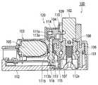
이러한 타입의 통상적인 조향 록 장치로서, 일본 특허공개 제 2009-248843 호(특허 문헌 1)에 하나가 개시되어 있다. 도 1에 도시된 바와 같이, 이러한 조향 록 장치(100)는: 코일 스프링(101)에 의해서 자동차의 조향 샤프트(미도시)의 방향(도 1의 상향 방향)으로 가압As a conventional steering lock device of this type, one disclosed in Japanese Patent Application Laid-Open No. 2009-248843 (Patent Document 1) is disclosed. 1, this
되고, 그리고 상기 조향 샤프트에 대해서 피팅될 수 있는(fittable) 록 부재(102); 상기 록 부재(102)를 구동하는 구동 본체(103); 및 상기 록 부재(102)에 인접하여 배열되고, 그리고 상기 록 부재(102)를 조향 록 위치에서 록킹할 수 있는 보조 록 메커니즘(120)을 포함한다. 또한, 상기 구동 본체(103)는: 워엄(worm)(미도시)을 통해서 모터(105)에 의해서 구동되는 회전 부재(106); 및 상기 회전 부재(106)의 회전에 의해서 상기 록 부재(102)의 이동 방향을 따라서 왕복 이동하는 캠 부재(107)를 포함하고, 상기 캠 부재(107)는 커플링 핀(108)을 통해서 록 부재(102)에 커플링된다. 상기 보조 록 메커니즘(120)은 슬라이드 플레이트(104), 홀딩 샤프트(113), 스프링 부재들(111a 및 111b), 그리고 홀딩 부재(115)로 이루어진다.And a lock member (102) fittable to the steering shaft; A
슬라이드 플레이트(104)는 상기 록 부재(102)의 측부(side) 부분의 결합 홈(109)과 결합할 수 있는 결합 돌출부(110)를 포함하고, 그리고 스프링 부재(111a)에 의해서 록 부재(102)의 방향으로 가압된다. 또한, 홀딩 샤프트(113)가 록 부재(102)의 이동 방향을 따라서 슬라이드 플레이트(104)를 향해서 프레임 커버(112)의 후방 표면으로부터 연장된다. 이러한 홀딩 샤프트(113)의 선단 단부 부분(113a)이 슬라이드 플레이트(104)의 결합 홈 부분(114)과 결합하며, 그에 의해서 슬라이드 플레이트(104)가 록 부재(102)로부터 이격된 상태로 유지된다.The
스프링 부재(111a)에 의해서, 홀딩 샤프트(113)가 슬라이드 플레이트(104)로부터 이격되는 방향으로 가압된다. 또한, 결합 핀(116)이 프레임 커버(112)의 후방 표면 내로 탈착가능하게 피팅되는 홀딩 부재(115)로부터 연장된다. 이러한 결합 핀(116)의 선단 단부가 홀딩 샤프트(113)의 후방 단부 부분(113b)과 결합하고, 그에 의해서 상기 홀딩 샤프트(113)가 슬라이드 플레이트(104)와 결합하는 상태가 유지된다.By the
전술한 구성에서, 모터(105)가 주차시에 록 방향으로 회전될 때, 회전 부재(106)가 모터(105)의 구동력에 의해서 회전되고, 그리고 캠 부재(107)가 록 부재(102)의 록 방향(도 1의 상향 방향)으로 이동한다. 그에 따라, 록 부재(102)가 코일형 스프링(101)의 가압력에 의해서 조향 록 위치로 변위된다(positionally shift). 결과적으로, 록 부재(102)의 선단 단부가 조향 샤프트로 피팅되고, 조향 샤프트의 회전이 방지됨에 따라 자동차가 조향불가능한 상태로 전환된다.When the
그 후에, 모터(105)가 록 해제 방향으로 회전될 때, 회전 부재(106)가 반대 방향으로 회전되고, 록 부재(102)가 캠 부재(107)와 함께 록 해제 위치로 변위된다. 결과적으로, 조향 샤프트에 대한 록 부재(102)의 피팅이 해제되고, 그에 따라 조향 샤프트의 회전이 자유롭게 되고, 그리고 자동차가 조향가능한 상태로 전환된다.Thereafter, when the
또한, 도 1에 도시된 이러한 록 상태에서, 홀딩 샤프트(113)가 프레임 커버(112)의 후방 표면으로부터 슬라이드 플레이트(104)를 향해서 돌출하고, 그리고 홀딩 샤프트의 선단 단부가 슬라이드 플레이트(104)의 결합 홈 부분(114)과 결합한다. 그러한 방식에서, 슬라이드 플레이트(104)가 록 부재(102)로부터 이격된 상태로 유지된다.1, the
그 후에, 불법적인 언록킹 작용에 의해서 차량의 주차시에 프레임 커버(112)로부터 조향 록 장치(100)로 외부 힘이 인가되는 경우에, 홀딩 부재(115)가 프레임 커버(112)의 후방 표면으로부터 이격되고, 그리고 테이퍼형 부분(112a)을 이동시킨다. 그러한 방식에서, 결합 핀(116)과 홀딩 샤프트(113) 사이의 결합이 분리되고, 홀딩 샤프트(113)가 프레임 커버(12) 측부로 이동하고, 그리고 홀딩 샤프트(113)가 슬라이드 플레이트(104)의 결합 홈 부분(114)으로부터 분리된다. 그에 따라, 슬라이드 플레이트(104)가 스프링 부재(111a)에 의해서 록 부재(102)의 방향으로 가압되고, 그리고 결합 돌출부(110)가 록 부재(102)의 측부 부분의 결합 홈(109)과 결합한다. 이러한 방식에서, 록 부재(102)가 조향 록 위치에서 정지되고, 그에 따라, 조향 샤프트의 회전이 방지되고, 차량이 불법적인 록 해제 동작에 의해서 조향가능하게 되는 오작동이 방지될 수 있고, 그리고 차량의 주차 시간 중의 차량 도난-방지가 강화될 수 있다.Thereafter, when an external force is applied from the
인용 리스트Citation List
특허 문헌Patent literature
PTL 1: 일본 특허공개 제 2009-248843 호PTL 1: Japanese Patent Application Laid-Open No. 2009-248843
전술한 바와 같이, 통상적인 조향 록 장치(100)에서, 프레임 커버(112)가 불법적인 언록킹 작용에 의해서 탈착되어 그 내부가 노출될 때, 모터(105), 회전 부재(106) 등이 탈착되고, 그리고 캠 부재(107)를 터치할 수 있게 된다. 그에 따라, 비록 록 부재(102)가 슬라이드 플레이트(104)에 의해서 조향 록 위치에서 유지되지만, 캠 부재(107)가 강한 힘으로 외부로 당겨지는 시도가 있는 경우에, 슬라이드 플레이트(104)가 파괴되고 그에 따라 보조 록을 해제하게 되는 결과로서, 조향 록이 해제될 수 있다는 것이 이해되고 있다.As described above, in the conventional
이와 관련하여, 본원 발명의 목적은, 커버가 탈착된 후에, 록 부재가 강한 힘으로 외부로 강제로 당겨지도록 시도되는 경우에도, 록 부재가 당겨질 수 없는 조향 록 장치를 제공하는 것이다.In this connection, it is an object of the present invention to provide a steering lock device in which a lock member can not be pulled even when a lock member is attempted to be forcedly pulled outward with a strong force after the cover is detached.
전술한 목적을 달성하기 위해서, 본원 발명의 제 1 양태는 조향 록 장치를 제공하고, 그러한 조향 록 장치는: 조향 록 위치와 조향 록 해제 위치 사이에서 자유롭게 이동가능하게 배열되는 록 부재; 불법적인 언록킹시에 상기 록 부재를 조향 록 위치에서 유지하는 보조 록 메커니즘; 및 상기 록 부재와 상기 보조 록 메커니즘 사이에 배치되고, 불법적인 언록킹시에 상기 록 부재를 상기 조향 록 위치에서 유지하기 위해서 상기 록 부재로 인가되는 로드(load)로 인해서 파열되는, 취약(fragile) 부분을 포함한다.To achieve the above-mentioned object, a first aspect of the present invention provides a steering lock device, comprising: a lock member arranged freely movably between a steering lock position and a steering lock release position; An auxiliary lock mechanism for holding said lock member in a steered lock position upon illegal unlocking; And a rupture mechanism disposed between the lock member and the auxiliary lock mechanism and adapted to rupture by a load applied to the lock member to maintain the lock member in the steered lock position upon illegal unlocking, ) Portion.
본원 발명의 제 2 양태는 조향 록 장치를 제공하고, 그러한 조향 록 장치는: 조향 록 위치와 조향 록 해제 위치 사이에서 자유롭게 슬라이딩가능하게 배열된 록 부재로서, 상기 록 부재가 상기 조향 록 위치에서 조향 샤프트와 결합하는 선단 단부를 가지는, 록 부재; 상기 록 부재 상에 제공되는 보조 결합 부분; 및 보조 록 위치와 보조 록 해제 위치 사이에서 자유롭게 슬라이딩가능하게 배열되고, 그리고 상기 보조 록 위치에 위치된 상태에서, 상기 조향 록 위치에 위치된 록 부재의 보조 결합 부분과 결합하고, 그리고 상기 조향 록 위치에서 상기 록 부재와 록킹하는 보조 록 부재를 포함하고, 상기 조향 록 장치는 보조 결합 부분보다 더 후방 단부 측부 상의 상기 록 부재의 영역 내에 제공된 취약 부분을 포함하고, 상기 취약 부분은 상기 보조 록 부재가 견딜 수 있는 로드 보다 작게 셋팅된 내성(耐性)(withstand) 로드를 가지고, 그리고 상기 보조 록 부재 및 상기 보조 결합 부분이 서로 결합된 상태에서 세팅된 값 또는 그 초과의 로드가 상기 록 부재로 인가될 때 파열된다.A second aspect of the present invention provides a steering lock apparatus, comprising: a lock member slidably and freely arranged between a steering lock position and a steering lock release position, A lock member having a leading end that engages the shaft; An auxiliary coupling portion provided on the lock member; And an auxiliary lock portion of the lock member located at the steer lock position, the main lock portion being slidably disposed between the auxiliary lock position and the auxiliary lock release position and being located at the auxiliary lock position, Wherein the steering lock device includes a vulnerable portion provided in a region of the lock member on a rear end side more than an auxiliary engagement portion, And a load with a value set at a state where the auxiliary lock member and the auxiliary coupling member are coupled to each other is greater than or equal to a value When it is broken.
또한, 본원 발명의 제 3 양태는 조향 록 장치를 제공하고, 그러한 조향 록 장치는: 커버; 상기 커버로 커버된 프레임; 상기 프레임 내에 제공된 록 안내 홀 내에 제공되고, 조향 록 위치와 조향 록 해제 위치 사이에서 자유롭게 이동가능하게 배열되며, 상기 조향 록 위치에서 조향 샤프트와 결합되는 선단 단부를 가지는 록 부재; 상기 록 부재 상에 제공된 보조 결합 부분, 상기 보조 록 위치와 상기 보조 록 해제 위치 사이에서 자유롭게 슬라이딩가능하게 상기 프레임 내에 배열되고, 그리고 상기 보조 결합 부분과의 결합의 조향 록 위치 측부까지 가압 수단에 의해서 가압되는 보조 록 부재, 그리고 상기 커버에 고정된 일 단부를 가지는 홀딩 부재를 가지는 보조 록 메커니즘을 포함하고, 상기 커버가 프레임에 조립된 상태에서, 상기 홀딩 부재의 선단 단부가 상기 보조 록 해제 위치에 위치되는 보조 록 부재의 홀딩/수용 부분과 결합되고, 그리고 보조 록 해제 위치에서 상기 보조 록 부재를 유지하고, 상기 커버가 상기 프레임에 대해서 상대적으로 이동되는 경우에, 상기 홀딩 부재와 상기 홀딩/수용 부분 사이의 결합이 분리되고, 상기 보조 록 부재가 상기 가압 수단의 가압력에 의해서 상기 보조 록 해제 위치로부터 상기 보조 록 위치까지 이동하고, 그리고 상기 보조 록 부재가 상기 조향 록 위치에 위치된 록 부재의 보조 결합 부분과 결합되고, 그리고 상기 조향 록 위치에서 상기 록 부재를 록킹하며, 상기 조향 록 장치는 상기 보조 결합 부분보다 더 후방 단부 측부 상의 상기 록 부재의 영역 내에 제공된 취약 부분을 포함하고, 상기 취약 부분은 상기 보조 록 부재가 견딜 수 있는 로드 보다 작게 셋팅된 내성 로드를 가지고, 그리고 상기 보조 록 부재 및 상기 보조 결합 부분이 서로 결합된 상태에서 세팅된 값 또는 그 초과의 로드가 상기 록 부재로 인가될 때 파열된다.Also, a third aspect of the present invention provides a steering lock device, comprising: a cover; A frame covered with the cover; A lock member provided in a lock guide hole provided in the frame and freely movably arranged between the steer lock position and the steer unlock position and having a leading end coupled with the steering shaft at the steer lock position; The auxiliary lock portion being arranged in the frame so as to be freely slidable between the auxiliary lock position and the auxiliary lock releasing position, and to the steering lock position side of the engagement with the auxiliary coupling portion by the urging means And an auxiliary lock mechanism having a holding member having one end fixed to the cover, wherein, when the cover is assembled to the frame, the leading end of the holding member is moved to the auxiliary lock releasing position Wherein the holding member is engaged with a holding / receiving portion of the auxiliary locking member to be positioned and holds the auxiliary locking member at the auxiliary locking release position, and when the cover is moved relative to the frame, The coupling between the portions is separated, and the auxiliary lock member is urged by the urging force of the urging means And the auxiliary lock member is engaged with the auxiliary engagement portion of the lock member positioned at the steering lock position and locks the lock member at the steering lock position , The steering lock device includes a vulnerable portion provided in a region of the lock member on a more rear end side than the auxiliary coupling portion and the weak portion has an immersion rod set smaller than the load the auxiliary lock member can withstand , And a rupture occurs when a value or more than a set value with the auxiliary lock member and the auxiliary coupling member engaged with each other is applied to the lock member.
상기 보조 록 부재가 플레이트-유사 슬라이드 플레이트로 제조될 수 있고, 그리고 상기 보조 결합 부분이 상기 록 부재 상에서 돌출된 커플링 핀으로 제조될 수 있을 것이다.The auxiliary lock member may be made of a plate-like slide plate, and the auxiliary coupling portion may be made of a coupling pin projecting on the lock member.
상기 취약 부분이 상기 조향 록 위치에 위치되는 록 부재의 록 안내 홀 내에 위치되는 영역 내에 제공될 수 있을 것이다.The weakened portion may be provided in an area located in the lock guide hole of the lock member located at the steering lock position.
상기 취약 부분이 견딜 수 있는 로드가, 상기 록 부재가 상기 조향 록 위치와 상기 조향 록 해제 위치 사이에서 슬라이드하는 경우에 상기 록 부재로 인가되는 로드 보다 크게 셋팅될 수 있을 것이다.A load with which the fragile portion can withstand may be set larger than a load applied to the lock member when the lock member slides between the steering lock position and the steering lock release position.
상기 취약 부분이 견딜 수 있는 로드가, 상기 보조 록 부재 및 상기 보조 결합 부분 각각이 견딜 수 있는 로드 보다 작게 셋팅될 수 있을 것이다.The load with which the fragile portion can withstand can be set smaller than the load each of which can support the auxiliary lock member and the auxiliary coupling portion.
전술한 구성에 따라서, 록 부재가 강한 힘에 의해서 외부로 강제로 당겨지는 시도의 결과로서 셋팅된 값 또는 그 초과의 로드가 취약 부분에 인가되는 경우에, 취약 부분이 파열되고, 그에 따라 록 부재를 외부로 당기는 것이 불가능해진다. 그러한 구성에서, 도난-방지가 추가적으로 강화될 수 있다.According to the above-described configuration, when the load is applied to the fragile portion as a result of an attempt to forcibly pull the lock member outward by a strong force, the fragile portion is ruptured, It is impossible to pull out the light emitting diode. In such a configuration, anti-theft can be further enhanced.
플레이트-유사 부재가 슬라이딩되고 그리고 돌출된 핀과 결합하도록 허용되는 경우에, 비교적 단순한 구성이 형성되고, 그에 따라 정확한 동작들이 실시될 수 있다. 그러한 구성에서, 도난-방지가 추가적으로 강화될 수 있다.In the case where the plate-like member is allowed to engage with the sliding and protruding pins, a relatively simple configuration is formed, and the correct operations can be carried out accordingly. In such a configuration, anti-theft can be further enhanced.
셋팅된 값 또는 그 초과의 로드가 취약 부분으로 인가되고, 그리고 취약 부분이 파열된 경우에, 록 부재가 록 안내 홀 내에서 유지되고, 남은 록 부재는 터치될 수 없고, 그리고 록 부재를 외부로 당기는 것이 불가능해진다. 그러한 구성에서, 도난-방지가 추가적으로 강화될 수 있다.When the set value or more of the load is applied to the fragile portion and the fragile portion is ruptured, the lock member is held in the lock guide hole, the remaining lock member can not be touched, It becomes impossible to pull. In such a configuration, anti-theft can be further enhanced.
록 부재가 조향 록 위치와 조향 록 해제 위치 사이에서 슬라이드되는 경우에 록 부재로 인가되는 로드 보다 더 크게 취약 부분으로 인가되는 로드가 셋팅된 경우에, 취약 부분은 일반적인 동작들에 의해서 파열되지 않는다. 그러한 구성에서, 장치 전체의 활성화 신뢰성이 향상될 수 있다.In the case where the load applied to the weakened portion is set larger than the load applied to the lock member when the lock member is slid between the steering lock position and the steered unlock position, the weakened portion is not ruptured by normal operations. In such a configuration, the activation reliability of the entire device can be improved.
취약 부분이 견딜 수 있는 로드가 보조 록 부재 및 보조 결합 부분의 각각이 견딜 수 있는 로드 보다 작게 셋팅된 경우에, 조향 록 장치에 대한 불법적인 언록킹의 시도가 있는 경우에, 록킹 부재가 외부로 당겨지기 전에 취약 부분이 파열된다. 이러한 구성으로, 도난-방지가 추가적으로 강화될 수 있다.When there is an attempt to illegally unlock the steering lock device in the case where the load with which the vulnerable portion can withstand is set to be smaller than the load capable of with each of the auxiliary lock member and the auxiliary coupling portion, The fragile area ruptures before being pulled. With this configuration, anti-theft can be additionally enhanced.
도 1은 통상적인 기술의 조향 록 장치의 조향 록 상태를 도시한 횡단면도이다.
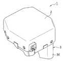
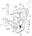
도 2는 본원 발명의 실시예를 도시한 도면으로서, 조향 록 장치의 전체적인 사시도이다.
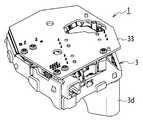
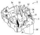
도 3은 본원 발명의 실시예를 도시한 도면으로서, 커버가 도 2로부터 탈착된 상태를 도시한 사시도이다.
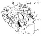
도 4는 본원 발명의 실시예를 도시한 도면으로서, 회로 기판 등이 도 3으로부터 탈착된 상태를 도시한 사시도이다.
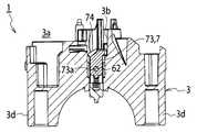
도 5는 본원 발명의 실시예를 도시한 도면으로서, 취약 부분이 파열된 후에 행거(hanger)의 후방 단부 측부가 도 4로부터 제거된 상태를 도시한 사시도이다.
도 6은 본원 발명의 실시예를 도시한 도면으로서, 도 5에서의 조향 록 상태를 도시한 사시도이다.
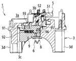
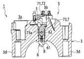
도 7은 본원 발명의 실시예를 도시한 도면으로서, 도 6의 선 VII-VII을 따라서 취한 횡단면도이다.
도 8은 본원 발명의 실시예를 도시한 도면으로서, 도 6의 선 VIII-VIII을 따라서 취한 횡단면도이다.
도 9는 본원 발명의 실시예를 도시한 도면으로서, 도 5의 조향 록 상태를 도시한 평면도이다.
도 10은 본원 발명의 실시예를 도시한 도면으로서, 도 9의 선 X-X을 따라서 취한 횡단면도이다.
도 11은 본원 발명의 실시예를 도시한 도면으로서, 도 9의 선 XI-XI을 따라서 취한 횡단면도이다.
도 12는 본원 발명의 실시예를 도시한 도면으로서, 조향 록 시점에 홀딩 샤프트가 슬라이드 플레이트와 결합하는 상태를 도시한 주요 부분의 사시도이다.
도 13은 본원 발명의 실시예를 도시한 도면으로서, 조향 록 시점에 홀딩 샤프트가 슬라이드 플레이트로부터 분리된 상태를 도시한 주요 부분의 사시도이다.
도 14는 본원 발명의 실시예를 도시한 도면으로서, 조향 록 시점에 행거가 취약 부분에서 파열되는 상태를 도시한 주요 부분의 사시도이다.1 is a cross-sectional view showing a steering lock state of a conventional steering lock device.
2 is a view showing an embodiment of the present invention, which is a general perspective view of a steering lock device.
Fig. 3 is a perspective view showing an embodiment of the present invention, in which a cover is detached from Fig. 2; Fig.
4 is a perspective view showing an embodiment of the present invention, in which a circuit board or the like is detached from Fig. 3; Fig.
Fig. 5 is a perspective view showing an embodiment of the present invention, in which a rear end side portion of a hanger is removed from Fig. 4 after a fragile portion is ruptured. Fig.
Fig. 6 is a perspective view showing the steering lock state in Fig. 5, showing the embodiment of the present invention. Fig.
Fig. 7 is a cross-sectional view taken along line VII-VII in Fig. 6, showing an embodiment of the present invention.
Fig. 8 is a cross-sectional view taken along line VIII-VIII of Fig. 6, showing the embodiment of the present invention.
Fig. 9 is a plan view showing the steering lock state of Fig. 5, showing the embodiment of the present invention.
Fig. 10 is a cross-sectional view taken along line XX of Fig. 9, showing an embodiment of the present invention.
Fig. 11 is a cross-sectional view taken along the line XI-XI in Fig. 9, showing the embodiment of the present invention.
12 is a perspective view of a main portion showing a state in which a holding shaft is engaged with a slide plate at a steering lock time point, according to an embodiment of the present invention.
13 is a perspective view of a main portion showing a state in which a holding shaft is separated from a slide plate at a steering lock time point, according to an embodiment of the present invention.
14 is a perspective view of a main portion showing a state in which a hanger is ruptured at a weak portion at a steering lock time according to an embodiment of the present invention.
이하에서는 첨부 도면들을 기초로 하는 본원 발명의 실시예에 대한 설명이 기재되어 있다.In the following, a description of an embodiment of the present invention based on the attached drawings is described.
도 2 내지 도 14에 도시된 바와 같이, 이러한 실시예의 조향 록 장치(1)는 서로 조립된 커버(2) 및 프레임(3)을 포함하고, 그리고 자동차의 조향 샤프트(미도시)를 수용하는 조향 컬럼 장치(미도시)에 부착된다.2 to 14, the
프레임(3)의 내부에: 일 측부(도 4, 도 5 등의 상부 측부)를 향해서 개방된 부품 하우징 챔버(3a); 부품 하우징 챔버(3a)의 하단 부분으로부터 조향 컬럼 장치 측부로 프레임(3)을 관통하고, 그리고 조향 샤프트의 축 방향에 수직한 방향으로 연장되는 록 안내 홀(3b); 및 이러한 록 안내 홀(3b)에 직교하는 방향으로 연장하는 보조 록 하우징 홀(3c)이 형성된다. 또한, 프레임(3)은 조향 컬럼 장치에 걸쳐지도록(straddle) 배열된 레그 부분들(3d 및 3d)의 쌍을 포함한다.Inside the frame 3: a
부품 하우징 챔버(3a)에서, 구동 공급원으로서의 모터(31); 상기 모터의 회전 샤프트의 워엄 기어(32)의 구동에 의해서 언록킹 방향 및 록킹 방향으로 회전하는 워엄 휘일(미도시); 그리고 상기 워엄 휘일을 통해서 구동되고, 그리고 후술하는 록 부재(6)에 수직인 방향으로 슬라이딩되는 슬라이드 부재(5)가 수용된다.In the
록 안내 홀(3b) 내에서, 조향 샤프트를 록 상태에서 유지하는 록 부재(6)가 수용된다. 또한, 보조 록 하우징 홀(3c) 내에, 상기 커버(2)가 상기 프레임(3)으로부터 탈착되는 경우에 록 위치에서 록 부재(6)를 유지하는 보조 록 메커니즘(9)이 수용된다.In the lock guide hole (3b), a lock member (6) for holding the steering shaft in a locked state is accommodated. An
도 5에 도시된 바와 같이, 슬라이드 부재(5)는 슬라이드 방향으로 연장되는 베이스 부분(51); 상기 베이스 부분(51)의 일 단부로부터 돌출하고, 그리고 선단 단부 측부를 향해서 조향 샤프트의 방향으로 점진적으로 경사지는 경사진 부분(52); 및 상기 슬라이딩 방향을 따라서 상기 경사진 부분(52)으로부터 돌출하는 선단 단부 부분(53)으로 이루어진다. 또한, 베이스 부분(51) 상에서, 상기 워엄 휘일과 맞물리는 랙 부분(54)이 제공된다. 또한, 부품 하우징 챔버(3a) 내에 셋팅된 록 단부와 록 해제 단부 사이에서 슬라이딩될 수 있도록, 슬라이드 부재(5)가 배열된다.As shown in Fig. 5, the
록 부재(6)는 행거(7) 및 록 본체(8)로 주로 이루어진다. 행거(7)는 록 부재(6)의 후방 단부 측부를 구성하고, 그리고 슬라이드 부재(5)와 링크된다. 록 본체(8)는 록 부재(6)의 선단 단부 측부를 구성하고, 그리고 커플링 핀(62)에 의해서 행거(7)에 커플링된다. 록 본체(8)의 선단 단부가 프레임(3)의 하단 표면 내외로 이동할 수 있도록, 그리고 프레임(3)의 하단 표면으로부터 돌출하는 상태에서 조향 샤프트로 피팅되고, 이어서 조향 샤프트(조향 록 상태)로 록킹되도록, 록 본체(8)가 배열된다. 이어서, 행거(7)와 록 본체(8) 사이에서, 가압 수단으로서 코일형 스프링(61)이 개재된다. 코일형 스프링(61)의 압축 반응력에 의해서, 록 본체(8)가 조향 록 해제 위치 측부로부터 조향 록 위치 측부로 가압된다. 또한, 커플링 핀(62)의 일 단부가 록 부재(6)로부터 돌출하고, 그리고 후술되는 보조 록 메커니즘(9)을 구성하는 보조 결합 부분(95)을 구성한다.The lock member (6) mainly consists of a hanger (7) and a lock body (8). The
도 12 내지 14에 도시된 바와 같이, 행거(7)가 베이스 부분(72) 및 커플링 부분(73)으로 주로 이루어진다. 베이스 부분(72)은 록 부재(6)의 가장 후방 단부 부분에 위치되는 경사 수용 부분(71)을 포함하고, 부품 하우징 챔버(3a)의 하단 부분을 따라서 개방되는 실질적으로 U- 형상의 단면을 가지고, 그리고 내부를 통해서 삽입된 경사 수용 부분(71)을 가진다. 이어서, 경사 수용 부분(71)의 후방 단부 측부의 엣지 부분 상에서, 록 해제 경사진 부분(71a)이 셋팅되고, 그리고 경사 수용 부분(71)의 선단 단부 측부의 엣지 부분 상에서, 록 경사진 부분(71b)이 셋팅된다.As shown in Figs. 12 to 14, the
또한, 취약 부분(74)이 록 경사진 부분(71b)의 기저(root) 부분 상에 셋팅된다. 취약 부분(74)은 보조 결합 부분(95) 보다 록 부재(6)의 후방 단부 측부(6a)에 보다 근접하여 위치되고, 그리고 그 기계적 강도가 행거(7)의 다른 영역들에 비교하여 보다 약하도록 셋팅된다. 다시 말해서, 행거(7)가 슬라이드 부재(5)의 경사진 부분(52) 상에서 이동하고, 그리고 록 부재(6)가 조향 록 위치와 조향 록 해제 위치 사이에서 이동하는 경우에, 록 부재(6)의 선단 단부가 조향 샤프트와 맞물릴 때, 록 부재(6)가 외측으로 당겨질 때 인장(tensile) 로드가 행거(7)로 인가된다. 그러한 로드에 대한 취약 부분(74)의 내성 로드는, 취약 부분(74)이 변형 또는 파열 없이 충분한 강도를 가질 수 있는 미리 결정된 값으로 셋팅된다. 또한, 후술하는 슬라이드 플레이트(91)와 보조 결합 부분(95)이 서로 결합되는 상태에서 조향 록 위치로부터 조향 록 해제 위치까지의 록 부재(6)를 당기는 방향을 따라 록 부재(6)로 로드가 인가되는 경우에, 슬라이드 플레이트(91) 및 보조 결합 부분(95)이 변형되거나 파열되기 전에 취약 부분(74)이 파열될 수 있도록 취약 부분(74)의 내성 로드가 셋팅된다. 취약 부분(74)의 치수를 다른 영역들의 치수 보다 얇게 하기 위한, 취약 부분(74)을 드릴가공하기 위한, 기타 등등을 위한 수단들에 의해서, 내성 전압이 셋팅된다.Further, the
커플링 부분(73)이 조향 샤프트의 방향을 따라(즉, 록 부재(6)의 선단 단부 측부로) 베이스 부분(72)으로부터 돌출하고, 그리고 커플링 핀(62)을 통해서 록 본체(8)에 커플링된다. 폭 방향으로의 커플링 부분(73)의 표면(넓은 표면)이 조향 샤프트의 축 방향과 평행하게 배열되고, 그리고 커플링 핀(62)이 피팅되는 둥근 홀(73a)이 폭 방향으로 연장된다.The
도 12 내지 14에 도시된 바와 같이, 록 본체(8)의 후방 단부-측부 단부 상에서, 행거(7)의 방향(즉, 도 12 내지 14에서 상향)으로 돌출하는 아암 부분들(81 및 82)의 쌍이 제공되고, 그리고 각각의 아암 부분들(81 및 82)에서, 행거(7)의 이동 방향으로 길게 늘어진 긴 홀들(미도시)이 제공되고, 그리고 커플링 핀(62)이 긴 홀들 내로 이동가능하게 삽입된다. 상기 아암 부분들(81 및 82) 사이에 위치된 록 본체(8)의 커버(2)-측부 단부 부분에서, 코일형 스프링(61)의 타단부를 수용하는 스프링 안착-대기(seat-ready) 홀(83)이 형성된다.12 to 14, the
보조 록 메커니즘(9)은: 록 부재(6)의 플레이트 두께 방향을 따라서 상기 록 부재(6)의 넓은 표면으로부터 연장되는 슬라이드 플레이트(보조 록 부재)(91); 상기 록 부재(6)의 커플링 핀(62)의 방향으로 상기 슬라이드 플레이트(91)를 가압하는 코일형 스프링(가압 수단)(92); 상기 커버(2)의 내측 표면 상에서 돌출된 홀딩 샤프트(홀딩 부재)(21); 전술한 커플링 핀(62)의 일 단부(보조 결합 부분(95))로 이루어진다.The
슬라이드 플레이트(91) 및 코일형 스프링(92)이 록 부재(6)의 넓은 표면(B) 보다 더 외부에 배열되며, 그에 따라 슬라이드 플레이트(91)가 조향 록 위치에 위치된 록 부재의 돌출부와 결합하는 보조 록 위치와 슬라이드 플레이트(91)가 상기 록 부재의 슬라이드를 허용하는 보조 록 해제 위치 사이에서 슬라이딩될 수 있다. 또한, 도 12에 도시된 바와 같이, 슬라이드 플레이트(91)의 하나의 단부 측부 상에서, 결합 리세스형(recessed) 부분(홀딩/수용 부분)(93)이 형성되고, 상기 결합 리세스형 부분에는 상기 커버(2)의 후방 표면으로부터 내부로 돌출하는 홀딩 샤프트(21)의 선단 단부가 결합된다. 슬라이드 플레이트(91)의 다른 단부 상에서, 이분형(bifurcated) 결합 단부 부분(94)이 형성되고, 그러한 이분형 결합 단부 부분(94)은 상부 및 하부 측부들로부터 커플링 핀(62)을 샌드위치시키는 방식으로 커플링 핀(62)을 수용한다.The
홀딩 샤프트(21)가 샤프트 형상으로 형성되고, 그리고 하나의 표면이 개방되는 박스 형상을 구비하는 커버(2)의 내부 표면 상에서 커버(2)와 일체로 형성된다. 이어서, 홀딩 샤프트(21)와 관련하여, 커버(2)가 프레임(3)에 조립된 상태에서, 관련된 홀딩 샤프트(21)의 선단 단부가 보조 록 해제 위치에 위치된 슬라이드 플레이트(91)의 결합 리세스형 부분(93)과 결합하고, 그리고 슬라이드 플레이트(91)는 보조 록 해제 위치에서 유지된다. 또한, 커버(2)가 프레임(3)으로부터 이격될 때, 홀딩 샤프트(21)와 결합 리세스형 부분(93) 사이의 결합이 분리되고, 그리고 슬라이드 플레이트(91)가 코일형 스프링(92)의 가압력에 의해서 보조 록 위치로 이동된다.The holding
다음에, 전술한 조향 록 장치(1)의 동작들에 대해서 설명한다. 모터(31)가 활성화될 때, 모터(31)의 구동력이 랙 부분(54)을 통해서 슬라이드 부재(5)로 전달되고, 그리고 슬라이드 부재(5)가 슬라이드된다. 이어서, 슬라이드 부재(5)가 록 단부 측부로 슬라이드되는 경우에, 행거(7)의 록 경사진 부분(71b)이 경사진 부분(52) 상에서 이동하고, 그에 의해서 록 부재(6)가 조향 샤프트의 회전을 방지하는 조향 록 위치로 이동하고, 그리고 록 본체(8)가 프레임(3)의 하단 표면으로부터 돌출하고, 그리고 조향 샤프트에 피팅된다. 결과적으로, 조향 샤프트의 회전이 방지되고, 그에 따라, 자동자가 조향불가능한 상태(조향 록 상태)로 유지된다. 또한, 슬라이드 부재(5)가 록 해제 단부 측부로 슬라이드하는 경우에, 록 해제 경사진 부분(71a)이 경사진 부분(52) 상에서 이동하고, 그에 의해서 록 부재(6)가, 조향 샤프트의 회전을 허용하는 조향 록 해제 위치로 이동하고, 록 본체(8)는 프레임(3) 내로 후퇴되고, 조향 샤프트의 회전이 허용된다. 따라서, 자동차가 조향가능한 상태(조향 록 해제 상태)로 전환된다.Next, the operations of the above-described
또한, 전술한 조향 록 상태에서, 도 12에 도시된 바와 같이, 코일형 스프링(92)의 가압력에 의해서, 슬라이드 플레이트(91)가 보조 록 위치 측부로 가압되고 그러한 측부 상에서 유지된다. 커버(2)가 불법적인 작용에 의해서 프레임(3)으로부터 탈착되는 경우에, 도 13에 도시된 바와 같이, 커버(2)의 홀딩 샤프트(21)가 슬라이드 플레이트(91)의 결합 리세스형 부분(93)으로부터 분리된다. 결과적으로, 슬라이드 플레이트(91)가 보조 록 해제 위치로부터 보조 록 위치로 이동하고, 그리고 상기 슬라이드 플레이트(91)의 결합 단부 부분(94)이 록 본체(8)의 커플링 핀(62)과, 상부 및 하부 측부들로부터 상기 커플링 핀(62)을 샌드위치시키는 방식으로, 결합한다. 그러한 방식에서, 록 부재(6)(행거(7) 및 록 본체(8))의 이동이 방지되고, 그리고 록 본체(8)에 의한 조향 록 상태가 유지된다.12, by the urging force of the coil-shaped
이어서, 회로 기판(33), 모터(31), 워엄 휘일 등이 추가적인 불법적인 언록킹 작용에 의해서 탈착될 때, 행거(7)가 노출된다. 행거(7)를 강한 힘으로 강제로 외부로 당기기 위한 시도의 결과로서의 상태로부터 셋팅 값 또는 그 초과의 로드가 행거(7)로 인가될 때, 도 14에 도시된 바와 같이, 행거(7)가 취약 부분(74)에서 파열된다. 그러한 방식에서, 남은 행거(7)가 외부로 당겨질 수 없다. 또한, 남은 행거(7)가 록 안내 홀(3b)의 깊은 지점에 위치되고, 따라서 남은 행거(7) 및 록 본체(8)가 터치될 수 없고, 이는 록 부재(6)를 당길 수 없게 하고, 그리고 조향 록 상태가 유지되게 한다.Then, the
전술한 내용으로부터, 조향 록 장치의 구성을 복잡하게 하지 않고도, 조향 록 장치의 도난-방지가 강화될 수 있다.From the foregoing, theft-prevention of the steering lock device can be enhanced without complicating the configuration of the steering lock device.
이러한 실시예에서, 취약 부분(74)이 록 경사진 부분(71b)의 기저 부분(U-형상의 선단 단부-측부 모서리 부분) 상에 셋팅된다. 그러나, 이러한 것으로 제한되지 않고, 취약 부분(74a)(도 12 참조)을 행거(7)의 영역 내에 셋팅할 수도 있을 것이고, 그러한 행거(7)의 영역은, 록 해제 경사진 부분(71a)의 기저 부분(U-형상의 후방 단부-측부 모서리 부분)에서와 같이, 후방 단부 측부(6a) 상에 보다 많이 위치된다.In this embodiment, the weakened
또한, 이러한 실시예에서, 하나의 취약 부분이 행거(7) 내에 셋팅되었으나; 둘 이상의 취약 부분들이 셋팅될 수 있을 것이고, 그리고 록 부재(6)의 선단 단부 측부 상의 취약 부분(74)의 내성 로드가 록 부재의 후방 단부 측부 상의 취약 부분(74a)의 내성 로드 보다 더 크게 셋팅될 수 있을 것이다. 그러한 구성에서, 록 부재(6)를 강한 힘으로 강제로 외부로 당기려는 시도가 있는 경우에, 첫 번째로, 최후방 단부 상의 취약 부분(74a)이 파열된다. 이어서, 록 부재(6)가 추가적으로 외부로 당겨진다면, 다음에, 그러한 쌍 내의 다른 것으로서의 취약 부분(75)이 파열되고, 그리고 록 부재(6)를 외부로 당기는 것이 불가능해진다. 그러한 방식에서, 불법적인 언록킹을 실시하는데 너무 많은 시간이 소요되고, 그리고 또한, 결국에는 언록킹이 전혀 실시될 수 없게 된다. 따라서, 도난-방지가 추가적으로 강화될 수 있다.Also, in this embodiment, one vulnerable portion was set in the
또한, 이러한 실시예에서, 커버(2)가 프레임(3)으로부터 탈착되는 내용에 의해서, 홀딩 샤프트(21)와 결합 리세스형 부분(93) 사이의 결합이 해제되도록, 그리고 슬라이드 플레이트(91)가 보조 록 해제 위치로부터 보조 록 위치로 이동하는 것이 허용되도록, 구성이 채택된다. 그러나, 이러한 것으로 제한되지 않고, 커버(2)가 프레임(3) 상에서 회전하는 내용 등에 의해서, 홀딩 샤프트(21)가 프레임(3) 상에서 상대적으로 이동하고, 홀딩 샤프트(21)와 결합 리세스형 부분(93) 사이의 결합이 해제되고, 그리고 슬라이드 플레이트가 보조 록 해제 위치 및 보조 록 위치로부터 이동하는 것이 허용되는 구성이 채택될 수 있을 것이다.
The engagement between the holding
Claims (7)
Translated fromKorean조향 록 위치와 조향 록 해제 위치 사이에서 자유롭게 이동가능하게 배열되는 록 부재;
불법적인 언록킹시에 상기 록 부재를 조향 록 위치에서 유지하는 보조 록 메커니즘; 및
상기 록 부재와 상기 보조 록 메커니즘 사이에 배치되고, 불법적인 언록킹시에 상기 록 부재를 상기 조향 록 위치에서 유지하기 위해서 상기 록 부재로 인가되는 로드로 인해서 파열되는, 취약 부분을 포함하고,
상기 취약 부분은, 상기 보조 록 부재가 견딜 수 있는 로드 보다 작게 셋팅된 내성 로드를 가지고,
상기 취약 부분의 내성 로드는, 상기 록 부재가 상기 조향 록 위치와 상기 조향 록 해제 위치 사이에서 슬라이드하는 경우에, 상기 록 부재가 견딜 수 있는 로드 보다 크게 셋팅되는, 조향 록 장치.A steering lock device comprising:
A lock member arranged to be freely movable between a steering lock position and a steering lock release position;
An auxiliary lock mechanism for holding said lock member in a steered lock position upon illegal unlocking; And
And a rupture portion disposed between the lock member and the auxiliary lock mechanism and ruptured by a rod applied to the lock member to hold the lock member in the steered lock position at the time of illegal unlocking,
The weak portion has an immunity rod set to be smaller than a load with which the auxiliary lock member can withstand,
And the resilient rod of the fragile portion is set larger than the rod that the locking member can withstand when the locking member slides between the steering lock position and the steering lock release position.
조향 록 위치와 조향 록 해제 위치 사이에서 자유롭게 슬라이딩가능하게 배열된 록 부재로서, 상기 록 부재가 상기 조향 록 위치에서 조향 샤프트와 결합하는 선단 단부를 가지는, 록 부재;
상기 록 부재 상에 제공되는 보조 결합 부분; 및
보조 록 위치와 보조 록 해제 위치 사이에서 자유롭게 슬라이딩가능하게 배열되고, 그리고 상기 보조 록 위치에 위치된 상태에서, 상기 조향 록 위치에 위치된 록 부재의 보조 결합 부분과 결합하고, 그리고 상기 조향 록 위치에서 상기 록 부재를 록킹하는 보조 록 부재를 포함하고,
상기 록 부재는 상기 보조 결합 부분보다 더 후방 단부 측부 상의 영역에 제공된 취약 부분을 포함하고, 상기 취약 부분은 상기 보조 록 부재가 견딜 수 있는 로드 보다 작게 셋팅된 내성 로드를 가지고, 그리고 상기 보조 록 부재 및 상기 보조 결합 부분이 서로 결합된 상태에서 세팅된 값 또는 그 초과의 로드가 상기 록 부재로 인가될 때 파열되며,
상기 취약 부분이 견딜 수 있는 로드는, 상기 록 부재가 상기 조향 록 위치와 상기 조향 록 해제 위치 사이에서 슬라이드하는 경우에, 상기 록 부재가 견딜 수 있는 로드 보다 크게 셋팅되는, 조향 록 장치.A steering lock device comprising:
A lock member which is freely slidably arranged between a steering lock position and a steering lock release position, the lock member having a leading end at which the steering member engages with the steering shaft at the steering lock position;
An auxiliary coupling portion provided on the lock member; And
Engages with the auxiliary engagement portion of the lock member located at the steering lock position and is arranged to be freely slidable between the auxiliary lock position and the auxiliary lock release position and is located at the auxiliary lock position, And an auxiliary lock member that locks the lock member in the first direction,
Wherein the locking member includes a vulnerable portion provided in an area on the rear end side more than the auxiliary coupling portion and the weak portion has an immunity rod set smaller than a load that the auxiliary locking member can withstand, And a rupture when a load or a value set in a state where the auxiliary coupling portions are coupled to each other is applied to the lock member,
Wherein the rod capable of withstanding the fragile portion is set larger than the rod with which the locking member can withstand when the locking member slides between the steering lock position and the steering lock release position.
커버;
상기 커버로 커버된 프레임;
상기 프레임 내에 제공된 록 안내 홀 내에 제공되고, 조향 록 위치와 조향 록 해제 위치 사이에서 자유롭게 이동가능하게 배열되며, 상기 조향 록 위치에서 조향 샤프트와 결합되는 선단 단부를 가지는 록 부재; 및
상기 록 부재 상에 제공된 보조 결합 부분, 보조 록 위치와 보조 록 해제 위치 사이에서 자유롭게 슬라이딩가능하게 상기 프레임 내에 배열되고, 그리고 상기 보조 결합 부분과의 결합의 조향 록 위치 측부까지 가압 수단에 의해서 가압되는 보조 록 부재, 그리고 상기 커버에 고정된 일 단부를 가지는 홀딩 부재를 가지는 보조 록 메커니즘을 포함하고,
상기 커버가 프레임에 조립된 상태에서, 상기 홀딩 부재의 선단 단부가 상기 보조 록 해제 위치에 위치되는 보조 록 부재의 홀딩/수용 부분과 결합되고, 그리고 보조 록 해제 위치에서 상기 보조 록 부재를 유지하고,
상기 커버가 상기 프레임으로부터 상대적으로 이동되는 경우에, 상기 홀딩 부재와 상기 홀딩/수용 부분 사이의 결합이 분리되고, 상기 보조 록 부재가 상기 가압 수단의 가압력에 의해서 상기 보조 록 해제 위치로부터 상기 보조 록 위치까지 이동하고, 그리고 상기 보조 록 부재가 상기 조향 록 위치에 위치된 록 부재의 보조 결합 부분과 결합되고, 그리고 상기 조향 록 위치에서 상기 록 부재를 록킹하도록, 상기 홀딩 부재의 선단 단부가 상기 보조 록 부재의 홀딩/수용 부분과 결합하고,
상기 록 부재는 상기 보조 결합 부분보다 더 후방 단부 측부 상의 영역에서 취약 부분을 포함하고, 상기 취약 부분은 상기 보조 록 부재가 견딜 수 있는 로드 보다 작게 셋팅된 내성 로드를 가지고, 그리고 상기 보조 록 부재 및 상기 보조 결합 부분이 서로 결합된 상태에서 세팅된 값 또는 그 초과의 로드가 상기 록 부재로 인가될 때 파열되고,
상기 취약 부분이 견딜 수 있는 로드는, 상기 록 부재가 상기 조향 록 위치와 상기 조향 록 해제 위치 사이에서 슬라이드하는 경우에, 상기 록 부재가 견딜 수 있는 로드 보다 크게 셋팅되는, 조향 록 장치.A steering lock device comprising:
cover;
A frame covered with the cover;
A lock member provided in a lock guide hole provided in the frame and freely movably arranged between the steer lock position and the steer unlock position and having a leading end coupled with the steering shaft at the steer lock position; And
The auxiliary coupling portion provided on the lock member, the auxiliary lock portion being arranged in the frame freely slidable between the auxiliary lock position and the auxiliary lock release position, and being pressed by the pressing means to the steering lock position side of the coupling with the auxiliary coupling portion An auxiliary lock member, and an auxiliary lock mechanism having a holding member having an end fixed to the cover,
The leading end of the holding member is engaged with the holding / receiving portion of the auxiliary lock member which is located at the auxiliary lock releasing position and the auxiliary lock member is held at the auxiliary lock releasing position ,
The engagement between the holding member and the holding / receiving portion is separated when the cover is relatively moved from the frame, and the auxiliary lock member is moved from the auxiliary lock releasing position to the auxiliary lock by the urging force of the pressing means, And the auxiliary lock member is engaged with the auxiliary engagement portion of the lock member positioned at the steering lock position and the leading end of the holding member is locked with the auxiliary member to lock the lock member in the steering lock position, Engages the holding / receiving portion of the lock member,
Wherein the locking member includes a vulnerable portion in a region on the rear end side more than the auxiliary coupling portion and the weak portion has an immunity rod that is set smaller than a load that the auxiliary locking member can withstand, The auxiliary coupling portions are ruptured when a load or a set value is applied to the lock member in a state where the auxiliary coupling portions are engaged with each other,
Wherein the rod capable of withstanding the fragile portion is set larger than the rod with which the locking member can withstand when the locking member slides between the steering lock position and the steering lock release position.
상기 보조 록 부재가 플레이트-유사 슬라이드 플레이트로 제조되고, 그리고
상기 보조 결합 부분이 상기 록 부재 상에서 돌출된 커플링 핀으로 제조되는, 조향 록 장치.The method according to claim 2 or 3,
The auxiliary lock member is made of a plate-like slide plate, and
And the auxiliary coupling portion is made of a coupling pin protruding from the lock member.
상기 취약 부분이 상기 조향 록 위치에 위치되는 록 부재의 록 안내 홀 내에 위치되는 영역 내에 제공되는, 조향 록 장치.The method according to claim 2 or 3,
And the weak portion is provided in an area located in a lock guide hole of a lock member positioned at the steer-lock position.
상기 취약 부분이 견딜 수 있는 로드가, 상기 보조 록 부재 및 상기 보조 결합 부분 각각이 견딜 수 있는 로드 보다 작게 셋팅되는, 조향 록 장치.
The method according to claim 2 or 3,
Wherein the load with which the fragile portion can withstand is set to be smaller than a load with which each of the auxiliary lock member and the auxiliary coupling portion can withstand.
Applications Claiming Priority (3)
| Application Number | Priority Date | Filing Date | Title |
|---|---|---|---|
| JPJP-P-2011-082645 | 2011-04-04 | ||
| JP2011082645AJP5809831B2 (en) | 2011-04-04 | 2011-04-04 | Steering lock device |
| PCT/JP2012/002029WO2012137436A1 (en) | 2011-04-04 | 2012-03-23 | Steering lock device |
Publications (2)
| Publication Number | Publication Date |
|---|---|
| KR20130133068A KR20130133068A (en) | 2013-12-05 |
| KR101504450B1true KR101504450B1 (en) | 2015-03-19 |
Family
ID=46026875
Family Applications (1)
| Application Number | Title | Priority Date | Filing Date |
|---|---|---|---|
| KR1020137028704AExpired - Fee RelatedKR101504450B1 (en) | 2011-04-04 | 2012-03-23 | Steering lock device |
Country Status (10)
| Country | Link |
|---|---|
| US (1) | US8925416B2 (en) |
| EP (1) | EP2694337B1 (en) |
| JP (1) | JP5809831B2 (en) |
| KR (1) | KR101504450B1 (en) |
| CN (1) | CN103502063B (en) |
| AU (1) | AU2012239630B2 (en) |
| BR (1) | BR112013024884A2 (en) |
| MX (1) | MX338310B (en) |
| RU (1) | RU2542808C1 (en) |
| WO (1) | WO2012137436A1 (en) |
Families Citing this family (8)
| Publication number | Priority date | Publication date | Assignee | Title |
|---|---|---|---|---|
| WO2013054821A1 (en)* | 2011-10-11 | 2013-04-18 | 日本精工株式会社 | Steering column and method for producing same |
| JP5956780B2 (en)* | 2012-03-01 | 2016-07-27 | 株式会社アルファ | Electric steering lock device |
| JP5965202B2 (en)* | 2012-04-27 | 2016-08-03 | 株式会社アルファ | Steering lock device |
| US10093276B2 (en)* | 2013-10-03 | 2018-10-09 | Alpha Corporation | Steering lock device |
| JP6278829B2 (en)* | 2014-05-16 | 2018-02-14 | 株式会社アルファ | Steering lock device |
| US20160132205A1 (en)* | 2014-11-07 | 2016-05-12 | Ebay Inc. | System and method for linking applications |
| US10044710B2 (en) | 2016-02-22 | 2018-08-07 | Bpip Limited Liability Company | Device and method for validating a user using an intelligent voice print |
| JP6166427B1 (en)* | 2016-06-02 | 2017-07-19 | 株式会社東海理化電機製作所 | Steering lock device |
Citations (2)
| Publication number | Priority date | Publication date | Assignee | Title |
|---|---|---|---|---|
| JP2009227056A (en) | 2008-03-21 | 2009-10-08 | Mazda Motor Corp | Steering locking device of vehicle |
| KR20090125116A (en)* | 2007-03-29 | 2009-12-03 | 가부시키가이샤 알파 | Steering lock device |
Family Cites Families (10)
| Publication number | Priority date | Publication date | Assignee | Title |
|---|---|---|---|---|
| FR2810284B1 (en) | 2000-06-20 | 2002-09-06 | Valeo Securite Habitacle | STEERING COLUMN LOCK WITH PENEER LOCKING MEANS |
| JP3832629B2 (en)* | 2001-07-10 | 2006-10-11 | 株式会社ユーシン | Steering lock device |
| JP4980853B2 (en)* | 2006-11-10 | 2012-07-18 | 株式会社アルファ | Electric steering lock device |
| JP4991329B2 (en)* | 2007-01-30 | 2012-08-01 | 株式会社東海理化電機製作所 | Assembly method of electric steering lock device |
| DE102007034481A1 (en)* | 2007-07-20 | 2009-01-22 | Huf Hülsbeck & Fürst Gmbh & Co. Kg | Locking device with locking part |
| EP2330320A3 (en)* | 2007-10-31 | 2011-11-02 | U-Shin Ltd. | Motor-driven actuator |
| JP4629751B2 (en) | 2008-04-09 | 2011-02-09 | 株式会社ユーシン | Steering lock device |
| RU81928U1 (en)* | 2008-06-23 | 2009-04-10 | Григорий Яковлевич Шлеппер | MECHANICAL ANTI-THEFT DEVICE |
| JP5465851B2 (en)* | 2008-08-05 | 2014-04-09 | 株式会社アルファ | Steering lock device |
| JP5385724B2 (en)* | 2008-08-29 | 2014-01-08 | 株式会社アルファ | Steering lock device |
- 2011
- 2011-04-04JPJP2011082645Apatent/JP5809831B2/enactiveActive
- 2012
- 2012-03-23MXMX2013011059Apatent/MX338310B/enactiveIP Right Grant
- 2012-03-23AUAU2012239630Apatent/AU2012239630B2/ennot_activeCeased
- 2012-03-23CNCN201280016787.XApatent/CN103502063B/enactiveActive
- 2012-03-23USUS14/009,624patent/US8925416B2/enactiveActive
- 2012-03-23BRBR112013024884Apatent/BR112013024884A2/ennot_activeApplication Discontinuation
- 2012-03-23KRKR1020137028704Apatent/KR101504450B1/ennot_activeExpired - Fee Related
- 2012-03-23WOPCT/JP2012/002029patent/WO2012137436A1/enactiveApplication Filing
- 2012-03-23EPEP12718756.5Apatent/EP2694337B1/enactiveActive
- 2012-03-23RURU2013148998/11Apatent/RU2542808C1/ennot_activeIP Right Cessation
Patent Citations (2)
| Publication number | Priority date | Publication date | Assignee | Title |
|---|---|---|---|---|
| KR20090125116A (en)* | 2007-03-29 | 2009-12-03 | 가부시키가이샤 알파 | Steering lock device |
| JP2009227056A (en) | 2008-03-21 | 2009-10-08 | Mazda Motor Corp | Steering locking device of vehicle |
Also Published As
| Publication number | Publication date |
|---|---|
| BR112013024884A2 (en) | 2017-10-31 |
| MX338310B (en) | 2016-04-12 |
| JP5809831B2 (en) | 2015-11-11 |
| AU2012239630A1 (en) | 2013-10-10 |
| JP2012218461A (en) | 2012-11-12 |
| MX2013011059A (en) | 2013-11-01 |
| CN103502063B (en) | 2016-02-10 |
| RU2542808C1 (en) | 2015-02-27 |
| US8925416B2 (en) | 2015-01-06 |
| WO2012137436A1 (en) | 2012-10-11 |
| EP2694337A1 (en) | 2014-02-12 |
| KR20130133068A (en) | 2013-12-05 |
| CN103502063A (en) | 2014-01-08 |
| US20140026708A1 (en) | 2014-01-30 |
| EP2694337B1 (en) | 2017-08-02 |
| AU2012239630B2 (en) | 2015-06-04 |
Similar Documents
| Publication | Publication Date | Title |
|---|---|---|
| KR101504450B1 (en) | Steering lock device | |
| EP2330000B1 (en) | Steering lock device | |
| KR20090056837A (en) | Electric steering lock device | |
| US11555339B2 (en) | Lock device | |
| AU2012239629B2 (en) | Steering lock device | |
| JP2014231242A (en) | Steering lock device | |
| EP2578457B1 (en) | Steering lock device | |
| JP4881843B2 (en) | Steering lock device | |
| WO2015182598A1 (en) | Steering lock device | |
| JP5205296B2 (en) | Steering lock device | |
| JP5956819B2 (en) | Steering lock device | |
| JP5965202B2 (en) | Steering lock device | |
| JP5022880B2 (en) | Steering lock device | |
| JP5551565B2 (en) | Steering lock device | |
| JP4680056B2 (en) | Electric steering lock system | |
| JP5986909B2 (en) | Steering lock device | |
| CN110446633B (en) | Steering lock device | |
| JP5180018B2 (en) | Steering lock device | |
| KR20090080388A (en) | Steering lock device interworking with electronic authentication system and its manufacturing method | |
| KR20090080409A (en) | Steering lock device interworking with electronic authentication system and its manufacturing method |
Legal Events
| Date | Code | Title | Description |
|---|---|---|---|
| A201 | Request for examination | ||
| E13-X000 | Pre-grant limitation requested | St.27 status event code:A-2-3-E10-E13-lim-X000 | |
| PA0105 | International application | St.27 status event code:A-0-1-A10-A15-nap-PA0105 | |
| PA0201 | Request for examination | St.27 status event code:A-1-2-D10-D11-exm-PA0201 | |
| PG1501 | Laying open of application | St.27 status event code:A-1-1-Q10-Q12-nap-PG1501 | |
| E902 | Notification of reason for refusal | ||
| PE0902 | Notice of grounds for rejection | St.27 status event code:A-1-2-D10-D21-exm-PE0902 | |
| P11-X000 | Amendment of application requested | St.27 status event code:A-2-2-P10-P11-nap-X000 | |
| P13-X000 | Application amended | St.27 status event code:A-2-2-P10-P13-nap-X000 | |
| E701 | Decision to grant or registration of patent right | ||
| PE0701 | Decision of registration | St.27 status event code:A-1-2-D10-D22-exm-PE0701 | |
| GRNT | Written decision to grant | ||
| PR0701 | Registration of establishment | St.27 status event code:A-2-4-F10-F11-exm-PR0701 | |
| PR1002 | Payment of registration fee | St.27 status event code:A-2-2-U10-U12-oth-PR1002 Fee payment year number:1 | |
| PG1601 | Publication of registration | St.27 status event code:A-4-4-Q10-Q13-nap-PG1601 | |
| FPAY | Annual fee payment | Payment date:20180313 Year of fee payment:4 | |
| PR1001 | Payment of annual fee | St.27 status event code:A-4-4-U10-U11-oth-PR1001 Fee payment year number:4 | |
| FPAY | Annual fee payment | Payment date:20190212 Year of fee payment:5 | |
| PR1001 | Payment of annual fee | St.27 status event code:A-4-4-U10-U11-oth-PR1001 Fee payment year number:5 | |
| PC1903 | Unpaid annual fee | St.27 status event code:A-4-4-U10-U13-oth-PC1903 Not in force date:20200314 Payment event data comment text:Termination Category : DEFAULT_OF_REGISTRATION_FEE | |
| PC1903 | Unpaid annual fee | St.27 status event code:N-4-6-H10-H13-oth-PC1903 Ip right cessation event data comment text:Termination Category : DEFAULT_OF_REGISTRATION_FEE Not in force date:20200314 |