KR101501635B1 - Variable external fixation device - Google Patents
Variable external fixation deviceDownload PDFInfo
- Publication number
- KR101501635B1 KR101501635B1KR20140130885AKR20140130885AKR101501635B1KR 101501635 B1KR101501635 B1KR 101501635B1KR 20140130885 AKR20140130885 AKR 20140130885AKR 20140130885 AKR20140130885 AKR 20140130885AKR 101501635 B1KR101501635 B1KR 101501635B1
- Authority
- KR
- South Korea
- Prior art keywords
- disposed
- hinge
- fastening plate
- bracket
- body portion
- Prior art date
- Legal status (The legal status is an assumption and is not a legal conclusion. Google has not performed a legal analysis and makes no representation as to the accuracy of the status listed.)
- Active
Links
- 238000010168coupling processMethods0.000claimsdescription27
- 238000005859coupling reactionMethods0.000claimsdescription27
- 230000008878couplingEffects0.000claimsdescription25
- 238000000034methodMethods0.000claimsdescription21
- 230000002093peripheral effectEffects0.000claimsdescription4
- 230000001939inductive effectEffects0.000claims1
- 230000000149penetrating effectEffects0.000abstractdescription3
- 210000004872soft tissueAnatomy0.000description6
- 230000022159cartilage developmentEffects0.000description3
- 210000000988bone and boneAnatomy0.000description2
- 230000006378damageEffects0.000description2
- 238000010586diagramMethods0.000description2
- 208000015181infectious diseaseDiseases0.000description2
- 208000014674injuryDiseases0.000description2
- 238000000554physical therapyMethods0.000description2
- 230000008733traumaEffects0.000description2
- 208000027205Congenital diseaseDiseases0.000description1
- 206010033372Pain and discomfortDiseases0.000description1
- 230000015572biosynthetic processEffects0.000description1
- 210000004204blood vesselAnatomy0.000description1
- 238000007796conventional methodMethods0.000description1
- 230000007547defectEffects0.000description1
- 201000010099diseaseDiseases0.000description1
- 208000037265diseases, disorders, signs and symptomsDiseases0.000description1
- 238000009434installationMethods0.000description1
- 230000001678irradiating effectEffects0.000description1
- 230000007774longtermEffects0.000description1
- 230000004048modificationEffects0.000description1
- 238000012986modificationMethods0.000description1
- 210000003205muscleAnatomy0.000description1
- 210000005036nerveAnatomy0.000description1
- 230000001537neural effectEffects0.000description1
- 230000000399orthopedic effectEffects0.000description1
- 230000035515penetrationEffects0.000description1
- 238000010837poor prognosisMethods0.000description1
- 230000000451tissue damageEffects0.000description1
- 231100000827tissue damageToxicity0.000description1
Images


Classifications
- A—HUMAN NECESSITIES
- A61—MEDICAL OR VETERINARY SCIENCE; HYGIENE
- A61B—DIAGNOSIS; SURGERY; IDENTIFICATION
- A61B17/00—Surgical instruments, devices or methods
- A61B17/56—Surgical instruments or methods for treatment of bones or joints; Devices specially adapted therefor
- A61B17/58—Surgical instruments or methods for treatment of bones or joints; Devices specially adapted therefor for osteosynthesis, e.g. bone plates, screws or setting implements
- A61B17/60—Surgical instruments or methods for treatment of bones or joints; Devices specially adapted therefor for osteosynthesis, e.g. bone plates, screws or setting implements for external osteosynthesis, e.g. distractors, contractors
- A61B17/62—Ring frames, i.e. devices extending around the bones to be positioned
Landscapes
- Health & Medical Sciences (AREA)
- Orthopedic Medicine & Surgery (AREA)
- Life Sciences & Earth Sciences (AREA)
- Surgery (AREA)
- Biomedical Technology (AREA)
- Engineering & Computer Science (AREA)
- Nuclear Medicine, Radiotherapy & Molecular Imaging (AREA)
- Heart & Thoracic Surgery (AREA)
- Medical Informatics (AREA)
- Molecular Biology (AREA)
- Animal Behavior & Ethology (AREA)
- General Health & Medical Sciences (AREA)
- Public Health (AREA)
- Veterinary Medicine (AREA)
- Surgical Instruments (AREA)
Abstract
Description
Translated fromKorean본 발명의 실시예들은 골절 정복 및 변형 교정을 위한 절골술 후 고정에 사용되는 외고정장치에 가변형 경첩을 적용한 기기에 관한 것으로, 특히 골절 및 연부조직이 손상되는 상태에 따라 다양하고 간편하게 설치되며, 관절의 조기운동이 가능하도록 하여 치료와 동시에 운동을 할 수 있도록 하는 가변 외 고정 장치에 관한 것이다.
Embodiments of the present invention relate to a device using variable hinges applied to an external fixation device used for fixation after osteotomy for fracture reduction and deformation correction. The device is variously and conveniently installed depending on the state of fracture and soft tissue damage, Thereby enabling early exercise and enabling exercise simultaneously with the treatment.
일반적으로 골절에 사용되는 외 고정 장치는 크게 단순 외 고정 장치, 클램프 외 고정 장치, 그리고 링 외 고정 장치로 나눌 수 있다.In general, external fixation devices used for fracture can be roughly divided into simple external fixation device, clamp external fixation device, and external ring fixation device.
상기 단순 외 고정 장치는 하나의 클램프에 하나의 고정핀을 삽입하여 로드에 고정하는 것으로, 연부조직의 상태에 따라 다양하게 설치할 수 있으나 골절된 사지에서는 설치하기가 힘들고, 골절부위의 일측면으로만 고정하게 되므로 안정성이 떨어지는 단점이 있으며, 특히 골절편이 짧은 경우에 핀 사이의 거리가 짧아져 안정된 고정상태를 얻기가 힘든 문제점이 있다. 따라서, 상기 단순 외 고정 장치의 경우, 골절 부위의 안정성을 얻기 위해서는 상당히 부피가 큰 외부 구조물을 장착하여야 하는 문제가 있다.The simple external fixator is fixed to the rod by inserting one fixing pin into one clamp. It can be installed variously according to the state of the soft tissues. However, it is difficult to install the fixator in a fractured limb, There is a disadvantage in that stability is lowered. In particular, when the fracture piece is short, the distance between the pins is shortened, and it is difficult to obtain a stable fixed state. Therefore, in the case of the simple external fixation device, in order to obtain stability of a fracture site, there is a problem that an external structure having a considerably large volume must be attached.
상기 클램프 외 고정 장치는 하나의 클램프에 여러 개의 고정핀을 삽입하여 로드에 고정하는 것으로, 구조적인 안정성을 얻기 위해 좁은 공간에 다수의 고정핀을 삽입해야 하므로, 그에 따른 부가적인 문제점, 예를 들면 감염, 관절의 구축 등이 발생하게 된다.In the clamp external fixation device, a plurality of fixation pins are inserted into one clamp and fixed to the rod. In order to obtain structural stability, a plurality of fixation pins are inserted into a narrow space. Therefore, Infection, and the formation of joints.
이에 반해, 상기 링 외 고정 장치는 가장 안정성이 있는 외 고정 장치로서, 흔히 일리자로프(Ilizarov) 기기로 잘 알려져 있다. 이 일리자로프 외 고정 장치로 인해 신연골 형성술이 체계화되었다. 이 신연골 형성술은 정형외과적인 치료영역에서는 매우 획기적인 방법으로, 기존의 방법으로는 해결할 수 없었던 여러 질환들이 이 방법에 의해 비로소 그 치료가 가능하게 되었다. 즉, 외상 혹은 감염 등에 의해 광범위한 뼈의 결손이 있거나 선천성 질환 등에 의해 사지의 뼈 길이가 심하게 짧은 경우에 그 치료가 불가능하거나 어려웠으나 신연골 형성술은 이러한 문제점들을 해결할 수 있었다.In contrast, the out-of-ring fixation device is the most stable external fixation device, and is often well known as an Ilizarov device. This iliora rope fixation system has systematized renal cartilage formation. This cartilage formation is a revolutionary method in the field of orthopedic treatment, and many diseases that could not be solved by conventional methods became possible by this method. In other words, if there is extensive bone defect due to trauma or infection, or if the bone length of the limb is extremely short due to congenital disease, the treatment was impossible or difficult, but neural cartilage formation could solve these problems.
이러한 일리자로프 시술에 사용되는 종래 골절 체외고정 장치는 골절부위의 소정위치에 위치되는 복수 개의 링부재와, 각 링부재에 장착되어 골절부위를 고정 지지하는 복수 개의 와이어, 및 각 링부재의 상대위치가 고정되도록 각 링부재를 120도 또는 90도의 등간격으로 관통하여 고정되는 3개 또는 4개의 로드를 포함하여 이루어진다. 이때, 각 와이어를 골절부위에 정확하게 위치시키기 위해서는 시술 중 지속적으로 방사선을 조사하면서 육안으로 확인할 필요가 있었다.A conventional fracture external fixation device used in such an iliator rope procedure includes a plurality of ring members positioned at predetermined positions of a fracture site, a plurality of wires mounted on the respective ring members to fixedly support a fracture site, And three or four rods fixed by penetrating the ring members at equal intervals of 120 degrees or 90 degrees so as to fix their positions. At this time, in order to accurately position each wire at the fracture site, it was necessary to visually check the wire while continuously irradiating the wire.
상기와 같은, 종래 일리자로프 체외 고정 장치는 사지 기형의 교정이라는 독특한 기능으로 인해 광범위하게 사용되고 있지만, 외상 즉, 골절의 치료에 있어서는 다음과 같은 문제점들이 지적된다.The above-mentioned conventional iliator rope extracorporeal device has been extensively used due to its unique function of correction of limb type, but the following problems are pointed out in the treatment of trauma, that is, fracture.
첫째, 로드 부재가 각 링 부재를 90도 또는 120도의 등간격으로 각각 관통하여 고정된 위치를 갖기 때문에 연부 조직의 손상이 동반되어 그 치료가 필요한 경우 치료공간을 확보하는데 어려움이 있었다.First, since the rod member has a fixed position penetrating each ring member at equally spaced intervals of 90 degrees or 120 degrees, it is difficult to secure a treatment space when the treatment is necessary, accompanied by damage to the soft tissues.
둘째, 골절부위를 링 부재에 장착된 와이어에 의해서만 고정하기 때문에 혈관 및 신경의 손상 위험이 증가할 뿐만 아니라, 근육의 관통으로 인해 장기간 설치시에는 많은 통증과 불편을 감수하여야 하며, 이후에 관절 강직이 발생하여 불량한 예후를 초래할 수 있다.Second, since the fracture site is fixed only by the wire attached to the ring member, the risk of damage to blood vessels and nerves is increased. In addition, it is necessary to take many pain and discomfort during long-term installation due to penetration of the muscles. May result in a poor prognosis.
셋째, 각 링 부재를 고정한 상태에서 중간 링 부재를 로드로부터 분리할 수 없으므로 추가 변형이 필요한 경우, 각 링 부재와 로드 부재의 결합 관계를 완전히 해제한 후 재결합해야 하는 불편함이 있었다.Thirdly, since the intermediate ring member can not be separated from the rod in the state where the ring members are fixed, there is an inconvenience that, when additional deformation is required, the coupling relationship between the ring members and the rod member is completely canceled and then recombined.
마지막으로, 다른 외 고정 장치 및 보조기 등과의 호환성이 없으므로 이미 다른 외 고정 장치나 보조기 등을 장착한 환자의 경우 이를 완전히 제거한 후 다시 장착하여야 하는 불편함이 있었다.Finally, since there is no compatibility with other external fixation devices and ancillary devices, it is inconvenient to completely remove the external fixation device or an orthodontic device, and then reinstall it.
관련 선행기술로는 등록특허공보 제10-0363661호(발명의 명칭: 골절 치료용 체외 고정 장치, 등록일자: 2002년 11월 22일)가 있다.
Related Prior Art Patent Registration No. 10-0363661 (entitled " Extracorporeal Fixation Device for Fracture Treatment, Date of Registration: November 22, 2002) is available.
본 발명의 일 실시예는 골절 및 연부조직의 상태에 따라 골격의 고정 위치를 자유롭게 선정하여 간편하게 설치하는 체외 고정 장치에 관절의 움직임을 유도하기 위해 관절 부재를 구비함으로써, 관절의 조기운동이 가능하도록 하여 치료와 동시에 운동을 할 수 있도록 하는 가변 외 고정 장치를 제공한다.
In one embodiment of the present invention, an articulating member is provided to guide movement of a joint to an external fixation device that freely selects and fixes a fixed position of a skeleton according to a state of a fracture and a soft tissue, Thereby enabling the user to exercise simultaneously with the treatment.
본 발명이 해결하고자 하는 과제는 이상에서 언급한 과제(들)로 제한되지 않으며, 언급되지 않은 또 다른 과제(들)은 아래의 기재로부터 당업자에게 명확하게 이해될 수 있을 것이다.
The problems to be solved by the present invention are not limited to the above-mentioned problem (s), and another problem (s) not mentioned can be clearly understood by those skilled in the art from the following description.
본 발명의 일 실시예에 따른 가변 외 고정 장치는 대상 골격의 길이 방향으로 상기 대상 골격을 관통하면서 배치되는 복수의 링 부재; 상기 링 부재 각각의 상대 위치가 고정되도록 상기 링 부재 각각을 일정 각도의 등 간격으로 관통하여 배치되는 복수의 로드 부재; 및 상기 대상 골격에 해당하는 부위의 관절 움직임을 유도하기 위해 상기 복수의 링 부재 중 최상부 링 부재의 일측 및 타측에 각각 배치되는 제1 및 제2 관절 부재를 포함한다.A variable external fixation device according to an embodiment of the present invention includes: a plurality of ring members disposed while passing through a subject skeleton in a longitudinal direction of a subject skeleton; A plurality of rod members arranged to penetrate each of the ring members at equal intervals of a predetermined angle so that the relative positions of the ring members are fixed; And first and second articulating members disposed on one side and the other side of the uppermost ring member, respectively, of the plurality of ring members to induce joint movement in a region corresponding to the object skeleton.
상기 복수의 링 부재 각각은 상기 복수의 로드 부재 각각과의 결합을 위한 복수의 홀을 구비하고, 상기 복수의 홀을 통해 너비 조절이 가능하게 결합될 수 있다.Each of the plurality of ring members has a plurality of holes for engagement with each of the plurality of rod members, and the plurality of the ring members can be combined with the plurality of holes to be adjustable in width.
상기 복수의 로드 부재 각각은 상기 복수의 링 부재 각각과 결합되는 부분의 하부에 형성되고, 잠금 및 잠금 해제 기능이 구비된 힌지 구조로 이루어져 상기 복수의 로드 부재 각각의 움직임을 조정하거나 조정 후 고정하는 힌지 조인트를 포함할 수 있다.Each of the plurality of rod members is formed at a lower portion of a portion coupled with each of the plurality of ring members, and is formed of a hinge structure having a locking and unlocking function to adjust the movement of each of the plurality of rod members, Hinge joints.
상기 제1 관절 부재는 몸체; 상기 몸체의 하부에 배치되되, 상기 로드 부재 중 적어도 하나와 결합하여 고정 배치되는 제1 하부 체결판; 및 상기 몸체의 상부에 배치되고, 상기 제1 하부 체결판과 대응되는 호(arc) 형상을 가지는 제1 상부 체결판을 포함할 수 있다.Wherein the first joint member comprises: a body; A first lower fastening plate disposed at a lower portion of the body, the first lower fastening plate being fixedly disposed in association with at least one of the rod members; And a first upper fastening plate disposed on the upper portion of the body and having an arc shape corresponding to the first lower fastening plate.
상기 제1 상부 체결판은 상기 가변 외 고정 장치와 관련된 다른 장치의 확장 연결을 위한 복수의 홀을 구비하고, 상기 복수의 홀을 통해 상기 다른 장치와 체결될 수 있다.The first upper fastening plate may have a plurality of holes for extended connection of another device associated with the variable external fixation device and may be fastened to the other device through the plurality of holes.
상기 복수의 홀 중 중앙 홀은 홀의 반경 조절이 가능하도록 볼트 체결 조임부와의 결합에 의해 형성될 수 있다.The center hole of the plurality of holes may be formed by engagement with the bolt tightening portion so that the radius of the hole can be adjusted.
상기 몸체는 제1 몸체부; 상기 제1 몸체부의 하부에 배치되는 제2 몸체부; 및 상기 제2 몸체부를 기준으로 상기 제1 몸체부가 좌우로 회동 가능하도록 상기 제1 몸체부와 상기 제2 몸체부를 연결하는 제1 힌지부를 포함할 수 있다.The body includes a first body portion; A second body portion disposed below the first body portion; And a first hinge part connecting the first body part and the second body part so that the first body part can be pivoted from side to side with respect to the second body part.
상기 몸체는 상기 제1 몸체부의 상부에 배치되는 제1 상부 브라켓; 및 상기 제1 상부 체결판과 결합되고, 힌지 결합 구조를 통해 상기 제1 상부 브라켓과 연결되는 제1 상부 회전체를 더 포함할 수 있다.The body includes a first upper bracket disposed on the upper portion of the first body portion; And a first upper rotating body coupled to the first upper clamping plate and connected to the first upper bracket through a hinge coupling structure.
상기 몸체는 상기 제1 몸체부와 상기 제1 상부 브라켓 사이에 배치되어 상기 몸체의 높낮이를 조절하는 제1 높이 조절부를 더 포함할 수 있다.The body may further include a first height adjuster disposed between the first body and the first upper bracket to adjust the height of the body.
상기 몸체는 상기 제2 몸체부의 하부에 배치되는 제1 하부 브라켓; 및 상기 제1 하부 체결판과 결합되고, 힌지 결합 구조를 통해 상기 제1 하부 브라켓과 연결되는 제1 하부 회전체를 더 포함할 수 있다.The body includes a first lower bracket disposed at a lower portion of the second body portion; And a first lower rotating body coupled to the first lower locking plate and connected to the first lower bracket through a hinge connection structure.
상기 몸체는 상기 제2 몸체부와 상기 제1 하부 브라켓 사이에 배치되어 상기 몸체의 높낮이를 조절하는 제2 높이 조절부를 더 포함할 수 있다.The body may further include a second height adjuster disposed between the second body and the first lower bracket to adjust the height of the body.
상기 제2 관절 부재는 몸체; 상기 몸체의 하부에 배치되되, 상기 로드 부재 중 적어도 하나와 결합하여 고정 배치되는 제2 하부 체결판; 및 상기 몸체의 상부에 배치되고, 상기 제2 하부 체결판과 대응되는 호 형상을 가지는 제2 상부 체결판을 포함할 수 있다.Wherein the second articulating member comprises: a body; A second lower fastening plate disposed at a lower portion of the body, wherein the second lower fastening plate is fixedly connected to at least one of the rod members; And a second upper fastening plate disposed on the upper portion of the body and having an arc shape corresponding to the second lower fastening plate.
상기 몸체는 제3 몸체부; 상기 제3 몸체부의 하부에 배치되는 제4 몸체부; 및 상기 제4 몸체부를 기준으로 상기 제3 몸체부가 좌우로 회동 가능하도록 상기 제3 몸체부와 상기 제4 몸체부를 연결하는 제2 힌지부를 포함할 수 있다.The body includes a third body part; A fourth body portion disposed at a lower portion of the third body portion; And a second hinge part connecting the third body part and the fourth body part so that the third body part is rotatable from side to side with respect to the fourth body part.
상기 제3 몸체부는 중심부에 전후 방향으로 개방된 제1 수용부; 및 하단부로부터 하향으로 연장된 한 쌍의 연장편 사이에 형성된 제2 수용부를 포함하고, 상기 제2 힌지부는 외주면에 형성된 나사선을 구비하고, 회전 조작 가능하게 상기 제1 수용부에 수용되는 회전 나사; 및 상기 제2 수용부에 일부가 수용된 상태에서, 중심부가 연결핀에 의해 상기 한 쌍의 연장편과 연결되고, 주변부 일측이 상기 제4 몸체부에 고정되며, 상기 회전 나사의 회전 조작에 따라 외주면에 형성된 톱니가 상기 나사선과 맞물려 상기 제3 몸체부가 좌우로 회동 가능하도록 하는 회전축을 포함할 수 있다.The third body portion includes a first receiving portion opened in the front-rear direction at a central portion thereof; And a second receiving portion formed between the pair of extending portions extending downward from the lower end, wherein the second hinge portion has a thread formed on an outer peripheral surface thereof, and is rotatably received in the first receiving portion; And a second receiving portion that is formed in the first receiving portion and has a central portion connected to the pair of elongated pieces by a connecting pin, one side of the peripheral portion is fixed to the fourth body portion, And a rotation shaft for allowing the third body portion to pivot left and right by meshing with the threaded portion.
상기 연결핀은 내부가 중공(hollowness)된 형태로 이루어진 것이 바람직하다.It is preferable that the connection pin has a hollow shape.
상기 몸체는 상기 제3 몸체부의 상부에 배치되는 제2 상부 브라켓; 및 상기 제2 상부 체결판과 결합되고, 힌지 결합 구조를 통해 상기 제2 상부 브라켓과 연결되는 제2 상부 회전체를 더 포함할 수 있다.The body includes a second upper bracket disposed on the third body portion; And a second upper rotating body coupled to the second upper locking plate and connected to the second upper bracket through a hinge coupling structure.
상기 몸체는 상기 제3 몸체부와 상기 제2 상부 브라켓 사이에 배치되어 상기 몸체의 높낮이를 조절하는 제3 높이 조절부를 더 포함할 수 있다.The body may further include a third height adjuster disposed between the third body and the second upper bracket to adjust the height of the body.
상기 몸체는 상기 제4 몸체부의 하부에 배치되는 제2 하부 브라켓; 및 상기 제2 하부 체결판과 결합되고, 힌지 결합 구조를 통해 상기 제2 하부 브라켓과 연결되는 제2 하부 회전체를 더 포함할 수 있다.The body includes a second lower bracket disposed at a lower portion of the fourth body portion; And a second lower rotating body coupled to the second lower locking plate and connected to the second lower bracket through a hinge coupling structure.
상기 몸체는 상기 제4 몸체부와 상기 제2 하부 브라켓 사이에 배치되어 상기 몸체의 높낮이를 조절하는 제4 높이 조절부를 더 포함할 수 있다.
The body may further include a fourth height adjuster disposed between the fourth body and the second lower bracket to adjust the height of the body.
기타 실시예들의 구체적인 사항들은 상세한 설명 및 첨부 도면들에 포함되어 있다.
The details of other embodiments are included in the detailed description and the accompanying drawings.
본 발명의 일 실시예에 따르면, 골절 및 연부조직의 상태에 따라 골격의 고정 위치를 자유롭게 선정하여 간편하게 설치하는 체외 고정 장치에 관절의 움직임을 유도하기 위해 관절 부재를 구비함으로써, 조기운동을 할 수 있도록 하며, 추가 설치 및 해체가 용이하고, 종래의 일리자로프 외고정장치에 설치 및 해체가 용이함과 아울러, 견고한 고정력을 가질 수 있도록 한다.According to an embodiment of the present invention, since an articulating member is provided to induce movement of a joint in an external fixation device for freely selecting and fixing a fixed position of a skeleton according to the state of fracture and soft tissue, Further, it is easy to install and disassemble, and it is easy to install and disassemble in a conventional Irida rope external fixation device, and also to have a firm fixing force.
본 발명의 일 실시예에 따르면, 골절을 당한 환자의 체외에 원운동이 아닌 관절의 움직임을 정확하게 추종하여 조기운동을 할 수 있도록 하여 재활과 동시에 치료를 병행하도록 함으로써, 환자의 골절 통증 감소 및 조기 물리 치료를 가능하게 할 수 있다.
According to an embodiment of the present invention, the motion of the joint can be precisely followed by movement of the joint rather than the circular movement of the patient who has suffered a fracture, Physical therapy can be made possible.
도 1은 본 발명의 일 실시예에 따른 가변 외 고정 장치의 전체 구성을 도시한 전체 구성도이다.
도 2는 도 1의 제1 관절 부재의 조립 사시도이다.
도 3은 도 1의 제1 관절 부재의 분리 사시도이다.
도 4는 도 1의 제2 관절 부재의 조립 사시도이다.
도 5는 도 1의 제2 관절 부재의 측면도이다.
도 6은 도 1의 제2 관절 부재의 분해 사시도이다.
도 7은 도 4의 몸체에 구비된 제2 힌지부를 설명하기 위해 도시한 사시도이다.
도 8은 도 4의 제2 상부 체결판이 제2 상부 브라켓 및 제2 상부 회전체와 체결되는 구조를 설명하기 위해 도시한 사시도이다.
도 9는 도 2의 제1 상부 체결판의 다른 실시 형태를 도시한 도면이다.BRIEF DESCRIPTION OF DRAWINGS FIG. 1 is an overall configuration diagram showing the overall configuration of a variable external fixation device according to an embodiment of the present invention; FIG.
FIG. 2 is an assembled perspective view of the first articulating member of FIG. 1;
Figure 3 is an exploded perspective view of the first articulating member of Figure 1;
4 is an assembled perspective view of the second articulating member of FIG.
Figure 5 is a side view of the second articulating member of Figure 1;
6 is an exploded perspective view of the second articulating member of FIG.
FIG. 7 is a perspective view illustrating a second hinge unit provided on the body of FIG. 4. FIG.
FIG. 8 is a perspective view illustrating a structure in which the second upper fastening plate of FIG. 4 is fastened to the second upper bracket and the second upper rotatable body.
Fig. 9 is a view showing another embodiment of the first upper fastening plate of Fig. 2;
본 발명의 이점 및/또는 특징, 그리고 그것들을 달성하는 방법은 첨부되는 도면과 함께 상세하게 후술되어 있는 실시예들을 참조하면 명확해질 것이다. 그러나, 본 발명은 이하에서 개시되는 실시예들에 한정되는 것이 아니라 서로 다른 다양한 형태로 구현될 것이며, 단지 본 실시예들은 본 발명의 개시가 완전하도록 하며, 본 발명이 속하는 기술분야에서 통상의 지식을 가진 자에게 발명의 범주를 완전하게 알려주기 위해 제공되는 것이며, 본 발명은 청구항의 범주에 의해 정의될 뿐이다. 명세서 전체에 걸쳐 동일 참조 부호는 동일 구성요소를 지칭한다.
BRIEF DESCRIPTION OF THE DRAWINGS The advantages and / or features of the present invention, and how to accomplish them, will become apparent with reference to the embodiments described in detail below with reference to the accompanying drawings. It should be understood, however, that the invention is not limited to the disclosed embodiments, but is capable of many different forms and should not be construed as limited to the embodiments set forth herein. Rather, these embodiments are provided so that this disclosure will be thorough and complete, To fully disclose the scope of the invention to those skilled in the art, and the invention is only defined by the scope of the claims. Like reference numerals refer to like elements throughout the specification.
이하에서는 첨부된 도면을 참조하여 본 발명의 실시예들을 상세히 설명하기로 한다.Hereinafter, embodiments of the present invention will be described in detail with reference to the accompanying drawings.
도 1은 본 발명의 일 실시예에 따른 가변 외 고정 장치의 전체 구성을 도시한 전체 구성도이다.BRIEF DESCRIPTION OF DRAWINGS FIG. 1 is an overall configuration diagram showing the overall configuration of a variable external fixation device according to an embodiment of the present invention; FIG.
도 1을 참조하면, 본 발명의 일 실시예에 따른 가변 외 고정 장치(100)는 복수의 링 부재(110), 복수의 로드 부재(120), 제1 관절 부재(130), 및 제2 관절 부재(140)를 포함할 수 있다.Referring to FIG. 1, a variable
상기 복수의 링 부재(110)는 대상 골격의 길이 방향으로 상기 대상 골격을 관통하면서 배치된다. 상기 복수의 링 부재(110)는 각각 상기 대상 골격이 통과하기에 용이하도록 원형의 링(ring) 형태로 형성되는 것이 바람직하다.The plurality of ring members (110) are arranged so as to penetrate the object skeleton in the longitudinal direction of the object skeleton. Each of the plurality of
상기 복수의 링 부재(110)는 각각 3개로 구성되어 일정 간격 이격되게 배치되는 것이 바람직하다. 하지만, 상기 복수의 링 부재(110)는 이에 한정되지 않고 2개로 구성될 수도 있으며, 또 달리 3개 이상으로 구성될 수도 있는 등 다양한 실시가 가능하다.Preferably, the plurality of
상기 복수의 링 부재(110) 각각은 상기 복수의 로드 부재(120) 각각과의 결합을 위한 복수의 홀(112)을 구비할 수 있다. 상기 복수의 링 부재(110) 각각은 상기 복수의 홀(112)을 통해 너비 조절이 가능하게 결합될 수 있다.Each of the plurality of
따라서, 본 발명의 일 실시예에 따르면 상기 복수의 링 부재(110)의 너비 조절을 통해 상기 대상 골격의 사이즈에 꼭 맞게 착용할 수 있으며, 이를 통해 다양한 사이즈의 대상 골격에 무리 없이 적용할 수 있다.Therefore, according to the embodiment of the present invention, the width of the plurality of
상기 복수의 로드 부재(120)는 상기 링 부재(110) 각각의 상대 위치가 고정되도록 상기 링 부재(110) 각각을 일정 각도의 등 간격으로 관통하여 배치된다. 상기 복수의 로드 부재(120)는 3개의 로드 부재(120)로 구성될 수도 있으나, 이에 한정되지 않고 그 이상으로 구성될 수도 있는 등 다양한 실시가 가능하다.The plurality of
또한, 상기 복수의 로드 부재(120)는 각각 힌지 조인트(122)를 구비할 수 있다. 상기 힌지 조인트(122)는 상기 복수의 링 부재(120) 각각과 결합되는 부분의 하부에 형성될 수 있으며, 잠금 및 잠금 해제 기능이 구비된 힌지 구조로 이루어져 상기 복수의 로드 부재(120) 각각의 움직임을 조정하거나 조정 후 고정하는 역할을 할 수 있다.In addition, the plurality of
이러한 힌지 조인트(122)는 쌍방향으로 움직이는 힌지 구조로 이루어질 수도 있지만, 이에 한정되지 않고 4방향으로 움직이는 유니버셜 조인트로 이루어지거나 360도 전 방향으로 움직이는 볼 조인트로 이루어지는 등 다양한 실시가 가능하다.The hinge joint 122 may be a hinge structure moving in both directions, but the hinge joint 122 may be a universal joint moving in four directions or a ball joint moving 360 degrees in all directions.
상기 제1 관절 부재(130)는 상기 대상 골격에 해당하는 부위의 관절 움직임을 유도하기 위해 상기 복수의 링 부재(110) 중 최상부 링 부재의 일측에 배치된다.The first
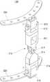
이하에서는 도 2 및 도 3을 참조하여 상기 제1 관절 부재(130)에 대해 자세히 설명하기로 한다. 참고로, 도 2는 도 1의 제1 관절 부재(130)의 조립 사시도이고, 도 3은 도 1의 제1 관절 부재(130)의 분리 사시도이다.Hereinafter, the first
도 2 및 도 3에 도시된 바와 같이, 상기 제1 관절 부재(130)는 몸체(210), 제1 하부 체결판(220), 및 제1 상부 체결판(230)을 포함할 수 있다.As shown in FIGS. 2 and 3, the first
상기 몸체(210)는 제1 몸체부(211), 제1 상부 브라켓(212), 제1 상부 회전체(213), 제2 몸체부(214), 제1 하부 브라켓(215), 제1 하부 회전체(216), 및 제1 힌지부(217)를 포함할 수 있다.The
상기 제1 몸체부(211)는 상기 몸체(210)의 상부를 이루는 구조체로서 사각형 모양으로 형성되며, 아울러 그 내부가 중공된 형태로 형성될 수 있다. 상기 제1 몸체부(211)는 그 일측에 상기 제1 힌지부(217)의 일부를 포함하여 구성될 수 있으며, 그 타측에는 상기 제1 상부 브라켓(212)이 결합될 수 있다.The
이때, 상기 제1 몸체부(211)와 상기 제1 상부 브라켓(212) 사이에는 도면에는 도시되지 않았지만, 상기 몸체(210)의 높낮이를 조절하기 위한 제1 높이 조절부(미도시)가 배치될 수 있다. 상기 제1 높이 조절부는 나사 형태로 형성될 수 있으며, 이에 한정되지 않고 다양한 방식의 높이 조절 장치, 예를 들면 구멍이 일정 간격으로 형성된 길이 조절 빔과 상기 길이 조절 빔의 체결 홀에 삽입되어 조절된 높이를 유지하는 체결핀으로 이루어진 높이 조절 장치로 형성될 수 있다.A first height adjusting unit (not shown) for adjusting the height of the
상기 제1 상부 브라켓(212)은 상기 제1 몸체부(211)의 상부에 배치될 수 있다. 이러한 제1 상부 브라켓(212)은 고정 나사(212a)에 의해 상기 제1 몸체부(211)의 상부에 체결될 수 있다.The first
상기 제1 상부 회전체(213)는 상기 제1 상부 체결판(230)과 결합되고, 힌지 결합 구조를 통해 상기 제1 상부 브라켓(212)과 연결될 수 있다. 여기서, 상기 힌지 결합 구조는 회전핀(212b)과 결합 나사(212c)로 이루어질 수 있다.The first upper
즉, 상기 제1 상부 회전체(213)는 상기 회전핀(212b)과 상기 결합 나사(212c)로 이루어진 힌지 결합 구조를 통해 상기 제1 상부 브라켓(212)과 체결됨으로써 상기 회전핀(212b)을 기준으로 회전할 수 있게 된다.That is, the first upper
상기 제1 상부 회전체(213)의 회전 동력은 상기 제1 상부 체결판(230)에 전달되어 상기 제1 상부 체결판(230)이 상기 회전핀(212b)를 기준으로 회전할 수 있게 하며, 이로써 상기 제1 관절 부재(130)에 기계적 유연함을 제공할 수 있다.The rotational power of the first upper
상기 제2 몸체부(214)는 상기 몸체(210)의 하부를 이루는 구조체로서 사다리꼴의 육각형 모양으로 형성될 수 있다. 상기 제2 몸체부(214)는 그 일측에 상기 제1 힌지부(217)의 일부를 포함하여 구성될 수 있으며, 그 타측에는 상기 제1 하부 브라켓(215)이 결합될 수 있다.The
이때, 상기 제2 몸체부(214)와 상기 제1 하부 브라켓(215) 사이에는 도면에는 도시되지 않았지만, 상기 몸체(210)의 높낮이를 조절하기 위한 제2 높이 조절부(미도시)가 배치될 수 있다.A second height adjusting unit (not shown) for adjusting the height of the
상기 제2 높이 조절부는 앞서 설명한 제1 높이 조절부와 동일한 나사 형태로 형성될 수 있으며, 이에 국한되지 않고 다양한 방식의 높이 조절 장치, 예를 들면 구멍이 일정 간격으로 형성된 길이 조절 빔과 상기 길이 조절 빔의 체결 홀에 삽입되어 조절된 높이를 유지하는 체결핀으로 이루어진 높이 조절 장치로 형성될 수 있다.The second height adjuster may be formed in the same shape as the first height adjuster described above. The height adjuster may include various types of height adjusters such as a length adjusting beam having holes formed at regular intervals, And a fixing pin inserted into the fastening hole of the beam to maintain the adjusted height.
상기 제1 하부 브라켓(215)은 상기 제2 몸체부(214)의 하부에 배치될 수 있다. 이러한 제1 하부 브라켓(215)은 고정 나사(215a)에 의해 상기 제2 몸체부(214)의 하부에 체결될 수 있다.The first
상기 제1 하부 회전체(216)는 상기 제1 하부 체결판(215)과 결합되고, 힌지 결합 구조를 통해 상기 제1 하부 브라켓(215)과 연결될 수 있다. 여기서, 상기 힌지 결합 구조는 회전핀(215b)과 결합 나사(215c)로 이루어질 수 있다.The first lower
즉, 상기 제1 하부 회전체(216)는 상기 회전핀(215b)과 상기 결합 나사(215c)로 이루어진 힌지 결합 구조를 통해 상기 제1 하부 브라켓(215)과 체결됨으로써 상기 회전핀(215b)을 기준으로 회전할 수 있게 된다.That is, the first lower
상기 제1 하부 회전체(216)의 회전 동력은 상기 제1 상부 체결판(230)에 전달되어 상기 제1 상부 체결판(230)이 상기 회전핀(215b)를 기준으로 회전할 수 있게 하며, 이로써 상기 제1 관절 부재(130)에 기계적 유연함을 제공할 수 있다. 특히, 상기 제1 하부 회전체(216)의 회전 동력과 함께 상기 제1 상부 회전체(213)의 회전 동력이 상기 제1 상부 체결판(230)에 전달되는 경우, 상기 제1 관절 부재(130)에는 더욱 많은 기계적 유연함을 제공할 수 있다.The rotational power of the first lower
상기 제1 힌지부(217)는 상기 제2 몸체부(214)를 기준으로 상기 제1 몸체부(211)가 좌우로 회동 가능하도록 상기 제1 몸체부(211)와 상기 제2 몸체부(214)를 연결할 수 있다.The
즉, 상기 제1 힌지부(217)는 상기 제1 및 제2 몸체부(211, 214)의 일부에 형성되어 체결핀(217a)을 통해 힌지 결합됨으로써, 상기 제2 몸체부(214)를 기준으로 상기 제1 몸체부(211)가 상기 제1 상부 회전체(213) 또는 상기 제1 하부 회전체(216)와 다른 방향(예: 90도)으로 회전할 수 있도록 한다. 이러한 제1 힌지부(217)의 회전 동력 역시 상기 제1 상부 체결판(230)에 전달되어 상기 제1 상부 체결판(230)이 좌우로 회전될 수 있도록 함으로써 상기 제1 관절 부재(130)에 더욱 많은 기계적 유연함을 제공할 수 있게 된다.That is, the
한편, 상기 제1 하부 체결판(220)은 상기 몸체(210)의 하부에 배치될 수 있다. 이를 위해, 상기 제1 하부 체결판(220)은 고정나사(220a, 220b)를 통해 상기 몸체(210)의 제1 하부 회전체(216)와 체결될 수 있다.Meanwhile, the first
또한, 상기 제1 하부 체결판(220)은 상기 로드 부재(120) 중 적어도 하나와 결합하여 상기 최상부의 링 부재(110)에 고정 배치될 수 있다. 이를 위해, 상기 제1 하부 체결판(220)에는 상기 로드 부재(120)와의 결합을 위한 복수의 홀(222)이 구비될 수 있다.The first
즉, 상기 제1 하부 체결판(220)은 상기 복수의 홀(222)을 통해 상기 최상부의 링 부재(110) 및 상기 로드 부재(120)와 체결됨으로써, 상기 제1 관절 부재(130)가 최상부의 링 부재(110) 일측에 고정 배치되도록 할 수 있다.That is, the first
이러한 제1 하부 체결판(220)은 상기 대상 골격에 대응되도록 호(arc) 형상으로 형성되는 것이 바람직하다.The first
상기 제1 상부 체결판(230)은 상기 몸체(210)의 상부에 배치될 수 있다. 이를 위해, 상기 제1 상부 체결판(230)은 고정나사(230a, 230b)를 통해 상기 몸체(210)의 제1 상부 회전체(213)와 체결될 수 있다.The first
상기 제1 상부 체결판(230)은 상기 제1 하부 체결판(220)과 대응되는 호(arc) 형상을 가지는 것이 바람직하며, 상기 가변 외 고정 장치(100)와 관련된 다른 장치(예: 보조기)의 확장 연결을 위한 복수의 홀(232)을 구비할 수 있다.The first
상기 제1 상부 체결판(230)은 상기 복수의 홀(232)을 통해 상기 다른 장치와 체결될 수 있는데, 예를 들면 상기 다른 장치에 구비된 홀들과 나사 결합을 통해 체결될 수 있다.The first
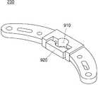
다른 실시예로서, 상기 제1 상부 체결판(230)은 도 9와 같은 형태로 형성될 수 있다. 즉, 상기 제1 상부 체결판(230)의 다른 실시예는 도 1 내지 도 3에 도시된 바와 같이 일정 반경의 홀이 다수 형성된 것과는 달리, 반경 조절이 가능한 중앙 홀(910)과 그 주변의 반경 조절이 불가한 나머지 홀들을 구비할 수 있다.As another example, the first
도 9에 도시된 바와 같이, 상기 제1 상부 체결판(230)의 다른 실시예는 중앙 홀(910)이 볼트 체결 조임부(920)와의 결합에 의해 반경 조절이 가능하도록 형성되기 때문에, 이 중앙 홀(910)에 봉을 넣고 상기 볼트 체결 조임부(920)를 조임으로써 다른 장치와 연결이 가능하게 된다. 따라서, 상기 제1 상부 체결판(230)의 다른 실시예는 상기 중앙 홀(910)의 반경 조절을 통해 상기 다른 장치의 확장 연결이 가능하도록 한다.9, since another embodiment of the first
다시 도 1을 참조하면, 상기 제2 관절 부재(140)는 상기 대상 골격에 해당하는 부위의 관절 움직임을 유도하기 위해 상기 최상부의 링 부재(110)의 타측에 배치된다.Referring again to FIG. 1, the second articulating
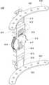
이하에서는 도 4 내지 도 8을 참조하여 상기 제2 관절 부재(140)에 대해 자세히 설명하기로 한다. 참고로, 도 4는 도 1의 제2 관절 부재(140)의 조립 사시도이고, 도 5는 도 1의 제2 관절 부재(140)의 측면도이며, 도 6은 도 1의 제2 관절 부재(140)의 분해 사시도이다. 그리고, 도 7은 도 4의 몸체(410)에 구비된 제2 힌지부를 설명하기 위해 도시한 사시도이며, 도 8은 도 4의 제2 상부 체결판이 제2 상부 브라켓 및 제2 상부 회전체와 체결되는 구조를 설명하기 위해 도시한 사시도이다.Hereinafter, the second
도 4 내지 도 8에 도시된 바와 같이, 상기 제2 관절 부재(140)는 몸체(410), 제2 하부 체결판(420), 및 제2 상부 체결판(430)을 포함할 수 있다.4 to 8, the second
상기 몸체(410)는 제3 몸체부(411), 제2 상부 브라켓(412), 제2 상부 회전체(413), 제4 몸체부(414), 제2 하부 브라켓(415), 제2 하부 회전체(416), 및 제2 힌지부(418, 419)를 포함할 수 있다.The
상기 제3 몸체부(411)는 상기 몸체(410)의 상부를 이루는 구조체로서 사각형 모양으로 형성되며, 중심부에 전후 방향으로 개방된 제1 수용부(411a), 및 상기 제3 몸체부(411)의 하단부로부터 하향으로 연장된 한 쌍의 연장편(417) 사이에 형성된 제2 수용부(411b)를 포함할 수 있다.The
이때, 상기 제3 몸체부(411)와 상기 제2 상부 브라켓(412) 사이에는 도면에는 도시되지 않았지만, 상기 몸체(410)의 높낮이를 조절하기 위한 제3 높이 조절부(미도시)가 배치될 수 있다. 상기 제3 높이 조절부는 나사 형태로 형성될 수 있으며, 이에 한정되지 않고 다양한 방식의 높이 조절 장치, 예를 들면 구멍이 일정 간격으로 형성된 길이 조절 빔과 상기 길이 조절 빔의 체결 홀에 삽입되어 조절된 높이를 유지하는 체결핀으로 이루어진 높이 조절 장치로 형성될 수 있다.Although not shown in the figure, a third height adjusting unit (not shown) for adjusting the height of the
상기 제2 상부 브라켓(412)은 상기 제3 몸체부(411)의 상부에 배치될 수 있다. 이러한 제2 상부 브라켓(412)은 고정 나사(412a)에 의해 상기 제 몸체부(411)의 상부에 체결될 수 있다.The second
상기 제2 상부 회전체(413)는 상기 제2 상부 체결판(430)과 결합되고, 힌지 결합 구조를 통해 상기 제2 상부 브라켓(412)과 연결될 수 있다. 여기서, 상기 힌지 결합 구조는 회전핀(412b)과 결합 나사(412c)로 이루어질 수 있다.The second upper
즉, 상기 제2 상부 회전체(413)는 상기 회전핀(412b)과 상기 결합 나사(412c)로 이루어진 힌지 결합 구조를 통해 상기 제2 상부 브라켓(412)과 체결됨으로써 상기 회전핀(412b)을 기준으로 회전할 수 있게 된다.That is, the second upper
상기 제2 상부 회전체(413)의 회전 동력은 상기 제2 상부 체결판(430)에 전달되어 상기 제2 상부 체결판(430)이 상기 회전핀(412b)를 기준으로 회전할 수 있게 하며, 이로써 상기 제2 관절 부재(140)에 기계적 유연함을 제공할 수 있다.The rotational power of the second upper
상기 제4 몸체부(414)는 상기 몸체(410)의 하부를 이루는 구조체로서 사다리꼴의 육각형 모양으로 형성될 수 있다. 상기 제4 몸체부(414)의 하측에는 상기 제2 하부 브라켓(415)이 결합될 수 있다.The
이때, 상기 제4 몸체부(414)와 상기 제2 하부 브라켓(415) 사이에는 도면에는 도시되지 않았지만, 상기 몸체(410)의 높낮이를 조절하기 위한 제4 높이 조절부(미도시)가 배치될 수 있다.A fourth height adjusting unit (not shown) for adjusting the height of the
상기 제4 높이 조절부는 앞서 설명한 제3 높이 조절부와 동일한 나사 형태로 형성될 수 있으며, 이에 국한되지 않고 다양한 방식의 높이 조절 장치, 예를 들면 구멍이 일정 간격으로 형성된 길이 조절 빔과 상기 길이 조절 빔의 체결 홀에 삽입되어 조절된 높이를 유지하는 체결핀으로 이루어진 높이 조절 장치로 형성될 수 있다.The fourth height adjuster may be formed in the same thread shape as the third height adjuster described above. The height adjuster may include various types of height adjusting devices, for example, a length adjusting beam having holes formed at regular intervals, And a fixing pin inserted into the fastening hole of the beam to maintain the adjusted height.
상기 제2 하부 브라켓(415)은 상기 제4 몸체부(414)의 하부에 배치될 수 있다. 이러한 제2 하부 브라켓(415)은 고정 나사(415a)에 의해 상기 제4 몸체부(414)의 하부에 체결될 수 있다.The second
상기 제2 하부 회전체(416)는 상기 제2 하부 체결판(420)과 결합되고, 힌지 결합 구조를 통해 상기 제2 하부 브라켓(415)과 연결될 수 있다. 여기서, 상기 힌지 결합 구조는 회전핀(415b)과 결합 나사(415c)로 이루어질 수 있다.The second lower rotating
즉, 상기 제2 하부 회전체(416)는 상기 회전핀(415b)과 상기 결합 나사(415c)로 이루어진 힌지 결합 구조를 통해 상기 제2 하부 브라켓(415)과 체결됨으로써 상기 회전핀(415b)을 기준으로 회전할 수 있게 된다.That is, the second lower rotating
상기 제2 하부 회전체(416)의 회전 동력은 상기 제2 상부 체결판(430)에 전달되어 상기 제2 상부 체결판(430)이 상기 회전핀(415b)를 기준으로 회전할 수 있게 하며, 이로써 상기 제2 관절 부재(140)에 기계적 유연함을 제공할 수 있다. 특히, 상기 제2 하부 회전체(416)의 회전 동력과 함께 상기 제2 상부 회전체(413)의 회전 동력이 상기 제2 상부 체결판(430)에 전달되는 경우, 상기 제2 관절 부재(140)에는 더욱 많은 기계적 유연함을 제공할 수 있다.The rotational power of the second lower rotating
상기 제2 힌지부(418, 419)는 상기 제4 몸체부(414)를 기준으로 상기 제3 몸체부(411)가 좌우로 회동 가능하도록 상기 제3 몸체부(411)와 상기 제4 몸체부(414)를 연결하는 역할을 한다. 이를 위해, 상기 제2 힌지부(418, 419)는 회전 나사(418) 및 회전축(419)을 포함할 수 있다.The
상기 회전 나사(418)는 외주면에 형성된 나사선을 구비하고, 회전 조작 가능하게 상기 제3 몸체부(411)의 제1 수용부(411a)에 수용될 수 있다. 상기 회전 나사(418)는 체결핀(418a)과 체결 나사(418b)에 의해 결합되어 상기 제1 수용부(411a)에 회전 조작 가능하도록 배치될 수 있다. 상기 회전 나사(418)의 회전 조작은 상기 체결 나사(418b)를 손으로 돌리는 동작에 의해 일 방향 또는 이와는 반대 방향으로 이루어질 수 있다.The
상기 회전축(419)은 상기 제3 몸체부(411)의 제2 수용부(411b)에 일부가 수용된 상태에서, 중심부의 구멍(419a)이 연결핀(419b)에 의해 상기 제3 몸체부(411)에 형성된 한 쌍의 연장편과 연결되고, 주변부 일측의 구멍(419c, 419d)이 체결핀(414a, 414b)에 의해 상기 제4 몸체부(414)에 고정될 수 있다.A
상기 회전축(419)은 상기 회전 나사(418)의 회전 조작에 따라 그 외주면에 형성된 톱니가 상기 회전 나사(418)의 나사선과 맞물려 상기 제3 몸체부(411)가 좌우로 회동 가능하도록 할 수 있다.The
여기서, 상기 연결핀(419b)은 내부가 중공(hollowness)된 형태로 이루어진 것이 바람직하다. 상기 연결핀(419b)은 본 발명의 일 실시예에 따른 가변 외 고정 장치(100)를 상기 대상 골격에 착용 시, 상기 연결핀(419b)의 중공된 부분을 통해 와이어 등을 통과시켜 가면서 신체의 어느 부분에 착용이 되고 있는지를 확인할 수 있도록 한다. 또한, 상기 대상 골격과 상기 가변 외 고정 장치(100) 간의 간격을 조정할 수 있도록 함으로써, 착용자가 상기 가변 외 고정 장치(100)를 상기 대상 골격에 꼭 맞게 착용할 수 있도록 도움을 줄 수 있다.Here, it is preferable that the
한편, 상기 제2 하부 체결판(420)은 상기 몸체(410)의 하부에 배치될 수 있다. 이를 위해, 상기 제2 하부 체결판(420)은 고정나사(420a, 420b)를 통해 상기 몸체(410)의 제2 하부 회전체(416)와 체결될 수 있다.Meanwhile, the second
또한, 상기 제2 하부 체결판(420)은 상기 로드 부재(120) 중 적어도 하나와 결합하여 상기 최상부의 링 부재(110)에 고정 배치될 수 있다. 이를 위해, 상기 제2 하부 체결판(420)에는 상기 로드 부재(120)와의 결합을 위한 복수의 홀(422)이 구비될 수 있다.In addition, the second
즉, 상기 제2 하부 체결판(420)은 상기 복수의 홀(422)을 통해 상기 최상부의 링 부재(110) 및 상기 로드 부재(120)와 체결됨으로써, 상기 제2 관절 부재(140)가 최상부의 링 부재(110) 타측에 고정 배치되도록 할 수 있다.That is, the second
이러한 제2 하부 체결판(420)은 상기 대상 골격에 대응되도록 호(arc) 형상으로 형성되는 것이 바람직하다.The second
상기 제2 상부 체결판(430)은 상기 몸체(410)의 상부에 배치될 수 있다. 이를 위해, 상기 제2 상부 체결판(430)은 고정나사(430a, 430b)를 통해 상기 몸체(410)의 제2 상부 회전체(413)와 체결될 수 있다.The second
상기 제2 상부 체결판(430)은 상기 제2 하부 체결판(420)과 대응되는 호(arc) 형상을 가지는 것이 바람직하며, 상기 가변 외 고정 장치(100)와 관련된 다른 장치(예: 보조기)의 확장 연결을 위한 복수의 홀(432)을 구비할 수 있다.The second
상기 제2 상부 체결판(430)은 상기 복수의 홀(432)을 통해 상기 다른 장치와 체결될 수 있는데, 예를 들면 상기 다른 장치에 구비된 홀들과 나사 결합을 통해 체결될 수 있다. 상기 제2 상부 체결판(430)은 도 9와 같은 다른 실시예의 형태로 형성될 수 있다
The second
이와 같이 본 발명의 일 실시예에서는 골절 및 연부조직의 상태에 따라 골격의 고정 위치를 자유롭게 선정하여 간편하게 설치하는 체외 고정 장치에 관절의 움직임을 유도하기 위해 관절 부재를 구비함으로써, 조기운동을 할 수 있도록 하며, 추가 설치 및 해체가 용이하고, 종래의 일리자로프 외고정장치에 설치 및 해체가 용이함과 아울러, 견고한 고정력을 가질 수 있도록 한다.As described above, according to one embodiment of the present invention, since the joint member is provided to guide the movement of the joint to the excretory fastening device for freely selecting and fixing the fixed position of the skeleton according to the state of fracture and soft tissue, Further, it is easy to install and disassemble, and it is easy to install and disassemble in a conventional Irida rope external fixation device, and also to have a firm fixing force.
따라서, 본 발명의 일 실시예에 의하면, 골절을 당한 환자의 체외에 원운동이 아닌 관절의 움직임을 정확하게 추종하여 조기운동을 할 수 있도록 하여 재활과 동시에 치료를 병행하도록 함으로써, 환자의 골절 통증 감소 및 조기 물리 치료를 가능하게 할 수 있다.
Therefore, according to the embodiment of the present invention, it is possible to perform early exercise by following the motion of the joint rather than the circular movement to the outside of the patient who has suffered a fracture, and to perform treatment simultaneously with rehabilitation, And early physical therapy.
지금까지 본 발명에 따른 구체적인 실시예에 관하여 설명하였으나, 본 발명의 범위에서 벗어나지 않는 한도 내에서는 여러 가지 변형이 가능함은 물론이다. 그러므로, 본 발명의 범위는 설명된 실시예에 국한되어 정해져서는 안 되며, 후술하는 특허 청구의 범위뿐 아니라 이 특허 청구의 범위와 균등한 것들에 의해 정해져야 한다.While the present invention has been described in connection with what is presently considered to be practical exemplary embodiments, it is to be understood that the invention is not limited to the disclosed embodiments. Therefore, the scope of the present invention should not be limited to the described embodiments, but should be determined by the scope of the appended claims and equivalents thereof.
이상과 같이 본 발명은 비록 한정된 실시예와 도면에 의해 설명되었으나, 본 발명은 상기의 실시예에 한정되는 것은 아니며, 이는 본 발명이 속하는 분야에서 통상의 지식을 가진 자라면 이러한 기재로부터 다양한 수정 및 변형이 가능하다. 따라서, 본 발명 사상은 아래에 기재된 특허청구범위에 의해서만 파악되어야 하고, 이의 균등 또는 등가적 변형 모두는 본 발명 사상의 범주에 속한다고 할 것이다.
While the present invention has been particularly shown and described with reference to exemplary embodiments thereof, it is to be understood that the invention is not limited to the disclosed exemplary embodiments, but, on the contrary, Modification is possible. Accordingly, the spirit of the present invention should be understood only in accordance with the following claims, and all equivalents or equivalent variations thereof are included in the scope of the present invention.
110: 링 부재
120: 로드 부재
130: 제1 관절 부재
140: 제2 관절 부재
210, 410: 몸체
211: 제1 몸체부
212: 제1 상부 브라켓
213: 제1 상부 회전체
214: 제2 몸체부
215: 제1 하부 브라켓
216: 제1 하부 회전체
220: 제1 하부 체결판
230: 제1 상부 체결판
411: 제3 몸체부
412: 제2 상부 브라켓
413: 제2 상부 회전체
414: 제4 몸체부
415: 제2 하부 브라켓
416: 제2 하부 회전체
417: 연장편
418: 회전 나사
419: 회전축
420: 제2 하부 체결판
430: 제2 상부 체결판110: ring member
120: rod member
130: first joint member
140: second joint member
210, 410: body
211: first body part
212: first upper bracket
213: first upper rotating body
214: second body portion
215: first lower bracket
216: first lower rotating body
220: first lower fastening plate
230: first upper fastening plate
411: Third body part
412: second upper bracket
413: second upper rotating body
414: fourth body part
415: second lower bracket
416: second lower rotating body
417: Extension piece
418: Rotary screw
419:
420: second lower fastening plate
430: second upper fastening plate
Claims (19)
Translated fromKorean상기 링 부재 각각의 상대 위치가 고정되도록 상기 링 부재 각각을 일정 각도의 등 간격으로 관통하여 배치되는 복수의 로드 부재; 및
상기 대상 골격에 해당하는 부위의 관절 움직임을 유도하기 위해 상기 복수의 링 부재 중 최상부 링 부재의 일측 및 타측에 각각 배치되는 제1 및 제2 관절 부재
를 포함하는 것을 특징으로 하는 가변 외 고정 장치.
A plurality of ring members arranged to penetrate the object skeleton in the longitudinal direction of the object skeleton;
A plurality of rod members arranged to penetrate each of the ring members at equal intervals of a predetermined angle so that the relative positions of the ring members are fixed; And
A first and a second joint members disposed on one side and the other side of the uppermost ring member, respectively, of the plurality of ring members for inducing joint movement of a site corresponding to the object skeleton;
Wherein the movable member is movable between a first position and a second position.
상기 복수의 링 부재 각각은
상기 복수의 로드 부재 각각과의 결합을 위한 복수의 홀을 구비하고, 상기 복수의 홀을 통해 너비 조절이 가능하게 결합되는 것을 특징으로 하는 가변 외 고정 장치.
The method according to claim 1,
Each of the plurality of ring members
And a plurality of holes for engagement with each of the plurality of rod members, and is adjustably adjustable in width through the plurality of holes.
상기 복수의 로드 부재 각각은
상기 복수의 링 부재 각각과 결합되는 부분의 하부에 형성되고, 잠금 및 잠금 해제 기능이 구비된 힌지 구조로 이루어져 상기 복수의 로드 부재 각각의 움직임을 조정하거나 조정 후 고정하는 힌지 조인트
를 포함하는 것을 특징으로 하는 가변 외 고정 장치.
The method according to claim 1,
Each of the plurality of rod members
A hinge joint formed at a lower portion of a portion coupled with each of the plurality of ring members and having a hinge structure having a lock and an unlock function to adjust or adjust the movement of each of the plurality of rod members,
Wherein the movable member is movable between a first position and a second position.
상기 제1 관절 부재는
몸체;
상기 몸체의 하부에 배치되되, 상기 로드 부재 중 적어도 하나와 결합하여 고정 배치되는 제1 하부 체결판; 및
상기 몸체의 상부에 배치되고, 상기 제1 하부 체결판과 대응되는 호(arc) 형상을 가지는 제1 상부 체결판
을 포함하는 것을 특징으로 하는 가변 외 고정 장치.
The method according to claim 1,
The first joint member
Body;
A first lower fastening plate disposed at a lower portion of the body, the first lower fastening plate being fixedly disposed in association with at least one of the rod members; And
A first upper fastening plate disposed on the upper portion of the body and having an arc shape corresponding to the first lower fastening plate,
And a movable member fixed to the movable member.
상기 제1 상부 체결판은
상기 가변 외 고정 장치와 관련된 다른 장치의 확장 연결을 위한 복수의 홀을 구비하고, 상기 복수의 홀을 통해 상기 다른 장치와 체결되는 것을 특징으로 하는 가변 외 고정 장치.
5. The method of claim 4,
The first upper fastening plate
And a plurality of holes for extended connection of another device associated with the variable external fixation device and fastened to the other device through the plurality of holes.
상기 복수의 홀 중 중앙 홀은
홀의 반경 조절이 가능하도록 볼트 체결 조임부와의 결합에 의해 형성되는 것을 특징으로 하는 가변 외 고정 장치.
6. The method of claim 5,
The center hole of the plurality of holes
And is formed by engagement with a bolt tightening portion so that the radius of the hole can be adjusted.
상기 몸체는
제1 몸체부;
상기 제1 몸체부의 하부에 배치되는 제2 몸체부; 및
상기 제2 몸체부를 기준으로 상기 제1 몸체부가 좌우로 회동 가능하도록 상기 제1 몸체부와 상기 제2 몸체부를 연결하는 제1 힌지부
를 포함하는 것을 특징으로 하는 가변 외 고정 장치.
5. The method of claim 4,
The body
A first body portion;
A second body portion disposed below the first body portion; And
And a first hinge portion connecting the first body portion and the second body portion so that the first body portion can be pivotally moved in a lateral direction with respect to the second body portion,
Wherein the movable member is movable between a first position and a second position.
상기 몸체는
상기 제1 몸체부의 상부에 배치되는 제1 상부 브라켓; 및
상기 제1 상부 체결판과 결합되고, 힌지 결합 구조를 통해 상기 제1 상부 브라켓과 연결되는 제1 상부 회전체
를 더 포함하는 것을 특징으로 하는 가변 외 고정 장치.
8. The method of claim 7,
The body
A first upper bracket disposed on the upper portion of the first body portion; And
A first upper rotating body coupled to the first upper locking plate and connected to the first upper bracket through a hinge-
Further comprising: an elastic member fixed to the housing;
상기 몸체는
상기 제1 몸체부와 상기 제1 상부 브라켓 사이에 배치되어 상기 몸체의 높낮이를 조절하는 제1 높이 조절부
를 더 포함하는 것을 특징으로 하는 가변 외 고정 장치.
9. The method of claim 8,
The body
A first height adjusting unit disposed between the first body and the first upper bracket for adjusting the height of the body,
Further comprising: an elastic member fixed to the housing;
상기 몸체는
상기 제2 몸체부의 하부에 배치되는 제1 하부 브라켓; 및
상기 제1 하부 체결판과 결합되고, 힌지 결합 구조를 통해 상기 제1 하부 브라켓과 연결되는 제1 하부 회전체
를 더 포함하는 것을 특징으로 하는 가변 외 고정 장치.
9. The method of claim 8,
The body
A first lower bracket disposed at a lower portion of the second body portion; And
And a first lower rotating body coupled to the first lower locking plate and connected to the first lower bracket through a hinge-
Further comprising: an elastic member fixed to the housing;
상기 몸체는
상기 제2 몸체부와 상기 제1 하부 브라켓 사이에 배치되어 상기 몸체의 높낮이를 조절하는 제2 높이 조절부
를 더 포함하는 것을 특징으로 하는 가변 외 고정 장치.
11. The method of claim 10,
The body
And a second height adjuster disposed between the second body and the first lower bracket for adjusting the height of the body,
Further comprising: an elastic member fixed to the housing;
상기 제2 관절 부재는
몸체;
상기 몸체의 하부에 배치되되, 상기 로드 부재 중 적어도 하나와 결합하여 고정 배치되는 제2 하부 체결판; 및
상기 몸체의 상부에 배치되고, 상기 제2 하부 체결판과 대응되는 호 형상을 가지는 제2 상부 체결판
을 포함하는 것을 특징으로 하는 가변 외 고정 장치.
The method according to claim 1,
The second articulating member
Body;
A second lower fastening plate disposed at a lower portion of the body, wherein the second lower fastening plate is fixedly connected to at least one of the rod members; And
A second upper fastening plate disposed on the upper portion of the body and having a arc shape corresponding to the second lower fastening plate,
And a movable member fixed to the movable member.
상기 몸체는
제3 몸체부;
상기 제3 몸체부의 하부에 배치되는 제4 몸체부; 및
상기 제4 몸체부를 기준으로 상기 제3 몸체부가 좌우로 회동 가능하도록 상기 제3 몸체부와 상기 제4 몸체부를 연결하는 제2 힌지부
를 포함하는 것을 특징으로 하는 가변 외 고정 장치.
13. The method of claim 12,
The body
A third body portion;
A fourth body portion disposed at a lower portion of the third body portion; And
And a second hinge portion connecting the third body portion and the fourth body portion to allow the third body portion to pivot left and right with reference to the fourth body portion,
Wherein the movable member is movable between a first position and a second position.
상기 제3 몸체부는
중심부에 전후 방향으로 개방된 제1 수용부; 및
하단부로부터 하향으로 연장된 한 쌍의 연장편 사이에 형성된 제2 수용부
를 포함하고,
상기 제2 힌지부는
외주면에 형성된 나사선을 구비하고, 회전 조작 가능하게 상기 제1 수용부에 수용되는 회전 나사; 및
상기 제2 수용부에 일부가 수용된 상태에서, 중심부가 연결핀에 의해 상기 한 쌍의 연장편과 연결되고, 주변부 일측이 상기 제4 몸체부에 고정되며, 상기 회전 나사의 회전 조작에 따라 외주면에 형성된 톱니가 상기 나사선과 맞물려 상기 제3 몸체부가 좌우로 회동 가능하도록 하는 회전축
을 포함하는 것을 특징으로 하는 가변 외 고정 장치.14. The method of claim 13,
The third body portion
A first receiving portion opened in the front and rear direction in the central portion; And
A second receiving portion formed between a pair of extending portions extending downward from the lower end portion,
Lt; / RTI >
The second hinge portion
A rotary screw having a thread formed on an outer circumferential surface thereof and accommodated in the first accommodating portion so as to be rotatable; And
The center portion is connected to the pair of extending pieces by the connecting pin while one side of the peripheral portion is fixed to the fourth body portion in a state where the second receiving portion is partially accommodated, And the formed tooth engages with the threaded portion so that the third body portion can be pivoted laterally,
And a movable member fixed to the movable member.
상기 연결핀은
내부가 중공(hollowness)된 형태로 이루어진 것을 특징으로 하는 가변 외 고정 장치.
15. The method of claim 14,
The connecting pin
And the inner portion is formed in a hollowed shape.
상기 몸체는
상기 제3 몸체부의 상부에 배치되는 제2 상부 브라켓; 및
상기 제2 상부 체결판과 결합되고, 힌지 결합 구조를 통해 상기 제2 상부 브라켓과 연결되는 제2 상부 회전체
를 더 포함하는 것을 특징으로 하는 가변 외 고정 장치.
14. The method of claim 13,
The body
A second upper bracket disposed on the third body part; And
A second upper bracket coupled to the second upper bracket and connected to the second upper bracket through a hinge connection structure,
Further comprising: an elastic member fixed to the housing;
상기 몸체는
상기 제3 몸체부와 상기 제2 상부 브라켓 사이에 배치되어 상기 몸체의 높낮이를 조절하는 제3 높이 조절부
를 더 포함하는 것을 특징으로 하는 가변 외 고정 장치.
17. The method of claim 16,
The body
And a third height adjuster disposed between the third body and the second upper bracket for adjusting the height of the body,
Further comprising: an elastic member fixed to the housing;
상기 몸체는
상기 제4 몸체부의 하부에 배치되는 제2 하부 브라켓; 및
상기 제2 하부 체결판과 결합되고, 힌지 결합 구조를 통해 상기 제2 하부 브라켓과 연결되는 제2 하부 회전체
를 더 포함하는 것을 특징으로 하는 가변 외 고정 장치.
17. The method of claim 16,
The body
A second lower bracket disposed under the fourth body part; And
A second lower rotating body coupled to the second lower locking plate and connected to the second lower bracket via a hinge coupling structure,
Further comprising: an elastic member fixed to the housing;
상기 몸체는
상기 제4 몸체부와 상기 제2 하부 브라켓 사이에 배치되어 상기 몸체의 높낮이를 조절하는 제4 높이 조절부
를 더 포함하는 것을 특징으로 하는 가변 외 고정 장치.19. The method of claim 18,
The body
And a fourth height adjuster disposed between the fourth body and the second lower bracket for adjusting the height of the body,
Further comprising: an elastic member fixed to the housing;
Priority Applications (1)
| Application Number | Priority Date | Filing Date | Title |
|---|---|---|---|
| KR20140130885AKR101501635B1 (en) | 2014-09-30 | 2014-09-30 | Variable external fixation device |
Applications Claiming Priority (1)
| Application Number | Priority Date | Filing Date | Title |
|---|---|---|---|
| KR20140130885AKR101501635B1 (en) | 2014-09-30 | 2014-09-30 | Variable external fixation device |
Publications (1)
| Publication Number | Publication Date |
|---|---|
| KR101501635B1true KR101501635B1 (en) | 2015-03-12 |
Family
ID=53027263
Family Applications (1)
| Application Number | Title | Priority Date | Filing Date |
|---|---|---|---|
| KR20140130885AActiveKR101501635B1 (en) | 2014-09-30 | 2014-09-30 | Variable external fixation device |
Country Status (1)
| Country | Link |
|---|---|
| KR (1) | KR101501635B1 (en) |
Cited By (4)
| Publication number | Priority date | Publication date | Assignee | Title |
|---|---|---|---|---|
| KR101657491B1 (en) | 2015-12-04 | 2016-09-19 | (주)올소테크 | Medical treatment for small bone fixation device |
| WO2017142148A1 (en)* | 2016-02-15 | 2017-08-24 | 경북대학교 산학협력단 | External fixation device having rotatable correction frame |
| US11272957B2 (en) | 2018-10-04 | 2022-03-15 | University Of Utah Research Foundation | Coupled torsional fixator and method of use |
| US12274475B2 (en) | 2018-10-04 | 2025-04-15 | Peter M. Stevens | Automated coupled torsional fixators and method of use |
Citations (4)
| Publication number | Priority date | Publication date | Assignee | Title |
|---|---|---|---|---|
| KR19980702664A (en)* | 1995-03-01 | 1998-08-05 | 존데이비드홉스 | Space frame |
| KR19990075902A (en)* | 1998-03-21 | 1999-10-15 | 한홍준 | Fracture fixation system |
| JP2004522536A (en)* | 2001-02-26 | 2004-07-29 | ガスダルストヴィニィ ウチリジデンイェ ロシイスキイ ナウチニイ チェントル ヴォスタノビテルナヤ トラフマトロギア イ オルトペジャ イメニ アカデミカ ゲ ア イリザロヴァ | Limb bone fixation device |
| US7226449B2 (en)* | 2000-05-09 | 2007-06-05 | Orthofix S.R.L. | Ring fixator |
- 2014
- 2014-09-30KRKR20140130885Apatent/KR101501635B1/enactiveActive
Patent Citations (4)
| Publication number | Priority date | Publication date | Assignee | Title |
|---|---|---|---|---|
| KR19980702664A (en)* | 1995-03-01 | 1998-08-05 | 존데이비드홉스 | Space frame |
| KR19990075902A (en)* | 1998-03-21 | 1999-10-15 | 한홍준 | Fracture fixation system |
| US7226449B2 (en)* | 2000-05-09 | 2007-06-05 | Orthofix S.R.L. | Ring fixator |
| JP2004522536A (en)* | 2001-02-26 | 2004-07-29 | ガスダルストヴィニィ ウチリジデンイェ ロシイスキイ ナウチニイ チェントル ヴォスタノビテルナヤ トラフマトロギア イ オルトペジャ イメニ アカデミカ ゲ ア イリザロヴァ | Limb bone fixation device |
Cited By (6)
| Publication number | Priority date | Publication date | Assignee | Title |
|---|---|---|---|---|
| KR101657491B1 (en) | 2015-12-04 | 2016-09-19 | (주)올소테크 | Medical treatment for small bone fixation device |
| WO2017142148A1 (en)* | 2016-02-15 | 2017-08-24 | 경북대학교 산학협력단 | External fixation device having rotatable correction frame |
| KR101780788B1 (en)* | 2016-02-15 | 2017-09-21 | 경북대학교 산학협력단 | An exterial fixator with a rotational correcting frame |
| US10898229B2 (en)* | 2016-02-15 | 2021-01-26 | Kyungpook National University Industry-Academic Cooperation Foundation | External fixator having rotatable bone reduction frame |
| US11272957B2 (en) | 2018-10-04 | 2022-03-15 | University Of Utah Research Foundation | Coupled torsional fixator and method of use |
| US12274475B2 (en) | 2018-10-04 | 2025-04-15 | Peter M. Stevens | Automated coupled torsional fixators and method of use |
Similar Documents
| Publication | Publication Date | Title |
|---|---|---|
| JP6103773B2 (en) | Orthopedic external fixator for elbow joint | |
| US8425512B2 (en) | Fixation device and multiple-axis joint for a fixation device | |
| US9717528B2 (en) | External fixator with Y strut | |
| KR101780788B1 (en) | An exterial fixator with a rotational correcting frame | |
| US20080021451A1 (en) | External Fixator | |
| KR101501635B1 (en) | Variable external fixation device | |
| JPH08510403A (en) | Orthopedic device, especially for the progressive correction of fractures | |
| BR112018015797B1 (en) | DYNAMIZATION SUPPORT | |
| US10993868B2 (en) | Dynamic foot plate | |
| CN105050515B (en) | Articulating devices for the wrist | |
| CN106361488B (en) | Fracture of distal radius wrist fixes protector | |
| CN103750936A (en) | Jacket inward abutting type fracture fixation support | |
| EP2967958B1 (en) | Dynamic footplate | |
| RU2352284C1 (en) | Device for treatment of difficult fractures of radial bone | |
| KR100595479B1 (en) | External fixation device for fractures | |
| JP4352112B2 (en) | Limb bone fixation device | |
| AU2020304950B2 (en) | Polyaxial strut for external fixation | |
| KR200301189Y1 (en) | External fixation device for fractures | |
| RU72397U1 (en) | MONOREPOSITION ROD COMPRESSION-DISTRACTION DEVICE FOR OSTEOSYNTHESIS OF EXTREMITIES | |
| JP2004522536A5 (en) | ||
| CN103800111A (en) | Inner sustaining type sleeve support for fracture fixation | |
| WO2013005130A1 (en) | Fixator for bone fractures | |
| CN103800112A (en) | Fracture inner sustaining fixing type sleeve support | |
| WO2016193154A1 (en) | External fixation system | |
| HK1186949B (en) | External orthopaedic fixator for the elbow joint |
Legal Events
| Date | Code | Title | Description |
|---|---|---|---|
| PA0109 | Patent application | Patent event code:PA01091R01D Comment text:Patent Application Patent event date:20140930 | |
| PA0201 | Request for examination | ||
| PA0302 | Request for accelerated examination | Patent event date:20141002 Patent event code:PA03022R01D Comment text:Request for Accelerated Examination Patent event date:20140930 Patent event code:PA03021R01I Comment text:Patent Application | |
| E701 | Decision to grant or registration of patent right | ||
| PE0701 | Decision of registration | Patent event code:PE07011S01D Comment text:Decision to Grant Registration Patent event date:20150303 | |
| GRNT | Written decision to grant | ||
| PR0701 | Registration of establishment | Comment text:Registration of Establishment Patent event date:20150305 Patent event code:PR07011E01D | |
| PR1002 | Payment of registration fee | Payment date:20150305 End annual number:3 Start annual number:1 | |
| PG1601 | Publication of registration | ||
| FPAY | Annual fee payment | Payment date:20180112 Year of fee payment:4 | |
| PR1001 | Payment of annual fee | Payment date:20180112 Start annual number:4 End annual number:4 | |
| FPAY | Annual fee payment | Payment date:20200203 Year of fee payment:6 | |
| PR1001 | Payment of annual fee | Payment date:20200203 Start annual number:6 End annual number:6 | |
| PR1001 | Payment of annual fee | Payment date:20210202 Start annual number:7 End annual number:7 | |
| PR1001 | Payment of annual fee | Payment date:20221226 Start annual number:9 End annual number:9 | |
| PR1001 | Payment of annual fee | Payment date:20231227 Start annual number:10 End annual number:10 | |
| PR1001 | Payment of annual fee | Payment date:20241223 Start annual number:11 End annual number:11 |