KR101501314B1 - Mimo detection method and system based on channel correlation - Google Patents
Mimo detection method and system based on channel correlationDownload PDFInfo
- Publication number
- KR101501314B1 KR101501314B1KR1020107025452AKR20107025452AKR101501314B1KR 101501314 B1KR101501314 B1KR 101501314B1KR 1020107025452 AKR1020107025452 AKR 1020107025452AKR 20107025452 AKR20107025452 AKR 20107025452AKR 101501314 B1KR101501314 B1KR 101501314B1
- Authority
- KR
- South Korea
- Prior art keywords
- correlation
- channel
- modulation symbols
- ofdm modulation
- channels
- Prior art date
- Legal status (The legal status is an assumption and is not a legal conclusion. Google has not performed a legal analysis and makes no representation as to the accuracy of the status listed.)
- Expired - Fee Related
Links
Images


Classifications
- H—ELECTRICITY
- H04—ELECTRIC COMMUNICATION TECHNIQUE
- H04L—TRANSMISSION OF DIGITAL INFORMATION, e.g. TELEGRAPHIC COMMUNICATION
- H04L27/00—Modulated-carrier systems
- H04L27/26—Systems using multi-frequency codes
- H04L27/2601—Multicarrier modulation systems
- H04L27/2647—Arrangements specific to the receiver only
- H04L27/2649—Demodulators
- H—ELECTRICITY
- H04—ELECTRIC COMMUNICATION TECHNIQUE
- H04B—TRANSMISSION
- H04B7/00—Radio transmission systems, i.e. using radiation field
- H04B7/02—Diversity systems; Multi-antenna system, i.e. transmission or reception using multiple antennas
- H04B7/04—Diversity systems; Multi-antenna system, i.e. transmission or reception using multiple antennas using two or more spaced independent antennas
- H04B7/0413—MIMO systems
- H—ELECTRICITY
- H04—ELECTRIC COMMUNICATION TECHNIQUE
- H04L—TRANSMISSION OF DIGITAL INFORMATION, e.g. TELEGRAPHIC COMMUNICATION
- H04L25/00—Baseband systems
- H04L25/02—Details ; arrangements for supplying electrical power along data transmission lines
- H04L25/0202—Channel estimation
- H04L25/0204—Channel estimation of multiple channels
- H—ELECTRICITY
- H04—ELECTRIC COMMUNICATION TECHNIQUE
- H04L—TRANSMISSION OF DIGITAL INFORMATION, e.g. TELEGRAPHIC COMMUNICATION
- H04L25/00—Baseband systems
- H04L25/02—Details ; arrangements for supplying electrical power along data transmission lines
- H04L25/0202—Channel estimation
- H04L25/0222—Estimation of channel variability, e.g. coherence bandwidth, coherence time, fading frequency
- H—ELECTRICITY
- H04—ELECTRIC COMMUNICATION TECHNIQUE
- H04L—TRANSMISSION OF DIGITAL INFORMATION, e.g. TELEGRAPHIC COMMUNICATION
- H04L5/00—Arrangements affording multiple use of the transmission path
- H04L5/0001—Arrangements for dividing the transmission path
- H04L5/0003—Two-dimensional division
- H04L5/0005—Time-frequency
- H04L5/0007—Time-frequency the frequencies being orthogonal, e.g. OFDM(A) or DMT
- H—ELECTRICITY
- H04—ELECTRIC COMMUNICATION TECHNIQUE
- H04B—TRANSMISSION
- H04B7/00—Radio transmission systems, i.e. using radiation field
- H04B7/02—Diversity systems; Multi-antenna system, i.e. transmission or reception using multiple antennas
- H04B7/04—Diversity systems; Multi-antenna system, i.e. transmission or reception using multiple antennas using two or more spaced independent antennas
- H04B7/08—Diversity systems; Multi-antenna system, i.e. transmission or reception using multiple antennas using two or more spaced independent antennas at the receiving station
- H04B7/0837—Diversity systems; Multi-antenna system, i.e. transmission or reception using multiple antennas using two or more spaced independent antennas at the receiving station using pre-detection combining
- H04B7/0842—Weighted combining
- H04B7/0848—Joint weighting
- H04B7/0854—Joint weighting using error minimizing algorithms, e.g. minimum mean squared error [MMSE], "cross-correlation" or matrix inversion
- H—ELECTRICITY
- H04—ELECTRIC COMMUNICATION TECHNIQUE
- H04J—MULTIPLEX COMMUNICATION
- H04J11/00—Orthogonal multiplex systems, e.g. using WALSH codes
- H04J11/0023—Interference mitigation or co-ordination
- H04J11/0026—Interference mitigation or co-ordination of multi-user interference
Landscapes
- Engineering & Computer Science (AREA)
- Signal Processing (AREA)
- Computer Networks & Wireless Communication (AREA)
- Power Engineering (AREA)
- Radio Transmission System (AREA)
Abstract
Translated fromKoreanDescription
Translated fromKorean본 발명은 다중-입력 다중-출력(MIMO) 통신 시스템에 관한 것으로, 특히 현존하거나 장래의 정보 전송 시스템에서 MIMO를 검출하기 위한 MIMO 시스템의 수신기에 적용되는 채널 상관에 기반한 MIMO 검출 방법 및 시스템에 관한 것이다.The present invention relates to a multi-input multiple-output (MIMO) communication system, and more particularly to a channel correlation-based MIMO detection method and system applied to a receiver of a MIMO system for detecting MIMO in an existing or future information transmission system will be.
일반적으로 MIMO 시스템에서의 수신기는 상대 기기가 전송하는 신호를 검출하는 경우, 먼저 채널들을 추정하게 된다. 이러한 추정된 채널들에 따라서 최소 자승 오차-정렬 간섭 제거(Minimum Mean Squared Error-Ordered Successive Interference Cancellation, MMSE-OSIC) 또는 최소 자승 오차-정렬 간섭 제거-다중 후보(Minimum Mean Squared Error-Ordered Successive Interference Cancellation-Multiple Candidate, MMSE-OSIC2) 방법으로, 데이터가 채널들에 대하여 개별적으로 검출된다. 즉, 하나의 채널이 다른 채널과 독립적으로 존재하게 된다.In general, when a receiver in a MIMO system detects a signal transmitted from an external device, it first estimates channels. Order MMSE-OSIC or a minimum mean square error-order interference cancellation (MMSE) message according to the estimated channels. -Multiple Candidate, MMSE-OSIC2 ) method, the data is detected separately for the channels. That is, one channel is independent of other channels.
전송된 데이터 x1 및 x2가 검출되는 2×4 MIMO 검출 프로세스를 예로 든다. 종래의 검출 방법에 따르면, x1을 검출하고 그런 다음 x1의 검출 결과에 따라서 x2를 검출할 필요가 있다. MMSE-OSIC 검출과 MMSE-OSIC2 검출 사이의 차이로는 x1의 MMSE-OSIC 검출을 실시하고 있을 때에는 단 하나의 가능성만이 판단되고, 반면 x1의 MMSE-OSIC2 검출을 실시하고 있을 때에는 몇몇 후보들이 판단된다는 점이다. 후보들의 수가 증가하고 있는 상황에서, 검출 성능은 개선되는 반면에 검출의 복잡성도 따라서 증가하게 된다. 후보의 개수가 1과 동일할 경우에, 두 개의 검출 방법은 정확히 동일하게 된다.A 2x4 MIMO detection process in which transmitted data x1 and x2 are detected will be exemplified. According to the conventional detection method, it is necessary to detect x1 and then detect x2 in accordance with the detection result of x1. As the difference between the MMSE-OSIC detection and MMSE-OSIC2 detected several candidates when there subjected to a single potential only is determined, MMSE-OSIC2 detects, while x1 when there subjected to a MMSE-OSIC detection of x1 . In a situation where the number of candidates is increasing, the detection performance improves while the detection complexity increases accordingly. If the number of candidates is equal to 1, then the two detection methods are exactly the same.
이하 본 설명에서 언급하는 용어 "상관 시간(correlation time)"은 특정 시간 간격을 말하는 것으로, 이 시간 내에서는 두 개의 도달 신호들의 진폭이 매우 상관되어 있음을 나타낸다. 용어 "상관 대역폭(correlation bandwidth)"은 특정 주파수 범위를 말하는 것으로, 이 주파수 범위 내에서는 두 개의 주파수 컴포넌트들의 진폭이 매우 상관되어 있음을 나타낸다.The term "correlation time " referred to in this description refers to a specific time interval in which the amplitude of the two arriving signals is highly correlated. The term " correlation bandwidth "refers to a particular frequency range within which the amplitudes of the two frequency components are highly correlated.
현존하는 기술에 있어서, 검출에 대한 방법에서는 채널에 대해 개별적으로 실시되기 때문에,In existing techniques, because they are implemented separately for the channel in the method for detection,
채널 상관의 특성은 데이터 검출에 이용되지 않는 문제점이 있다. 그리고, 노이즈 버스트(noise burst) 환경하에서, 추정 편차(estimation deviation)에 있어서의 큰 버스트가 무작위로 발생할 가능성이 있다. 이러한 경우, 만일 신호 검출이 큰 추정 편차를 갖는 채널에 대하여 실시되면, 큰 오차가 발생하거나 또는 신호 검출에 있어서 BER(Bit Error Rate)이 증가하게 된다.The characteristic of channel correlation is not used for data detection. And, under a noise burst environment, there is a possibility that a large burst in estimation deviation occurs randomly. In this case, if the signal detection is performed for a channel having a large estimation error, a large error occurs or a BER (Bit Error Rate) increases in signal detection.
그리고, 현존하는 기술에 있어서, 특정 BER 성능을 획득하기 위해서는, MMSE-OSIC2에서의 후보의 수에 직접적으로 비례하는 검출 방법에 대한 하드웨어 자원이 더욱더 요구되는 문제점이 있다.In addition, in order to obtain a specific BER performance in existing technologies, a hardware resource for a detection method directly proportional to the number of candidates in the MMSE-OSIC2 is further required.
따라서, 본 발명은 종래 기술에서 발생하는 상술한 단점들을 해결하기 위하여 이루어졌으며, 본 발명은 현존하거나 장래의 정보 전송 시스템에서 MIMO를 검출하기 위한 MIMO 시스템의 수신기에 적용되는 채널 상관에 기반한 MIMO 검출 방법 및 시스템을 제공한다.SUMMARY OF THE INVENTION Accordingly, the present invention has been made to solve the above-mentioned problems occurring in the prior art, and it is an object of the present invention to provide a MIMO detection method based on channel correlation applied to a receiver of a MIMO system for detecting MIMO in an existing or future information transmission system And a system.
본 발명의 일 실시예에서 제안하는 방법은; OFDM(Orthogonal Frequency Division Multiplexing) 심볼 검출 방법에 있어서, 다수의 전송 안테나들로부터 전송된 OFDM 변조 심볼들을 수신하는 과정과, 상기 다수의 전송 안테나들로부터 상관 시간(correlation time) 및 상관 대역폭(correlation bandwidth) 중 적어도 하나에 관한 정보를 수신하는 과정과, 상기 다수의 전송 안테나들에 대한 복수의 채널들 각각에서 채널 추정을 수행하고, 상기 상관 시간 및 상관 대역폭 중 적어도 하나에 관한 정보에 따라서 각의 채널 추정 결과에 대해 평활화 프로세싱(smoothing processing)을 수행하여, 각 채널들의 채널 추정 평균들을 획득하는 과정과, 상기 채널 추정 평균들을 이용하여 상기 수신된 OFDM 변조 심볼들에 대한신호 검출을 수행하는 과정을 포함함을 특징으로 한다.A method proposed in an embodiment of the present invention comprises: A method of detecting an OFDM symbol, the method comprising: receiving OFDM modulation symbols transmitted from a plurality of transmit antennas; receiving a correlation time and a correlation bandwidth from the plurality of transmit antennas; And performing channel estimation on each of a plurality of channels for the plurality of transmit antennas and performing channel estimation based on information on at least one of the correlation time and the correlation bandwidth, Performing smoothing processing on the result to obtain channel estimation averages of the respective channels and performing signal detection on the received OFDM modulation symbols using the channel estimation averages .
본 발명의 일 실시예에서 제안하는 장치는; OFDM(Orthogonal Frequency Division Multiplexing) 심볼 검출 장치에 있어서, 다수의 전송 안테나들로부터 전송된 OFDM 변조 심볼들을 수신하고, 상기 다수의 전송 안테나들로부터 상관 시간(correlation time) 및 상관 대역폭(correlation bandwidth) 중 적어도 하나에 관한 정보를 수신하는 수신기와, 상기 다수의 전송 안테나들에 대한 복수의 채널들 각각에서 채널 추정을 수행하고, 상기 상관 시간 및 상관 대역폭 중 적어도 하나에 관한 정보에 따라서 각의 채널 추정 결과에 대해 평활화 프로세싱(smoothing processing)을 수행하여, 각 채널들의 채널 추정 평균들을 획득하고, 상기 채널 추정 평균들을 이용하여 상기 수신된 OFDM 변조 심볼들에 대한신호 검출을 수행하는 프로세서를 포함함을 특징으로 한다.An apparatus proposed in an embodiment of the present invention comprises: 1. An OFDM symbol detection apparatus comprising: a receiver for receiving OFDM modulation symbols transmitted from a plurality of transmit antennas and receiving at least one of a correlation time and a correlation bandwidth from the plurality of transmit antennas, And a receiver for performing channel estimation on each of a plurality of channels for the plurality of transmit antennas and for performing channel estimation on each channel estimation result according to information on at least one of the correlation time and the correlation bandwidth, And performing a smoothing processing on the received OFDM modulation symbols to obtain channel estimation averages of the respective channels and performing signal detection on the received OFDM modulation symbols using the channel estimation averages .
본 발명에 따른 방법에 의하면, 채널들의 시간 상관 및 주파수 상관이 고려e됨으로써,According to the method of the present invention, time correlation and frequency correlation of channels are considered,
1. 동일한 복잡성으로, 종래의 MMSE-OSIC 기반의 방법 보다 우수한 성능을가지며, 하드웨어 자원이 축소되기 때문에,1. With the same complexity, superior performance over the conventional MMSE-OSIC based method, and reduced hardware resources,
MMSE-OSIC2 기반의 방법에 근접할 수 있는 효과가 있다.There is an effect that can approach the method based on MMSE-OSIC2 .
도 1은 MIMO 동작 환경을 나타내는 개략도.
도 2는 MIMO 전송 플로우의 일례를 나타내는 도면.
도 3은 본 발명에 따른 MIMO 수신단(MIMO receiving end)을 나타내는 개략도.
도 4는 본 발명에 따른 MIMO 검출부를 나타내는 블록도.
도 5는 본 발명에 따른 MIMO 신호 검출 방법을 나타내는 플로우.
도 6은 본 발명에 따른 평활 필터(smoothing filter)를 나타내는 도면.
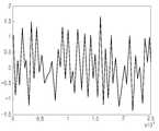
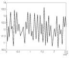
도 7은 이상적인 레일리(Raleigh) 채널을 나타내는 도면.
도 8은 간섭을 갖는 레일리 채널을 나타내는 도면.
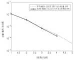
도 9는 평균 오차 확률(average error probability)의 시뮬레이션 결과를 나타내는 도면.
도 10은 평균 오차 확률의 시뮬레이션 결과를 나타내는 도면.1 is a schematic diagram showing a MIMO operating environment;
2 is a diagram showing an example of a MIMO transmission flow;
3 is a schematic diagram illustrating a MIMO receiving end according to the present invention;
4 is a block diagram illustrating a MIMO detector according to the present invention;
5 is a flowchart illustrating a MIMO signal detection method according to the present invention.
6 is a view showing a smoothing filter according to the present invention.
7 shows an ideal Raleigh channel;
8 shows a Rayleigh channel with interference;
9 is a diagram showing a simulation result of an average error probability;
10 is a diagram showing a simulation result of an average error probability;
아래에서는 첨부한 도면을 참조하여 본 발명이 속하는 기술 분야에서 통상의 지식을 가진 자가 용이하게 실시할 수 있도록 본 발명의 실시예를 상세히 설명한다. 그러나 본 발명은 여러 가지 상이한 형태로 구현될 수 있으며 여기에서 설명하는 실시예에 한정되지 않는다. 그리고 도면에서 본 발명을 명확하게 설명하기 위해서 설명과 관계없는 부분은 생략하였으며, 명세서 전체를 통하여 유사한 부분에 대해서는 유사한 도면 부호를 붙였다. 본 발명을 명확하게 설명하기 위하여, 현존하는 MMSE-OSIC2 방법을 소개한다.Hereinafter, embodiments of the present invention will be described in detail with reference to the accompanying drawings, which will be readily apparent to those skilled in the art. The present invention may, however, be embodied in many different forms and should not be construed as limited to the embodiments set forth herein. In order to clearly illustrate the present invention, parts not related to the description are omitted, and similar parts are denoted by like reference characters throughout the specification. To clearly illustrate the present invention, an existing MMSE-OSIC2 method is introduced.
NT×NR MIMO 시스템이 다음과 같이 표현된다고 하자:Let NT × NR MIMO systems be expressed as:

여기서,
MIMO 채널 응답은 다음과 같이 표현된다.The MIMO channel response is expressed as follows.

여기서,


본 실시예에서, 전송 신호

몇몇 채널의 MMSE 가중치 매트릭스는 다음과 같다:The MMSE weighting matrix for some channels is:


여기서

다음에는, 현존하는 MMSE-OSIC2 방법을 설명하기 위하여 4×4 MIMO 시스템을 예로 든다.Next, a 4x4 MIMO system is illustrated to illustrate the existing MMSE-OSIC2 method.
스텝 1: 정렬된 시퀀스 h1, h2, ..., h4를 획득하기 위해 1, 2, ... , NT (4×4 MIMO 시스템에 대하여 NT=4) 채널을 정렬한다. 채널들은 복소 채널(complex channel)이고 벡터의 형태를 취하기 때문에, 정렬 프로세스는 이러한 벡터들의 놈(norm)을 비교함으로써 실시된다. 여기서, h1은 네 개의 채널에서의 최대 놈을 나타내고, hNT는 네 개의 채널에서의 최소 놈을 나타낸다.Step 1:
스텝 2: x1의 가능한 세트로부터 M개의 후보 심볼을 선택한다. 이 스텝은 표 1에 도시된 바와 같이 실행될 수 있다. 표 1에서 h1은 스텝 1을 통하여 획득된 것을 나타낸 것이며, MMSE-OSIC2에서의 스텝 2이다.Step 2: Select M candidate symbols from the possible set of x1. This step can be carried out as shown in Table 1. < tb >< TABLE > In Table 1, h1 will shown that obtained through the
스텝 3: x1 및 x2의 가능한 세트로부터 M개의 후보 심볼을 선택한다. 이 스텝은 표 2에 도시된 바와 같이 실행될 수 있으며, MMSE-OSIC2에서의 스텝 4이다.Step 3: Select M candidate symbols from the possible set of x1 and x2. This step can be performed as shown in Table 2, and
스텝 4: x1, x2 및 x3의 가능한 세트로부터 M개의 후보 심볼을 선택한다. 이 스텝은 표 3에 도시된 바와 같이 실행될 수 있으며, MMSE-OSIC2에서의 스텝 4이다.Step 4: Select M candidate symbols from the possible set of x1, x2 and x3. This step can be performed as shown in Table 3, a
스텝 5: x1, x2, x3 및 x4의 가능한 세트로부터 M개의 후보 심볼을 선택한다. 이 스텝은 표 4에 도시된 바와 같이 실행될 수 있다.Step 5: Select M candidate symbols from the possible set of x1, x2, x3 and x4. This step can be performed as shown in Table 4. [
다음의 표에 나타낸 슬라이서(slicer) 프로세싱은 성좌를 나타내는 심볼들로부터 가장 근접한 성좌 지점들을 결정하고 출력하기 위한 프로세싱이다. 예를 들어, 16 QAM의 경우, 16 QAM-변조 신호를 나타내는 16개의 레벨로부터의 가장 근접한 성좌 지점들이 결정되고 출력된다. 64 QAM의 경우, 64 QAM-변조 신호를 나타내는 64 레벨로부터 가장 근접한 성좌 지점들을 결정하고 출력한다. 다음의 표에 나타낸 정렬 프로세싱은 |C| 인스턴스들을 오름 차순으로 정렬하기 위한 프로세싱이며; 16 QAM의 경우에는, |C|=16이 되고, 64 QAM의 경우에는, |C|=64가 된다.The slicer processing shown in the following table is processing for determining and outputting nearest constellation points from the symbols representing constellations. For example, in the case of 16 QAM, the closest constellation points from the 16 levels representing the 16 QAM-modulated signal are determined and output. For 64 QAM, determine and output closest constellation points from 64 levels representing 64 QAM-modulated signals. The alignment processing shown in the following table is | C | Processing for sorting instances in ascending order; In the case of 16 QAM, | C | = 16, and in the case of 64 QAM, | C | = 64.
아래 <표 1>은 MMSE-OSIC2에서의 스텝 2를 나타낸 것이고, <표 2>는 MMSE-OSIC2에서의 스텝 3을 나타낸 것이고, <표 3> 및 <표 4>는 MMSE-OSIC2에서의 스텝 4를 나타낸 것이다.Table 1 below shows Step2 in MMSE-OSIC2 , Table 2 shows


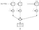
본 발명에 따른 수신단(receiving end)에 적용된 신호 검출 방법을 도 3 내지 도 6을 참조하여 설명한다. 도 3은 본 발명에 따른 MIMO 수신단을 나타내는 개략도이다. 도 4는 본 발명에 따른 MIMO 검출부를 나타내는 블록도이다. 도 5는 본 발명에 따른 MIMO 신호 검출 방법을 나타내는 플로우이다. 도 6은 본 발명에 따른 평활 필터의 구조를 나타내는 도면이다.A signal detection method applied to a receiving end according to the present invention will be described with reference to FIG. 3 to FIG. 3 is a schematic diagram showing a MIMO receiving terminal according to the present invention. 4 is a block diagram illustrating a MIMO detector according to the present invention. 5 is a flowchart illustrating a MIMO signal detection method according to the present invention. 6 is a view showing a structure of a smoothing filter according to the present invention.
본 발명은 상술한 스텝 1에서의 동작에 관련된다. 도 3에 나타낸 바와 같이, 본 발명에 따른 수신단(300)은 전송단으로부터 다중 전송 안테나에 의해 전송된 관련 정보 및 OFDM(Orthogonal Frequency Division Multiplexing) 심볼 데이터를 수신하는 MIMO 수신부(301)를 포함한다; 또한, 수신단(300)dms 수신된 관련 정보에 따라서 수신된 데이터 중에서 전송단으로부터의 신호들을 검출하는 MMSE-OSIC 신호 검출부(303); 및 전송단의 변조 데이터를 획득하기 위하여 검출된 신호를 복조하는 QAM 복조부(305)를 포함할 수도 있다.The present invention relates to the operation in
본 발명에 따른 MIMO 신호 검출 방법은 주로 신호 검출부(303)에서 실시된다. 도 4에 나타낸 바와 같이, 신호 검출부(303)는 슬라이딩 평균화 필터(3031), 적응 채널 간섭 제거기(3033) 및 검출부(3035)를 포함할 수도 있다. 본 발명에 따른 신호 검출 방법을 도 5 및 도 6을 참조하여 이하에 설명한다.The MIMO signal detection method according to the present invention is mainly performed in the
먼저, 스텝 501에서, 수신단(300)에서의 수신부(301)는 전송단으로부터 OFDM 심볼들과 관련 정보를 수신한다. 여기서, 관련 정보는, 예를 들어, 상관 서브-캐리어들의 개수(m)와 같은 상관 시간 정보와, 예를 들어, 상관 OFDM 심볼 개수와 같은 상관 대역폭 정보를 포함한다. 콘텍스트(context)에서의 상관 시간은 특정 시간 간격을 말하는 것으로, 이 시간 간격 내에서 두 개의 도달 신호의 진폭이 매우 상관되어 있는 것을 나타내며, 상관 대역폭은 특정 주파수 범위를 말하는 것으로, 이 주파수 범위 내에서 두 개의 주파수 컴포넌트의 진폭이 매우 상관되어 있는 것을 나타낸다.First, in
다음으로, 신호 검출부(303)는 상관 서브-캐리어의 수신 개수(m)와 상관 OFDM 심볼의 수신 개수(n)에 따라서 채널 세기(strength)를 서로 다른 수신 안테나로부터 결정한다. 채널 세기를 결정하는 접근 방법으로는 먼저 네 개의 채널 h1, h2, h3 및 h4(열 벡터)의 놈을 각각 계산하고, 이 네 개의 놈을 비교하는 방법이 있다. 만일 어떤 열 벡터의 놈이 더 크게 되면, 해당 채널이 더 큰 세기를 갖는 것이고, 그렇지 않을 경우에는, 세기가 작은 것이다. 수신단에서, 수신된 신호들은 이 결정에 따라서 처리된다.Next, the
상세하게는, 스텝 502에서, 채널들의 세기를 결정하기 위하여, 상관 서브-캐리어의 수신 개수(m)와 상관 OFDM 심볼의 수신 개수(n)에 따라서 슬라이딩 평균화 필터(3031)에서 수신 채널에 대하여 슬라이딩 평균화 프로세스가 실행된다. 본질적으로, 슬라이딩 평균화 필터는 평활 필터링 기능을 갖는 유한 임펄스 응답(finite impulse response) 필터가 된다. 여기서, 채널 상관에 따라 결정되는 (m*n)는 탭 계수(tap coefficient)의 개수를 나타낸다. 평활 프로세싱 후에, 천이하는 큰 간섭의 충격을 수신기는 피할 수 없게 된다. 즉, 강한 간섭 신호가 자동적으로 억제될 수 있다. 슬라이딩 평균환 필터를 도 6에 도시한다.Sliding averaging
도 6에 나타낸 바와 같이, (m*n)은 슬라이딩 평균화 필터의 탭 계수의 개수, 즉, 필터의 길이를 나타낸다. D는 시프트 레지스터를 나타낸다. 채널 놈(들)은 슬라이들 필터에 입력된다. 클록의 상승 에지에서, 채널 놈은 필터 내로 이동된다. (m*n)개의 채널 임펄스 응답 값들은 각각의 채널 임펄스 응답 값이 합해져서 하나로 합산된다. 이 합산 값은 (m*n)으로 나눗셈하여 슬라이딩 평균환 필터로부터 출력된다. 즉, (m*n)개의 채널들이 평균화된다. 슬라이딩 평균화 프로세스 후에, 강한 간섭 컴포넌트들이 채널에 대하여 억제된다. 만일 m=1인 경우, 슬라이딩 평균화 프로세스의 길이(length)는 n이 되고, 즉, 슬라이딩 평균화 프로세스는 상관 시간 내에서만 실행되고; 만일 n=1인 경우, 슬라이딩 평균화 프로세스의 길이가 m이 되고, 즉, 슬라이딩 평균환 프로세스는 상관 대역폭 내에서만 실행되고; 만일 m과 n이 모두 1보다 크게 될 경우, 슬라이딩 평균 프로세스는 상관 시간 및 상관 대역폭 내에서 m*n개의 채널에 대해 실행됨에 유의해야 한다.As shown in Fig. 6, (m * n) represents the number of tap coefficients of the sliding averaging filter, that is, the length of the filter. D represents a shift register. The channel norm (s) are input to the slice filter. At the rising edge of the clock, the channel norm is shifted into the filter. (m * n) channel impulse response values are summed into one by summing the respective channel impulse response values. This sum value is output from the sliding average conversion filter by dividing by (m * n). That is, (m * n) channels are averaged. After the sliding averaging process, strong interference components are suppressed for the channel. If m = 1, the length of the sliding averaging process is n, i.e., the sliding averaging process is performed only within the correlation time; If n = 1, then the length of the sliding averaging process is m, i. E., The sliding average rotation process is performed only within the coherent bandwidth; Note that if m and n are both greater than one, the sliding average process is performed for m * n channels within the correlation time and the correlation bandwidth.
슬라이딩 평균화가 이루어지는 채널들 사이에는 적응적 선택이 행하여져서 이들은 슬라이딩 평균화를 거치지 않게 된다. h1avg는 슬라이딩 평균화 프로세싱된 채널 매트릭스의 첫 번째 열을 나타내고, h2avg는 슬라이딩 평균화 프로세싱된 채널 매트릭스의 두 번째 열을 나타내며, h1 및 h2는 슬라이딩 평균화되지 않은 채널 매트릭스의 첫 번째 및 두 번째 열을 각각 나타낸다. 여기서, 적응적 선택은 채널에서 강한 간섭이 존재하는지의 여부를 결정하는 것을 말한다. 만일 존재할 경우, 슬라이딩 평균화가 실행되어 강한 간섭을 제거하게 되며, 만일 존재하지 않을 경우, 간섭이 없는 일반적인 채널이 선택되어 진다.Adaptive selection is performed between the channels on which the sliding averaging is performed, so that the sliding averaging is not performed.
여기서, 시간 도메인 또는 주파수 도메인 또는 이 둘에서의 슬라이딩 평균화 중 하나가 슬라이딩 평균화 필터에 의해 적용될 수 있다. 적응적으로 조정된 윈도(window)에 의거한 필터링 방식은 슬라이딩 평균화 필터(3031)에 의해 적용된다. 윈도의 크기는 채널 패이딩 레이트(channel fading rate)에 따라서 적응적으로 조정된다. 만일 채널이 급속하게 패이딩될 경우, 슬라이딩 윈도의 크기는 더 작아지도록 조정되어야 한다. 채널이 느리게 패이딩될 경우, 슬라이딩 윈도의 크기는 더 커지도록 조정되어야 한다. 채널 세기 결정 프로세스 동안에, 현재의 OFDDM 심볼에서의 채널뿐만 아니라 상관 시간 내에서의 1~n 개의 OFDM 심볼에서의 채널도 고려된다. 한편으로, 현재 OFDM 서브-캐리어 내에서 채널들뿐만 아니라 상관 대역폭 내에서의 1~m 개의 OFDM 서브-캐리어에서의 채널들도 고려된다.Here, one of the sliding averaging in the time domain or the frequency domain or both can be applied by the sliding averaging filter. A filtering scheme based on an adaptively adjusted window is applied by the sliding averaging
그런 다음, 적응 채널 간섭 추정 프로세스가 슬라이딩 평균화될 채널 값들에 대하여 실행된다. 상세하게는, 스텝 503에서, h1avg가 h2avg와 비교된다. 만일 h1avg가 h2avg보다 더 큰 경우, 방법은 스텝 504로 이동하여 h1과 h2를 비교한다. 만일 h1이 h2보다 더 큰 경우, 방법은 스텝 507로 진행하고, h1과 h2는 변화없이 유지되어, 이어지는 스텝들(즉, 표 1 내지 4에 열거된 동작들)이 진행된다. 반면에, 만일 h1이 h2보다 더 크지 않을 경우, 방법은 스텝 506으로 진행하고, h2는 h2avg로 대체되고, h1은 변화없이 유지되어, 이어지는 단계들이 진행된다.An adaptive channel interference estimation process is then performed on the channel values to be slid averaged. More specifically, in
만일 h1avg가 h2avg보다 더 크지 않고 스텝 505에서 h1이 h2보다 더 큰 것으로 판단되는 경우, 방법은 스텝 509로 진행하고, h1은 h1avg로 대체되고 h2는 변화없이 유지되어, 이어지는 스텝들(즉, 표 1 내지 4에 열거된 동작들)이 진행된다. 반면에, h1이 h2보다 더 크지 않을 경우, 방법은 스텝 508로 진행하고, h1및 h2는 모두 변화없이 유지되어, 이어지는 스텝들이 진행된다.Ten thousand and one h1avg is not greater than h2avg is maintained if in
본 발명에 따른 바람직한 실시예에서의 시스템 파라미터들을 표 5에 열거한다.The system parameters in the preferred embodiment according to the present invention are listed in Table 5.
본 발명에서 획득된 성능 개선을 입증하기 위하여, 컴퓨터 시뮬레이션 결과를 제공한다. 이 시뮬레이션에서는, 독립적이지만 동일 분포를 갖는 레일리 패이딩 채널을 시뮬레이션하였다. 도 7 및 도 8은 이상적인 레일리 채널과 간섭이 있는 레일리 채널을 도시한다. 도플러 주파수 시프트(doppler frequency shift)는 30Hz에서 이루어지는 것으로 가정하고 이는 해당 이동 속도로 해석되어 질 수 있다. 시뮬레이션 결과를 도 9 및 도 10에 도시한다.To demonstrate the performance improvements obtained in the present invention, computer simulation results are provided. In this simulation, Rayleigh fading channels are simulated that are independent but have the same distribution. Figures 7 and 8 show Rayleigh channels with interference with the ideal Rayleigh channel. It is assumed that the Doppler frequency shift occurs at 30 Hz, which can be interpreted as the corresponding moving speed. The simulation results are shown in FIGS. 9 and 10. FIG.
도 9 및 도 10으로부터, 종래 MIMO 전송 및 수신 방법에 비하여 본 발명의 따른 방법이 우수한 성능을 갖는 것을 확실히 알 수 있다. 낮은 SNR(signal-to-noise ratio)의 경우, 본 발명에 따른 방법에서 1dB의 성능 향상이 얻어질 수 있다. 1dB의 성능 이득은 MIMO 수신기에서 중대한 개선임을 이해하여야 한다.It can be clearly seen from FIGS. 9 and 10 that the method according to the present invention has superior performance over the conventional MIMO transmission and reception method. For a low signal-to-noise ratio (SNR), a performance improvement of 1 dB in the method according to the invention can be obtained. It should be understood that the 1 dB performance gain is a significant improvement in the MIMO receiver.
본 발명은 바람직한 실시예를 통하여 나타내고 설명되었지만, 첨부된 청구범위에 의해 정의된 바와 같은 본 발명의 취지 및 범위를 벗어나지 않는 한 변형 및 변경이 이루어질 수 있음이 당업자에게는 명백할 것이다.While the invention has been shown and described with reference to a preferred embodiment thereof, it will be apparent to those skilled in the art that modifications and variations may be made without departing from the spirit and scope of the invention as defined by the appended claims.
301: MIMO 수신부303: MMSE-OSIC 검출부
305: QAM 복조부301: MIMO receiving unit 303: MMSE-OSIC detecting unit
305: QAM demodulator
Claims (20)
Translated fromKorean다수의 전송 안테나들로부터 전송된 OFDM 변조 심볼들을 수신하는 과정과,
상기 다수의 전송 안테나들로부터 상관 시간(correlation time) 및 상관 대역폭(correlation bandwidth) 중 적어도 하나에 관한 정보를 수신하는 과정과,
상기 다수의 전송 안테나들에 대한 복수의 채널들 각각에서 채널 추정을 수행하고, 상기 상관 시간 및 상관 대역폭 중 적어도 하나에 관한 정보에 따라서 각의 채널 추정 결과에 대해 평활화 프로세싱(smoothing processing)을 수행하여, 각 채널들의 채널 추정 평균들을 획득하는 과정과,
상기 채널 추정 평균들을 이용하여 상기 수신된 OFDM 변조 심볼들에 대한신호 검출을 수행하는 과정을 포함하는 OFDM 심볼 검출 방법.
An Orthogonal Frequency Division Multiplexing (OFDM) symbol detection method,
Comprising: receiving OFDM modulation symbols transmitted from a plurality of transmit antennas;
Receiving information on at least one of a correlation time and a correlation bandwidth from the plurality of transmit antennas;
Performs channel estimation on each of a plurality of channels for the plurality of transmission antennas and performs smoothing processing on each channel estimation result according to information on at least one of the correlation time and the correlation bandwidth Obtaining channel estimation averages of the respective channels,
And performing signal detection on the received OFDM modulation symbols using the channel estimation averages.
상기 상관 시간 내의 OFDM 변조 심볼들의 개수를 포함하고, 상기 상관 대역폭에 관한 정보는 상기 상관 대역폭 내에서의 OFDM 서브-캐리어들의 개수를 포함하는 OFDM 심볼 검출 방법.
2. The method of claim 1, wherein the information about the correlation time comprises:
The number of OFDM modulation symbols in the correlation time, and the information on the correlation bandwidth includes the number of OFDM sub-carriers within the correlation bandwidth.
상기 복수의 채널들의 개수는 상기 OFDM 서브-캐리어의 개수를 상기 OFDM 변조 심볼들의 개수와 곱하여 획득되는 값임을 특징으로 하는 OFDM 심볼 검출 방법.
3. The method of claim 2, wherein the performing smoothing processing comprises: performing a sliding averaging process on values representing the plurality of channels in at least one of a time domain and a frequency domain to calculate channel estimation averages for the plurality of channels And acquiring,
Wherein the number of the plurality of channels is a value obtained by multiplying the number of OFDM sub-carriers by the number of OFDM modulation symbols.
4. The method of claim 3, wherein the size of the window for the sliding averaging process is adaptively adjusted to increase the size of the window when the channel fading rate of the channel is reduced.
4. The method of claim 3, wherein an adaptive channel interference cancellation process is performed on the channel estimation averages for the sliding averaging process.
상기 슬라이딩 평균화 프로세스에 따른 값들인 제1 평균 채널 상관값(h1avg)과 제2 평균 채널 상관값(h2avg)을 비교하는 과정과,
제1 채널 상관값(h1)과 제2 채널 상관값(h2)을 비교하는 과정과,
상기 비교 결과들에 따라서 상기 수신된 OFDM 변조 심볼들을 처리하는 과정을 포함하는 OFDM 심볼 검출 방법.
6. The method of claim 5, wherein the adaptive channel interference cancellation process comprises:
Comparing a first average channel correlation value h1avg and a second average channel correlation value h2avg , which are values according to the sliding averaging process,
Comparing the first channel correlation value h1 with the second channel correlation value h2 ;
And processing the received OFDM modulation symbols according to the comparison results.
h1avg가 h2avg보다 크고, h1이 h2보다 큰 경우, 상기 수신된 OFDM 변조 심볼들은 h1과 h2를 이용하여 처리됨을 특징으로 하는 OFDM 심볼 검출 방법.
The method according to claim 6,
wherein h1avg isgreater than h2avg and h1 is greater than h2 , the received OFDM modulation symbols are processed using h1 and h2 .
h1avg가 h2avg보다 크고, h1이 h2보다 크지 않을 경우, 상기 수신된 OFDM 변조 심볼들은 h1과 h2avg를 이용하여 처리됨을 특징으로 하는 OFDM 심볼 검출 방법.
The method according to claim 6,
wherein h1avg isgreater than h2avg and h1 is not greater than h2 , the received OFDM modulation symbols are processed using h1 and h2avg .
h1avg가 h2avg보다 크지 않고, h1이 h2보다 클 경우, 상기 수신된 OFDM 변조 심볼들은 h1avg와 h2를 이용하여 처리됨을 특징으로 하는 OFDM 심볼 검출 방법.
The method according to claim 6,
wherein h1avg is not greater than h2avg and h1 is greater than h2 , the received OFDM modulation symbols are processed using h1avg and h2 .
h1avg가 h2avg보다 크지 않고, h1이 h2보다 크지 않을 경우, 상기 수신된 OFDM 변조 심볼들은 h1과 h2를 이용하여 처리됨을 특징으로 하는 OFDM 심볼 검출 방법.
The method according to claim 6,
wherein if havg is not greater than h2avg and h1 is not greater than h2 then the received OFDM modulation symbols are processed using h1 and h2 .
다수의 전송 안테나들로부터 전송된 OFDM 변조 심볼들을 수신하고, 상기 다수의 전송 안테나들로부터 상관 시간(correlation time) 및 상관 대역폭(correlation bandwidth) 중 적어도 하나에 관한 정보를 수신하는 수신기와,
상기 다수의 전송 안테나들에 대한 복수의 채널들 각각에서 채널 추정을 수행하고, 상기 상관 시간 및 상관 대역폭 중 적어도 하나에 관한 정보에 따라서 각의 채널 추정 결과에 대해 평활화 프로세싱(smoothing processing)을 수행하여, 각 채널들의 채널 추정 평균들을 획득하고, 상기 채널 추정 평균들을 이용하여 상기 수신된 OFDM 변조 심볼들에 대한신호 검출을 수행하는 프로세서를 포함하는 OFDM 심볼 검출 장치.
An Orthogonal Frequency Division Multiplexing (OFDM) symbol detection apparatus,
A receiver for receiving OFDM modulation symbols transmitted from a plurality of transmit antennas and receiving information about at least one of a correlation time and a correlation bandwidth from the plurality of transmit antennas;
Performs channel estimation on each of a plurality of channels for the plurality of transmission antennas and performs smoothing processing on each channel estimation result according to information on at least one of the correlation time and the correlation bandwidth And a processor for obtaining channel estimation averages of the respective channels and performing signal detection on the received OFDM modulation symbols using the channel estimation averages.
상기 상관 시간 내의 OFDM 변조 심볼들의 개수를 포함하고, 상기 상관 대역폭에 관한 정보는 상기 상관 대역폭 내에서의 OFDM 서브-캐리어들의 개수를 포함하는 OFDM 심볼 검출 장치.
12. The method of claim 11, wherein the information about the correlation time comprises:
The number of OFDM modulation symbols in the correlation time, and the information on the correlation bandwidth includes the number of OFDM sub-carriers within the correlation bandwidth.
시간 도메인 및 주파수 도메인 중 적어도 하나에서 상기 복수의 채널들을 나타내는 값들에 대하여 슬라이딩 평균화 프로세스를 수행하여 상기 복수의 채널들에 대한 채널 추정 평균들을 획득하며,
상기 복수의 채널들의 개수는 상기 OFDM 서브-캐리어의 개수를 상기 OFDM 변조 심볼들의 개수와 곱하여 획득되는 값임을 특징으로 하는 OFDM 심볼 검출 장치.
13. The apparatus of claim 12, wherein the processor comprises:
Performing a sliding averaging process on values representing the plurality of channels in at least one of a time domain and a frequency domain to obtain channel estimation averages for the plurality of channels,
Wherein the number of the plurality of channels is a value obtained by multiplying the number of OFDM sub-carriers by the number of OFDM modulation symbols.
14. The apparatus of claim 13, wherein the size of the window for the sliding averaging process is adaptively adjusted to increase the size of the window when the channel fading rate of the channel is reduced.
14. The OFDM symbol detection apparatus of claim 13, wherein an adaptive channel interference cancellation process is performed on the channel estimation averages for the sliding averaging process.
상기 슬라이딩 평균화 프로세스에 따른 값들인 제1 평균 채널 상관값(h1avg)과 제2 평균 채널 상관값(h2avg)을 비교하는 동작과,
제1 채널 상관값(h1)과 제2 채널 상관값(h2)을 비교하는 동작과,
상기 비교 결과들에 따라서 상기 수신된 OFDM 변조 심볼들을 처리하는 동작을 포함하는 OFDM 심볼 검출 장치.
16. The method of claim 15, wherein the adaptive channel interference cancellation process comprises:
And the operation of comparing the values, which are a first average channel correlation values (h1avg) and the second average channel correlation values (h2avg) according to the sliding averaging process,
Comparing the first channel correlation value (h1 ) and the second channel correlation value (h2 )
And processing the received OFDM modulation symbols according to the comparison results.
h1avg가 h2avg보다 크고, h1이 h2보다 큰 경우, 상기 수신된 OFDM 변조 심볼들은 h1과 h2를 이용하여 처리됨을 특징으로 하는 OFDM 심볼 검출 장치.
17. The method of claim 16,
If h is greater than1avg2avg h, h1 is greater than h2, OFDM modulation symbols are the received OFDM symbol detection device according to claim the processed using h1 and h2.
h1avg가 h2avg보다 크고, h1이 h2보다 크지 않을 경우, 상기 수신된 OFDM 변조 심볼들은 h1과 h2avg를 이용하여 처리됨을 특징으로 하는 OFDM 심볼 검출 장치.
17. The method of claim 16,
h when1avg is large, than h1 h2avg not greater than h2, OFDM symbol detection unit, characterized by processed by the received OFDM modulation symbols using the h1 and h2avg.
h1avg가 h2avg보다 크지 않고, h1이 h2보다 클 경우, 상기 수신된 OFDM 변조 심볼들은 h1avg와 h2를 이용하여 처리됨을 특징으로 하는 OFDM 심볼 검출 장치.
17. The method of claim 16,
If h is not larger than1avg2avg h, h1 is greater than h2, OFDM modulation symbols are the received OFDM symbol detection device characterized by using the processed1avg h and2 h.
h1avg가 h2avg보다 크지 않고, h1이 h2보다 크지 않을 경우, 상기 수신된 OFDM 변조 심볼들은 h1과 h2를 이용하여 처리됨을 특징으로 하는 OFDM 심볼 검출 장치.17. The method of claim 16,
If h is not larger than1avg2avg h, h1 is not greater than h2, OFDM symbol detection unit, characterized by processed by the received OFDM modulation symbols using the h1 and h2.
Applications Claiming Priority (3)
| Application Number | Priority Date | Filing Date | Title |
|---|---|---|---|
| CN2008100971626ACN101588335B (en) | 2008-05-19 | 2008-05-19 | Multiple input multiple output (MIMO) detecting method and MIMO detecting system utilizing correlation of signal channels |
| CN200810097162.6 | 2008-05-19 | ||
| PCT/KR2009/002461WO2009142407A2 (en) | 2008-05-19 | 2009-05-11 | Mimo detection method and system based on channel correlation |
Publications (2)
| Publication Number | Publication Date |
|---|---|
| KR20110008222A KR20110008222A (en) | 2011-01-26 |
| KR101501314B1true KR101501314B1 (en) | 2015-03-10 |
Family
ID=41340659
Family Applications (1)
| Application Number | Title | Priority Date | Filing Date |
|---|---|---|---|
| KR1020107025452AExpired - Fee RelatedKR101501314B1 (en) | 2008-05-19 | 2009-05-11 | Mimo detection method and system based on channel correlation |
Country Status (5)
| Country | Link |
|---|---|
| US (1) | US8532216B2 (en) |
| EP (1) | EP2283625A4 (en) |
| KR (1) | KR101501314B1 (en) |
| CN (1) | CN101588335B (en) |
| WO (1) | WO2009142407A2 (en) |
Families Citing this family (11)
| Publication number | Priority date | Publication date | Assignee | Title |
|---|---|---|---|---|
| CN101729208B (en)* | 2009-12-31 | 2013-06-05 | 中兴通讯股份有限公司 | Method and device for filtering channel quality indicator (CQI) |
| CN102148779B (en)* | 2011-03-21 | 2013-07-24 | 电信科学技术研究院 | Method and device for detecting signals |
| CN102164105B (en)* | 2011-05-09 | 2014-05-07 | 东南大学 | Adaptive receiving method for multi-antenna orthogonal frequency division multiplexing system |
| US9584347B2 (en)* | 2013-05-31 | 2017-02-28 | Silicon Laboratories Inc. | Methods and systems for rapid detection of digital radio signals |
| CN107453850B (en)* | 2016-05-30 | 2020-10-20 | 普天信息技术有限公司 | A kind of detection method of physical uplink control channel |
| CN105827335B (en)* | 2016-06-07 | 2018-06-29 | 北京邮电大学 | A kind of antenna number determines method and device |
| US10312977B2 (en) | 2017-05-08 | 2019-06-04 | Nxp Usa, Inc. | Complexity reduction for receiver decoding |
| CN107257253B (en)* | 2017-05-16 | 2020-06-16 | 哈尔滨工程大学 | Interference elimination method based on antenna selection and antenna variable length coding |
| KR102149611B1 (en)* | 2019-08-26 | 2020-08-28 | 한국교통대학교산학협력단 | Apparatus for MMSE channel estimation based Multi stage in OFDM system |
| CN111610359B (en)* | 2020-05-29 | 2021-05-14 | 上海挚达科技发展有限公司 | Filtering method for controlling voltage acquisition of guide circuit by charging pile |
| EP4236099A1 (en) | 2022-02-24 | 2023-08-30 | Samsung Electronics Co., Ltd. | Apparatus and method for channel sounding |
Citations (3)
| Publication number | Priority date | Publication date | Assignee | Title |
|---|---|---|---|---|
| KR20050075242A (en)* | 2004-01-16 | 2005-07-20 | 삼성전자주식회사 | Pilot channel-based channel estimation method for mc-cdma system using frequency interleaving |
| US20050195734A1 (en)* | 2004-02-20 | 2005-09-08 | Kabushiki Kaisha Toshiba | Transmission signals, methods and apparatus |
| US20060153144A1 (en)* | 2005-01-11 | 2006-07-13 | Samsung Electronics Co., Ltd. | Pilot-based channel estimation method for MC-CDMA system |
Family Cites Families (9)
| Publication number | Priority date | Publication date | Assignee | Title |
|---|---|---|---|---|
| US20030012308A1 (en)* | 2001-06-13 | 2003-01-16 | Sampath Hemanth T. | Adaptive channel estimation for wireless systems |
| US7349667B2 (en)* | 2001-10-19 | 2008-03-25 | Texas Instruments Incorporated | Simplified noise estimation and/or beamforming for wireless communications |
| US6563885B1 (en)* | 2001-10-24 | 2003-05-13 | Texas Instruments Incorporated | Decimated noise estimation and/or beamforming for wireless communications |
| JP3914203B2 (en)* | 2002-01-10 | 2007-05-16 | 富士通株式会社 | Pilot multiplexing method and OFDM receiving method in OFDM system |
| US7433433B2 (en)* | 2003-11-13 | 2008-10-07 | Telefonaktiebolaget L M Ericsson (Publ) | Channel estimation by adaptive interpolation |
| US7848463B2 (en)* | 2005-04-07 | 2010-12-07 | Qualcomm Incorporated | Adaptive time-filtering for channel estimation in OFDM system |
| CN1917497B (en)* | 2006-09-08 | 2010-05-12 | 清华大学 | A method for multiple-input multiple-output OFDM link adaptation based on capacity |
| KR100909553B1 (en)* | 2006-11-27 | 2009-07-27 | 삼성전자주식회사 | Method and apparatus for MMS receiver adapting channel environment using multiple receive antennas |
| CN101601199B (en)* | 2007-12-28 | 2013-04-17 | 日本电气株式会社 | Signal processing and method for multi-sector wireless communication system |
- 2008
- 2008-05-19CNCN2008100971626Apatent/CN101588335B/ennot_activeExpired - Fee Related
- 2009
- 2009-05-11EPEP09750729.7Apatent/EP2283625A4/ennot_activeWithdrawn
- 2009-05-11USUS12/993,752patent/US8532216B2/ennot_activeExpired - Fee Related
- 2009-05-11KRKR1020107025452Apatent/KR101501314B1/ennot_activeExpired - Fee Related
- 2009-05-11WOPCT/KR2009/002461patent/WO2009142407A2/ennot_activeCeased
Patent Citations (4)
| Publication number | Priority date | Publication date | Assignee | Title |
|---|---|---|---|---|
| KR20050075242A (en)* | 2004-01-16 | 2005-07-20 | 삼성전자주식회사 | Pilot channel-based channel estimation method for mc-cdma system using frequency interleaving |
| US20050195734A1 (en)* | 2004-02-20 | 2005-09-08 | Kabushiki Kaisha Toshiba | Transmission signals, methods and apparatus |
| US20060153144A1 (en)* | 2005-01-11 | 2006-07-13 | Samsung Electronics Co., Ltd. | Pilot-based channel estimation method for MC-CDMA system |
| KR20060082228A (en)* | 2005-01-11 | 2006-07-18 | 삼성전자주식회사 | Pilot-based Channel Estimation Method for Multicarrier Code Division Multiple Access Systems |
Also Published As
| Publication number | Publication date |
|---|---|
| CN101588335B (en) | 2012-07-04 |
| WO2009142407A2 (en) | 2009-11-26 |
| WO2009142407A3 (en) | 2010-02-11 |
| CN101588335A (en) | 2009-11-25 |
| EP2283625A2 (en) | 2011-02-16 |
| EP2283625A4 (en) | 2016-07-13 |
| KR20110008222A (en) | 2011-01-26 |
| US20110069776A1 (en) | 2011-03-24 |
| US8532216B2 (en) | 2013-09-10 |
Similar Documents
| Publication | Publication Date | Title |
|---|---|---|
| KR101501314B1 (en) | Mimo detection method and system based on channel correlation | |
| US7209433B2 (en) | Channel estimation and compensation techniques for use in frequency division multiplexed systems | |
| US8306160B2 (en) | Synchronization circuit and synchronization method, wireless communication device and wireless communication method, and computer program | |
| US7957474B2 (en) | Robust detection of packet types | |
| KR101400852B1 (en) | Apparatus and method for cancelling of interference in multi-antenna system | |
| JP5053378B2 (en) | Equalization structure and equalization method | |
| US8446993B2 (en) | Receiving apparatus and method for receiving signals in a wireless communication system with improved equalization performance | |
| US8565295B1 (en) | Low-complexity channel noise reduction method and apparatus for multi-carrier mode in wireless LANS | |
| JP5053377B2 (en) | Equalization structure and equalization method | |
| US7656940B2 (en) | Equalizer and equalizing method | |
| KR101043698B1 (en) | Signal Detection Device and Method in Spatial Multiplexing System | |
| US20070116157A1 (en) | Signal decoding apparatus, signal decoding method, program, and information record medium | |
| JP5047289B2 (en) | Equalization structure and equalization method | |
| KR101492641B1 (en) | Channel estimation and compensation method and its receiver | |
| WO2008025394A1 (en) | Equalizing structure and equalizing method | |
| Soman et al. | Improved DFT-based channel estimation for spatial modulated orthogonal frequency division multiplexing systems | |
| KR100647079B1 (en) | Discrete Fourier Transform-based Channel Estimation Method for Frequency-Division Wireless Modem | |
| JP2006173764A (en) | Multi-carrier signal demodulation circuit and multi-carrier signal demodulation method | |
| KR101679429B1 (en) | Adaptive OSIC (ordered successive interference cancellation)-SD(sphere decoder) decoder and decoding method using the same | |
| JP2002247011A (en) | Receiver for space division multiplex communication | |
| JP2008092227A (en) | Wireless communication device | |
| KR101408866B1 (en) | Apparatus and method for signal detection in multiple input multiple output system of single carrier frequency division access | |
| CN119276324A (en) | Low-precision quantized MIMO-OTFS signal detection method based on serial interference cancellation | |
| JP2007208750A (en) | Receiver | |
| KR20120140524A (en) | Mimo-ofdm system with signal space diversity apparatus and method for transmitting data in the same, and apparatus and method for receiving data in the same |
Legal Events
| Date | Code | Title | Description |
|---|---|---|---|
| PA0105 | International application | St.27 status event code:A-0-1-A10-A15-nap-PA0105 | |
| PG1501 | Laying open of application | St.27 status event code:A-1-1-Q10-Q12-nap-PG1501 | |
| R18-X000 | Changes to party contact information recorded | St.27 status event code:A-3-3-R10-R18-oth-X000 | |
| A201 | Request for examination | ||
| P11-X000 | Amendment of application requested | St.27 status event code:A-2-2-P10-P11-nap-X000 | |
| P13-X000 | Application amended | St.27 status event code:A-2-2-P10-P13-nap-X000 | |
| PA0201 | Request for examination | St.27 status event code:A-1-2-D10-D11-exm-PA0201 | |
| R18-X000 | Changes to party contact information recorded | St.27 status event code:A-3-3-R10-R18-oth-X000 | |
| E701 | Decision to grant or registration of patent right | ||
| PE0701 | Decision of registration | St.27 status event code:A-1-2-D10-D22-exm-PE0701 | |
| GRNT | Written decision to grant | ||
| PR0701 | Registration of establishment | St.27 status event code:A-2-4-F10-F11-exm-PR0701 | |
| PR1002 | Payment of registration fee | St.27 status event code:A-2-2-U10-U12-oth-PR1002 Fee payment year number:1 | |
| PG1601 | Publication of registration | St.27 status event code:A-4-4-Q10-Q13-nap-PG1601 | |
| R18-X000 | Changes to party contact information recorded | St.27 status event code:A-5-5-R10-R18-oth-X000 | |
| LAPS | Lapse due to unpaid annual fee | ||
| PC1903 | Unpaid annual fee | St.27 status event code:A-4-4-U10-U13-oth-PC1903 Not in force date:20180305 Payment event data comment text:Termination Category : DEFAULT_OF_REGISTRATION_FEE | |
| PC1903 | Unpaid annual fee | St.27 status event code:N-4-6-H10-H13-oth-PC1903 Ip right cessation event data comment text:Termination Category : DEFAULT_OF_REGISTRATION_FEE Not in force date:20180305 | |
| P22-X000 | Classification modified | St.27 status event code:A-4-4-P10-P22-nap-X000 |