KR101498537B1 - Multi-charging apparatus for electronic equipment - Google Patents
Multi-charging apparatus for electronic equipmentDownload PDFInfo
- Publication number
- KR101498537B1 KR101498537B1KR20140005005AKR20140005005AKR101498537B1KR 101498537 B1KR101498537 B1KR 101498537B1KR 20140005005 AKR20140005005 AKR 20140005005AKR 20140005005 AKR20140005005 AKR 20140005005AKR 101498537 B1KR101498537 B1KR 101498537B1
- Authority
- KR
- South Korea
- Prior art keywords
- charging
- electronic device
- housing
- main body
- charging port
- Prior art date
- Legal status (The legal status is an assumption and is not a legal conclusion. Google has not performed a legal analysis and makes no representation as to the accuracy of the status listed.)
- Expired - Fee Related
Links
Images


Classifications
- H—ELECTRICITY
- H02—GENERATION; CONVERSION OR DISTRIBUTION OF ELECTRIC POWER
- H02J—CIRCUIT ARRANGEMENTS OR SYSTEMS FOR SUPPLYING OR DISTRIBUTING ELECTRIC POWER; SYSTEMS FOR STORING ELECTRIC ENERGY
- H02J7/00—Circuit arrangements for charging or depolarising batteries or for supplying loads from batteries
- H02J7/0042—Circuit arrangements for charging or depolarising batteries or for supplying loads from batteries characterised by the mechanical construction
- H02J7/0044—Circuit arrangements for charging or depolarising batteries or for supplying loads from batteries characterised by the mechanical construction specially adapted for holding portable devices containing batteries
- H—ELECTRICITY
- H02—GENERATION; CONVERSION OR DISTRIBUTION OF ELECTRIC POWER
- H02J—CIRCUIT ARRANGEMENTS OR SYSTEMS FOR SUPPLYING OR DISTRIBUTING ELECTRIC POWER; SYSTEMS FOR STORING ELECTRIC ENERGY
- H02J7/00—Circuit arrangements for charging or depolarising batteries or for supplying loads from batteries
- H02J7/0013—Circuit arrangements for charging or depolarising batteries or for supplying loads from batteries acting upon several batteries simultaneously or sequentially
- H—ELECTRICITY
- H02—GENERATION; CONVERSION OR DISTRIBUTION OF ELECTRIC POWER
- H02J—CIRCUIT ARRANGEMENTS OR SYSTEMS FOR SUPPLYING OR DISTRIBUTING ELECTRIC POWER; SYSTEMS FOR STORING ELECTRIC ENERGY
- H02J2310/00—The network for supplying or distributing electric power characterised by its spatial reach or by the load
- H02J2310/10—The network having a local or delimited stationary reach
- H02J2310/20—The network being internal to a load
- H02J2310/22—The load being a portable electronic device
Landscapes
- Engineering & Computer Science (AREA)
- Power Engineering (AREA)
- Charge And Discharge Circuits For Batteries Or The Like (AREA)
- Details Of Connecting Devices For Male And Female Coupling (AREA)
Abstract
Translated fromKoreanDescription
Translated fromKorean본 발명은 전자기기 다량 충전장치에 관한 것으로, 보다 상세하게는 태블릿 PC 등과 같은 다량의 모바일 전자기기가 크래들에 보관시 전자기기의 충전용 포트가 크래들에 구성된 충전용 컨넥터에 비삽입 접점되도록 하여 간편한 보관 및 충전이 가능하도록 할 수 있는 전자기기 다량 충전장치에 관한 것이다.More particularly, the present invention relates to a charging device for charging a large amount of electronic equipment, such as a tablet PC, in a cradle, Storage and charging of the electronic device.
일반적으로, 태블릿 PC 등과 같은 전자기기는, 모바일 전자기기의 일종으로, 플레이트한 형상을 가지고 손가락이나 터치펜으로 조작이 가능하며 원거리 및 근거리 무선통신이 가능하여 사용이 편리하고 휴대성이 매우 우수하다.In general, an electronic device such as a tablet PC is a kind of mobile electronic device, and it can be operated with a finger or a touch pen with a plate shape, and can be used for long-range and short-range wireless communication, .
최근, 상기 태블릿 PC 등과 같은 전자기기는 각 개인은 물론, 다양한 산업분야에서 활용도가 매우 높으며, 특히 교육분야에서 스마트 학습 교재를 통한 쌍방향 교육 등을 행하기에 적합하므로 매우 유용하게 사용되고 있고, 은행, 병원, 매장 등의 서비스 사업장과 공공기관, 기업의 행사 등에서 전시, 홍보, 정보 전달 등의 용도로 활용되며, 마케팅 도구로도 사용될 수 있다.In recent years, electronic devices such as the tablet PC have been very useful in various industries as well as in various industries. Especially, they are very useful because they are suitable for interactive training through smart learning materials in education, Hospitals, and stores. It can also be used as a marketing tool for exhibitions, public relations, and information transmission in business establishments, public institutions, and corporate events.
여기서, 상기 태블릿 PC 등과 같은 전자기기는, 이동시 주로 자체 장착된 배터리의 전원에 의해 구동되고 이러한 배터리의 충전을 위해서는 상용전원을 직류전원으로 변환하여 배터리에 공급하는 충전기가 주로 사용되고 있다.Electronic equipment such as the tablet PC is mainly driven by a power source of a self-contained battery when it is moved, and a charger for converting a commercial power source into a DC power source and supplying the battery to the battery is mainly used for charging the battery.
이에, 상기 태블릿 PC 등과 같은 전자기기가 다량으로 사용되는 학교나 병원 및 회사 등에서 다량의 태블릿 PC에 대한 보관이나 충전 등을 행하기에 어려운 문제점이 발생함에 따라 최근에는 다량의 태블릿 PC에 대한 충전이나 보관을 편리하게 행할 수 있는 충전장치가, 등록특허 10-1287123호 등에 개시된 바 있다.As a result, it is difficult to store or charge a large number of tablet PCs in schools, hospitals, and companies where a large amount of electronic devices such as the tablet PCs are used. Recently, A charging device capable of conveniently storing is disclosed in, for example, Japanese Patent Application No. 10-1287123.
여기서, 상기 충전장치는, 사각박스 형상의 본체의 내부 공간에 복수개의 선반이 구성되도록 한 후 상기 선반에 각각 전자기기가 수납된 상태에서 전원공급수단의 충전용 컨넥터로부터 전자기기의 충전용 포트에 해당 전원이 공급되도록 하고 있다.In this case, the charging device is configured such that a plurality of shelves are formed in the internal space of the rectangular box-shaped main body, and then the electronic devices are housed in the shelves, So that the corresponding power source is supplied.
그러나 종래의 충전장치는, 본체의 전면 도어를 개방하고 본체 내부의 선반에 전자기기를 수납한 후 전자기기의 충전용 포트에 전원공급수단의 충전용 컨넥터가 각각 관리자에 의해 물리적으로 삽입 접점되어야만 충전이 가능한 상태를 가지게 되어, 충전 과정이 매우 복잡하고 다량의 전자기기를 보관 및 충전시 많은 시간이 소요되는 문제점이 있다.However, in the conventional charging apparatus, when the front door of the main body is opened and the electronic device is housed in the shelf inside the main body, the charging connector of the power supply means is physically inserted into the charging port of the electronic device by the manager, So that the charging process is very complicated and a lot of time is required for storing and charging a large amount of electronic devices.
따라서 본 발명의 목적은 전자기기가 크래들에 보관시 전자기기의 충전용 포트가 크래들에 구성된 충전용 컨넥터에 비삽입 접점되어 간편한 보관 및 충전이 가능하도록 할 수 있는 전자기기 다량 충전장치를 제공하는 것이다.Accordingly, it is an object of the present invention to provide a charging device for charging a large amount of electronic equipment which can easily store and charge the charging port of an electronic device when the electronic device is stored in the cradle, .
한편, 본 발명의 목적은 이상에서 언급한 목적으로 제한되지 않으며, 언급되지 않은 다른 목적들은 아래의 기재로부터 당업자에게 명확하게 이해될 수 있을 것이다.Meanwhile, the object of the present invention is not limited to the above-mentioned objects, and other objects not mentioned can be clearly understood by those skilled in the art from the following description.
본 발명에 의하면, 소정의 내부 공간을 제공하는 본체; 본체의 전면에 구성되어 본체의 전면부를 개폐시키는 도어; 본체의 내부에 위치되어 전자기기가 다량으로 수납될 수 있도록 복수개의 수납공간을 제공하는 크래들; 및 크래들의 수납공간에 대응되도록 크래들에 구성되어 상기 수납공간에 전자기기의 수납시 전자기기의 충전용 포트에 비삽입 접점되어 전원공급수단으로부터 해당 충전용 전원을 공급하는 충전용 컨넥터를 포함하는 전자기기 다량 충전장치가 제공된다.According to the present invention, there is provided an electronic apparatus comprising: a main body for providing a predetermined internal space; A door formed on a front surface of the main body and opening / closing the front surface of the main body; A cradle located inside the main body to provide a plurality of storage spaces for accommodating a large amount of electronic devices; And a charging connector which is provided in the cradle so as to correspond to the storage space of the cradle and which is not inserted into the charging port of the electronic apparatus when the electronic apparatus is stored in the storage space and supplies the charging power source from the power supply means, A large-capacity charging device is provided.
여기서, 상기 충전용 포트는, 비삽입식 접촉단자와 자력결합부재를 가지는 것이 바람직하다.Here, it is preferable that the charging port has a non-insertion type contact terminal and a magnetic force coupling member.
또한, 상기 본체는, 하단부와 상단부에 각각 요철 구조의 결합홈과 결합블록이 구성되고 상기 결합홈과 결합블록에 각각 자성부재나 피자성부재가 구성되어 복수개의 본체가 자력을 이용하여 적층되며, 상기 하단부에 이동이 편리하도록 복수의 바퀴 구성시 바퀴의 상측도 상기 결합블록에 대응되도록 구성되어 자력을 이용하여 결합홈에 결합되는 것이 바람직하다.Further, the main body has a coupling groove and a coupling block each having a concavo-convex structure at a lower end and an upper end, respectively, and a magnetic member or a pneumatic member is formed at the coupling groove and the coupling block, And the upper side of the wheel is also configured to correspond to the coupling block when the plurality of wheels are configured so as to be easily moved to the lower end, and is coupled to the coupling groove using a magnetic force.
또한, 상기 크래들은, 충전용 포트가 위치된 전자기기의 하측부와 우측부를 각각 지지하는 지지판과 지지벽이 형성되는 수납체와; 상기 수납체의 지지판에 상기 전자기기의 충전용 포트가 지지되도록 전자기기가 세워진 상태에서 수납되도록 하는 복수개의 수납슬롯을 구획하고 수납된 전자기기의 전면과 후면을 지지하는 슬롯벽을 포함하는 것이 바람직하다.The cradle further includes: a housing having a support plate and a support wall for supporting a lower portion and a right portion of the electronic device in which the charging port is located; And a slot wall dividing a plurality of receiving slots for accommodating the electronic apparatus in a standing state so that the charging port of the electronic apparatus is supported on the support plate of the housing member and supporting the front and rear surfaces of the accommodated electronic apparatus Do.
또한, 상기 수납체는, 상기 도어의 내측면에 지지판이 위치 구성되도록 하여 상기 도어의 개방시 수납슬롯이 본체의 전면부 개방부위를 향하는 것이 바람직하다.In addition, it is preferable that the accommodating body is configured such that a supporting plate is positioned on an inner side surface of the door, so that the receiving slot of the door faces the front opening portion of the main body.
또한, 상기 수납체는, 상기 수납체의 지지판이 본체의 바닥면에 대하여 소정의 각도를 가지면서 비스듬하게 구성되는 것이 바람직하다.It is preferable that the accommodating body is configured such that the supporting plate of the accommodating body is inclined at a predetermined angle with respect to the bottom surface of the main body.
또한, 상기 충전용 컨넥터는, 상기 전자기기가 수납슬롯에 수납시 전자기기의 충전용 포트가 위치되는 부위에 대응되는 크래들의 지지판에 형성된 요홈에 위치되는 하우징; 상기 하우징의 접촉면에 구성되어 상기 전자기기가 수납슬롯에 수납시 충전용 포트에 구성된 접촉단자에 비삽입 접점되어 전원의 공급이 가능하도록 하는 접촉단자; 및 상기 하우징의 접촉면에 구성되어 상기 전자기기가 수납슬롯에 수납시 충전용 포트에 구성된 자력결합부재에 자력 결합되는 자력결합부재를 포함하는 것이 바람직하다.The charging connector may include a housing located in a groove formed in a support plate of a cradle corresponding to a position where the electronic device is accommodated in the storage slot and the charging port of the electronic device is located; A contact terminal which is formed on a contact surface of the housing to allow the electronic device to be non-inserted into the contact terminal formed in the charging port when housed in the accommodation slot, And a magnetic force coupling member formed on the contact surface of the housing and magnetically coupled to the magnetic force coupling member formed in the charging port when the electronic device is housed in the accommodation slot.
따라서 본 발명에 의하면, 전자기기가 크래들에 보관시 전자기기의 충전용 포트가 크래들에 구성된 충전용 컨넥터에 비삽입 접점됨으로써, 전자기기의 간편한 보관 및 충전을 가능하게 할 수 있다.Therefore, according to the present invention, when the electronic device is stored in the cradle, the charging port of the electronic device is non-inserted into the charging connector formed in the cradle, thereby enabling easy storage and charging of the electronic device.
한편, 본 발명의 효과는 이상에서 언급한 효과로 제한되지 않으며, 언급되지 않은 다른 효과들은 청구범위의 기재로부터 당업자에게 명확하게 이해될 수 있을 것이다.On the other hand, the effects of the present invention are not limited to the effects mentioned above, and other effects not mentioned can be clearly understood by those skilled in the art from the description of the claims.
도 1은 본 발명의 바람직한 실시예에 따른 전자기기 다량 충전장치를 나타낸 사시도;
도 2는 도 1의 전자기기 다량 충전장치에 있어서 도어가 개방된 상태를 나타낸 사시도;
도 3은 도 2의 전자기기 다량 충전장치에 있어서 도어가 개방된 상태에서 카트에 전자기기가 보관되는 상태를 나타낸 단면도;
도 4는 도 3의 전자기기 다량 충전장치에 있어서 카트에 전자기기가 보관된 후 도어가 폐쇄되는 상태를 나타낸 단면도; 및
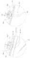
도 5는 도 3의 전자기기 다량 충전장치에 있어서 크래들에 전자기기가 삽입시 충전용 컨넥터와 충전용 포트의 접점 동작을 나타낸 도면이다.FIG. 1 is a perspective view of a massively charged electronic device according to a preferred embodiment of the present invention; FIG.
Fig. 2 is a perspective view showing a state in which the door is opened in the electronic device multi-function charging apparatus of Fig. 1; Fig.
3 is a cross-sectional view showing a state in which an electronic apparatus is stored in a cart in a state in which a door is opened in the electronic device multi-function charging apparatus of Fig. 2;
Fig. 4 is a sectional view showing a state in which a door is closed after an electronic device is stored in a cart in the electronic device mass-filling device of Fig. 3; Fig. And
Fig. 5 is a diagram showing the contact operation of the charging connector and the charging port when the electronic device is inserted into the cradle in the electronic device multi-function charging apparatus of Fig. 3;
이하, 첨부된 도면을 참조하면서 본 발명의 바람직한 실시예에 대하여 상세히 설명하기로 한다.Hereinafter, preferred embodiments of the present invention will be described in detail with reference to the accompanying drawings.
도 1은 본 발명의 바람직한 실시예에 따른 전자기기 다량 충전장치를 나타낸 사시도이고, 도 2는 도 1의 전자기기 다량 충전장치에 있어서 도어가 개방된 상태를 나타낸 사시도이며, 도 3은 도 2의 전자기기 다량 충전장치에 있어서 도어가 개방된 상태에서 카트에 전자기기가 보관되는 상태를 나타낸 단면도이고, 도 4는 도 3의 전자기기 다량 충전장치에 있어서 카트에 전자기기가 보관된 후 도어가 폐쇄되는 상태를 나타낸 단면도이다. 또한, 도 5는 도 3의 전자기기 다량 충전장치에 있어서 크래들에 전자기기가 삽입시 충전용 컨넥터와 충전용 포트의 접점 동작을 나타낸 도면이다.2 is a perspective view showing a state in which the door is opened in the electronic device multi-mass charging apparatus of FIG. 1, and FIG. 3 is a perspective view of the multi- FIG. 4 is a cross-sectional view showing a state in which the electronic device is stored in the cart in a state in which the door is opened in the electronic device mass-filling device. FIG. Fig. Fig. 5 is a diagram showing the contact operation of the charging connector and the charging port when the electronic device is inserted into the cradle in the electronic device multi-function charging apparatus of Fig. 3;
도 1 내지 도 5에 도시된 바와 같이, 본 발명의 바람직한 실시예에 따른 전자기기 다량 충전장치는, 소정의 내부 공간을 제공하는 본체(110), 본체(110)의 전면에 구성되어 본체(110)의 전면부를 개폐시키는 도어(120), 본체(110)의 내부에 위치되어 전자기기(10)가 다량으로 수납될 수 있도록 복수개의 수납공간을 제공하는 크래들(130) 및 크래들(130)의 수납공간에 대응되도록 크래들(130)에 구성되어 상기 수납공간에 전자기기(10)의 수납시 전자기기(10)의 충전용 포트(20)에 비삽입 접점되어 전원공급수단으로부터 해당 충전용 전원을 공급하는 충전용 컨넥터(140) 등을 포함한다.1 to 5, an apparatus for massively charging an electronic device according to a preferred embodiment of the present invention includes a
여기서, 상기 전자기기(10)는, 태블릿 PC 등과 같은 스마트기기로, 이는 공지의 기술이므로 상세한 설명은 생략하기로 한다.Here, the
또한, 상기 충전용 포트(20)는, 상기 전자기기(10)의 하측부 우측에 구성되어 외부의 전원공급수단으로부터 해당 동작전원이 공급 및 충전되도록 하는 인터페이스로, 비삽입식 접촉단자(21)와 자력결합부재(22)를 가지며, 이는 공지의 기술이므로 상세한 설명은 생략하기로 한다.The
상기 본체(110)는, 대략 육면체 형상으로 이루어지고 내부에 소정 공간을 가지며, 하단부에는 이동이 편리하도록 복수의 바퀴 등이 구성될 수 있다.The
여기서, 상기 본체(110)는, 하단부와 상단부에 각각 요철 구조의 결합홈과 결합블록이 구성되고 상기 결합홈과 결합블록에 각각 자성부재나 피자성부재가 구성되어 복수개의 본체가 자력을 이용하여 적층되도록 할 수 있고, 이때, 상기 바퀴의 상측도 상기 결합블록에 대응되도록 구성되어 자력을 이용하여 본체(110) 하단부의 결합홈에 간단하게 결합되는 것이 좋다.Here, the
또한, 상기 본체(110)에는, 전원공급수단과 외부의 상용전원이 연결 및 차단되도록 하는 전원버튼과 상기 충전용 컨넥터(140)와 충전용 포트(20)의 전기적 연결 상태를 표시하는 복수개의 LED가 구성되는 것이 바람직하며, 내부 공간의 온도가 설정온도 보다 높을 경우 내부 공기를 외부로 배출시키는 환기 및 냉각수단이 더 구성될 수도 있다.The
상기 도어(120)는, 본체(110)의 전면에 구성되어 본체(110)의 전면부를 상하 개폐시키는 것으로, 상기 본체(110)의 전면에 Press to Open 구조를 통하여, 도어(120)의 상단부 누름 동작시 본체(110)의 전면부 상측의 잠금 상태가 해제됨과 동시에 본체(110)의 전면부 하측의 회동수단에 연결된 도어(120)의 하단부가 소정 각도 회동되어 본체(110)의 전면부가 상하 개방되고, 반대 동작시 폐쇄되도록 한다.The
상기 크래들(130)은, 상기 본체(110)의 내부에 위치되어 전자기기(10)가 다량으로 수납될 수 있도록 복수개의 수납공간을 제공하는 수납수단으로, 충전용 포트(20)가 위치된 전자기기(10)의 하측부와 우측부를 각각 지지하는 지지판(131)과 지지벽(132)이 'L'자 형상의 단면을 가지면서 형성되는 수납체(133)와, 상기 수납체(133)의 지지판(131)에 상기 전자기기(10)의 충전용 포트(20)가 지지되도록 전자기기(10)가 세워진 상태에서 수납되도록 하는 복수개의 수납슬롯(134)을 구획하고 상기 세워진 상태로 수납된 전자기기(10)의 전면과 후면을 지지하는 슬롯벽(135) 등을 포함한다.The
여기서, 상기 수납체(133)는, 상기 본체(110)의 내부 공간에 구성되어도 좋지만, 보다 바람직하게는, 상기 도어(120)의 내측면에 지지판(131)이 위치 구성되도록 하여 상기 도어(120)의 개방시 수납슬롯(134)이 본체(110)의 전면부 개방부위를 향하도록 하여도 좋다.The
상기 슬롯벽(135)은, 전자기기(10)의 충전용 포트(20)가 위치된 하측부로부터 중간부까지에 대응되는 높이와 전자기기(10)의 두께에 대응된 이격간격으로 구성되어, 수납슬롯(134)에 전자기기(10)의 수납시 전자기기(10)가 전면 또는 후면을 향해 기울어지는 것이 방지되도록 할 수 있다.The
상기 지지벽(132)에는, 상기 수납슬롯(134)에 상기 전자기기(10)의 삽입시 전자기기(10)의 우측부에 충격이 전달되는 것을 방지하기 위한 충격방지패드(132a)가 구성되는 것이 바람직하다.The
한편, 상기 크래들(130)은, 상기 수납체(133)의 지지판(131)이 본체(110)의 바닥면 또는, 도어(120)에 구성되는 경우 도어(120)의 내측면에 대하여 소정의 각도를 가지면서 구성되는 것을 통하여, 상기 도어(120)의 개방시에는, 상기 전자기기(10)가 세워진 상태로 비스듬하게 수납슬롯(134)에 슬라이딩 삽입되면서 수납되도록 하여 간편한 수납 작업을 가능하게 할 수 있다.When the
또한, 상기 크래들(130)은, 상기와 같이 도어(120)의 내측면에 지지판(131)이 소정의 각도를 가지면서 구성되는 경우, 상기 도어(120)의 폐쇄시에는, 상기 전자기기(10)의 하측부 즉, 충전용 포트(20)가 위치된 부분과 우측부가 각각 지지판(131)과 지지벽(132)에 지지된 상태에서 소정의 기울기를 가지면서 보관되도록 하여 후술된 충전용 컨넥터(140)와 충전용 포트(20)의 접점이 상호간 이격 또는 분리되지 않고 안정적인 상태를 가지도록 할 수 있다.When the
상기 충전용 컨넥터(140)는, 상기 크래들(130)의 수납슬롯(134)에 대응되도록 구성되어 전자기기(10)의 수납시 전자기기(10)의 충전용 포트(20)에 비삽입 접점되어 전원공급수단으로부터 해당 충전용 전원을 공급하는 인터페이스수단으로, 상기 전자기기(10)가 수납슬롯(134)에 수납시 전자기기(10)의 충전용 포트(20)가 위치되는 부위에 대응되는 크래들(130) 수납체(133)의 지지판(131)에 형성된 요홈(131a)에 위치되는 하우징(141), 상기 하우징(141)의 접촉면에 구성되어 상기 전자기기(10)가 수납슬롯(134)에 수납시 전자기기(10)의 충전용 포트(20)에 구성된 접촉단자(21)에 비삽입 접점되어 전원의 공급이 가능하도록 하는 접촉단자(142) 및 상기 하우징(141)의 접촉면에 구성되어 상기 전자기기(10)가 수납슬롯(134)에 수납시 전자기기(10)의 충전용 포트(20)에 구성된 자력결합부재(22)에 자력 결합되어 상기 접촉단자(142,21) 상호간 안정적인 접점 상태를 유지하도록 하는 자력결합부재(143) 등을 포함한다.The
상기 하우징(141)은, 상기 지지판(131)의 요홈(131a) 내부에 위치된 상태에서 전자기기(10)가 수납슬롯(134)에 수납될 때 충전용 포트(20)의 자력결합부재(22)에 상기 자력결합부재(143)가 자력 결합되는 경우에는 요홈(131a)의 개구부를 향해 상승 동작되고, 그렇지 않은 경우에는 요홈(131a)의 개구부 하부로 하강 동작되어, 즉, 자력결합 여부에 따라 요홈(131a)의 상측 개구부를 향해 출입 동작되도록 구성된다.When the
즉, 상기 하우징(141)은, 상기 수납슬롯(134)에 수납 또는 수납 해제를 위해 슬라이딩되는 전자기기(10)의 하측부에 장애물이 되지 않도록 구성되어, 상기 전자기기(10)의 수납시 충전용 포트(20)와 충전용 컨넥터(140)의 자력을 이용한 비삽입 접점을 가능하게 하고, 상기 전자기기(10)의 수납 해제시 충전용 포트(20)와 충전용 컨넥터(140)의 자력결합 해제를 가능하게 할 수 있다.That is, the
여기서, 상기 하우징(141)은, 전면케이스와 후면케이스가 상호간 결합하여 육면체의 형상을 가지며, 상기 전면케이스는, 상기 전자기기(10)의 충전용 포트(20)에 접촉되는 접촉면의 상하측면이 소정길이와 곡률로 연장 형성되는 곡률부를 통하여, 충전이나 데이터 통신을 위해 충전용 포트(20)에 접촉시 충전용 포트(20)의 접촉면을 감싸도록 하여 소정 크기의 외력이 발생되더라도 상호간 안정적인 접속 상태를 유지하도록 할 수 있다.Here, the
한편, 상기 하우징(141)의 내부에는 장착부재인 장착블록이 구성되는데, 상기 장착블록에는 접촉단자(142)와 자력결합부재(143)가 해당 위치에 수용 및 구성되어 하우징(141)이 소형의 크기를 가지더라도 상기 접촉단자(142)와 자력결합부재(143)가 용이하게 구성 및 조립되도록 할 수 있다.The
상기 접촉단자(142)는, 상기 장착블록의 일측면 내측에 구비된 상태에서 PCB에 접속 실장되고 하우징(141)의 전면케이스 외부로 단부가 노출된 상태를 가진다.The
여기서, 상기 접촉단자(142)는, 상기 전자기기(10)의 충전용 포트(20)에 구성된 접촉단자(21)에 대응되는 개수로 배치될 수 있고 또한, 그 단부가 평면 또는 요홈을 가지는 평면단자와 그 단부가 내부에 구비된 스프링에 의해 탄력을 가지면서 PCB측으로 반동 삽입되거나 또는 단부만이 탄력을 가지면서 PCB측으로 휘어지는 탄력단자로 구성될 수 있다. 이때, 상기 평면단자는 접촉면에 형성되는 통공의 내부에 단자가 함몰된 구조 또는 통공의 평면에 대응되는 구조로 구성되고, 상기 탄력단자는 접촉면에 형성되는 통공의 외측으로 단자가 일부 돌출된 구조로 구성된다.The
즉, 접촉단자(142)는, 상기 충전용 포트(20)의 접촉단자(21)가 평면단자인 경우에는 탄력단자로 구성되는 것이 바람직하고, 충전용 포트(20)의 접촉단자(21)가 탄력단자인 경우에는 평면단자로 구성되는 것이 바람직하다.That is, the
또한, 상기 접촉단자(142)가 실장되는 PCB에는, 전원공급수단으로부터 해당 충전용 전원이 공급되는 것이 바람직하다.In addition, it is preferable that the charging power source is supplied from the power supply means to the PCB on which the
상기 자력결합부재(143)는, 상기 접촉단자(142)가 구성된 장착블록에 충전용 포트(20)의 자력결합부재(22)에 대응되도록 위치되는데, 자성부재로 구성되는 경우에는 자석 또는 전자석, 영구자석, 단극 또는 다극착자 중 적어도 어느 하나인 것이 바람직하고, 피자성부재인 경우에는 상기 자성부재에 자력 결합이 가능한 금속이나 강자성체를 포함하는 것이 바람직하다.The magnetic
즉, 상기 자력결합부재(143)는, 상기 충전용 포트(20)의 자력결합부재(22)가 자성부재인 경우에는 자성부재이거나 피자성부재인 것이 바람직하고, 충전용 포트(20) 자력결합부재(22)가 피자성부재인 경우에는 자성부재인 것이 바람직하다.The magnetic
여기서, 상기 자력결합부재(143)가 자석인 경우에는 자석을 물리적으로 나누지 않고 착자요크라는 설비를 통해 상하단극, 2극 및 4극착자로 제조하여 다양한 개수의 극성을 가지도록 할 수 있고, 또한, 백플레이트가 해당 자석의 배면부 또는 좌우측부 또는 상하측부 중 적어도 어느 한 곳에 위치되어 자력의 직진성 확보를 통한 자력 향상을 가능하게 할 수도 있으며, 자석들간의 자력 결합시 해당 극성끼리만 결합되도록 하여 역방향 접점을 방지하는 구조로 배치되는 경우 상기 충전용 포트(20)와 충전용 컨넥터(140)가 방향성을 가지면서 접점될 수 있다.Here, when the magnetic
한편, 상기 충전용 컨넥터(140)는, 상기 PCB에 쇼트방지부가 더 구성되는데, 상기 쇼트방지부는, 상기 비삽입 방식의 접촉단자(142)가 외부의 도체성 물질에 의해 단락되어 V-BUS와 GND의 전원공급라인에 쇼트 발생시 전자기기(10)의 충전용 포트(20))에 제공되는 전류를 차단하는 전압쇼트방지회로를 포함하는 것이 바람직하다.In addition, the charging
한편, 상기 충전용 컨넥터(140)의 하우징(141) 접촉면과 충전용 포트(20)의 접촉면에는, 상기 자력결합부재들의 자력 결합에 따른 접촉단자들의 비삽입 접점이 정확하게 이루어지도록 하는 가이드수단(미도시)이 각각 더 구성될 수 있고, 이를 통하여, 역방향 삽입도 방지할 수 있다.The contact surfaces of the
여기서, 상기 가이드수단은, 접촉면의 테두리를 감싸면서 돌출 형성되는 양각가이드와 함몰 형성되는 음각가이드 중 어느 하나로 형성될 수도 있다.Here, the guide means may be formed of any one of a relief guide formed to protrude and surround the rim of the contact surface, and an intaglio guide formed to be recessed.
즉, 충전용 포트(20)의 가이드수단이 음각가이드인 경우에는 충전용 컨넥터(140)의 가이드수단이 양각가이드로 구성되는 것이 바람직하고, 충전용 포트(20)의 가이드수단이 양각가이드인 경우 충전용 컨넥터(140)의 가이드수단이 음각가이드로 구성되는 것이 바람직하다.That is, when the guiding means of the charging
따라서 상기 충전용 컨넥터(140)에 의하면, 상기 전자기기(10)가 수납슬롯(134)에 슬라이딩 수납되어 전자기기(10)의 충전용 포트(20)가 수납슬롯(134)에 구성된 요홈(131a)에 위치되는 경우, 충전용 포트(20)의 자력결합부재(22)에 하우징(141)에 구성된 자력결합부재(142)가 자력 결합되면서 하우징(141)이 요홈(131a)의 상측 개구부를 향해 상승 동작되고 이때, 하우징(141)에 구성된 접촉단자(142)가 충전용 포트(20)의 접촉단자(21)에 비삽입 접점되어 동작 전원 또는 충전 전원이 공급되도록 할 수 있다.The
여기서, 상기 충전용 컨넥터(140)는, 상기 전자기기(10)가 수납슬롯(134)으로부터 강제 수납해제되는 경우 상기 자력결합부재들의 자력 결합이 강제 해제되고, 이때, 하우징(141)은 요홈(131a)의 내부공간으로 하강 이동된 상태를 가지게 된다.Here, the charging
이하, 본 발명의 바람직한 실시예에 따른 전자기기 다량 충전장치를 이용한 전자기기의 보관 및 충전에 대해 설명하기로 한다.Hereinafter, the storage and charging of the electronic device using the electronic device recharging apparatus according to the preferred embodiment of the present invention will be described.
먼저, 본체(110)에 Press to Open 구조를 가지면서 구성된 도어(120)의 상측부 가압시, 본체(110)의 전면부로부터 소정 각도를 가지면서 상하 방향으로 회동되는 도어(120)의 동작에 따라 본체(110)가 개방된다.The operation of the
이때, 상기 도어(120)의 내측면에는 크래들(130)이 구성되어 있고, 상기 크래들(130)은, 복수개의 전자기기(10)가 각각 수납될 수 있는 수납슬롯(134)이 구성된 지지판(131)과 지지벽(132)을 가지는 수납체(133)를 포함한다.A
이후, 작업자 또는 관리자에 의해 해당 전자기기(10)가 세워진 상태로, 즉, 전자기기(10)의 충전용 포트(20)가 위치된 하측부가 상기 수납체(133)의 지지판(131)에 위치되고 전자기기(10)의 우측부가 상기 수납체(133)의 지지벽(132)에 위치될 수 있는 상태에서 상기 수납슬롯(134)에 슬라이딩 수납된다.The lower portion of the
여기서, 상기 크래들(130)은, 상기 지지판(131)이 본체(110)의 바닥면 또는 도어(120)에 구성되는 경우 도어(120)의 내측면에 대하여 소정의 각도를 가지면서 구성되어, 상기 도어(120)의 개방시에는, 상기 전자기기(10)가 세워진 상태로 비스듬하게 수납슬롯(134)에 슬라이딩 삽입되면서 수납되도록 하여 간편한 수납 작업을 가능하게 할 수 있다.Here, the
이후, 상기와 같이, 수납슬롯(134)에 전자기기(10)가 슬라이딩 수납이 완료되면, 상기 전자기기(10)의 충전용 포트(20)가 지지판(131)의 요홈(131a) 부위에 위치하게 된다.When the
이때, 상기 지지판(131)의 요홈(131a)에는 충전용 컨넥터(140)가 위치된 상태를 가지고, 상기 충전용 컨넥터(140)는, 요홈(131a)의 내부 공간에 출입 가능하게 구성되고 상기 전자기기(10)의 충전용 포트(20)에 접촉되는 접촉면에 접촉단자(142)와 자력결합부재(143)가 구성된 하우징(141)을 포함한다.At this time, the charging
이에, 상기 하우징(141)에 구성된 자력결합부재(142)가 충전용 포트(20)의 자력결합부재(22)에 자력 결합되면서 하우징(141)이 요홈(131a)의 상측 개구부를 향해 상승 동작되고 이때, 하우징(141)에 구성된 접촉단자(142)가 충전용 포트(20)의 접촉단자(21)에 비삽입 접점되어 동작 전원 또는 충전 전원이 공급되는 상태를 가지게 된다.The magnetic
이후, 상기 도어(120)가 상하 방향으로 회동되는 동작에 따라 본체(110)가 폐쇄된 후, 본체(110)에 구성된 전원버튼의 신호 인가시 상기 하우징(141)에 전선 등을 통해 연결된 전원공급수단으로부터 충전 및 동작 전원이 공급됨에 따라 상기 전자기기(10)의 충전이 이루어지게 된다. 이때, 상기 해당 하우징(141)의 충전 동작에 대응된 신호는 본체(110)의 LED를 통해 표시되어 작업자 또는 관리자로 하여금 해당 충전용 컨넥터(140)와 전자기기(10)에 구성된 충전용 포트(20)의 전기적 연결 상태를 확인하도록 할 수 있다.Thereafter, the
따라서 상술한 바와 같은 본 발명에 의하면, 전자기기(10)가 충전장치의 크래들(130)에 보관시 전자기기(10)의 충전용 포트(20)가 크래들(130)에 구성된 충전용 컨넥터(140)에 비삽입 접점되도록 하여, 전자기기(10)의 간편한 보관 및 충전을 가능하게 할 수 있다.Therefore, when the
상술한 본 발명에서는 구체적인 실시예에 관해 설명하였으나, 여러 가지 변형이 본 발명의 범위에서 벗어나지 않고 실시될 수 있다. 따라서 발명의 범위는 설명된 실시예에 의하여 정할 것이 아니고 청구 범위와 청구 범위의 균등한 것에 의해 정해져야 한다.Although the present invention has been described with reference to the specific embodiments, various modifications may be made without departing from the scope of the present invention. Accordingly, the scope of the invention is not to be determined by the embodiments described, but should be determined by equivalents of the claims and the claims.
Claims (11)
Translated fromKorean본체(110)의 전면에 구성되어 본체(110)의 전면부를 개폐시키는 도어(120);
본체(110)의 내부에 위치되어 전자기기(10)가 다량으로 수납될 수 있도록 복수개의 수납공간을 제공하는 크래들(130); 및
크래들(130)의 수납공간에 대응되도록 크래들(130)에 구성되어 상기 수납공간에 전자기기(10)의 수납시 전자기기(10)의 충전용 포트(20)에 비삽입 접점되어 전원공급수단으로부터 해당 충전용 전원을 공급하는 충전용 컨넥터(140)를 포함하는 것을 특징으로 하는 전자기기 다량 충전장치.A main body 110 providing a predetermined internal space;
A door 120 formed on a front surface of the main body 110 to open / close a front portion of the main body 110;
A cradle (130) located inside the main body (110) and providing a plurality of storage spaces so that a large amount of the electronic devices (10) can be accommodated; And
The cradle 130 corresponds to the storage space of the cradle 130 so that the storage space is not inserted into the charging port 20 of the electronic apparatus 10 when the electronic apparatus 10 is stored therein, And a charging connector (140) for supplying the corresponding charging power source.
비삽입식 접촉단자(21)와 자력결합부재(22)를 가지는 것을 특징으로 하는 전자기기 다량 충전장치.The charging device according to claim 1, wherein the charging port (20)
And a non-insertion type contact terminal (21) and a magnetic force coupling member (22).
하단부와 상단부에 각각 요철 구조의 결합홈과 결합블록이 구성되고 상기 결합홈과 결합블록에 각각 자성부재나 피자성부재가 구성되어 복수개의 본체가 자력을 이용하여 적층되며,
상기 하단부에 이동이 편리하도록 복수의 바퀴 구성시 바퀴의 상측도 상기 결합블록에 대응되도록 구성되어 자력을 이용하여 결합홈에 결합되는 것을 특징으로 하는 전자기기 다량 충전장치.2. The apparatus of claim 1, wherein the main body (110)
Wherein a coupling groove and a coupling block are formed in a lower end portion and an upper end portion, respectively, and a magnetic member or a pneumatic member is formed in the coupling groove and the coupling block, respectively,
Wherein the upper side of the wheel is also coupled to the coupling block by a magnetic force so as to correspond to the coupling block when a plurality of wheels are configured to move at the lower end.
충전용 포트(20)가 위치된 전자기기(10)의 하측부와 우측부를 각각 지지하는 지지판(131)과 지지벽(132)이 형성되는 수납체(133)와;
상기 수납체(133)의 지지판(131)에 상기 전자기기(10)의 충전용 포트(20)가 지지되도록 전자기기(10)가 세워진 상태에서 수납되도록 하는 복수개의 수납슬롯(134)을 구획하고 수납된 전자기기(10)의 전면과 후면을 지지하는 슬롯벽(135)을 포함하는 것을 특징으로 하는 전자기기 다량 충전장치.The cradle of claim 2, wherein the cradle (130)
A housing body 133 in which a support plate 131 and a support wall 132 are formed to support the lower portion and the right portion of the electronic device 10 in which the charging port 20 is located;
A plurality of receiving slots 134 for accommodating the electronic apparatus 10 in a standing state so that the charging port 20 of the electronic apparatus 10 is supported on the support plate 131 of the housing body 133 And a slot wall (135) for supporting a front surface and a rear surface of the electronic device (10) housed therein.
상기 도어(120)의 내측면에 지지판(131)이 위치 구성되도록 하여 상기 도어(120)의 개방시 수납슬롯(134)이 본체(110)의 전면부 개방부위를 향하는 것을 특징으로 하는 전자기기 다량 충전장치.5. The apparatus according to claim 4, wherein the accommodating body (133)
Wherein a supporting plate 131 is positioned on an inner surface of the door 120 so that the receiving slot 134 of the door 120 faces the front opening portion of the main body 110 when the door 120 is opened. Charging device.
상기 수납체(133)의 지지판(131)이 본체(110)의 바닥면에 대하여 소정의 각도를 가지면서 비스듬하게 구성되는 것을 특징으로 하는 전자기기 다량 충전장치.5. The apparatus according to claim 4, wherein the accommodating body (133)
Wherein the support plate (131) of the housing (133) is configured obliquely at a predetermined angle with respect to the bottom surface of the main body (110).
상기 전자기기(10)가 수납슬롯(134)에 수납시 전자기기(10)의 충전용 포트(20)가 위치되는 부위에 대응되는 크래들(130)의 지지판(131)에 형성된 요홈(131a)에 위치되는 하우징(141);
상기 하우징(141)의 접촉면에 구성되어 상기 전자기기(10)가 수납슬롯(134)에 수납시 충전용 포트(20)에 구성된 접촉단자(21)에 비삽입 접점되는 접촉단자(142); 및
상기 하우징(141)의 접촉면에 구성되어 상기 전자기기(10)가 수납슬롯(134)에 수납시 충전용 포트(20)에 구성된 자력결합부재(22)에 자력 결합되는 자력결합부재(143)를 포함하는 것을 특징으로 하는 전자기기 다량 충전장치.5. The connector according to claim 4, wherein the charging connector (140)
The electronic apparatus 10 is inserted into the groove 131a formed in the support plate 131 of the cradle 130 corresponding to the portion where the charging port 20 of the electronic apparatus 10 is positioned when the electronic apparatus 10 is stored in the accommodation slot 134 A housing 141 to be positioned;
A contact terminal 142 formed on the contact surface of the housing 141 and non-inserted into the contact terminal 21 formed in the charging port 20 when the electronic device 10 is housed in the receiving slot 134; And
A magnetic force coupling member 143 which is formed on the contact surface of the housing 141 and is magnetically coupled to the magnetic force coupling member 22 formed on the charging port 20 when the electronic device 10 is housed in the accommodation slot 134 Wherein the electronic device is a multi-function device.
상기 지지판(131)의 요홈(131a) 내부에 위치된 상태에서 상기 자력결합부재(143)와 충전용 포트(20)의 자력결합부재(22)의 자력 결합 여부에 따라 상기 요홈(131a)의 개구부를 출입되도록 구성된 것을 특징으로 하는 전자기기 다량 충전장치.8. The apparatus according to claim 7, wherein the housing (141)
The magnetic force coupling member 22 of the magnetic force coupling member 143 and the charging port 20 is magnetically coupled with the opening of the groove 131a in a state of being positioned inside the groove 131a of the support plate 131, And the electronic device is charged and discharged.
상기 전자기기(10)의 충전용 포트(20)에 접촉되는 접촉면의 상하측면이 소정길이와 곡률로 연장 형성되는 곡률부를 가지는 것을 특징으로 하는 전자기기 다량 충전장치.8. The apparatus according to claim 7, wherein the housing (141)
Wherein the upper and lower side surfaces of the contact surface contacting the charging port (20) of the electronic device (10) have a curvature portion extended with a predetermined length and a curvature.
상기 하우징(141)의 접촉면 외부로 단부가 노출되는 탄력단자인 것을 특징으로 하는 전자기기 다량 충전장치.8. The connector according to claim 7, wherein the contact terminal (142)
And the elastic terminal is exposed at the end of the contact surface of the housing (141).
상기 하우징(141)의 접촉면에 구성되는 자성부재인 것을 특징으로 하는 전자기기 다량 충전장치.The magnetic force coupling member according to claim 7,
And a magnetic member formed on a contact surface of the housing (141).
Priority Applications (4)
| Application Number | Priority Date | Filing Date | Title |
|---|---|---|---|
| KR20140005005AKR101498537B1 (en) | 2014-01-15 | 2014-01-15 | Multi-charging apparatus for electronic equipment |
| PCT/KR2014/001792WO2015108228A1 (en) | 2014-01-15 | 2014-03-05 | Multiple electronic device charging apparatus |
| US14/302,673US20150200555A1 (en) | 2014-01-15 | 2014-06-12 | Apparatus for charging a large number of electronic devices |
| JP2014146660AJP2015133888A (en) | 2014-01-15 | 2014-07-17 | Large quantity electronic equipment charging device |
Applications Claiming Priority (1)
| Application Number | Priority Date | Filing Date | Title |
|---|---|---|---|
| KR20140005005AKR101498537B1 (en) | 2014-01-15 | 2014-01-15 | Multi-charging apparatus for electronic equipment |
Publications (1)
| Publication Number | Publication Date |
|---|---|
| KR101498537B1true KR101498537B1 (en) | 2015-03-04 |
Family
ID=53026201
Family Applications (1)
| Application Number | Title | Priority Date | Filing Date |
|---|---|---|---|
| KR20140005005AExpired - Fee RelatedKR101498537B1 (en) | 2014-01-15 | 2014-01-15 | Multi-charging apparatus for electronic equipment |
Country Status (4)
| Country | Link |
|---|---|
| US (1) | US20150200555A1 (en) |
| JP (1) | JP2015133888A (en) |
| KR (1) | KR101498537B1 (en) |
| WO (1) | WO2015108228A1 (en) |
Cited By (4)
| Publication number | Priority date | Publication date | Assignee | Title |
|---|---|---|---|---|
| WO2017008786A1 (en)* | 2015-07-15 | 2017-01-19 | Dittrich Klemens | Charging station for telecommunications devices and electronic clocks |
| KR200486212Y1 (en)* | 2017-01-25 | 2018-04-17 | (주)스마트엑세스 | Laptop charging station |
| KR102110930B1 (en)* | 2019-12-13 | 2020-05-14 | 서철승 | Electronic Device Charging Equipment |
| KR102331230B1 (en)* | 2020-06-01 | 2021-11-29 | 주식회사 서우시스템 | Mobile Terminal Cabinet |
Families Citing this family (6)
| Publication number | Priority date | Publication date | Assignee | Title |
|---|---|---|---|---|
| US20170279294A1 (en)* | 2014-09-19 | 2017-09-28 | Nec Corporation | Charging device, charging system, and electronic apparatus |
| US20160218535A1 (en)* | 2015-01-27 | 2016-07-28 | Andrew F. Prete | Rapid charging device including a plurality of charging stations |
| WO2020051804A1 (en)* | 2018-09-12 | 2020-03-19 | 森沛科技(深圳)有限公司 | Charging cabinet |
| KR102717844B1 (en) | 2019-04-11 | 2024-10-15 | 삼성전자 주식회사 | Wireless charging device for wirelessly charging a plurality of electronic device and electronic device wirelessly charging using thereof |
| US11385681B1 (en) | 2020-08-05 | 2022-07-12 | Bretford Manufacturing, Inc. | Docking computer storage system |
| JP7715552B2 (en)* | 2021-07-02 | 2025-07-30 | 株式会社オカムラ | Equipment charging trays and fixtures |
Citations (4)
| Publication number | Priority date | Publication date | Assignee | Title |
|---|---|---|---|---|
| KR20060085100A (en)* | 2005-01-22 | 2006-07-26 | (주)대한특수금속 | Non-insertable contact connector using magnet and charger for mobile terminal and mobile phone to which connector is connected |
| KR200428887Y1 (en)* | 2006-08-03 | 2006-10-16 | 김준영 | Portable Mass Filling Device |
| KR20120006636A (en)* | 2010-07-13 | 2012-01-19 | (주)열린기술 | Secondary battery charging device capable of charging a plurality of secondary batteries |
| KR200464110Y1 (en)* | 2012-10-19 | 2012-12-11 | 유현 | Charging storage device for mobile device |
Family Cites Families (18)
| Publication number | Priority date | Publication date | Assignee | Title |
|---|---|---|---|---|
| US6218796B1 (en)* | 1998-10-06 | 2001-04-17 | Mobile Design Corporation | Storage cart for rechargeable devices |
| US6008621A (en)* | 1998-10-15 | 1999-12-28 | Electronic Classroom Furniture Systems | Portable computer charging system and storage cart |
| JP2003110669A (en)* | 2001-09-28 | 2003-04-11 | Toshiba Digital Media Engineering Corp | Mobile information terminal management system and management method for the same |
| JP2003142163A (en)* | 2001-11-06 | 2003-05-16 | Copcom Co Ltd | Charging device for portable apparatus |
| US7055833B2 (en)* | 2002-01-29 | 2006-06-06 | Bretford Manufacturing, Inc. | Computer storage cart |
| USD547920S1 (en)* | 2006-04-03 | 2007-07-31 | Bretford Manufacturing, Inc. | Computer cart |
| US7844770B2 (en)* | 2006-11-02 | 2010-11-30 | Bretford Manufacturing, Inc. | Hub structure for enabling communication with a large number of handheld electronic devices |
| WO2010083459A2 (en)* | 2009-01-19 | 2010-07-22 | Bretford Manufacturing Inc | Computer cart |
| US8072183B2 (en)* | 2009-03-12 | 2011-12-06 | Griffin Technology, Inc. | Multiple interface device charger with removable battery pack |
| US8503182B2 (en)* | 2010-03-11 | 2013-08-06 | Bretford Manufacturing, Inc. | Electronic device storage tray |
| US8752848B2 (en)* | 2010-06-17 | 2014-06-17 | Bretford Manufacturing, Inc. | Computer cart |
| JP5702859B2 (en)* | 2010-06-30 | 2015-04-15 | エルゴトロン,インコーポレイティド | Electric load management system and method |
| JP5451554B2 (en)* | 2010-08-19 | 2014-03-26 | Necインフロンティア株式会社 | Portable terminal and portable terminal device |
| US8320110B2 (en)* | 2010-10-08 | 2012-11-27 | Chen-Source Inc. | Notebook computer storage and charging cart |
| KR101231874B1 (en)* | 2011-06-13 | 2013-02-08 | 주식회사 칼라세븐 | Charger for color light therapy patch |
| EP2748690A4 (en)* | 2011-08-25 | 2015-08-05 | Iomounts Llc | Apparatus and methods for supporting an article |
| US9130385B2 (en)* | 2012-01-11 | 2015-09-08 | Chen-Source Inc. | Tablet storage and charging cart |
| US8657312B2 (en)* | 2012-02-06 | 2014-02-25 | Bretford Manufacturing, Inc. | Computer cart |
- 2014
- 2014-01-15KRKR20140005005Apatent/KR101498537B1/ennot_activeExpired - Fee Related
- 2014-03-05WOPCT/KR2014/001792patent/WO2015108228A1/enactiveApplication Filing
- 2014-06-12USUS14/302,673patent/US20150200555A1/ennot_activeAbandoned
- 2014-07-17JPJP2014146660Apatent/JP2015133888A/enactivePending
Patent Citations (4)
| Publication number | Priority date | Publication date | Assignee | Title |
|---|---|---|---|---|
| KR20060085100A (en)* | 2005-01-22 | 2006-07-26 | (주)대한특수금속 | Non-insertable contact connector using magnet and charger for mobile terminal and mobile phone to which connector is connected |
| KR200428887Y1 (en)* | 2006-08-03 | 2006-10-16 | 김준영 | Portable Mass Filling Device |
| KR20120006636A (en)* | 2010-07-13 | 2012-01-19 | (주)열린기술 | Secondary battery charging device capable of charging a plurality of secondary batteries |
| KR200464110Y1 (en)* | 2012-10-19 | 2012-12-11 | 유현 | Charging storage device for mobile device |
Cited By (5)
| Publication number | Priority date | Publication date | Assignee | Title |
|---|---|---|---|---|
| WO2017008786A1 (en)* | 2015-07-15 | 2017-01-19 | Dittrich Klemens | Charging station for telecommunications devices and electronic clocks |
| EP3323185A1 (en)* | 2015-07-15 | 2018-05-23 | Dittrich, Klemens | Charging station for telecommunications devices and electronic clocks |
| KR200486212Y1 (en)* | 2017-01-25 | 2018-04-17 | (주)스마트엑세스 | Laptop charging station |
| KR102110930B1 (en)* | 2019-12-13 | 2020-05-14 | 서철승 | Electronic Device Charging Equipment |
| KR102331230B1 (en)* | 2020-06-01 | 2021-11-29 | 주식회사 서우시스템 | Mobile Terminal Cabinet |
Also Published As
| Publication number | Publication date |
|---|---|
| JP2015133888A (en) | 2015-07-23 |
| WO2015108228A1 (en) | 2015-07-23 |
| US20150200555A1 (en) | 2015-07-16 |
Similar Documents
| Publication | Publication Date | Title |
|---|---|---|
| KR101498537B1 (en) | Multi-charging apparatus for electronic equipment | |
| US10401905B2 (en) | Slide dock and methods of making and using | |
| US10582287B2 (en) | Electronic device including cover having open/close structure using magnetic force | |
| EP2736127B1 (en) | An electronic device comprising a connector port and a cable connector device | |
| KR101315688B1 (en) | Case with non-insertion type interface for potable electric apparatus | |
| CN103794943B (en) | Electrical connectors, sockets and electrical connector components | |
| US10069265B2 (en) | Interface conversion adapter and electrical connection device with the interface conversion adapter | |
| US20120162925A1 (en) | Card tray ejection mechanism and electronic device using the same | |
| US20060289444A1 (en) | In-case computer charging system | |
| KR20150047780A (en) | Electronic device with electrical connector | |
| US6007363A (en) | Magnetically latchable device for electrically coupling a power source to a circuit | |
| US20130244462A1 (en) | Power socket and electrical connector assembly | |
| CN101110508A (en) | power socket | |
| KR101736782B1 (en) | Chapter multiple mobile device charging device capable of charging mobile | |
| JP2008171652A (en) | Small magnet connector | |
| KR101285253B1 (en) | Connector docking apparatus for potable electric apparatus and non-insertion type connector for peripheral apparatus connecting thereof | |
| US20110298423A1 (en) | Universal battery charger | |
| CN203181441U (en) | Protective devices for electronic devices | |
| CN210605774U (en) | Chargeable formula electron goods shelves label system | |
| JP2020013375A (en) | Electronic device | |
| GB2490716A (en) | Mobile device charge station | |
| US20190148958A1 (en) | Casing-type Charging module for mobile device | |
| CN218474059U (en) | Electronic cigarette charging device | |
| KR101370934B1 (en) | Magnetic force type interface apparatus for electronic equipment | |
| KR101602101B1 (en) | Portable charging apparatus and fashion supplies with thereof |
Legal Events
| Date | Code | Title | Description |
|---|---|---|---|
| PA0109 | Patent application | St.27 status event code:A-0-1-A10-A12-nap-PA0109 | |
| PA0201 | Request for examination | St.27 status event code:A-1-2-D10-D11-exm-PA0201 | |
| PN2301 | Change of applicant | St.27 status event code:A-3-3-R10-R13-asn-PN2301 St.27 status event code:A-3-3-R10-R11-asn-PN2301 | |
| P11-X000 | Amendment of application requested | St.27 status event code:A-2-2-P10-P11-nap-X000 | |
| P13-X000 | Application amended | St.27 status event code:A-2-2-P10-P13-nap-X000 | |
| P11-X000 | Amendment of application requested | St.27 status event code:A-2-2-P10-P11-nap-X000 | |
| P13-X000 | Application amended | St.27 status event code:A-2-2-P10-P13-nap-X000 | |
| D13-X000 | Search requested | St.27 status event code:A-1-2-D10-D13-srh-X000 | |
| D14-X000 | Search report completed | St.27 status event code:A-1-2-D10-D14-srh-X000 | |
| PE0701 | Decision of registration | St.27 status event code:A-1-2-D10-D22-exm-PE0701 | |
| GRNT | Written decision to grant | ||
| PR0701 | Registration of establishment | St.27 status event code:A-2-4-F10-F11-exm-PR0701 | |
| PR1002 | Payment of registration fee | St.27 status event code:A-2-2-U10-U11-oth-PR1002 Fee payment year number:1 | |
| PG1601 | Publication of registration | St.27 status event code:A-4-4-Q10-Q13-nap-PG1601 | |
| PC1903 | Unpaid annual fee | St.27 status event code:A-4-4-U10-U13-oth-PC1903 Not in force date:20180227 Payment event data comment text:Termination Category : DEFAULT_OF_REGISTRATION_FEE | |
| FPAY | Annual fee payment | Payment date:20181122 Year of fee payment:4 | |
| K11-X000 | Ip right revival requested | St.27 status event code:A-6-4-K10-K11-oth-X000 | |
| PC1903 | Unpaid annual fee | St.27 status event code:N-4-6-H10-H13-oth-PC1903 Ip right cessation event data comment text:Termination Category : DEFAULT_OF_REGISTRATION_FEE Not in force date:20180227 | |
| PR0401 | Registration of restoration | St.27 status event code:A-6-4-K10-K13-oth-PR0401 | |
| PR1001 | Payment of annual fee | St.27 status event code:A-4-4-U10-U11-oth-PR1001 Fee payment year number:4 | |
| R401 | Registration of restoration | ||
| PN2301 | Change of applicant | St.27 status event code:A-5-5-R10-R11-asn-PN2301 | |
| PN2301 | Change of applicant | St.27 status event code:A-5-5-R10-R14-asn-PN2301 | |
| FPAY | Annual fee payment | Payment date:20190225 Year of fee payment:5 | |
| PR1001 | Payment of annual fee | St.27 status event code:A-4-4-U10-U11-oth-PR1001 Fee payment year number:5 | |
| PR1001 | Payment of annual fee | St.27 status event code:A-4-4-U10-U11-oth-PR1001 Fee payment year number:6 | |
| PR1001 | Payment of annual fee | St.27 status event code:A-4-4-U10-U11-oth-PR1001 Fee payment year number:7 | |
| PR1001 | Payment of annual fee | St.27 status event code:A-4-4-U10-U11-oth-PR1001 Fee payment year number:8 | |
| PR1001 | Payment of annual fee | St.27 status event code:A-4-4-U10-U11-oth-PR1001 Fee payment year number:9 | |
| R18-X000 | Changes to party contact information recorded | St.27 status event code:A-5-5-R10-R18-oth-X000 | |
| PR1001 | Payment of annual fee | St.27 status event code:A-4-4-U10-U11-oth-PR1001 Fee payment year number:10 | |
| PR1001 | Payment of annual fee | St.27 status event code:A-4-4-U10-U11-oth-PR1001 Fee payment year number:11 |