KR101498531B1 - Surgical apparatus for aneurysms - Google Patents
Surgical apparatus for aneurysmsDownload PDFInfo
- Publication number
- KR101498531B1 KR101498531B1KR1020127022741AKR20127022741AKR101498531B1KR 101498531 B1KR101498531 B1KR 101498531B1KR 1020127022741 AKR1020127022741 AKR 1020127022741AKR 20127022741 AKR20127022741 AKR 20127022741AKR 101498531 B1KR101498531 B1KR 101498531B1
- Authority
- KR
- South Korea
- Prior art keywords
- stent
- wire
- aneurysm
- microcatheter
- grid structure
- Prior art date
- Legal status (The legal status is an assumption and is not a legal conclusion. Google has not performed a legal analysis and makes no representation as to the accuracy of the status listed.)
- Active
Links
- 206010002329AneurysmDiseases0.000titleabstractdescription61
- 210000004204blood vesselAnatomy0.000claimsabstractdescription22
- 239000000463materialSubstances0.000claimsdescription27
- 238000012546transferMethods0.000claimsdescription27
- 229910052751metalInorganic materials0.000claimsdescription22
- 239000002184metalSubstances0.000claimsdescription22
- 238000000034methodMethods0.000claimsdescription22
- 230000007423decreaseEffects0.000claimsdescription8
- 229920000642polymerPolymers0.000claimsdescription8
- 239000002861polymer materialSubstances0.000claimsdescription8
- 238000009792diffusion processMethods0.000claimsdescription6
- 230000006835compressionEffects0.000claimsdescription4
- 238000007906compressionMethods0.000claimsdescription4
- 239000004810polytetrafluoroethyleneSubstances0.000claimsdescription3
- 229920001343polytetrafluoroethylenePolymers0.000claimsdescription3
- 238000009941weavingMethods0.000claims1
- 230000003902lesionEffects0.000abstractdescription18
- 210000003462veinAnatomy0.000abstractdescription4
- 230000000694effectsEffects0.000abstractdescription2
- 238000007599dischargingMethods0.000abstract1
- 210000001367arteryAnatomy0.000description5
- 230000017531blood circulationEffects0.000description5
- 238000001356surgical procedureMethods0.000description5
- 238000012800visualizationMethods0.000description5
- 230000010102embolizationEffects0.000description4
- 230000002792vascularEffects0.000description4
- 238000005452bendingMethods0.000description3
- 230000002980postoperative effectEffects0.000description3
- 231100000216vascular lesionToxicity0.000description3
- 208000002223abdominal aortic aneurysmDiseases0.000description2
- 210000003484anatomyAnatomy0.000description2
- 238000009954braidingMethods0.000description2
- 239000003086colorantSubstances0.000description2
- 238000013508migrationMethods0.000description2
- 230000005012migrationEffects0.000description2
- BASFCYQUMIYNBI-UHFFFAOYSA-NplatinumChemical compound[Pt]BASFCYQUMIYNBI-UHFFFAOYSA-N0.000description2
- 210000003556vascular endothelial cellAnatomy0.000description2
- 229910000838Al alloyInorganic materials0.000description1
- 229910000881Cu alloyInorganic materials0.000description1
- 201000008450Intracranial aneurysmDiseases0.000description1
- 229910000831SteelInorganic materials0.000description1
- 208000002847Surgical WoundDiseases0.000description1
- 208000007474aortic aneurysmDiseases0.000description1
- 238000013459approachMethods0.000description1
- 239000008280bloodSubstances0.000description1
- 210000004369bloodAnatomy0.000description1
- 210000005013brain tissueAnatomy0.000description1
- 210000001627cerebral arteryAnatomy0.000description1
- 230000002490cerebral effectEffects0.000description1
- 230000006378damageEffects0.000description1
- 201000010099diseaseDiseases0.000description1
- 208000037265diseases, disorders, signs and symptomsDiseases0.000description1
- 238000005516engineering processMethods0.000description1
- 239000004744fabricSubstances0.000description1
- 230000004927fusionEffects0.000description1
- PCHJSUWPFVWCPO-UHFFFAOYSA-NgoldChemical compound[Au]PCHJSUWPFVWCPO-UHFFFAOYSA-N0.000description1
- 229910052737goldInorganic materials0.000description1
- 239000010931goldSubstances0.000description1
- 230000035876healingEffects0.000description1
- 210000001006meconiumAnatomy0.000description1
- 229910001000nickel titaniumInorganic materials0.000description1
- 229910052697platinumInorganic materials0.000description1
- 238000005498polishingMethods0.000description1
- 102000054765polymorphisms of proteinsHuman genes0.000description1
- 230000003014reinforcing effectEffects0.000description1
- 238000011160researchMethods0.000description1
- 230000035939shockEffects0.000description1
- 239000010935stainless steelSubstances0.000description1
- 229910001220stainless steelInorganic materials0.000description1
- 239000010959steelSubstances0.000description1
- 229910052715tantalumInorganic materials0.000description1
- GUVRBAGPIYLISA-UHFFFAOYSA-Ntantalum atomChemical compound[Ta]GUVRBAGPIYLISA-UHFFFAOYSA-N0.000description1
- WFKWXMTUELFFGS-UHFFFAOYSA-NtungstenChemical compound[W]WFKWXMTUELFFGS-UHFFFAOYSA-N0.000description1
- 229910052721tungstenInorganic materials0.000description1
- 239000010937tungstenSubstances0.000description1
- 230000000007visual effectEffects0.000description1
- 238000003466weldingMethods0.000description1
- 238000004804windingMethods0.000description1
Images


Classifications
- A—HUMAN NECESSITIES
- A61—MEDICAL OR VETERINARY SCIENCE; HYGIENE
- A61B—DIAGNOSIS; SURGERY; IDENTIFICATION
- A61B17/00—Surgical instruments, devices or methods
- A61B17/12—Surgical instruments, devices or methods for ligaturing or otherwise compressing tubular parts of the body, e.g. blood vessels or umbilical cord
- A61B17/12022—Occluding by internal devices, e.g. balloons or releasable wires
- A61B17/12099—Occluding by internal devices, e.g. balloons or releasable wires characterised by the location of the occluder
- A61B17/12109—Occluding by internal devices, e.g. balloons or releasable wires characterised by the location of the occluder in a blood vessel
- A61B17/12113—Occluding by internal devices, e.g. balloons or releasable wires characterised by the location of the occluder in a blood vessel within an aneurysm
- A61B17/12118—Occluding by internal devices, e.g. balloons or releasable wires characterised by the location of the occluder in a blood vessel within an aneurysm for positioning in conjunction with a stent
- A—HUMAN NECESSITIES
- A61—MEDICAL OR VETERINARY SCIENCE; HYGIENE
- A61F—FILTERS IMPLANTABLE INTO BLOOD VESSELS; PROSTHESES; DEVICES PROVIDING PATENCY TO, OR PREVENTING COLLAPSING OF, TUBULAR STRUCTURES OF THE BODY, e.g. STENTS; ORTHOPAEDIC, NURSING OR CONTRACEPTIVE DEVICES; FOMENTATION; TREATMENT OR PROTECTION OF EYES OR EARS; BANDAGES, DRESSINGS OR ABSORBENT PADS; FIRST-AID KITS
- A61F2/00—Filters implantable into blood vessels; Prostheses, i.e. artificial substitutes or replacements for parts of the body; Appliances for connecting them with the body; Devices providing patency to, or preventing collapsing of, tubular structures of the body, e.g. stents
- A61F2/82—Devices providing patency to, or preventing collapsing of, tubular structures of the body, e.g. stents
- A61F2/86—Stents in a form characterised by the wire-like elements; Stents in the form characterised by a net-like or mesh-like structure
- A—HUMAN NECESSITIES
- A61—MEDICAL OR VETERINARY SCIENCE; HYGIENE
- A61F—FILTERS IMPLANTABLE INTO BLOOD VESSELS; PROSTHESES; DEVICES PROVIDING PATENCY TO, OR PREVENTING COLLAPSING OF, TUBULAR STRUCTURES OF THE BODY, e.g. STENTS; ORTHOPAEDIC, NURSING OR CONTRACEPTIVE DEVICES; FOMENTATION; TREATMENT OR PROTECTION OF EYES OR EARS; BANDAGES, DRESSINGS OR ABSORBENT PADS; FIRST-AID KITS
- A61F2/00—Filters implantable into blood vessels; Prostheses, i.e. artificial substitutes or replacements for parts of the body; Appliances for connecting them with the body; Devices providing patency to, or preventing collapsing of, tubular structures of the body, e.g. stents
- A61F2/02—Prostheses implantable into the body
- A61F2/04—Hollow or tubular parts of organs, e.g. bladders, tracheae, bronchi or bile ducts
- A61F2/06—Blood vessels
- A—HUMAN NECESSITIES
- A61—MEDICAL OR VETERINARY SCIENCE; HYGIENE
- A61F—FILTERS IMPLANTABLE INTO BLOOD VESSELS; PROSTHESES; DEVICES PROVIDING PATENCY TO, OR PREVENTING COLLAPSING OF, TUBULAR STRUCTURES OF THE BODY, e.g. STENTS; ORTHOPAEDIC, NURSING OR CONTRACEPTIVE DEVICES; FOMENTATION; TREATMENT OR PROTECTION OF EYES OR EARS; BANDAGES, DRESSINGS OR ABSORBENT PADS; FIRST-AID KITS
- A61F2/00—Filters implantable into blood vessels; Prostheses, i.e. artificial substitutes or replacements for parts of the body; Appliances for connecting them with the body; Devices providing patency to, or preventing collapsing of, tubular structures of the body, e.g. stents
- A61F2/82—Devices providing patency to, or preventing collapsing of, tubular structures of the body, e.g. stents
- A61F2/86—Stents in a form characterised by the wire-like elements; Stents in the form characterised by a net-like or mesh-like structure
- A61F2/90—Stents in a form characterised by the wire-like elements; Stents in the form characterised by a net-like or mesh-like structure characterised by a net-like or mesh-like structure
- A—HUMAN NECESSITIES
- A61—MEDICAL OR VETERINARY SCIENCE; HYGIENE
- A61F—FILTERS IMPLANTABLE INTO BLOOD VESSELS; PROSTHESES; DEVICES PROVIDING PATENCY TO, OR PREVENTING COLLAPSING OF, TUBULAR STRUCTURES OF THE BODY, e.g. STENTS; ORTHOPAEDIC, NURSING OR CONTRACEPTIVE DEVICES; FOMENTATION; TREATMENT OR PROTECTION OF EYES OR EARS; BANDAGES, DRESSINGS OR ABSORBENT PADS; FIRST-AID KITS
- A61F2/00—Filters implantable into blood vessels; Prostheses, i.e. artificial substitutes or replacements for parts of the body; Appliances for connecting them with the body; Devices providing patency to, or preventing collapsing of, tubular structures of the body, e.g. stents
- A61F2/95—Instruments specially adapted for placement or removal of stents or stent-grafts
- A61F2/962—Instruments specially adapted for placement or removal of stents or stent-grafts having an outer sleeve
- A61F2/966—Instruments specially adapted for placement or removal of stents or stent-grafts having an outer sleeve with relative longitudinal movement between outer sleeve and prosthesis, e.g. using a push rod
- A—HUMAN NECESSITIES
- A61—MEDICAL OR VETERINARY SCIENCE; HYGIENE
- A61L—METHODS OR APPARATUS FOR STERILISING MATERIALS OR OBJECTS IN GENERAL; DISINFECTION, STERILISATION OR DEODORISATION OF AIR; CHEMICAL ASPECTS OF BANDAGES, DRESSINGS, ABSORBENT PADS OR SURGICAL ARTICLES; MATERIALS FOR BANDAGES, DRESSINGS, ABSORBENT PADS OR SURGICAL ARTICLES
- A61L27/00—Materials for grafts or prostheses or for coating grafts or prostheses
- A61L27/02—Inorganic materials
- A61L27/04—Metals or alloys
- A—HUMAN NECESSITIES
- A61—MEDICAL OR VETERINARY SCIENCE; HYGIENE
- A61B—DIAGNOSIS; SURGERY; IDENTIFICATION
- A61B17/00—Surgical instruments, devices or methods
- A61B17/12—Surgical instruments, devices or methods for ligaturing or otherwise compressing tubular parts of the body, e.g. blood vessels or umbilical cord
- A61B17/12022—Occluding by internal devices, e.g. balloons or releasable wires
- A61B2017/1205—Introduction devices
- A—HUMAN NECESSITIES
- A61—MEDICAL OR VETERINARY SCIENCE; HYGIENE
- A61F—FILTERS IMPLANTABLE INTO BLOOD VESSELS; PROSTHESES; DEVICES PROVIDING PATENCY TO, OR PREVENTING COLLAPSING OF, TUBULAR STRUCTURES OF THE BODY, e.g. STENTS; ORTHOPAEDIC, NURSING OR CONTRACEPTIVE DEVICES; FOMENTATION; TREATMENT OR PROTECTION OF EYES OR EARS; BANDAGES, DRESSINGS OR ABSORBENT PADS; FIRST-AID KITS
- A61F2/00—Filters implantable into blood vessels; Prostheses, i.e. artificial substitutes or replacements for parts of the body; Appliances for connecting them with the body; Devices providing patency to, or preventing collapsing of, tubular structures of the body, e.g. stents
- A61F2/82—Devices providing patency to, or preventing collapsing of, tubular structures of the body, e.g. stents
- A61F2002/823—Stents, different from stent-grafts, adapted to cover an aneurysm
- A—HUMAN NECESSITIES
- A61—MEDICAL OR VETERINARY SCIENCE; HYGIENE
- A61F—FILTERS IMPLANTABLE INTO BLOOD VESSELS; PROSTHESES; DEVICES PROVIDING PATENCY TO, OR PREVENTING COLLAPSING OF, TUBULAR STRUCTURES OF THE BODY, e.g. STENTS; ORTHOPAEDIC, NURSING OR CONTRACEPTIVE DEVICES; FOMENTATION; TREATMENT OR PROTECTION OF EYES OR EARS; BANDAGES, DRESSINGS OR ABSORBENT PADS; FIRST-AID KITS
- A61F2250/00—Special features of prostheses classified in groups A61F2/00 - A61F2/26 or A61F2/82 or A61F9/00 or A61F11/00 or subgroups thereof
- A61F2250/0014—Special features of prostheses classified in groups A61F2/00 - A61F2/26 or A61F2/82 or A61F9/00 or A61F11/00 or subgroups thereof having different values of a given property or geometrical feature, e.g. mechanical property or material property, at different locations within the same prosthesis
- A61F2250/0015—Special features of prostheses classified in groups A61F2/00 - A61F2/26 or A61F2/82 or A61F9/00 or A61F11/00 or subgroups thereof having different values of a given property or geometrical feature, e.g. mechanical property or material property, at different locations within the same prosthesis differing in density or specific weight
Landscapes
- Health & Medical Sciences (AREA)
- Engineering & Computer Science (AREA)
- Biomedical Technology (AREA)
- Life Sciences & Earth Sciences (AREA)
- Veterinary Medicine (AREA)
- Public Health (AREA)
- General Health & Medical Sciences (AREA)
- Animal Behavior & Ethology (AREA)
- Heart & Thoracic Surgery (AREA)
- Vascular Medicine (AREA)
- Transplantation (AREA)
- Oral & Maxillofacial Surgery (AREA)
- Cardiology (AREA)
- Surgery (AREA)
- Reproductive Health (AREA)
- Neurosurgery (AREA)
- Molecular Biology (AREA)
- Medical Informatics (AREA)
- Chemical & Material Sciences (AREA)
- Nuclear Medicine, Radiotherapy & Molecular Imaging (AREA)
- Gastroenterology & Hepatology (AREA)
- Inorganic Chemistry (AREA)
- Pulmonology (AREA)
- Dermatology (AREA)
- Epidemiology (AREA)
- Medicinal Chemistry (AREA)
- Media Introduction/Drainage Providing Device (AREA)
- Prostheses (AREA)
- Surgical Instruments (AREA)
Abstract
Translated fromKoreanDescription
Translated fromKorean본 발명은 의료기기 분야에 관한 것으로서, 특히 동맥류 수술장치에 관한 것이다.BACKGROUND OF THE
동맥류는 동맥혈관벽(동맥벽)의 질병, 손상 혹은 선천적 요인으로 인해 혈관벽의 국부적인 취약을 초래하여 혈류의 충격하에 혈관벽의 취약점이 외부로 돌출되어 차츰 확장되면서 형성된 것이다. 동맥류는 신체의 부동한 부위에서 발생할 수 있고 가장 흔한 동맥류로는 복부 대동맥 동맥류와 대뇌 동맥류이다. 동맥류 치료의 목적은 동맥류 파열의 위험을 감소하는 것이고 가장 근본적인 치료방법은 모체 동맥류를 지닌 동맥의 유합(healing) 및 동맥벽 해부구조의 재건을 실현하는 것이다.
Aneurysms are caused by disease, damage or inherent factors of the arterial wall (arterial wall) resulting in local weakness of the vessel wall, resulting in a gradual expansion of the vascular wall of the vessel under the shock of blood flow. Aneurysms can occur in different parts of the body, and the most common aneurysms are abdominal aortic aneurysms and cerebral aneurysms. The purpose of the aneurysm treatment is to reduce the risk of rupture of the aneurysm, and the most fundamental treatment is to achieve healing of the arterial artery aneurysm and reconstruction of the arterial wall anatomy.
현재, 혈관내에 개입하여 동맥류를 치료하는데 있어서 주로 스텐트가 스프링 코일을 보조 사용하는 방법을 사용한다. 즉, 적당한 밀도의 스텐트를 병변 혈관내에 이송한 후 스프링 코일을 스텐트의 틈새를 통하여 동맥류 내에 이송하여 동맥류를 메움으로써 치료의 목적을 실현한다.Currently, a stent is used as a supplementary use of a spring coil in the treatment of an aneurysm intervening in a blood vessel. In other words, after delivering a stent with a proper density into the lesion, the spring coil is transferred into the aneurysm through the gap of the stent to fill the aneurysm and realize the purpose of the treatment.
동맥류 색전술의 최종적인 치료행위는 동맥류강 내에서 발생한다. 출원인은 기존 기술에 대한 연구를 거친 결과, 기존의 스텐트가 스프링 코일을 보조 사용하는 방식은 동맥류를 치료하는 과정 중 스프링 코일이 자리를 차지하는 현상이 존재하고 또 동맥류 주위의 뇌조직, 중요한 혈관 및 신경이 압박당하는 증상이 나타남과 동시에 스프링 코일의 색전술에 있어서 치밀율이 낮고 또 수술후 재발률이 높음을 발견하였다. 또한, 스프링 코일의 헤드부는 비교적 얇은 동맥류벽을 파손시키기 쉽기 때문에 일단 동맥류가 파열되면 환자가 수술 중 혹은 수술 후 사망하는 후과를 초래할 수 있다.The final treatment of aneurysm embolization is within the aneurysm. As a result of the research on the existing technology, the applicant has found that the spring coil is used as a supplementary use of the conventional stent, and the spring coil takes place in the process of treating the aneurysm, and the brain tissue around the aneurysm, We also found that the compression rate of the spring coil was low and the postoperative recurrence rate was high. In addition, since the head of the spring coil is prone to break the relatively thin aneurysm wall, once the aneurysm ruptures, the patient may cause post-operative or post-operative death.
상기 기술적 과제를 해결하기 위하여, 본 발명의 실시예에 따른 동맥류 수술장치의 기술방안은 하기와 같다.
In order to solve the above-mentioned technical problems, technical solutions of an aneurysm surgical apparatus according to an embodiment of the present invention are as follows.
스텐트, 이송용 와이어, 도입관(introducing sheath), 마이크로 카테터를 포함하는 동맥류 수술장치에 있어서, 상기 스텐트는 자가팽창식 스텐트이고, 상기 이송용 와이어는 상기 도입관 내강 내에 설치하고 그 외부에는 상기 스텐트가 속박되어 있으며, 상기 도입관과 상기 마이크로 카테터는 서로 연결되고 내강이 서로 통함으로써 상기 이송용 와이어와 상기 스텐트가 인체로 이송되고 진입하는 통로를 형성한다.
1. An aneurysm surgical device comprising a stent, a transferring wire, an introducing sheath, and a microcatheter, wherein the stent is a self-inflating stent, the transferring wire is installed in the introducing tube lumen, And the introduction tube and the microcatheter are connected to each other and the lumens communicate with each other to form a path through which the transferring wire and the stent are transferred to and introduced into the human body.
상기 자가팽창식 스텐트는 생체 적합성을 갖는 금속 와이어 체인 및/또는 폴리머 와이어 체인이 엮어져 형성되는 것이 바람직하다.
Preferably, the self-inflating stent is formed by twisting a metal wire chain and / or a polymer wire chain having biocompatibility.
상기 자가팽창식 스텐트의 구조는 망관상 구조(mesh tube structure)인 것이 바람직하다.
The structure of the self-inflating stent is preferably a mesh tube structure.
상기 망관상 구조의 지름방향의 압축비는 1:2~1:10 범위 내에 있는 것이 바람직하다.
It is preferable that the radial compression ratio of the network tubular structure is in the range of 1: 2 to 1:10.
상기 망관상 구조는 균일한 그리드 구조인 것이 바람직하다.
The network tubular structure is preferably a uniform grid structure.
상기 균일한 그리드 구조의 커버율은 20%~60% 범위 내에 있는 것이 바람직하다.
The coverage of the uniform grid structure is preferably in the range of 20% to 60%.
상기 균일한 그리드 구조의 커버율은 30%~50% 범위 내에 있는 것이 바람직하다.
The cover ratio of the uniform grid structure is preferably in the range of 30% to 50%.
상기 망관상 구조는 동맥류 위치의 축방향 및/또는 지름방향에서 불균일한 그리드 구조를 가지고 나머지 부위에서 균일한 그리드 구조를 가지는 것이 바람직하다.
It is preferable that the network tubular structure has a non-uniform grid structure in the axial direction and / or the radial direction of the aneurysm position and a uniform grid structure in the remaining portion.
상기 불균일한 그리드 구조의 커버율은 40%~60% 범위 내에 있는 것이 바람직하다.
It is preferable that the coverage of the non-uniform grid structure is within the range of 40% to 60%.
상기 균일한 그리드 구조의 커버율은 20%~40% 범위 내에 있는 것이 바람직하다.
The cover ratio of the uniform grid structure is preferably in the range of 20% to 40%.
상기 이송용 와이어는, 상기 스텐트를 이송하고 지지하는 금속 코어와, 상기 금속 코어 상에 커버된 스프링 소자와, 상기 금속 코어 상에 고정되고 이송시 상기 스텐트에 추진력을 부여하는 돌출대(boss)와, 상기 스프링 소자 혹은 금속 코어의 외부 표면에 고정되고 이송시 상기 스텐트에 추진력 혹은 회수력을 부여하는 복수개의 이송위치 지정 소자를 포함하는 것이 바람직하다.
The transport wire includes a metal core for transporting and supporting the stent, a spring element covered on the metal core, a boss fixed on the metal core and imparting a driving force to the stent during transportation, And a plurality of transfer position designating elements fixed to an outer surface of the spring element or the metal core and imparting an impelling force or a revolving force to the stent during transportation.
상기 스프링 소자, 돌출대 및 이송 소자의 재료는 시각화 재료(visualizable material)인 것이 바람직하다.
Preferably, the material of the spring element, protrusion and transfer element is a visualizable material.
상기 도입관의 구조는 중공구조인 것이 바람직하다.
The structure of the introduction pipe is preferably a hollow structure.
상기 도입관의 재료는 고분자 재료인 것이 바람직하다.
The material of the introduction pipe is preferably a polymer material.
상기 고분자 재료는 PTFE 재료, HDFE 재료 혹은 FEP 재료인 것이 바람직하다.
The polymer material is preferably a PTFE material, an HDFE material, or an FEP material.
상기 마이크로 카테터는 직경이 근단(proximal end)에서 원단(distal end)으로 차츰 감소되고 경도가 근단에서 원단으로 차츰 감소되는 계단상의 중공구조를 가지는 파이프체와, 일단이 상기 파이프체와 연결되어 상기 파이프체의 근단에서 절단이 발생하는 것을 방지하는 응력 확산튜브와, 상기 응력 확산튜브의 다른 일단과 연결되고 상기 도입관이 삽입되어 상기 도입관과 상기 파이프체를 연결시키는 연결부를 포함하는 것이 바람직하다.
Wherein the microcatheter comprises a tubular body having a stepwise hollow structure in which the diameter gradually decreases from the proximal end to the distal end and the hardness gradually decreases from the near end to the far end, And a connecting portion connected to the other end of the stress diffusion tube and inserted into the introduction pipe to connect the introduction pipe and the pipe body.
상기 파이프체의 재료는 안에서 밖으로 각각 스무스층, 강화층 및 케이스층이고 재료는 각각 고분자 재료, 금속 및/또는 폴리머, 고분자 재료인 것이 바람직하다.
Preferably, the material of the pipe body is a smooth layer, an enhancement layer and a case layer, respectively, and the material is polymer material, metal and / or polymer and polymer material, respectively.
상기 파이프체의 원단에는 혈관 중 상기 마이크로 카테터의 위치를 나타내는 시각화 소자가 더 설치되어 있는 것이 바람직하다.
It is preferable that a visualizing element indicating the position of the microcatheter in the blood vessel is further provided on the distal end of the pipe body.
상기 본 발명의 실시예에 따른 기술방안으로부터 알 수 있는 바와 같이, 본 발명의 실시예에 따른 동맥류 수술장치 중의 스텐트는 고밀도 그리드 구조를 가짐으로써 스텐트로 하여금 비교적 높은 커버율을 구비하도록 하고, 특히 동맥류 부근의 스텐트상의 높은 커버율, 불균일한 그리드 구조는 방출 후의 스텐트가 혈관 병변 위치에서 동맥벽을 재건하도록 함으로써 병변 위치의 혈류 방향을 현저히 개선시켜 혈액이 동맥류 내벽에 대한 충격을 해소하여 혈관 동맥류를 치료하는 목적을 실현한다. 동시에, 스텐트의 고밀도 메쉬는 혈관 내피세포의 생장 혹은 이동을 지지함으로써 동맥류 입구 부근의 내막의 생장을 가속화시키고 병변 위치의 혈관 내막화를 실현하여 진정한 동맥류의 해부치료를 실현한다.
As can be seen from the technical solution according to the embodiment of the present invention, the stent in the aneurysmal surgical apparatus according to the embodiment of the present invention has a high density grid structure so that the stent has a relatively high coverage ratio, The high coverage rate and uneven grid structure of the stent for the purpose of reconstructing the arterial wall at the location of the vessel lesion after the release of the stent significantly improves the blood flow direction of the lesion to relieve the impact on the inner wall of the aneurysm, Realization. At the same time, the high-density mesh of the stent supports the growth or migration of vascular endothelial cells, accelerating the growth of the intima around the aneurysm entrance, realizing vascular endothelialization at the lesion site, and realizing an aneurysmal treatment of the true aneurysm.
본 발명의 실시예에 따른 동맥류 수술장치에 있어서, 스텐트는 이송용 와이어상에 속박되어 있고 스텐트와 이송용 와이어를 도입관 내에 사전 장착한 후, 수술 중 이송시 우선 마이크로 카테터를 병변 혈관 위치에 삽입한 다음 도입관과 마이크로 카테터를 상호 연결하며 이송용 와이어에 축방향의 힘을 인가함으로써 이송용 와이어에 속박된 스텐트를 도입관에서 마이크로 카테터에 이송할 수 있고 또한 혈관 병변 위치까지 이동할 수 있다. 이송용 와이어와 마이크로 카테터의 상대적 위치를 조정함으로써 마지막 단계에서 스텐트의 위치를 지정하고 스텐트를 혈관의 병변 위치에 방출한다.In an aneurysm surgical apparatus according to an embodiment of the present invention, a stent is constrained on a transferring wire, and a stent and a transferring wire are pre-mounted in an introducing tube, and then a microcatheter is first inserted The stent tethered to the transfer wire can be transferred from the introducer tube to the microcatheter and can also be moved to the vascular lesion location by interconnecting the introducer tube and the microcatheter and applying an axial force to the transfer wire. By adjusting the relative position of the transfer wire and the microcatheter, the position of the stent is located at the final stage and the stent is released to the lesion site of the blood vessel.
한편, 본 발명의 실시예에 따른 동맥류 수술장치 중의 스텐트는 혈관 병변 위치까지 이송 및 방출된 후 동맥류 내의 색전 재료(예를 들어, 분리가능한 코일, 색전액 등)로서 지지하거나 차단함으로써 색전 재료가 동맥류 내에만 존재하도록 확보하고 동맥류를 지닌 동맥의 원활함을 유지하며 혈관 동맥류에 대해 보조 치료할 수 있다.Meanwhile, the stent in the aneurysmal surgical apparatus according to the embodiment of the present invention is supported and blocked as an embolization material (for example, detachable coil, colorant, etc.) in the aneurysm after being transferred to and discharged from the vessel lesion site, The aneurysm is an aneurysm of the aneurysm.
본 발명의 실시예 혹은 기존 기술에 따른 기술방안을 더욱 명확히 설명하고자, 이하 실시예 혹은 기존 기술에 관한 설명에 따른 첨부된 도면에 대해 간단하게 설명하기로 한다. 여기서 설명된 도면은 오직 본 발명에서 기재된 일부 실시예이며, 당해 기술분야의 당업자들에 있어서 창조적인 노력없이 첨부한 도면을 통하여 기타 도면을 얻을 수 있음은 자명한 것이다.
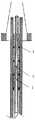
도 1은 본 발명의 실시예에 따른 동맥류 수술장치 구조 사시도이다.
도 2는 본 발명의 실시예에 따른 동맥류 수술장치의 국부적인 단면도이다.
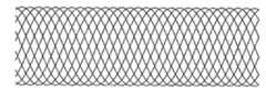
도 3은 본 발명의 실시예에 따른 스텐트의 구조 사시도이다.
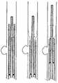
도 4a 및 4b는 본 발명의 실시예에 따른 스텐트의 압축 사시도이다.
도 5a 및 5b는 본 발명의 실시예에 따른 스텐트의 망관상 구조에 대한 평면 사시도이다.
도 6은 본 발명의 실시예에 따른 이송용 와이어의 구조 사시도이다.
도 7a 및 7b는 본 발명의 실시예에 따른 이송용 와이어의 돌출대 및 이송 소자의 구조 사시도이다.
도 8은 본 발명의 실시예에 따른 마이크로 카테터의 구조 사시도이다.
도 9는 본 발명의 실시예에 따른 스텐트가 혈관 병변 위치로 이송되는 것을 나타내는 사시도이다.
도 10은 본 발명의 실시예에 따른 "밀면서 회수하는 방식(pushing-and-withdrawing way)"을 이용하여 스텐트를 방출하는 것을 나타내는 사시도이다.
도 11은 본 발명의 실시예에 따른 "회수하면서 미는 방식(withdrawing-and-pushing way)"을 이용하여 스텐트를 방출하는 것을 나타내는 사시도이다.BRIEF DESCRIPTION OF THE DRAWINGS The accompanying drawings, which are included to provide a further understanding of the invention and are incorporated in and constitute a part of this specification, illustrate embodiments of the invention and, together with the description, serve to explain the principles of the invention. It is to be understood that the drawings described herein are only illustrative of some embodiments of the invention and that other drawings may be obtained through the accompanying drawings without undue effort by those skilled in the art.
1 is a structural perspective view of an aneurysmal surgical apparatus according to an embodiment of the present invention.
2 is a partial cross-sectional view of an aneurysm surgical apparatus according to an embodiment of the present invention.
3 is a structural perspective view of a stent according to an embodiment of the present invention.
4A and 4B are exploded perspective views of a stent according to an embodiment of the present invention.
5A and 5B are plan and perspective views of a network tubular structure of a stent according to an embodiment of the present invention.
6 is a structural perspective view of a transfer wire according to an embodiment of the present invention.
7A and 7B are structural perspective views of a protrusion of a transfer wire and a transfer device according to an embodiment of the present invention.
8 is a structural perspective view of a microcatheter according to an embodiment of the present invention.
9 is a perspective view illustrating the delivery of a stent according to an embodiment of the present invention to a vein lesion location.
Fig. 10 is a perspective view showing the stent being released using a "pushing-and-withdrawing way" according to an embodiment of the present invention.
Figure 11 is a perspective view illustrating stent release using a "withdrawing-and-pushing way" according to an embodiment of the present invention.
동맥류의 가장 근본적인 치료방법은 모체 동맥류를 지닌 동맥의 유합 및 동맥벽 해부구조의 재건을 실현하는 것이다. 하지만 기존의 외과 스텐트가 스프링 코일을 보조 사용하여 혈관에 개입시키는 치료방법에 의하면, 동맥류 치료과정 중 스프링 코일이 자리를 차지하는 현상과 색전의 불치밀 그리고 수술 중 혹은 수술 후 동맥류 파열의 위험이 존재한다.
The most fundamental treatment for aneurysms is to achieve fusion of the arteries with meconium aneurysms and reconstruction of the arterial wall anatomy. However, according to the treatment method in which the conventional surgical stent intervenes in the blood vessel by using the spring coil as an auxiliary, there is a risk that the spring coil takes place during the aneurysm treatment, inconspicuous embolization, and rupture of the aneurysm during operation or operation .
본 발명의 실시예에 따른 동맥류 수술장치에 의하면, 고밀도의 초유연한 스텐트를 혈관 병변 위치까지 이송하고 방출할 수 있고 스텐트의 혈관 병변 위치에서의 그리드 구조는 비교적 높은 커버율을 가짐으로써 상기 방출되어 혈관 속에 진입한 스텐트가 동맥류를 지닌 혈관의 유합과 동일한 효과를 얻어 혈관 동맥류가 더욱 잘 치료될 수 있도록 한다.
According to an aneurysm surgical apparatus according to an embodiment of the present invention, a high-density super-flexible stent can be transferred to and discharged from a vascular lesion site, and a grid structure at a position of the vascular lesion of the stent has a relatively high coverage rate, An aneurysm of the aneurysm can be treated more effectively by the entering stent with the same effect as the union of the aneurysm.
상기 내용은 본 발명의 핵심적인 사상이고 당해 기술분야의 당업자들이 본 발명의 기술방안을 더욱 잘 이해하도록 아래 본 발명의 실시예에 따른 도면을 참조하여 본 발명의 실시예에 따른 기술방안에 대하여 상세한 설명을 하도록 한다. 하기 설명하는 실시예는 단지 본 발명의 일부 실시예이며, 모든 실시예는 아니다. 본 발명의 실시예에 기초하여 당해 기술분야의 당업자들이 창조적인 노력없이 얻은 기타 모든 실시예도 본 발명이 보호하는 범위에 속하는 것으로 해석되어야 한다.
The above description is a key idea of the present invention and it will be understood by those of ordinary skill in the art in view of the following detailed description of the preferred embodiments of the present invention with reference to the accompanying drawings, Explain it. The embodiments described below are merely some embodiments of the invention and not all embodiments. All other embodiments obtained by those skilled in the art without the creative effort based on the embodiments of the present invention should be construed as being within the scope of protection of the present invention.
본 발명의 실시예는 동맥류 수술장치에 관한 것이다.
An embodiment of the present invention relates to an aneurysmal surgical apparatus.
도 1은 당해 동맥류 수술장치의 외부 구조 사시도이고, 도 2는 당해 수술 혈관 장치의 국부적인 단면도이다. 도 1과 도 2를 결합하면, 당해 동맥류 수술장치는 스텐트(1), 이송용 와이어(2), 도입관(3) 및 마이크로 카테터(4)를 포함한다.
Fig. 1 is an external perspective view of the aneurysmal surgical device, and Fig. 2 is a local sectional view of the surgical vein device. 1 and 2, the device for the treatment of an aneurysm includes a
스텐트(1)는 이송용 와이어(2) 원단의 외부에 속박됨으로써 병변 혈관을 지지하고, 이송용 와이어(2)는 도입관(3)의 내부에 설치됨으로써 상기 스텐트를 이송하며, 도입관(3)을 통하여 스텐트(1)와 이송용 와이어(2)를 사전 장착하고 도입관(3)의 원단과 마이크로 카테터(4)를 상호 연결시켜 이송용 와이어(2)와 스텐트(1)를 마이크로 카테터(4) 내로 이송하고, 마이크로 카테터(4)를 통하여 이송시 이송용 와이어(2) 및 스텐트(1)를 위해 통로를 제공하여 병변 혈관 속에 진입하도록 한다.
The
스텐트(1)는 고도로 유연하고 자유로운 자가팽창식 스텐트로서 고밀도의 연속된 망관상 구조를 가진다. 스텐트(1)는 생체 적합성을 갖는 금속 와이어 체인 및/또는 폴리머 와이어 체인이 엮어져 형성된 것이다. 도 3과 같이, 망관상 구조를 갖는 매개 와이어 체인과 지름방향의 브레이딩 각(braiding angle)은 β를 이루고, β각의 범위는 15도~85도 사이로서 스텐트(1)의 지름방향과 원주방향에서의 충분한 지지력을 확보한다. 도 3과 같이, 축 방향의 연속된 와이어 체인(1-1)은 와이어 체인 브레이딩 포인트(1-2)를 중심으로 회전함으로써 스텐트(1)로 하여금 충분한 유연성을 가지도록 하고 공간상에서 절곡 혹은 전환을 실현하여 혈관 내에 방출하여 자연 혈관의 형태에 더욱 가까워진다. 이러한 자연 혈관의 형태에 더욱 가까워진 형태는 굴곡된 뇌혈관에 순응할 수 있는 동시에, 또한 혈관의 내강(lumen) 형태를 지지할 수 있다. 도 4와 같이, 스텐트(1)의 상기 가변성 구조는 스텐트(1)로 하여금 높은 압축가능한 비율을 구비하도록 하고, 상기 압축비율은 1:2~1:10의 범위에 도달할 수 있고 압축 후의 스텐트(1)는 파이프 직경이 0.3mm~1.5mm인 도입관 혹은 마이크로 카테터 내에 넣을 수 있다.
The
스텐트(1)의 망관상 구조는 전부 균일한 연속적인 그리드일 수 있다. 도 5(a)와 같이, 균일한 연속적 그리드의 커버율은 20%~60% 범위 내에 있고, 본 발명의 실시예에서 균일한 연속적 그리드의 커버율은 30%~50% 사이에서 선택한다. 한편, 스텐트(1)의 망관상 구조는 또한 동맥류 위치의 축 방향 및/또는 지름방향에서 불균일한 그리드 구조이고 나머지 부위에서 균일한 그리드 구조일 수 있다. 도 5(b)와 같이, 불균일한 연속적 그리드가 혈관 내에 이송된 후, 동맥류 오리피스면 혹은 동맥류 오리피스 부근의 혈관 영역에 이송될 경우 여기서의 그리드 커버율이 가장 높은바 40%~60%에 달한다. 이처럼 높은 커버율은 동맥류 내의 혈류를 최대한 변화시킬 수 있다. 나머지 부위의 균일한 연속적 그리드의 커버율은 비교적 낮은바 20%~40% 사이에서 동맥류 부근의 정상적인 혈관벽을 지지할 수 있도록 확보하여 동맥류를 지닌 동맥의 내강이 원활하도록 확보함과 동시에 동맥류를 지닌 동맥의 분지혈관의 커버면적을 최대한 감소하여 동맥류를 지닌 동맥에서 분지혈관으로 흐르는 혈류량에 영향을 미치지 않도록 한다.
The network tubular structure of the
도 6과 같이, 이송용 와이어(2)는 금속 코어(2-1), 스프링 소자(2-2), 돌출대(2-3) 및 복수의 이송위치 지정 소자(2-4)를 포함한다. 그 중, 금속 코어(2-1)의 구조는 근단에서 원단으로 차례대로 직선상 구조, 직경이 차츰 감소되는 계단상 구조 및 직선상 구조로서 스텐트(1)를 이송하고 지지하는데 사용된다. 스프링 소자(2-2)는 금속 코어(2-1)의 원단 직선상 구조와 중간 계단상 구조 상에 커버되어 있다. 돌출대(2-3)는 금속 코어(2-1)상에 고정되고 이송시 스텐트(1)에 추진력을 부여하는데 사용된다. 복수의 이송위치 지정 소자(2-4)는 스프링 소자(2-2) 혹은 금속 코어(2-1)의 외표면에 고정되고 돌출대(2-3) 앞에 위치하며 이송시 스텐트(1)에 추진력 혹은 회수력을 부여하는데 사용된다.
6, the transporting
금속 코어(2-1)의 재료는 스테인레스 스틸, 니켈 티타늄 합금, 구리 합금, 알루미늄 합금 등으로부터 선택할 수 있고 또한 금속 코어(2-1)는 한가지 재료로 연마하여 형성할 수 있고 혹은 두 가지 재료를 접착하거나 용접하여 형성할 수 있으며 이의 직경은 혈관의 굴곡정도에 따라 선택한다. 일반적으로 직경이 0.025~0.012인치인 근단 직선상 구조에서 직경이 0.012~0.002인치인 원단 직선상 구조로 차츰 감소하고, 이의 근단 직선상 구조의 길이는 1500~2000mm 범위 내에 있을 수 있고 중간 계단상 구조의 길이는 300~500mm 범위 내에 있을 수 있으며 원단 직선상 구조의 길이는 10~30mm 범위 내에 있을 수 있다.
The material of the metal core 2-1 may be selected from stainless steel, nickel-titanium alloy, copper alloy, aluminum alloy, etc. The metal core 2-1 may be formed by polishing with one material, It can be formed by bonding or welding. Its diameter is selected according to the degree of bending of the blood vessel. In general, the near-end linear structure having a diameter of 0.025 to 0.012 inches gradually decreases to a far-end linear structure having a diameter of 0.012 to 0.002 inches, the near-end linear structure thereof may be within a range of 1500 to 2000 mm, Can be in the range of 300 to 500 mm and the length of the farther linear structure can be in the range of 10 to 30 mm.
도 7(a)과 같이, 돌출대(2-3)의 구조는 금속 원형편이다. 도 7(b)와 같이, 이송 소자(2-4)의 형상은 외측에 4개의 매끄러운 모서리 다변형이 설치되어 있고 설치 개수는 스텐트(1)의 길이에 따라 결정된다. 이송시 이송 소자(2-4)는 모서리 마찰 및/또는 스텐트(1)에 삽입한 그리드를 통하여 스텐트(1)가 전후운동을 하게끔 인도한다. 본 발명의 실시예 중 이송 소자(2-4)는 4개이다.
As shown in Fig. 7 (a), the structure of the protrusion restraint 2-3 is a metal protrusion. As shown in Fig. 7 (b), the shape of the transfer element 2-4 is provided with four smooth corner polymorphisms on the outer side, and the number of the transfer elements 2-4 is determined according to the length of the
스프링 소자(2-2), 돌출대(2-3) 및 이송위치 지정 소자(2-4)의 재료는 시각화가 가능한 탄탈, 백금, 금, 텅스텐 혹은 시각화가 가능한 고분자 폴리머 등 재료를 선택할 수 있다.
The materials of the spring element 2-2, the protruding part 2-3 and the transfer position designating element 2-4 can be selected from materials such as tantalum, platinum, gold, tungsten or a visual polymerizable polymer capable of visualization .
도입관(3)은 중공구조의 고분자 튜브로서 비교적 낮은 마찰계수를 가지고 이들의 재료는 PTFE 재료, HDFE 재료 혹은 FEP 재료 등일 수 있다. 일반적으로, 이송용 와이어(2) 상에 압축 및 속박된 스텐트(1)는 도입관(3) 내에 사전 장착되어, 이송시 이송용 와이어(2)를 통하여 스텐트(1)를 도입관(3)에서 마이크로 카테터(4) 내로 밀어준다.
The introduction pipe (3) is a hollow polymer tube having a relatively low coefficient of friction and these materials can be PTFE material, HDFE material, FEP material or the like. In general, the
도 8과 같이, 마이크로 카테터(4)는 파이프체(4-1), 응력 확산튜브(4-2), 연결부(4-3) 및 시각화 소자(4-4)를 포함한다. 그 중, 파이프체(4-1)는 직경이 근단에서 원단으로 차츰 감소되고 경도가 근단에서 원단으로 차츰 감소되는 계단상의 중공구조를 가진다. 응력 확산튜브(4-2)의 일단이 파이프체(4-1)와 연결되어 파이프체(4-1)의 근단에서 절단 혹은 절곡이 발생하는 것을 방지한다. 연결부(4-3)는 응력 확산튜브(4-2)의 다른 일단과 연결되고 도입관(3)이 삽입되어 도입관(3)과 파이프체(4-1)를 연결시킨다. 시각화 소자(4-4)는 파이프체(4-1)의 원단에 설치하여 수술 시 혈관 중 마이크로 카테터(4)의 위치를 나타낸다.
8, the
파이프체(4-1)는 축방향에서 혈관의 굴곡정도 및 혈관크기에 따라 상이한 구조, 상이한 경도 및 상이한 직경을 가진다. 그 중, 구조는 근단에서 원단으로 각각 직선상 구조, 계단상 구조 및 직선상 구조이고, 상기 3단 구조의 길이는 각각 80~160cm, 20~40cm, 4~8cm이다. 파이프체는 다층구조로 구성된 단강의 파이프체로서, 다층구조는 안에서 밖으로 각각 고분자 재료를 혼합하여 형성된 스무스층, 금속 및/또는 폴리머를 엮거나 감아서 지지층을 형성된 강화층 그리고 상이한 경도의 고분자 재료를 내부에서 외부로 경도 구배에 따라 압축하거나 접착하여 형성된 케이스층이다.
The pipe body 4-1 has a different structure, different hardness and different diameters depending on the degree of bending of the blood vessel in the axial direction and the size of the blood vessel. Among them, the structure is a straight-line structure, a step-like structure and a straight-line structure respectively from the near end to the far end, and the lengths of the three-step structure are 80 to 160 cm, 20 to 40 cm, and 4 to 8 cm, respectively. The pipe body is a steel pipe body made of a multi-layered structure. The multi-layered structure is composed of a smooth layer formed by mixing polymer materials out of each other, a reinforcing layer formed by lapping or winding a metal and / or polymer to form a support layer, And is a case layer formed by compressing or adhering according to a gradient from the inside to the outside.
본 발명의 실시예에 따른 동맥류 수술장치는 대뇌 동맥류 수술에 사용하는 것으로서, 당해 기술분야의 당업자는 동맥류 수술장치의 사이즈를 변화시키는 것으로서 당해 동맥류 수술장치를 복부 동맥류 수술 혹은 기타 부위의 동맥류 수술에 사용할 수 있음을 쉽게 이해할 수 있으므로 이러한 변형 역시 본 발명의 보호범위로 간주해야 한다.
An aneurysmal surgical device according to an embodiment of the present invention is used for an operation of the cerebral artery aneurysm. Those skilled in the art will be able to change the size of the aneurysmal operation device and use the aneurysmal operation device for an abdominal aortic aneurysm surgery or other aneurysm surgery It should be regarded as the scope of protection of the present invention.
도 9와 같이, 상기 동맥류 수술장치를 사용한 동맥류 수술 진행시, 이송 과정에서 우선 마이크로 카테터(4)를 수술 상처에서 혈관 내로 이송하고 상기 설정된 시각화 소자(4-4)가 X선 아래에서의 시각화 위치에 따라 마이크로 카테터(4)의 파이프체(4-1)의 근단을 혈관 병변 위치까지 이송한다. 이송용 와이어(2)를 향해 축방향의 힘을 인가하여 이송용 와이어(2)의 외부에 속박되고 도입관(3) 내에 압축된 스텐트(1)를 도입관(3)에서 마이크로 카테터로 이송한다. X선 아래에서의 이송용 와이어(2) 상의 스프링 소자(2-2), 돌출대(2-3) 및 이송위치 지정 소자(2-4)의 시각화 위치에 따라 스텐트(1)를 혈관의 병변 위치까지 이송한다.
9, when the aneurysmal surgery using the aneurysmal surgery apparatus is performed, the
스텐트를 방출하는 과정 중, 도 10과 같이, 우선 와이어(2)를 밀어서 스텐트(1)의 전단이 방출되도록 하고, 또한 일부분의 마이크로 카테터(4)를 회수한 후, 차례대로 "밀면서 회수하는 방식(pushing-and-withdrawing way)"을 사용한다. 도 11과 같이, 방출시 일부분의 마이크로 카테터(4)를 먼저 회수한 후 스텐트(1)의 전단이 방출되도록 하고, 또한 이송용 와이어(2)를 민다음 차례대로 "회수하면서 미는 방식(withdrawing-and-pushing way)"을 사용한다. 상기 2가지 방출방식은 모두 스텐트(1)를 혈관의 병변 위치까지 방출시킬 수 있다. 2가지 방출방식의 차이점은 스텐트(1)가 방출되기 전 마이크로 카테터(4)의 원단과 동맥류 오리피스 사이의 거리가 다른 것이다.
During the process of releasing the stent, as shown in Fig. 10, the distal end of the
방출과정 중, 스텐트(1)의 위치가 정확하지 않음으로 인해 스텐트(1)가 혈관류의 경부 위치에서 균일하게 커버할 수 없는 경우가 존재한다. 이때 이송용 와이어(2)를 이용하여 마찰 및/또는 스텐트(1)의 그리드 내에 삽입한 이송위치 지정 소자(2-4)의 모서리를 통하여 스텐트(1)의 위치를 조정할 수 있다. 하나의 방식으로는 이송용 와이어(2)의 고정된 위치를 유지하고 마이크로 카테터(4)를 천천히 밀어넣음으로써 스텐트(1)가 마이크로 카테터(4) 내에 천천히 다시 진입하도록 하는 것 이다. 다른 방식으로는 마이크로 카테터(4)의 고정된 위치를 유지하고 이송용 와이어(2)를 천천히 뒤로 회수하면서 스텐트(1)로 하여금 마이크로 카테터(4) 내에 천천히 다시 진입하도록 하는 것이다. 상기 두 가지 방식 중 임의의 방식을 통하여 스텐트(1)가 마이크로 카테터(4) 내에 다시 진입한 후 스텐트(1)의 위치를 다시 지정하고 방출한다.
There is a case in which the
한편, 본 발명의 실시예에 따른 동맥류 수술장치 중의 스텐트는 혈관 병변 위치까지 이송 및 방출된 후 동맥류 내의 색전 재료(예를 들어, 분리가능한 코일, 색전액 등)로서 지지하거나 차단함으로써 색전 재료가 동맥류 내에만 존재하도록 확보하고 동맥류를 지닌 동맥의 원활함을 유지하며 혈관 동맥류에 대해 보조 치료를 할 수 있다.
Meanwhile, the stent in the aneurysmal surgical apparatus according to the embodiment of the present invention is supported and blocked as an embolization material (for example, detachable coil, colorant, etc.) in the aneurysm after being transferred to and discharged from the vessel lesion site, The aneurysm is the most common type of aneurysm.
본 발명의 실시예에 따른 동맥류 수술장치 중의 스텐트는 고밀도 그리드 구조를 가짐으로써 스텐트로 하여금 비교적 높은 커버율을 구비하도록 하고, 특히 동맥류 부근의 스텐트상의 높은 커버율, 불균일한 그리드 구조는 방출 후의 스텐트가 혈관 병변 위치에서 동맥벽을 재건하도록 함으로써 병변 위치의 혈류 방향을 현저히 개선시켜 혈액이 동맥류 내벽에 대한 충격을 해소하여 혈관 동맥류를 치료하는 목적을 실현한다. 동시에, 스텐트의 고밀도 메쉬는 혈관 내피세포의 생장 혹은 이동을 지지함으로써 동맥류 입구 부근의 내막의 생장을 가속화시키고 병변 위치의 혈관 내막화를 실현하여 진정한 동맥류의 해부치료를 실현한다
The stent in the aneurysm surgical apparatus according to the embodiment of the present invention has a high density grid structure so that the stent has a relatively high coverage ratio. In particular, a high coverage ratio on the stent near the aneurysm, an uneven grid structure, And the arterial wall is reconstructed at the site of the aneurysm, thereby realizing the object of treating the blood vessel aneurysm by resolving the impact on the inner wall of the aneurysm of the blood by remarkably improving the blood flow direction of the lesion location. At the same time, the high-density mesh of the stent supports the growth or migration of vascular endothelial cells, thereby accelerating the growth of the intima around the entrance of the aneurysm and realizing vascular endothelialization at the lesion site, realizing an aneurysm treatment of a true aneurysm
본 발명의 실시예에 따른 동맥류 수술장치에 있어서, 스텐트는 이송용 와이어상에 속박되어 있고 스텐트와 이송용 와이어를 도입관 내에 사전 장착한 후, 수술 중 이송시 우선 마이크로 카테터를 병변 혈관 위치에 삽입한 다음, 도입관과 마이크로 카테터를 상호 연결하며 이송용 와이어에 축방향의 힘을 인가함으로써 이송용 와이어상에 속박된 스텐트를 도입관에서 마이크로 카테터에 이송할 수 있고, 또한 혈관 병변 위치까지 이동할 수 있다. 이송용 와이어와 마이크로 카테터의 상대적 위치를 조정함으로써 마지막 단계에서 스텐트의 위치를 지정하고 스텐트를 혈관의 병변 위치에 방출한다.
In an aneurysm surgical apparatus according to an embodiment of the present invention, a stent is constrained on a transferring wire, and a stent and a transferring wire are pre-mounted in an introducing tube, and then a microcatheter is first inserted The stent constrained on the transfer wire can then be transferred from the introducer tube to the microcatheter by interconnecting the introducer tube and the microcatheter and applying an axial force to the transfer wire, have. By adjusting the relative position of the transfer wire and the microcatheter, the position of the stent is located at the final stage and the stent is released to the lesion site of the blood vessel.
상기 내용은 오직 본 발명의 구체적인 실시방식이고 당해 기술분야의 당업자에 있어서 본 발명의 원리에서 벗어나지 않는 전제하에서 약간의 변화 및 변형을 할 수도 있는바 이러한 변화 및 변형 역시 본 발명의 범위에 포함되는 것으로 해석되어야 한다.It will be understood by those skilled in the art that various changes in form and details may be made therein without departing from the spirit and scope of the invention as defined by the appended claims. Should be interpreted.
Claims (22)
Translated fromKorean상기 스텐트는 자가팽창식(self-expanding) 스텐트이고, 상기 이송용 와이어는 상기 도입관 내강 내에 설치되고, 그 외부에는 상기 스텐트가 속박되어 있으며, 상기 도입관과 상기 마이크로 카테터는 서로 연결되고 내강이 서로 통함으로써 상기 이송용 와이어와 상기 스텐트가 인체로 이송되고 진입하는 통로를 형성하며,
상기 이송용 와이어는,
상기 스텐트를 이송하고 지지하는 금속 코어와,
상기 금속 코어 상에 커버된 스프링 소자와,
상기 금속 코어 상에 고정되고, 이송시 상기 스텐트에 추진력을 부여하는 돌출대(boss)와,
상기 스프링 소자 혹은 금속 코어의 외부 표면에 고정되고 이송시 상기 스텐트에 추진력 혹은 회수력을 부여하는 복수의 이송위치 지정 소자(delivery positioning element)를 포함하는 것을 특징으로 하는, 동맥류 수술장치.
1. An aneurysmal surgical device comprising a stent, a delivery wire, an introducer sheath, and a microcatheter,
Wherein the stent is a self-expanding stent, the delivery wire is provided in the introducer lumenal cavity, the stent is bound to the stent, the introducer tube and the microcatheter are connected to each other, Thereby forming a passage through which the transferring wire and the stent are transferred and entered into the human body,
The transferring wire
A metal core for transferring and supporting the stent,
A spring element covered on the metal core,
A boss fixed on the metal core and applying a thrust to the stent during transportation,
And a plurality of delivery positioning elements secured to an outer surface of the spring element or metal core and imparting an impelling or revolving force to the stent during delivery.
상기 자가팽창식 스텐트는 생체 적합성을 갖는 금속 와이어 체인 및 폴리머 와이어 체인 중 적어도 하나가 엮어져 형성되는 것을 특징으로 하는, 동맥류 수술장치.
The method according to claim 1,
Wherein the self-inflating stent is formed by weaving at least one of a biocompatible metal wire chain and a polymer wire chain.
상기 자가팽창식 스텐트의 구조는 망관상 구조(mesh tube structure)인 것을 특징으로 하는, 동맥류 수술장치.
3. The method of claim 2,
Wherein the structure of the self-inflating stent is a mesh tube structure.
상기 망관상 구조의 지름방향의 압축비는 1:2~1:10 범위 내에 있는 것을 특징으로 하는, 동맥류 수술장치.
5. The method of claim 4,
Wherein the compression ratio of the network tubular structure in the radial direction is in the range of 1: 2 to 1:10.
상기 망관상 구조는 균일한 그리드 구조인 것을 특징으로 하는, 동맥류 수술장치.
The method according to claim 6,
Wherein the network tubular structure is a uniform grid structure.
상기 균일한 그리드 구조의 커버율은 20%~60% 범위 내에 있는 것을 특징으로 하는, 동맥류 수술장치.
8. The method of claim 7,
Wherein the coverage of the uniform grid structure is in the range of 20% to 60%.
상기 균일한 그리드 구조의 커버율은 30%~50% 범위 내에 있는 것을 특징으로 하는, 동맥류 수술장치.
9. The method of claim 8,
Wherein the coverage of the uniform grid structure is in the range of 30% to 50%.
상기 망관상 구조는 동맥류 위치의 축방향 및 지름방향 중 적어도 한 방향에서 불균일한 그리드 구조를 가지고, 나머지 부위에서 균일한 그리드 구조를 가지는 것을 특징으로 하는, 동맥류 수술장치.
The method according to claim 6,
Wherein the network tubular structure has a non-uniform grid structure in at least one of an axial direction and a radial direction of an aneurysmal position, and has a uniform grid structure in the remaining portion.
상기 불균일한 그리드 구조의 커버율은 40%~60% 범위 내에 있는 것을 특징으로 하는, 동맥류 수술장치.
11. The method of claim 10,
Wherein the coverage of the non-uniform grid structure is in the range of 40% to 60%.
상기 균일한 그리드 구조의 커버율은 20%~40% 범위 내에 있는 것을 특징으로 하는, 동맥류 수술장치.
11. The method of claim 10,
Wherein the coverage of the uniform grid structure is in the range of 20% to 40%.
상기 스프링 소자, 돌출대 및 이송위치 지정 소자의 재료는 시각화 재료(visualizable material)인 것을 특징으로 하는, 동맥류 수술장치.
The method according to claim 1,
Characterized in that the material of the spring element, the protrusion, and the transfer positioning element is a visualizable material.
상기 도입관의 구조는 중공구조(hollow structure)인 것을 특징으로 하는, 동맥류 수술장치.
The method according to claim 1,
Characterized in that the structure of the introduction tube is a hollow structure.
상기 도입관의 재료는 고분자 재료인 것을 특징으로 하는, 동맥류 수술장치.
18. The method of claim 17,
Characterized in that the material of the introducing tube is a polymeric material.
상기 고분자 재료는 PTFE 재료, HDFE 재료 혹은 FEP 재료인 것을 특징으로 하는, 동맥류 수술장치.
19. The method of claim 18,
Wherein the polymer material is a PTFE material, an HDFE material, or an FEP material.
상기 마이크로 카테터는,
직경이 근단에서 원단으로 차츰 감소되고 경도가 근단에서 원단으로 차츰 감소되는 계단상의 중공구조를 가지는 파이프체와,
일단이 상기 파이프체와 연결되어 상기 파이프체의 근단에서 절단이 발생하는 것을 방지하는 응력 확산튜브와,
상기 응력 확산튜브의 다른 일단과 연결되고 상기 도입관이 삽입되어 상기 도입관과 상기 파이프체를 연결시키는 연결부를 포함하는 것을 특징으로 하는, 동맥류 수술장치.
The method according to claim 1,
The micro-
A pipe body having a stepwise hollow structure in which the diameter gradually decreases from the near end to the far end and the hardness gradually decreases from the near end to the far end,
A stress diffusion tube connected at one end to the pipe body to prevent cutting at the near end of the pipe body,
And a connection part connected to the other end of the stress diffusion tube and inserted into the introduction pipe to connect the introduction pipe and the pipe body.
상기 파이프체의 재료는 안에서 밖으로 각각 스무스층, 강화층 및 케이스층이고 그 재료는 각각 고분자 재료, 금속 및 폴리머 중 적어도 하나, 고분자 재료인 것을 특징으로 하는, 동맥류 수술장치.
21. The method of claim 20,
Wherein the material of the pipe body is a smoothed layer, an enhancement layer and a case layer, respectively, and the material is at least one of a polymer material, a metal and a polymer, and a polymer material, respectively.
상기 파이프체의 원단에는 혈관 중 상기 마이크로 카테터의 위치를 나타내는 시각화 소자가 더 설치되어 있는 것을 특징으로 하는, 동맥류 수술장치.22. The method of claim 21,
Wherein a visualizing element indicating the position of the microcatheter in the blood vessel is further provided on the distal end of the pipe body.
Applications Claiming Priority (3)
| Application Number | Priority Date | Filing Date | Title |
|---|---|---|---|
| CN201010116448.1ACN102188300B (en) | 2010-03-02 | 2010-03-02 | Aneurismal surgical device |
| CN201010116448.1 | 2010-03-02 | ||
| PCT/CN2011/071447WO2011107024A1 (en) | 2010-03-02 | 2011-03-02 | Surgical apparatus for aneurysms |
Publications (2)
| Publication Number | Publication Date |
|---|---|
| KR20120123121A KR20120123121A (en) | 2012-11-07 |
| KR101498531B1true KR101498531B1 (en) | 2015-03-04 |
Family
ID=44541660
Family Applications (1)
| Application Number | Title | Priority Date | Filing Date |
|---|---|---|---|
| KR1020127022741AActiveKR101498531B1 (en) | 2010-03-02 | 2011-03-02 | Surgical apparatus for aneurysms |
Country Status (8)
| Country | Link |
|---|---|
| US (1) | US20130066413A1 (en) |
| EP (1) | EP2543345B1 (en) |
| JP (1) | JP5814949B2 (en) |
| KR (1) | KR101498531B1 (en) |
| CN (1) | CN102188300B (en) |
| ES (1) | ES2697513T3 (en) |
| TR (1) | TR201815773T4 (en) |
| WO (1) | WO2011107024A1 (en) |
Families Citing this family (79)
| Publication number | Priority date | Publication date | Assignee | Title |
|---|---|---|---|---|
| US10028747B2 (en) | 2008-05-01 | 2018-07-24 | Aneuclose Llc | Coils with a series of proximally-and-distally-connected loops for occluding a cerebral aneurysm |
| US10716573B2 (en) | 2008-05-01 | 2020-07-21 | Aneuclose | Janjua aneurysm net with a resilient neck-bridging portion for occluding a cerebral aneurysm |
| US9358140B1 (en) | 2009-11-18 | 2016-06-07 | Aneuclose Llc | Stent with outer member to embolize an aneurysm |
| CN102871700B (en)* | 2012-10-09 | 2015-04-29 | 加奇生物科技(上海)有限公司 | Braided part system for embolizing aneurysm |
| DE102013014523A1 (en)* | 2013-09-03 | 2015-03-05 | Phenox Gmbh | Insertion and detachment system for implants |
| US11154302B2 (en) | 2014-03-31 | 2021-10-26 | DePuy Synthes Products, Inc. | Aneurysm occlusion device |
| US11076860B2 (en) | 2014-03-31 | 2021-08-03 | DePuy Synthes Products, Inc. | Aneurysm occlusion device |
| US10130372B2 (en) | 2014-04-30 | 2018-11-20 | Cerus Endovascular Limited | Occlusion Device |
| US9918718B2 (en) | 2014-08-08 | 2018-03-20 | DePuy Synthes Products, Inc. | Embolic coil delivery system with retractable mechanical release mechanism |
| JP2016073553A (en) | 2014-10-08 | 2016-05-12 | 朝日インテック株式会社 | Pusher guide wire |
| JP2016077765A (en) | 2014-10-22 | 2016-05-16 | 朝日インテック株式会社 | Guide wire |
| KR101613269B1 (en) | 2014-11-19 | 2016-04-29 | 재단법인 아산사회복지재단 | Delivery apparatus for medical instrument in blood vessel |
| JP6400448B2 (en)* | 2014-11-29 | 2018-10-03 | 株式会社Pentas | Stent delivery system |
| EP3078350B1 (en)* | 2015-04-09 | 2018-01-31 | Frid Mind Technologies | 3d filter for prevention of stroke |
| CN108135619B (en)* | 2015-09-25 | 2021-08-13 | 柯惠有限合伙公司 | Medical Device Delivery System |
| CN105193532A (en)* | 2015-10-30 | 2015-12-30 | 加奇生物科技(上海)有限公司苏州分公司 | Carotid artery stent system |
| EP4011303B1 (en) | 2015-12-07 | 2024-06-12 | Cerus Endovascular Limited | Occlusion device |
| WO2017153603A1 (en) | 2016-03-11 | 2017-09-14 | Cerus Endovascular Limited | Occlusion device |
| CN108056798B (en)* | 2016-11-08 | 2021-06-04 | 艾柯医疗器械(北京)有限公司 | Support pushing system, corresponding blood flow guiding device and blood flow guiding device assembling method |
| CN110545739A (en) | 2017-02-23 | 2019-12-06 | 德普伊新特斯产品公司 | aneurysm devices and delivery systems |
| JP7414710B2 (en) | 2017-08-21 | 2024-01-16 | シーラス エンドバスキュラー リミテッド | occlusion device |
| US10806462B2 (en) | 2017-12-21 | 2020-10-20 | DePuy Synthes Products, Inc. | Implantable medical device detachment system with split tube and cylindrical coupling |
| CN108245293B (en)* | 2018-01-22 | 2024-03-19 | 苏州恒瑞宏远医疗科技有限公司 | Long-specification vascular stent conveying system |
| US10905430B2 (en) | 2018-01-24 | 2021-02-02 | DePuy Synthes Products, Inc. | Aneurysm device and delivery system |
| US11058430B2 (en) | 2018-05-25 | 2021-07-13 | DePuy Synthes Products, Inc. | Aneurysm device and delivery system |
| US11596412B2 (en) | 2018-05-25 | 2023-03-07 | DePuy Synthes Products, Inc. | Aneurysm device and delivery system |
| US10939915B2 (en) | 2018-05-31 | 2021-03-09 | DePuy Synthes Products, Inc. | Aneurysm device and delivery system |
| US11051825B2 (en) | 2018-08-08 | 2021-07-06 | DePuy Synthes Products, Inc. | Delivery system for embolic braid |
| US11123077B2 (en) | 2018-09-25 | 2021-09-21 | DePuy Synthes Products, Inc. | Intrasaccular device positioning and deployment system |
| US11076861B2 (en) | 2018-10-12 | 2021-08-03 | DePuy Synthes Products, Inc. | Folded aneurysm treatment device and delivery method |
| US11406392B2 (en) | 2018-12-12 | 2022-08-09 | DePuy Synthes Products, Inc. | Aneurysm occluding device for use with coagulating agents |
| US11147562B2 (en)* | 2018-12-12 | 2021-10-19 | DePuy Synthes Products, Inc. | Systems and methods for embolic implant detachment |
| US11272939B2 (en) | 2018-12-18 | 2022-03-15 | DePuy Synthes Products, Inc. | Intrasaccular flow diverter for treating cerebral aneurysms |
| US11134953B2 (en) | 2019-02-06 | 2021-10-05 | DePuy Synthes Products, Inc. | Adhesive cover occluding device for aneurysm treatment |
| FI3941392T3 (en) | 2019-03-20 | 2025-07-28 | Inqb8 Medical Tech Llc | Aortic dissection implant |
| US11337706B2 (en) | 2019-03-27 | 2022-05-24 | DePuy Synthes Products, Inc. | Aneurysm treatment device |
| CN109965930B (en)* | 2019-04-29 | 2024-05-31 | 北京久事神康医疗科技有限公司 | Aneurysm embolism device and aneurysm embolism system |
| US11278292B2 (en) | 2019-05-21 | 2022-03-22 | DePuy Synthes Products, Inc. | Inverting braided aneurysm treatment system and method |
| US10653425B1 (en) | 2019-05-21 | 2020-05-19 | DePuy Synthes Products, Inc. | Layered braided aneurysm treatment device |
| US11497504B2 (en) | 2019-05-21 | 2022-11-15 | DePuy Synthes Products, Inc. | Aneurysm treatment with pushable implanted braid |
| US11413046B2 (en) | 2019-05-21 | 2022-08-16 | DePuy Synthes Products, Inc. | Layered braided aneurysm treatment device |
| US11672542B2 (en) | 2019-05-21 | 2023-06-13 | DePuy Synthes Products, Inc. | Aneurysm treatment with pushable ball segment |
| US11607226B2 (en) | 2019-05-21 | 2023-03-21 | DePuy Synthes Products, Inc. | Layered braided aneurysm treatment device with corrugations |
| US11602350B2 (en) | 2019-12-05 | 2023-03-14 | DePuy Synthes Products, Inc. | Intrasaccular inverting braid with highly flexible fill material |
| US11253265B2 (en) | 2019-06-18 | 2022-02-22 | DePuy Synthes Products, Inc. | Pull wire detachment for intravascular devices |
| CN110169852B (en)* | 2019-07-01 | 2024-03-19 | 江苏暖阳医疗器械有限公司 | Double-guide-wire conveying system of self-expanding bracket |
| US11426174B2 (en) | 2019-10-03 | 2022-08-30 | DePuy Synthes Products, Inc. | Medical device delivery member with flexible stretch resistant mechanical release |
| US11207494B2 (en) | 2019-07-03 | 2021-12-28 | DePuy Synthes Products, Inc. | Medical device delivery member with flexible stretch resistant distal portion |
| CN110507457B (en)* | 2019-08-30 | 2022-04-22 | 湖南瑞康通科技发展有限公司 | Support, conveying system thereof and medical instrument |
| US11439403B2 (en) | 2019-09-17 | 2022-09-13 | DePuy Synthes Products, Inc. | Embolic coil proximal connecting element and stretch resistant fiber |
| US12376859B2 (en) | 2019-09-17 | 2025-08-05 | DePuy Synthes Products, Inc. | Embolic coil proximal connecting element and stretch resistant fiber |
| US11376013B2 (en) | 2019-11-18 | 2022-07-05 | DePuy Synthes Products, Inc. | Implant delivery system with braid cup formation |
| CN110934661B (en)* | 2019-11-27 | 2023-01-03 | 张海军 | Degradable patch for treating aneurysm and conveying method thereof |
| US11457926B2 (en) | 2019-12-18 | 2022-10-04 | DePuy Synthes Products, Inc. | Implant having an intrasaccular section and intravascular section |
| US11457922B2 (en) | 2020-01-22 | 2022-10-04 | DePuy Synthes Products, Inc. | Medical device delivery member with flexible stretch resistant distal portion |
| US11432822B2 (en) | 2020-02-14 | 2022-09-06 | DePuy Synthes Products, Inc. | Intravascular implant deployment system |
| US11406404B2 (en) | 2020-02-20 | 2022-08-09 | Cerus Endovascular Limited | Clot removal distal protection methods |
| US11951026B2 (en) | 2020-06-30 | 2024-04-09 | DePuy Synthes Products, Inc. | Implantable medical device detachment system with flexible braid section |
| CN111888061B (en)* | 2020-09-04 | 2024-08-02 | 江苏暖阳医疗器械有限公司 | Blood flow guiding support conveying system |
| US12127743B2 (en) | 2020-09-23 | 2024-10-29 | DePuy Synthes Products, Inc. | Inverting braided aneurysm implant with dome feature |
| CN112690854B (en)* | 2020-12-30 | 2023-09-19 | 广州易介医疗科技有限公司 | Conveying system of blood flow reconstruction support |
| CN112741690B (en)* | 2020-12-31 | 2022-04-19 | 杭州脉流科技有限公司 | Simulation method, device, computer equipment and storage medium for release of blood vessel stent |
| CN113041480A (en)* | 2021-04-22 | 2021-06-29 | 深圳麦普奇医疗科技有限公司 | Guide wire for coronary intervention |
| US11998213B2 (en) | 2021-07-14 | 2024-06-04 | DePuy Synthes Products, Inc. | Implant delivery with modified detachment feature and pull wire engagement |
| CN114451946A (en)* | 2021-08-23 | 2022-05-10 | 上海心玮医疗科技股份有限公司 | Carry seal wire and blood flow guider |
| CN113749834B (en)* | 2021-09-02 | 2024-08-13 | 上海励楷科技有限公司 | Stent delivery system |
| CN113925556B (en)* | 2021-11-03 | 2023-03-10 | 聚辉医疗科技(深圳)有限公司 | Embolic coil system |
| CN113827386B (en)* | 2021-11-29 | 2022-03-29 | 艾柯医疗器械(北京)有限公司 | Self-expanding type stent leading-in device |
| US11937824B2 (en) | 2021-12-30 | 2024-03-26 | DePuy Synthes Products, Inc. | Implant detachment systems with a modified pull wire |
| US11844490B2 (en) | 2021-12-30 | 2023-12-19 | DePuy Synthes Products, Inc. | Suture linkage for inhibiting premature embolic implant deployment |
| US12011171B2 (en) | 2022-01-06 | 2024-06-18 | DePuy Synthes Products, Inc. | Systems and methods for inhibiting premature embolic implant deployment |
| US11937825B2 (en) | 2022-03-02 | 2024-03-26 | DePuy Synthes Products, Inc. | Hook wire for preventing premature embolic implant detachment |
| US12137915B2 (en) | 2022-03-03 | 2024-11-12 | DePuy Synthes Products, Inc. | Elongating wires for inhibiting premature implant detachment |
| US11937826B2 (en) | 2022-03-14 | 2024-03-26 | DePuy Synthes Products, Inc. | Proximal link wire for preventing premature implant detachment |
| CN114748123A (en)* | 2022-03-17 | 2022-07-15 | 上海心玮医疗科技股份有限公司 | Blood flow guider carries seal wire distal end from varicosity structure |
| CN114748226A (en)* | 2022-04-24 | 2022-07-15 | 上海心玮医疗科技股份有限公司 | Blood flow guiding device |
| US12402886B2 (en) | 2022-06-23 | 2025-09-02 | DePuy Synthes Products, Inc. | Detachment indicator for implant deployment |
| US12396730B2 (en) | 2022-09-28 | 2025-08-26 | DePuy Synthes Products, Inc. | Braided implant with detachment mechanism |
| CN116725614B (en)* | 2023-08-16 | 2023-11-17 | 北京华脉泰科医疗器械股份有限公司 | Tumor cavity inner support group |
Citations (4)
| Publication number | Priority date | Publication date | Assignee | Title |
|---|---|---|---|---|
| JP2008502378A (en)* | 2004-05-25 | 2008-01-31 | チェストナット メディカル テクノロジーズ インコーポレイテッド | Flexible vascular closure device |
| JP2008541832A (en)* | 2005-05-25 | 2008-11-27 | チェストナット メディカル テクノロジーズ インコーポレイテッド | System and method for supplying and deploying an occlusion device in a conduit |
| US20090270974A1 (en)* | 2004-05-25 | 2009-10-29 | Chestnut Medical Technologies, Inc. | Vascular stenting for aneurysms |
| CN202889337U (en)* | 2012-10-30 | 2013-04-17 | 张乃千 | Multifunctional electronic device |
Family Cites Families (17)
| Publication number | Priority date | Publication date | Assignee | Title |
|---|---|---|---|---|
| JPH11299901A (en)* | 1998-04-16 | 1999-11-02 | Johnson & Johnson Medical Kk | Stent and method for manufacturing the same |
| JP4583597B2 (en)* | 1998-05-05 | 2010-11-17 | ボストン サイエンティフィック リミテッド | Smooth end stent |
| US6613075B1 (en)* | 1999-10-27 | 2003-09-02 | Cordis Corporation | Rapid exchange self-expanding stent delivery catheter system |
| US20020177870A1 (en)* | 2001-05-25 | 2002-11-28 | Ivan Sepetka | Single lumen balloon catheter |
| US7001422B2 (en)* | 2002-09-23 | 2006-02-21 | Cordis Neurovascular, Inc | Expandable stent and delivery system |
| US8267985B2 (en)* | 2005-05-25 | 2012-09-18 | Tyco Healthcare Group Lp | System and method for delivering and deploying an occluding device within a vessel |
| US20060206200A1 (en)* | 2004-05-25 | 2006-09-14 | Chestnut Medical Technologies, Inc. | Flexible vascular occluding device |
| US20070203563A1 (en)* | 2006-02-13 | 2007-08-30 | Stephen Hebert | System for delivering a stent |
| CN2889337Y (en)* | 2006-02-16 | 2007-04-18 | 微创医疗器械(上海)有限公司 | Microtube |
| US7655031B2 (en)* | 2006-04-28 | 2010-02-02 | Codman & Shurtleff, Inc. | Stent delivery system with improved retraction member |
| CN101495069A (en)* | 2006-07-07 | 2009-07-29 | 波士顿科学有限公司 | Endoprosthesis delivery system with stent holder |
| BRPI0817566A2 (en)* | 2007-09-26 | 2015-04-07 | Trivascular Inc | Devices and methods of stenting |
| EP2520320B1 (en)* | 2008-07-01 | 2016-11-02 | Endologix, Inc. | Catheter system |
| CN101779992B (en)* | 2009-01-19 | 2012-08-22 | 加奇生物科技(上海)有限公司 | Conveying device for retrievable self-eject nervi cerebrales stent |
| CN201379671Y (en)* | 2009-01-19 | 2010-01-13 | 加奇生物科技(上海)有限公司 | Conveyer for retractable self-elastic brain nerve scaffold |
| CN201625318U (en)* | 2009-12-18 | 2010-11-10 | 微创医疗器械(上海)有限公司 | Special developing element and conduit provided with same |
| CN102145202B (en)* | 2010-02-05 | 2012-12-26 | 微创医疗器械(上海)有限公司 | Medical guide wire |
- 2010
- 2010-03-02CNCN201010116448.1Apatent/CN102188300B/enactiveActive
- 2011
- 2011-03-02EPEP11750177.5Apatent/EP2543345B1/enactiveActive
- 2011-03-02TRTR2018/15773Tpatent/TR201815773T4/enunknown
- 2011-03-02ESES11750177Tpatent/ES2697513T3/enactiveActive
- 2011-03-02WOPCT/CN2011/071447patent/WO2011107024A1/enactiveApplication Filing
- 2011-03-02USUS13/581,728patent/US20130066413A1/ennot_activeAbandoned
- 2011-03-02JPJP2012555290Apatent/JP5814949B2/enactiveActive
- 2011-03-02KRKR1020127022741Apatent/KR101498531B1/enactiveActive
Patent Citations (4)
| Publication number | Priority date | Publication date | Assignee | Title |
|---|---|---|---|---|
| JP2008502378A (en)* | 2004-05-25 | 2008-01-31 | チェストナット メディカル テクノロジーズ インコーポレイテッド | Flexible vascular closure device |
| US20090270974A1 (en)* | 2004-05-25 | 2009-10-29 | Chestnut Medical Technologies, Inc. | Vascular stenting for aneurysms |
| JP2008541832A (en)* | 2005-05-25 | 2008-11-27 | チェストナット メディカル テクノロジーズ インコーポレイテッド | System and method for supplying and deploying an occlusion device in a conduit |
| CN202889337U (en)* | 2012-10-30 | 2013-04-17 | 张乃千 | Multifunctional electronic device |
Also Published As
| Publication number | Publication date |
|---|---|
| EP2543345A1 (en) | 2013-01-09 |
| EP2543345A4 (en) | 2016-01-13 |
| JP5814949B2 (en) | 2015-11-17 |
| CN102188300B (en) | 2014-05-28 |
| WO2011107024A1 (en) | 2011-09-09 |
| US20130066413A1 (en) | 2013-03-14 |
| TR201815773T4 (en) | 2018-11-21 |
| EP2543345B1 (en) | 2018-08-22 |
| ES2697513T3 (en) | 2019-01-24 |
| JP2013521022A (en) | 2013-06-10 |
| CN102188300A (en) | 2011-09-21 |
| KR20120123121A (en) | 2012-11-07 |
Similar Documents
| Publication | Publication Date | Title |
|---|---|---|
| KR101498531B1 (en) | Surgical apparatus for aneurysms | |
| US11564817B2 (en) | Procedures for vascular occlusion | |
| JP4980370B2 (en) | Stent capable of intravascular delivery to reinforce an abdominal aortic aneurysm | |
| CN101426454B (en) | Soft Vaso-Embolic Device | |
| AU2007268135B2 (en) | Flexible vascular occluding device | |
| KR101652568B1 (en) | Vascular stenting for aneurysms | |
| KR101871144B1 (en) | Stent and stent delivery device | |
| CN103431926B (en) | For intervention apparatus conveying sheath core and there is the induction system of this sheath core | |
| US20060064036A1 (en) | Variable flexibility wire guide | |
| CN102762156A (en) | Systems and methods for closing anatomical openings | |
| CN101472536A (en) | Flexible vascular occlusion device | |
| KR20220119461A (en) | ablation rupture occlusion system | |
| CN108392296A (en) | Intracavity stent | |
| WO2022095582A1 (en) | Anti-embolic protection device and anti-embolic protection system | |
| CN110664522A (en) | Stents for Implantation in Blood Vessels | |
| CN118766648A (en) | Thoracoabdominal aortic stent graft and endovascular treatment system | |
| CN209154120U (en) | Stents for Implantation in Blood Vessels | |
| US20220257392A1 (en) | Devices and Methods for Treating Aneurysms and Other Vascular Conditions | |
| CN115501021B (en) | Support and medicine carrying support | |
| US20240358376A1 (en) | Systems and methods for occluding vascular defects | |
| CN216854949U (en) | An implant to treat an aneurysm | |
| CN120436841A (en) | Tectorial membrane support and conveying system |
Legal Events
| Date | Code | Title | Description |
|---|---|---|---|
| A201 | Request for examination | ||
| PA0105 | International application | Patent event date:20120830 Patent event code:PA01051R01D Comment text:International Patent Application | |
| PA0201 | Request for examination | Patent event code:PA02012R01D Patent event date:20120830 Comment text:Request for Examination of Application | |
| PG1501 | Laying open of application | ||
| E902 | Notification of reason for refusal | ||
| PE0902 | Notice of grounds for rejection | Comment text:Notification of reason for refusal Patent event date:20131128 Patent event code:PE09021S01D | |
| E902 | Notification of reason for refusal | ||
| PE0902 | Notice of grounds for rejection | Comment text:Notification of reason for refusal Patent event date:20140523 Patent event code:PE09021S01D | |
| E701 | Decision to grant or registration of patent right | ||
| PE0701 | Decision of registration | Patent event code:PE07011S01D Comment text:Decision to Grant Registration Patent event date:20150129 | |
| GRNT | Written decision to grant | ||
| PR0701 | Registration of establishment | Comment text:Registration of Establishment Patent event date:20150226 Patent event code:PR07011E01D | |
| PR1002 | Payment of registration fee | Payment date:20150227 End annual number:3 Start annual number:1 | |
| PG1601 | Publication of registration | ||
| FPAY | Annual fee payment | Payment date:20180219 Year of fee payment:4 | |
| PR1001 | Payment of annual fee | Payment date:20180219 Start annual number:4 End annual number:4 |