KR101498016B1 - Apparatus for suction of centrifugation type - Google Patents
Apparatus for suction of centrifugation typeDownload PDFInfo
- Publication number
- KR101498016B1 KR101498016B1KR20130109596AKR20130109596AKR101498016B1KR 101498016 B1KR101498016 B1KR 101498016B1KR 20130109596 AKR20130109596 AKR 20130109596AKR 20130109596 AKR20130109596 AKR 20130109596AKR 101498016 B1KR101498016 B1KR 101498016B1
- Authority
- KR
- South Korea
- Prior art keywords
- gas
- suction
- path
- lower plate
- passage
- Prior art date
- Legal status (The legal status is an assumption and is not a legal conclusion. Google has not performed a legal analysis and makes no representation as to the accuracy of the status listed.)
- Active
Links
Images


Classifications
- B—PERFORMING OPERATIONS; TRANSPORTING
- B04—CENTRIFUGAL APPARATUS OR MACHINES FOR CARRYING-OUT PHYSICAL OR CHEMICAL PROCESSES
- B04B—CENTRIFUGES
- B04B7/00—Elements of centrifuges
- B04B7/02—Casings; Lids
- B04B7/04—Casings facilitating discharge
Landscapes
- Centrifugal Separators (AREA)
Abstract
Translated fromKoreanDescription
Translated fromKorean본 발명은 흡입장치에 관한 것으로, 더욱 상세하게는 액체, 기체 및 고체의 혼합물을 흡입하여 원심분리를 통해 각각 분리하고, 분리된 기체를 외부로 배기 시 배기소음을 최소화하는 원심분리식 흡입장치에 관한 것이다.BACKGROUND OF THE INVENTION 1. Field of the Invention The present invention relates to a suction device, more particularly, to a centrifugal suction device that sucks and separates a mixture of liquid, gas, and solid through centrifugal separation and minimizes exhaust noise when exhausting the separated gas to the outside .
원심분리식 흡입장치는 액체, 기체 및 고체의 혼합물을 흡입하고, 흡입된 혼합물을 회전에 의한 원심력을 이용해서 각각 분리하는 장치를 의미한다. 아울러, 원심분리식 흡입장치는 혼합물에서 분리된 기체를 외부로 배기시킨다. 이러한 원심분리식 흡입장치는 여과, 탈수, 농축, 집진, 분석, 정량, 정제 등의 분리 조작에 주로 이용되고 있다. 원심분리 방식을 이용한 원심분리식 흡입장치는 의료분야, 환경분야 등 다양한 분야에서 활용되고 있다.A centrifugal suction device refers to a device that sucks a mixture of liquid, gas, and solid, and separates each inhaled mixture by centrifugal force by rotation. In addition, the centrifugal suction device exhausts gas separated from the mixture to the outside. Such a centrifugal suction device is mainly used for separation operations such as filtration, dehydration, concentration, dust collection, analysis, quantification, and purification. The centrifugal suction type centrifugal suction device is used in various fields such as medical field and environment field.
의료분야 중 치과에서 활용되는 원심분리식 흡입장치는 치과 진료 시 구강 내 액체(물, 침, 점액, 혈액 등), 치과 치료용 재료(아밀감, 레진 등)와 같은 고체 및 공기와 같은 기체의 혼합물을 각각 분리시키기 위해 주로 사용된다. 혼합물을 분리한 원심분리식 흡입장치는 혼합물에서 분리된 기체를 진공펌프에 구비된 흡입팬으로 흡입한 후, 흡입하는 기체를 외부로 배출시킨다.Centrifugal aspiration devices used in dentistry in the medical field include solid and air-like gases such as liquids (water, saliva, mucus, blood), dental treatment materials It is mainly used to separate each of the mixtures. In the centrifugal suction apparatus in which the mixture is separated, the gas separated from the mixture is sucked into the suction fan provided in the vacuum pump, and then the sucked gas is discharged to the outside.
일반적인 원심분리식 흡입장치는 혼합물에서 분리된 기체를 흡입팬으로 흡입하는 과정에서 발생되는 소음인 흡입소음이 과도하게 유발된다. 또한, 흡입팬으로 흡입한 기체를 외부로 배출하는 과정에서 발생되는 배출소음이 과도하게 유발된다는 문제점을 가진다.In general, the centrifugal suction device suffers excessive noise, which is generated during suction of the gas separated from the mixture into the suction fan. Further, there is a problem that exhaust noise generated in the process of discharging the gas sucked into the suction fan to the outside is excessively generated.
원심분리식 흡입장치에 관한 종래 기술로는 한국공개특허 제2009-0007348호의 “흡입기계”가 있다.Background Art [0002] Conventional centrifugal suction devices include the "suction machine" of Korean Patent Publication No. 2009-0007348.
본 발명에 따른 원심분리식 흡입장치는 다음과 같은 과제의 해결을 목적으로 한다.The centrifugal suction device according to the present invention is intended to solve the following problems.
첫째, 액체, 기체, 분체 및 고체의 혼합물을 원심분리로 각각 분리한 후, 분리된 기체를 흡입팬으로 흡입하는 과정에서 발생되는 흡입소음을 최소화하는 것을 목적으로 한다.First, the object of the present invention is to minimize suction noise generated in the process of separating a mixture of liquid, gas, powder, and solid by centrifugal separation and suctioning the separated gas into the suction fan.
둘째, 혼합물에서 분리된 기체를 흡입팬으로 흡입한 후, 흡인한 기체를 외부로 배출하는 과정에서 발생되는 배출소음을 최소화하는 것을 목적으로 한다.Second, the object of the present invention is to minimize the exhaust noise generated in the process of sucking the gas separated from the mixture into the suction fan and discharging the sucked gas to the outside.
본 발명의 해결과제는 이상에서 언급된 것들에 한정되지 않으며, 언급되지 아니한 다른 해결과제들은 아래의 기재로부터 당업자에게 명확히 이해되어 질 수 있을 것이다.The solution of the present invention is not limited to those mentioned above, and other solutions not mentioned can be clearly understood by those skilled in the art from the following description.
전술한 과제의 해결을 위한, 본 발명에 따른 원심분리식 흡입장치는 액체, 기체 또는 고체 중 어느 하나 이상의 혼합물을 유입 후 분리시키고, 혼합물에서 분리된 기체를 제1 기체배출로로 배출시키는 원심분리부재를 포함한다.A centrifugal suction device according to the present invention for solving the above-mentioned problems includes a centrifugal separator for separating and introducing a mixture of at least one of liquid, gas, and solid, and separating the separated gas from the mixture into a first gas discharge passage Member.
또한, 상부 면이 개방된 상태에서 내부에 제1 기체이동로를 형성하며 외 측면에 제1 기체흡입로를 구비하고, 제1 기체배출로와 제1 기체흡입로가 연통되게 결합하는 흡입부재를 포함한다.In addition, it is also possible to provide a suction member which forms a first gas flow path in the state that the upper surface is opened and has a first gas suction path on the outer surface thereof, and which connects the first gas discharge path and the first gas suction path .
본체와 하판이 결합되고, 하판의 일 구간에 제2 기체흡입로를 형성하며, 하판의 일 구간이 흡입부재의 개방된 상부 면과 결합되어 제2 기체흡입로가 흡입부재의 내부와 연통되고, 하판의 타 구간에 제2 기체배출로를 형성하며, 내부에 구비된 흡입팬의 회전에 의해 제2 기체흡입로를 통해 흡입한 기체를 제2 기체배출로로 배출시키는 진공펌프를 포함한다.One end of the lower plate is engaged with the open upper surface of the suction member so that the second gas suction path communicates with the inside of the suction member, And a vacuum pump which forms a second gas discharge passage in another section of the lower plate and discharges the gas sucked through the second gas suction passage to the second gas discharge passage by rotation of the suction fan provided therein.
또한, 진공펌프의 하부에 설치되고, 상부의 일 구간에 제3 기체흡입로를 형성하며, 제3 기체흡입로가 제2 기체배출로와 연통되게 결합하고, 상부의 타 구간에 제3 기체배출로를 형성하며, 제3 기체흡입로를 통해 흡입한 기체를 제3 기체배출로를 통해 외부로 배출시키는 배출부재를 포함한다.The third gas suction passage is connected to the second gas discharge passage so that the third gas suction passage is connected to the second gas discharge passage. And a discharge member for discharging the gas sucked through the third gas suction path to the outside through the third gas discharge path.
본 발명에 따른 원심분리식 흡입장치는 다음과 같은 효과를 가진다.The centrifugal suction device according to the present invention has the following effects.
첫째, 액체, 기체 분체 또는 고체 중 어느 하나 이상의 혼합물을 분리시키고, 분리된 기체를 배출시키는 원심분리부재와 연통되게 결합되는 흡입부재를 구비하고, 흡입부재에 제1 흡음부재가 포함되며 절곡되게 형성되며, 흡입부재를 통과한 기체가 진공펌프에 유입됨으로써, 액체, 기체 및 고체의 혼합물을 원심분리로 각각 분리한 후, 분리된 기체를 흡입팬으로 흡입하는 과정에서 발생되는 흡입소음을 최소화할 수 있다.First, a suction member is provided which is connected to a centrifugal separator for separating at least one of a liquid, a gas powder, and a solid and discharging the separated gas. The suction member includes a first sound absorbing member, And the gas passed through the suction member flows into the vacuum pump so that the mixture of liquid, gas and solid is separated by centrifugal separation and suction noise generated in the process of suctioning the separated gas into the suction fan is minimized have.
둘째, 원심분리부재에서 분리된 기체가 흡입부재를 통과해 1차 흡음된 후 진공펌프에 유입되고, 진공펌프에서 배출되는 기체가 배출부재에 유입되어 2차 흡음된 후 외부에 배출됨으로써, 혼합물에서 분리된 기체를 흡입팬으로 흡입한 후, 흡인한 기체를 외부로 배출하는 과정에서 발생되는 배출소음을 최소화할 수 있다.Secondly, the gas separated from the centrifugal separator passes through the suction member to be sucked first, then flows into the vacuum pump, and the gas discharged from the vacuum pump flows into the discharge member to be sucked secondarily and then discharged to the outside, It is possible to minimize the exhaust noise generated in the process of sucking the separated gas into the suction fan and discharging the sucked gas to the outside.
본 발명의 효과는 이상에서 언급된 것들에 한정되지 않으며, 언급되지 아니한 다른 효과들은 아래의 기재로부터 당업자에게 명확하게 이해되어 질 수 있을 것이다.The effects of the present invention are not limited to those mentioned above, and other effects not mentioned can be clearly understood by those skilled in the art from the following description.
도 1은 본 발명에 따른 원심분리식 흡입장치를 설명하는 도면이다.
도 2 및 도 3은 본 발명에 따른 원심분리식 흡입장치의 흡입부재를 설명하는 도면이다.
도 4 내지 도 6은 본 발명에 따른 원심분리식 흡입장치의 진공펌프를 설명하는 도면이다.
도 7 및 도 8은 본 발명에 따른 원심분리식 흡입장치의 배출부재를 설명하는 도면이다.1 is a view for explaining a centrifugal suction device according to the present invention.
2 and 3 are views for explaining a suction member of the centrifugal suction device according to the present invention.
4 to 6 are views for explaining a vacuum pump of the centrifugal suction device according to the present invention.
7 and 8 are views for explaining a discharge member of the centrifugal suction device according to the present invention.
이하 본 발명의 실시 예에 대하여 첨부된 도면을 참조하여 그 구성 및 작용을 설명한다. 본 발명에서 혼합물은 고체, 액체 또는 기체 중 어느 하나 이상이 혼합된 것을 의미한다. 혼합물에서 고체는 가정 및 산업현장 등에서 발생되는 고체 물질을 포함할 수 있다. 가정 및 산업현장 등에서 발생되는 입자형태의 물질은 예를 들어 가정 및 산업현장에서 발생되는 쓰레기가 포함된다.DETAILED DESCRIPTION OF THE PREFERRED EMBODIMENTS The present invention will now be described in detail with reference to the accompanying drawings. In the present invention, the mixture means a mixture of at least one of solid, liquid or gas. Solids in a mixture can include solid materials such as those generated in homes and industrial sites. Particulate matter generated at home and industrial sites includes, for example, household and industrial waste.
아울러, 고체는 의료현장에서 발생되는 고체물질을 포함한다. 예를 들어 고체는 치과에서 발생되는 치과 치료용 재료(아밀감, 레진 등), 치석 및 뼈 등을 의미한다. 혼합물에서 액체는 의료현장, 가정 및 산업현장 등에서 발생되는 세정액, 하수, 폐수, 구강 내 침, 혈액, 세척액 등을 의미한다. 혼합물에서 기체는 의료현장, 가정 및 산업현장 등에서 발생되는 공기 등을 포함하는 의미이다.In addition, solids include solid matter generated at medical sites. For example, solid refers to materials for dental treatment (dental floss, resin, etc.), dental calculus, bone and the like. The liquid in the mixture means a washing liquid, a sewage, a wastewater, an oral saliva, a blood, a washing liquid, etc. generated in a medical field, a home and an industrial field. The gas in the mixture is meant to include air generated in a medical field, a home, and an industrial field.
본 발명에 따른 원심분리식 흡입장치는 원심분리에 의해 혼합물을 기체, 액체, 분체 및 고체로 각각 분리할 수 있도록 한다. 따라서, 혼합물의 분리가 필요한 가정, 산업현장 및 의료현장 등의 다양한 장소에서 사용될 수 있다. 가정이나 산업현장에서 본 발명에 따른 원심분리식 흡입장치를 사용할 경우, 여러 물질이 혼합된 쓰레기 등을 흡입하고 각 물질을 분리시킬 수 있다.The centrifugal suction device according to the present invention allows separation of the mixture into gas, liquid, powder and solid by centrifugal separation. Therefore, it can be used in various places such as home, industrial field and medical field where separation of the mixture is required. When a centrifugal suction device according to the present invention is used in a home or an industrial field, it is possible to suck garbage mixed with various substances and separate each material.
본 발명에서 원심분리부재(110)는 다양한 분야에서 사용될 수 있다. 본 명세서에서는 본 발명에 따른 원심분리식 흡입장치가 치과용으로 사용되는 일 예를 중심으로 설명하도록 한다. 아울러, 본 발명에 따른 원심분리식 흡입장치는 기체 이동로가 배출부재의 외벽을 따라 형성된 사이드 채널링 블로워(side channeling blower)에 해당되는 원심분리식 흡입장치이다. 여기서, 사이드 채널링 블로워는 흡입장치에 관한 기술분야에서 통상의 기술자가 용이하게 이해할 수 있는 기술용어이다.In the present invention, the centrifuge member 110 can be used in various fields. In this specification, the centrifugal suction device according to the present invention is used as a dental appliance. In addition, the centrifugal suction device according to the present invention is a centrifugal suction device in which a gas channel corresponds to a side channeling blower formed along the outer wall of the discharge member. Here, the side channeling blower is a technical term that can be easily understood by a person skilled in the art in the suction device.
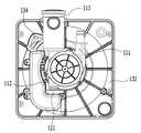
도 1은 본 발명에 따른 원심분리식 흡입장치를 설명하는 도면이다. 도 1에 도시된 바와 같이, 본 발명에 따른 원심분리식 흡입장치는 액체, 기체 또는 고체 중 어느 하나 이상의 혼합물을 유입 후 분리시키고, 혼합물에서 분리된 기체를 제1 기체배출로(112)로 배출시키는 원심분리부재(110)를 포함한다.1 is a view for explaining a centrifugal suction device according to the present invention. As shown in FIG. 1, the centrifugal suction device according to the present invention separates and mixes any one or more of liquid, gas, or solid, and discharges the gas separated from the mixture to the first gas discharge passage 112 (Not shown).
또한, 상부 면이 개방된 상태에서 내부에 제1 기체 이동로(122)를 형성하며 외 측면에 제1 기체흡입로(121)를 구비하고, 제1 기체배출로(112)와 제1 기체흡입로(121)가 연통되게 결합하는 흡입부재(120)를 포함한다.In addition, the first gas-moving
또한, 본체(131)와 하판(132)이 결합되고, 하판(132)의 일 구간에 제2 기체흡입로(133)를 형성하며, 하판(132)의 일 구간이 흡입부재(120)의 개방된 상부 면과 결합되어 제2 기체흡입로(133)가 흡입부재(120)의 내부와 연통되고, 하판(132)의 타 구간에 제2 기체배출로(134)를 형성하며, 내부에 구비된 흡입팬(135)의 회전에 의해 제2 기체흡입로(133)를 통해 흡입한 기체를 제2 기체배출로(134)로 배출시키는 진공펌프(130)를 포함한다.A second
또한, 진공펌프(130)의 하부에 설치되고, 상부의 일 구간에 제3 기체흡입로(141)를 형성하며, 제3 기체흡입로(141)가 제2 기체배출로(134)와 연통되게 결합하고, 상부의 타 구간에 제3 기체배출로(142)를 형성하며, 제3 기체흡입로(141)를 통해 흡입한 기체를 제3 기체배출로(142)를 통해 외부로 배출시키는 배출부재(140)를 포함한다.The third
도시된 바와 같이, 원심분리부재(110)는 액체, 기체 또는 고체 중 어느 하나 이상의 혼합물을 혼합물유입로(111)로 유입시킨다. 또한, 유입된 혼합물을 원심분리로 각각 분리하고, 분리된 기체를 제1 기체배출로(112)로 배출시킨다. 또한, 분리된 고체 또는 액체 중 적어도 하나를 이물질배출로(113)로 배출시킨다.As shown, the centrifugal member 110 introduces a mixture of at least one of liquid, gas, and solid into the
원심분리부재(110)는 내부에 회전팬(미도시)을 구비한다. 회전팬은 진공펌브(130)에 포함된 모터(136)의 회전축(136a)과 결합된다. 원심분리부재(110)의 회전팬은 진공펌프(130)에서 회전축(136a)의 회전에 의해 회전한다. 원심분리부재(110)는 혼합물유입로(111)를 통해 전술한 혼합물을 흡입한다.The centrifugal separator 110 has a rotary fan (not shown) therein. The rotary fan is coupled to the
원심분리부재(110)는 흡입한 혼합물을 회전력으로 원심분리하여 외부로 배출시킨다. 혼합물에서 분리된 액체 또는 고체 중 적어도 하나는 이물질배출로(113)를 통해 외부로 배출시킨다. 또한, 혼합물에서 분리된 기체는 제1 기체배출로(112)를 통해 외부로 배출시킨다. 제1 기체배출로(112)를 통해 배출되는 기체는 흡입부재(120)로 흡입된다.The centrifugal separator 110 separates the sucked mixture by centrifugal force and discharges it to the outside. At least one of the liquid or solid separated from the mixture is discharged to the outside through the foreign matter discharge path (113). Further, the gas separated from the mixture is discharged to the outside through the first gas discharge path (112). The gas discharged through the first gas discharge path (112) is sucked into the suction member (120).
원심분리부재(110)의 제1 기체배출로(112)는 흡입부재(120)의 제1 기체흡입로(121)와 결합된다. 제1 기체배출로(112)와 제1 기체흡입로(121)의 결합은 끼움결합으로 이루어진다. 본 발명은 이에 국한되지 않으며 다양한 방법을 이용해 제1 기체배출로(112)와 제1 기체흡입로(121)를 결합할 수 있다.The first
흡입부재(120)는 굴곡진 파이프(pipe)와 같은 형상으로 이루어지며, 원심분리부재(110)의 제1 기체배출로(112)와 결합되고, 진공펌프(130)의 하판(132)과 결합된다. 흡입부재(120)는 도 2에 도시된 바와 같다.The
도 2 및 도 3은 본 발명에 따른 원심분리식 흡입장치의 흡입부재(120)를 설명하는 도면이다. 흡입부재(120)는 내부에 제1 기체이동로(122)를 형성한다. 흡입부재(120)의 제1 기체이동로(122)와 연통된다. 흡입부재(120)는 절곡되게 형성되어 내부의 제1 기체 이동로(122)가 절곡된다.2 and 3 are views illustrating the
흡입부재(120)는 도 1 및 도 2에 도시된 바와 같이 상부 면이 개방되고, 개방된 상부면이 진공펌프(130)의 하판(132)에 결합된다. 흡입부재(120)의 개방된 상부 면은 하판(131)과 결합되며 덮인다. 또한, 개방된 상부 면의 일 구간이 하판(132)에 구비된 제2 기체흡입로(133)과 연통되게 결합된다.1 and 2, the upper surface of the
흡입부재(120)는 도 3에 도시된 바와 같이 하판(132)과 볼트 및 너트에 의해 결합된다. 본 발명은 이에 국한되지 않으며, 흡입부재(120)는 하판(132)과 끼움결합 등에 의해 결합될 수 있다. 도 3은 흡입부재(120)와 원심분리부재(100)가 결합된 상태에서 진공펌프(130)의 하판(132) 하부에 결합된 상태를 도시한 것이다. 도 3은 도 1에 도시된 하판(132)의 하부를 도시한 것이다.The
흡입부재(120)와 하판(132)의 결합을 위해 하판(132)은 일구간에 흡입부재(120)의 상부 면 형상과 대응되는 형상을 구비한다.The
흡입부재(120)는 원심분리부재(110)의 제1 기체배출로(112)에서 배출된 기체를 제1 기체흡입로(121)로 흡입하고, 하판(132)에 구비된 제2 기체흡입로(133)로 배출하게 된다. 기체가 흡입 및 배출되는 과정에서 기체의 이동에 의해 소음이 발생된다. 흡입부재(120)는 전술한 소음을 줄이기 위해 내측면에 제1 흡음부재(123)를 포함한다.The
제1 흡음부재(123)는 제1 기체이동로(122)를 따라 구비된다. 따라서, 흡입부재(120)에서 3면으로 이루어진 내측면에 모두 구비될 수 있고, 서로 대향하는 내측면의 2면에 구비될 수 있다.The first
흡입부재(120)의 제1 기체흡입로(121)는 외부로 연장형성되며, 원심분리부재(110)의 제1 기체배출로(112)에 끼움결합된다. 흡입부재(120)의 제1 기체흡입로(121)는 원통 형상으로 이루어진다. 제1 기체흡입로(121)는 제1 기체배출로(112)와 끼움결합됨으로, 형상은 어느 하나에 국한되지 않을 것이다. 제1 기체흡입로(121)의 형상 및 크기 등은 제1 기체배출로(112)의 형상 및 크기 등과 서로 대응될 것이다.The first
흡입부재(120)에서 개방된 상부 면의 형상은 진공펌프(130)의 하판(132)의 일 구간의 형상과 서로 대응된다. 진공펌프(130)의 하판(132)의 일 구간은 제2 기체흡입로(133)가 형성된 구간을 가리킨다.The shape of the upper surface opened in the
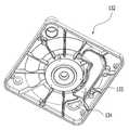
도 4 내지 도 6은 본 발명에 따른 원심분리식 흡입장치의 진공펌프를 설명하는 도면이다. 도 1 및 도 4 내지 도 6에 도시된 바와 같이, 진공펌프(130)는 본체(131)와 하판(132)이 결합된다. 본체(131)와 하판(132)의 결합에 의해 형성되는 공간에는 흡입팬(135)가 구비된다. 또한, 진공펌프(130)는 본체(131), 흡입팬(135) 및 하판(132)를 관통하는 회전축(136a)을 구비한 모터(136)를 포함한다.4 to 6 are views for explaining a vacuum pump of the centrifugal suction device according to the present invention. As shown in FIGS. 1 and 4 to 6, the
진공펌프(130)는 모터(136)의 회전축(136a)이 하부로 연장형성되어 흡입팬(135) 및 하판(132)을 관통하고, 원심분리부재(110)와 결합하여, 흡입팬(135) 및 원심분리부재(110)에 회전력을 전달한다.The
진공펌프(130)의 본체(131)는 도 1에 도시된 바와 같이 테두리 부분이 하부로 절곡되고, 절곡된 테두리 부분이 하판(132)과 결합된다. 하판(132)의 일 구간은 도 4에 도시된 바와 같이, 흡입부재(120)의 개방된 상부 면과 대응되는 형상으로 이루어진다. 흡입부재(120)의 개방된 상부 면과 대응되는 형상으로 이루어진 일 구간에는 흡입부재(120)의 제1 기체이동로(122)와 연통되는 제2 기체흡입로(133)가 형성된다.As shown in FIG. 1, the
진공펌프(130)는 하판(132)에 구비된 제2 기체흡입로(133)를 통해 흡입된 기체를 배출하는 제2 기체배출로(134)를 구비한다. 제2 기체흡입로(133)를 통해 흡입된 기체는 본체(131)와 하판(132)의 결합에 의해 형성된 내부 공간에서 이동하며 제2 기체배출로(134)로 배출된다. 원심분리부재(110)의 제1 기체배출로(112)를 통해 배출된 기체가 흡입부재(120)를 통과해 제2 기체흡입로(133)로 흡입되도록 하는 것은 모터(136)에 의한 흡입팬(135)의 회전에 의한 것이다.The
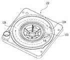
진공펌프(130)의 모터(136)에 의해 회전하는 흡입팬(135)이 흡입력을 발생시키고, 흡입팬(135)과 하판(132)의 사이 공간을 이동한 기체는 제2 기체배출로(134)를 통해 외부로 배출된다. 기체는 도 5에 도시된 제2 기체 이동로(139)를 따라 이동하여 제2 기체배출로(134)로 배출된다.The
진공펌프(130)의 하판(132)에 형성되는 제2 기체 이동로(139)는 하부로 하향 굴곡진 환형으로 이루어진다. 제2 기체 이동로(139)는 흡입팬(135)의 테두리 형상과 대응되는 형상으로 이루어지며, 흡입팬(135)의 테두리 형상은 날개(138)가 구비된 환형으로 이루어진다. 제2 기체 이동로(139)는 하부로 오목하도록 이루어지고, 제2 기체 이동로(139)를 통해 흡입부재(120)를 통과한 기체가 이동함과 동시에 흡입팬(135)의 날개(138)가 이동될 수 있는 공간을 마련해준다.The second gas passage (139) formed in the lower plate (132) of the vacuum pump (130) has a downwardly curved annular shape. The second gas-moving
도 3 내지 도 6에 도시된 바와 같이, 진공펌프(130)의 하판(132)에 형성된 제2 기체흡입로(133)는 다각형으로 이루어진다. 제2 기체흡입로(133)는 상방으로 연장형성되어 높이를 가지며 상협하광(上陜下廣)의 형상으로 이루어진다. 본 명세서에서 상방 또는 상부는 도 1을 기준으로 모터(136)가 도시된 방향을 의미하며, 하방 또는 하부는 도 1을 기준으로 배출부재(140)이 도시된 방향을 의미한다.3 to 6, the second
진공펌프(130)의 하판(132)에 형성된 제2 기체배출로(134)는 다각형으로 이루어진다. 본 발명은 이에 국한되지 않으며, 제2 기체흡입로(133) 및 제2 기체배출로(134)의 형상을 다양하게 구현할 수 있을 것이다. 진공펌프(130)의 하판(132)은 종단면 형상이 반구 형상으로 이루어진 링 형형상의 제2 기체이동로(139)를 포함한다.The second
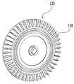
진공펌프(130)에서 흡입팬(135)은 도 6에 도시된 바와 같다. 진공펌프(130)의 흡입팬(135)은 하판(132)에 형성된 제2 기체이동로(139)와 대응되는 위치에 방사형으로 이루어진 복수의 날개(138)를 구비한다. 전술한 바와 같이 흡입팬(135)의 날개(138)는 하판(132)에 형성된 제2 기체이동로(139)의 공간에 위치하게 된다.The
따라서, 흡입팬(135)이 회전됨에 따라 기체는 흡입부재(120)를 통과해 제2 기체이동로(139)를 따라 이동한 뒤, 배출부재(140)로 이동될 수 있다. 진공펌프(130)에 의해 제2 기체이동로(139)를 이동해 제2 기체배출로(134)로 배출된 기체는 배출부재(140)의 제3 기체흡입로(141)로 유입되고, 제3 기체배출로(143)를 통해 외부로 배출된다.Accordingly, as the
도 7 및 도 8은 본 발명에 따른 원심분리식 흡입장치의 배출부재를 설명하는 도면이다. 도 7 및 도 8에 도시된 바와 같이, 배출부재(140)는 상부의 일 구간에 진공펌프(130)의 하판(132)에 형성된 제2 기체배출로(134)와 연통되게 결합되는 제3 기체 흡입로(141)를 구비한다. 또한, 배출부재(140)는 상부의 타 구간에 제3 기체 흡입로(141)와 연통되는 제4 기체배출로(142)를 구비한다.7 and 8 are views for explaining a discharge member of the centrifugal suction device according to the present invention. 7 and 8, the
제3 기체 흡입로(141)와 제4 기체배출로(142)는 도 8에 도시된 제3 기체이동로(143)를 통해 서로 연통된다. 배출부재(140)는 사각 파이프와 같은 형상으로 이루어진다. 배출부재(140)는 내벽을 따라 내부에 제3 기체 이동로(143)를 형성하며, 제3 기체흡입로(141)와 제4 기체배출로(142)가 서로 연통된다.The third
배출부재(140)는 제3 기체흡입로(141)와 제4 기체배출로(142)를 연통시키는 기체 이동통로에 제2 흡음부재(144)를 더 포함한다. 제2 흡음부재(144)는 제1 흡음부재(123)과 같이 내측면에 구비되며, 다양한 소재로 이루어질 수 있다.The
원심분리부재(110)의 제1 기체배출로(112)에서 배출된 기체는 흡입부재(120)의 제1 기체흡입로(121)를 통해 흡입부재(120)에 흡입된다. 흡입부재(120)로 흡입된 기체는 제1 기체이동로(122)를 따라 이동하여 하판(132)에 형성된 제2 기체흡입로(133)를 통해 진공펌프(130)에 흡입된다.The gas discharged from the first
진공펌프(130)에 흡입된 기체는 진공펌프(130)의 하판(132)에 구비된 제2 기체이동로(139)를 통해 이동하여 제3 기체배출로(134)로 배출된다. 제3 기체배출로(134)에서 배출된 기체는 배출부재(140)의 제3 기체흡입로(141)를 통해 배출부재(140)에 흡입된다. 배출부재(140)에 흡입된 기체는 제3 기체이동로(143)을 이동해 제4 기체배출로(142)를 거쳐 외부로 배출된다.The gas sucked into the
배출부재(140)의 상부는 진공펌프(130)의 하판(132)에 원심분리부재(110), 흡입부재(120)와 함께 결합된다. 결합은 볼드 및 너트에 의해 결합된다. 본 발명에서 결합은 다양한 방법으로 이루어질 수 있다. 배출부재(140)의 상부가 진공펌프(130)의 하판(132)에 결합될 때, 원심분리부재(110) 및 흡입부재(120)는 배출부재(140)의 중앙부분에 배치된다. 배출부재(140)의 중앙부분에 원심분리부재(110) 및 흡입부재(120)가 배치되는 것은 배출부재(140)가 사각 파이프의 형상으로 이루어지기 때문에 가능하다.The upper portion of the
전술한 바와 같이, 본 발명에 따른 원심분리식 흡입장치는 액체, 기체 또는 고체 중 어느 하나 이상의 혼합물을 분리시키고, 분리된 기체를 배출시키는 원심분리부재(110)와 연통되게 결합되는 흡입부재(120)를 구비하고, 흡입부재(120)에 제1 흡음부재(123)가 포함되며 절곡되게 형성되며, 흡입부재(120)를 통과한 기체가 진공펌프(130)에 유입됨으로써, 액체, 기체 및 고체의 혼합물을 원심분리로 각각 분리한 후, 분리된 기체를 흡입팬으로 흡입하는 과정에서 발생되는 흡입소음을 최소화할 수 있다.As described above, the centrifugal suction device according to the present invention includes a suction member 120 (not shown) connected to the centrifugal separator 110 for separating a mixture of liquid, gas, or solid and discharging the separated gas, And a first
또한, 원심분리부재(110)에서 분리된 기체가 흡입부재(120)를 통과해 1차 흡음된 후 진공펌프(130)에 유입되고, 진공펌프(130)에서 배출되는 기체가 배출부재(140)에 유입되어 2차 흡음된 후 외부에 배출됨으로써, 혼합물에서 분리된 기체를 흡입팬으로 흡입한 후, 흡인한 기체를 외부로 배출하는 과정에서 발생되는 배출소음을 최소화할 수 있다.The gas separated from the centrifugal separator 110 passes through the
본 실시 예 및 본 명세서에 첨부된 도면은 본 발명에 포함되는 기술적 사상의 일부를 명확하게 나타내고 있는 것에 불과하며, 본 발명의 명세서 및 도면에 포함된 기술적 사상의 범위 내에서 당업자가 용이하게 유추할 수 있는 변형 예와 구체적인 실시 예는 모두 본 발명의 권리범위에 포함되는 것이 자명하다고 할 것이다.It is to be understood that both the foregoing general description and the following detailed description of the present invention are exemplary and explanatory and are intended to provide further explanation of the invention as claimed. It will be understood that variations and specific embodiments which may occur to those skilled in the art are included within the scope of the present invention.
110: 원심분리부재111: 혼합물유입로
112: 제1 기체배출로113: 이물질배출로
120: 흡입부재121: 제1 기체흡입로
122: 제1 기체 이동로123: 제1 흡음부재
130: 진공펌프131: 본체
132: 하판133: 제2 기체흡입로
134: 제2 기체배출로135: 흡입팬
136: 모터136a: 회전축
138: 날개139: 제2 기체 이동로
140: 배출부재141: 제3 기체흡입로
142: 제3 기체배출로143: 제3 기체 이동로
144: 제2 흡음부재110: centrifugal separator 111: mixture inlet
112: first gas discharge path 113: foreign matter discharge path
120: suction member 121: first gas suction path
122: first gas moving path 123: first sound absorbing member
130: Vacuum pump 131: Body
132: lower plate 133: second gas suction path
134: Second gas exhaust path 135: Suction fan
136:
138: wing 139: second gas moving path
140: exhaust member 141: third gas suction path
142: third gas discharge passage 143: third gas passage
144: second sound absorbing member
Claims (14)
Translated fromKorean진공펌프는 모터의 회전축이 하부로 연장형성되어 흡입팬 및 하판을 관통하고, 원심분리부재와 결합하여, 흡입팬 및 원심분리부재에 회전력을 전달하는 것을 특징으로 하는 원심분리식 흡입장치.A centrifugal member for separating and introducing a mixture of at least one of liquid, gas and solid, and discharging the separated gas from the mixture to the first gas discharge path; A suction member which forms a first gas flow path in an opened state with the upper surface thereof opened and has a first gas suction path on an outer surface thereof and which connects the first gas discharge path and the first gas suction path in communication; The main body and the lower plate are coupled and the second gas suction passage is formed in one section of the lower plate and the one section of the lower plate is engaged with the open upper surface of the suction member so that the second gas suction passage is communicated with the inside of the suction member A vacuum pump which forms a second gas exhaust passage in another section of the lower plate and discharges the gas sucked through the second gas suction passage to the second gas discharge passage by the rotation of the suction fan provided therein; And a third gas suction path provided in a lower portion of the vacuum pump and connected to the third gas suction path so as to communicate with the second gas discharge path, And a discharge member for discharging the gas sucked through the third gas suction path to the outside through the third gas discharge path,
Wherein the vacuum pump has a rotation axis of the motor extending downward to penetrate through the suction fan and the lower plate and coupled with the centrifugal member to transmit rotational force to the suction fan and the centrifugal separator.
흡입부재의 제1 기체흡입로와 내부에 형성된 제1 기체이동로는 서로 연통되는 것을 특징으로 하는 원심분리식 흡입장치.The method according to claim 1,
Wherein the first gas suction path of the suction member and the first gas flow path formed therein communicate with each other.
흡입부재는 절곡되게 형성되어 내부의 제1 기체이동로가 절곡된 것을 특징으로 하는 원심분리식 흡입장치.The method according to claim 1,
Wherein the suction member is formed to be bent so that the first gas-moving path therein is bent.
흡입부재는 내측면에 제1 흡음부재를 더 포함하는 것을 특징으로 하는 원심분리식 흡입장치.The method according to claim 1,
Wherein the suction member further comprises a first sound-absorbing member on an inner surface thereof.
흡입부재의 제1 기체흡입로는 외부로 연장형성되며, 원심분리부재의 제1 기체배출로에 끼움결합되는 것을 특징으로 하는 원심분리식 흡입장치.The method according to claim 1,
Wherein the first gas suction path of the suction member extends to the outside and is fitted to the first gas discharge path of the centrifugal member.
흡입부재에서 개방된 상부 면의 형상은 제2 기체흡입로가 형성된 하판의 일 구간의 형상과 서로 대응되는 것을 특징으로 하는 원심분리식 흡입장치.The method according to claim 1,
Wherein the shape of the upper surface opened in the suction member corresponds to the shape of one section of the lower plate formed with the second gas suction path.
진공펌프의 하판에 형성된 제2 기체흡입로는 다각형으로 이루어진 것을 특징으로 하는 원심분리식 흡입장치.The method according to claim 1,
Wherein the second gas suction path formed on the lower plate of the vacuum pump is formed in a polygonal shape.
제2 기체흡입로는 상방으로 연장형성되어 높이를 가지며 상협하광(上陜下廣)의 형상으로 이루어진 것을 특징으로 하는 원심분리식 흡입장치.9. The method of claim 8,
Wherein the second gas suction path extends upward and has a height and has a shape of a vertically downward light.
진공펌프의 하판에 형성된 제2 기체배출로는 다각형으로 이루어진 것을 특징으로 하는 원심분리식 흡입장치.The method according to claim 1,
Wherein the second gas discharge passage formed in the lower plate of the vacuum pump is formed in a polygonal shape.
진공펌프의 하판은 종단면 형상이 반구 형상으로 이루어진 링 방식의 제2 기체이동로를 형성하는 것을 특징으로 하는 원심분리식 흡입장치.The method according to claim 1,
Wherein the lower plate of the vacuum pump forms a ring-shaped second gas-moving passage having a semi-spherical shape in longitudinal section.
진공펌프의 흡입팬은 하판에 형성된 제2 기체이동로와 대응되는 위치에 복수의 날개를 방사형으로 구비하는 것을 특징으로 하는 원심분리식 흡입장치.12. The method of claim 11,
Wherein the suction fan of the vacuum pump is provided with a plurality of vanes radially at positions corresponding to the second gas passage formed in the lower plate.
배출부재는 내벽을 따라 내부에 제3 기체이동로를 형성하며, 제3 기체흡입로와 제4 기체배출로가 서로 연통되는 것을 특징으로 하는 원심분리식 흡입장치.The method according to claim 1,
Wherein the discharge member forms a third gas passage along the inner wall, and the third gas suction passage and the fourth gas discharge passage communicate with each other.
배출부재는 제3 기체흡입로와 제4 기체배출로를 연통시키는 기체 이동통로에 제2 흡음부재를 더 포함하는 것을 특징으로 하는 원심분리식 흡입장치.13. The method of claim 12,
Wherein the discharge member further comprises a second sound-absorbing member in a gas-moving path communicating the third gas-suction path and the fourth gas-discharge path.
Priority Applications (1)
| Application Number | Priority Date | Filing Date | Title |
|---|---|---|---|
| KR20130109596AKR101498016B1 (en) | 2013-09-12 | 2013-09-12 | Apparatus for suction of centrifugation type |
Applications Claiming Priority (1)
| Application Number | Priority Date | Filing Date | Title |
|---|---|---|---|
| KR20130109596AKR101498016B1 (en) | 2013-09-12 | 2013-09-12 | Apparatus for suction of centrifugation type |
Publications (1)
| Publication Number | Publication Date |
|---|---|
| KR101498016B1true KR101498016B1 (en) | 2015-03-09 |
Family
ID=53026051
Family Applications (1)
| Application Number | Title | Priority Date | Filing Date |
|---|---|---|---|
| KR20130109596AActiveKR101498016B1 (en) | 2013-09-12 | 2013-09-12 | Apparatus for suction of centrifugation type |
Country Status (1)
| Country | Link |
|---|---|
| KR (1) | KR101498016B1 (en) |
Citations (4)
| Publication number | Priority date | Publication date | Assignee | Title |
|---|---|---|---|---|
| US4824333A (en)* | 1985-10-01 | 1989-04-25 | Rexair, Inc. | Air blower assembly for vacuum cleaners |
| KR20090007348A (en)* | 2006-03-28 | 2009-01-16 | 두르 덴탈 게엠베하 & 씨오. 케이쥐이 | Suction machine |
| KR20100001005A (en)* | 2008-06-26 | 2010-01-06 | 주식회사 한랩 | Low-noise cooling unit for a centrifuge |
| US20120308361A1 (en)* | 2010-02-15 | 2012-12-06 | E.M.B. Di Bergamaschini Alfonso | Centrifugal electric pump for suction of aeriform fluids with silencing device |
- 2013
- 2013-09-12KRKR20130109596Apatent/KR101498016B1/enactiveActive
Patent Citations (4)
| Publication number | Priority date | Publication date | Assignee | Title |
|---|---|---|---|---|
| US4824333A (en)* | 1985-10-01 | 1989-04-25 | Rexair, Inc. | Air blower assembly for vacuum cleaners |
| KR20090007348A (en)* | 2006-03-28 | 2009-01-16 | 두르 덴탈 게엠베하 & 씨오. 케이쥐이 | Suction machine |
| KR20100001005A (en)* | 2008-06-26 | 2010-01-06 | 주식회사 한랩 | Low-noise cooling unit for a centrifuge |
| US20120308361A1 (en)* | 2010-02-15 | 2012-12-06 | E.M.B. Di Bergamaschini Alfonso | Centrifugal electric pump for suction of aeriform fluids with silencing device |
Similar Documents
| Publication | Publication Date | Title |
|---|---|---|
| KR100594194B1 (en) | Cyclone Dust Collector for Vacuum Cleaner | |
| KR100437364B1 (en) | Cyclone dust-collecting apparatus for Vaccum Cleaner | |
| CN1839744B (en) | Cyclone dust separating apparatus for vacuum cleaner and the vacuum cleaner | |
| KR100530359B1 (en) | A attaching/disattaching device for contaminant collecting receptacle of cyclone separator | |
| CA1336268C (en) | Process and apparatus for separating solids and liquids from an effluent stream | |
| JPWO2019064862A1 (en) | Collection device and detection device | |
| EP0728435A1 (en) | Cyclone dust extractor | |
| KR20020009768A (en) | Cyclone dust-collecting apparatus for Vaccum Cleaner | |
| JP2007117713A (en) | Vacuum cleaner dust collector | |
| EP1683463A3 (en) | Cyclonic separating apparatus for vacuum cleaner which is capable of separately collecting water from dust | |
| RU2264781C2 (en) | Cyclone vacuum cleaner and manipulation pipe for it | |
| CA2388157A1 (en) | Grill assembly of a cyclone dust collecting apparatus for a vacuum cleaner | |
| JP2000157463A (en) | Cyclone dust collector for vacuum cleaner | |
| CN101612025A (en) | Cyclone dust collector | |
| JPWO2019064861A1 (en) | Detection device | |
| CN1744843A (en) | Cyclone Separators for Vacuum Cleaners | |
| AU2015201184A1 (en) | Cyclonic separation device | |
| JP2018108351A (en) | Automatic dry suction device for dental unit chair | |
| KR101641257B1 (en) | Dust collector for a vacuum cleaner | |
| KR101498016B1 (en) | Apparatus for suction of centrifugation type | |
| CN219089080U (en) | Dust cup assembly and cleaning equipment | |
| CN116327030B (en) | Dust cup components and cleaning equipment | |
| KR101421530B1 (en) | Apparatus for centrifugation with separation foreign substance of dentistry | |
| KR20180050552A (en) | Electrostatic type cyclone dust collector for cleaner | |
| JPH07171072A (en) | Method and device for circulation cleaning |
Legal Events
| Date | Code | Title | Description |
|---|---|---|---|
| PA0109 | Patent application | Patent event code:PA01091R01D Comment text:Patent Application Patent event date:20130912 | |
| PA0201 | Request for examination | ||
| PE0902 | Notice of grounds for rejection | Comment text:Notification of reason for refusal Patent event date:20141127 Patent event code:PE09021S01D | |
| E701 | Decision to grant or registration of patent right | ||
| PE0701 | Decision of registration | Patent event code:PE07011S01D Comment text:Decision to Grant Registration Patent event date:20150130 | |
| GRNT | Written decision to grant | ||
| PR0701 | Registration of establishment | Comment text:Registration of Establishment Patent event date:20150225 Patent event code:PR07011E01D | |
| PR1002 | Payment of registration fee | Payment date:20150225 End annual number:3 Start annual number:1 | |
| PG1601 | Publication of registration | ||
| FPAY | Annual fee payment | Payment date:20180115 Year of fee payment:4 | |
| PR1001 | Payment of annual fee | Payment date:20180115 Start annual number:4 End annual number:4 | |
| FPAY | Annual fee payment | Payment date:20200109 Year of fee payment:6 | |
| PR1001 | Payment of annual fee | Payment date:20200109 Start annual number:6 End annual number:6 | |
| PR1001 | Payment of annual fee | Payment date:20210202 Start annual number:7 End annual number:7 | |
| PR1001 | Payment of annual fee | Payment date:20220208 Start annual number:8 End annual number:8 | |
| PR1001 | Payment of annual fee | Payment date:20230213 Start annual number:9 End annual number:9 | |
| PR1001 | Payment of annual fee | Payment date:20240226 Start annual number:10 End annual number:10 | |
| PR1001 | Payment of annual fee | Payment date:20250225 Start annual number:11 End annual number:11 |