KR101496408B1 - Full color holographic optical element and method for fabricating the same using photopolymer, waveguide-type head mounted display - Google Patents
Full color holographic optical element and method for fabricating the same using photopolymer, waveguide-type head mounted displayDownload PDFInfo
- Publication number
- KR101496408B1 KR101496408B1KR20130056251AKR20130056251AKR101496408B1KR 101496408 B1KR101496408 B1KR 101496408B1KR 20130056251 AKR20130056251 AKR 20130056251AKR 20130056251 AKR20130056251 AKR 20130056251AKR 101496408 B1KR101496408 B1KR 101496408B1
- Authority
- KR
- South Korea
- Prior art keywords
- photopolymer
- light
- optical element
- full
- holographic optical
- Prior art date
- Legal status (The legal status is an assumption and is not a legal conclusion. Google has not performed a legal analysis and makes no representation as to the accuracy of the status listed.)
- Expired - Fee Related
Links
Images


Classifications
- G—PHYSICS
- G02—OPTICS
- G02B—OPTICAL ELEMENTS, SYSTEMS OR APPARATUS
- G02B27/00—Optical systems or apparatus not provided for by any of the groups G02B1/00 - G02B26/00, G02B30/00
- G02B27/01—Head-up displays
- G02B27/017—Head mounted
- G02B27/0172—Head mounted characterised by optical features
- G—PHYSICS
- G02—OPTICS
- G02B—OPTICAL ELEMENTS, SYSTEMS OR APPARATUS
- G02B27/00—Optical systems or apparatus not provided for by any of the groups G02B1/00 - G02B26/00, G02B30/00
- G02B27/01—Head-up displays
- G02B27/0101—Head-up displays characterised by optical features
- G—PHYSICS
- G02—OPTICS
- G02B—OPTICAL ELEMENTS, SYSTEMS OR APPARATUS
- G02B27/00—Optical systems or apparatus not provided for by any of the groups G02B1/00 - G02B26/00, G02B30/00
- G02B27/01—Head-up displays
- G02B27/0101—Head-up displays characterised by optical features
- G02B27/0103—Head-up displays characterised by optical features comprising holographic elements
- G02B2027/0109—Head-up displays characterised by optical features comprising holographic elements comprising details concerning the making of holograms
- G—PHYSICS
- G02—OPTICS
- G02B—OPTICAL ELEMENTS, SYSTEMS OR APPARATUS
- G02B27/00—Optical systems or apparatus not provided for by any of the groups G02B1/00 - G02B26/00, G02B30/00
- G02B27/01—Head-up displays
- G02B27/017—Head mounted
- G02B27/0172—Head mounted characterised by optical features
- G02B2027/0174—Head mounted characterised by optical features holographic
Landscapes
- Physics & Mathematics (AREA)
- General Physics & Mathematics (AREA)
- Optics & Photonics (AREA)
- Diffracting Gratings Or Hologram Optical Elements (AREA)
Abstract
Translated fromKoreanDescription
Translated fromKorean본 발명은 풀 컬러 홀로그래픽 광학소자 및 표시장치에 관한 것으로, 더욱 상세하게는 포토폴리머를 사용하여 풀 컬러 홀로그래픽 광학소자를 제작하고, 이를 도파관(Waveguide) 타입 HMD에 적용한 포토폴리머를 이용한 풀 컬러 홀로그래픽 광학소자 및 이의 제조방법과, 표시장치에 관한 것이다.
BACKGROUND OF THE
HMD(Head Mounted Display)는 안경 또는 헬멧처럼 머리에 쓰고 대형 영상을 즐길 수 있는 영상표시장치이며, 1인치 이하의 패널을 여러 개의 광학계를 통해 확대하여 가상의 이미지를 제공하도록 구성되어 있다.The HMD (Head Mounted Display) is a video display device that can be used for a large image on a head like a pair of glasses or a helmet, and is configured to provide a virtual image by enlarging a panel of one inch or less through a plurality of optical systems.
이와 같이, HMD는 영상을 광학계를 통해서 대형화면으로 볼 수 있으므로, HMD 내부의 광학계들에 대한 개발이 무엇보다 중요하다. 광학계를 사용하여 가상화면을 구현할 수 있도록 동공의 크기, 가상이미지를 보기 위한 광학계와 눈까지의 거리(Eye Relief), 확대 배율, 화각(FOV) 등을 고려하여 광학계를 설계하려면 많은 렌즈 미러(Mirror), 하프 미러(Half Mirror)와 같은 광학소자들이 내설됨으로 인해 부피가 커지고 무거울 뿐 아니라, 좁은 공간 내에 여러 소자를 장착해야 하므로 공정이 까다롭다는 단점이 있다[1 ~ 3].
As described above, since the HMD can be viewed as a large screen through the optical system, development of the optical systems inside the HMD is most important. In order to design the optical system considering the optical system for viewing the pupil size and virtual image, eye relief, enlargement magnification, and angle of view (FOV) so that a virtual screen can be implemented using the optical system, many lens mirrors ) And half mirrors, which are bulky and heavier due to the presence of optical elements such as a half mirror [1] and [3].
한편, 홀로그래픽 광학소자(Holographic Optical Element : HOE)를 HMD 시스템에 적용하면, 광학소자의 매수가 현저히 줄어들기 때문에 좁은 공간에 시스템을 용이하게 구성할 수 있을 뿐 아니라, 기존의 HMD 시스템보다 상당히 가볍다는 장점이 있다[4, 5].On the other hand, when a holographic optical element (HOE) is applied to an HMD system, since the number of optical elements is significantly reduced, the system can be easily configured in a narrow space and is significantly lighter than a conventional HMD system , Which has the advantage of [4, 5].
T. Ando et al.이 HOE를 이용하여 HMD를 제작하는 것을 제안한 바 있다[6]. 그러나 이 방법은 부피를 줄이는데 한계가 있다. 즉, 도파관(Waveguide) 타입이 아니기 때문에 안경형식으로 이용할 수 없다.T. Ando et al. Proposed to fabricate an HMD using this HOE [6]. However, this method has limitations in reducing volume. That is, since it is not a waveguide type, it can not be used in the form of glasses.
이에 Y. Amitai et al.와 I. Kasai et al.가 안경형 디스플레이를 제안하였으나, 이는 홀로그램 격자를 사용하고 있다[7, 8]. 이 방식은 사이즈는 줄일 수는 있지만 회절효율이 낮다. 또한 풀 컬러도 제공하지 않는다.Y. Amitai et al. And I. Kasai et al. Proposed a spectacular display, which uses a holographic grating [7, 8]. This method can reduce the size but has low diffraction efficiency. It also does not offer full color.
이에 H. Mukawa et al.가 풀 컬러 안경형 디스플레이(Full Color Eyewear Display)를 제안한 바 있다[9]. 그러나, 이 또한 컬러 균일도의 문제점이 존재한다.
H. Mukawa et al. Proposed a full color eyewear display [9]. However, this also poses a problem of color uniformity.
한편, 다양한 장점을 갖는 포토폴리머 특성상, 광학소자[10, 11], holographic storage[12], holographic display[13] 등에 많이 응용되고 있으며, 포토폴리머의 광학특성에 대해 많은 연구가 진행되고 있다[14]. 그러나 이러한 응용에 있어, 포토폴리머의 단색에 대한 특성만 분석되고 있을 뿐, 풀 컬러에 대해 분석은 아직까지 수행되지 못하고 있다.
On the other hand, due to the properties of photopolymers with various advantages, they are widely applied to optical devices [10, 11], holographic storage [12], and holographic displays [13] ]. In this application, however, only the characteristics of the photopolymer in terms of monochromaticity are analyzed, and analysis of full color has not yet been performed.
따라서, 본 발명은 상기한 종래 기술의 문제점을 해결하기 위해 이루어진 것으로서, 본 발명의 목적은 빛의 세기에 따른 굴절률 변화로 영상을 기록하는데 높은 회절효율을 가지며 또한 화학처리 없이 건조처리만으로 쉽게 홀로그램을 제작할 수 있고, 높은 신뢰성, 고분해능 등의 장점을 갖는 포토폴리머를 이용하여 풀 컬러 홀로그래픽 광학소자를 제작하고, 이를 도파관(Waveguide) 타입 HMD에 적용할 수 있는 포토폴리머를 이용한 풀 컬러 홀로그래픽 광학소자 및 이의 제조방법과, 표시장치를 제공하는데 있다.
It is therefore an object of the present invention to provide a hologram recording apparatus and a hologram recording method which have a high diffraction efficiency in recording an image due to a change in refractive index according to the intensity of light, Color holographic optical element using a photopolymer having advantages such as high reliability and high resolution and to apply it to a waveguide type HMD, a full-color holographic optical element A method of manufacturing the same, and a display device.
상기와 같은 목적을 달성하기 위한 본 발명의 포토폴리머를 이용한 풀 컬러 홀로그래픽 광학소자의 제조방법은, (a) 제1포토폴리머에 참조 빔(Reference Beam)을 입사시키고, 상기 제1포토폴리머에 상기 참조 빔에 설정 각으로 적색 레이저의 물체 빔(Object Beam)을 입사시켜 적색광용 포토폴리머를 형성시키는 단계; 및 (b) 제2포토폴리머에 상기 참조 빔을 입사시키고, 상기 제2포토폴리머에 상기 참조 빔에 설정각으로 녹색 레이저와 청색 레이저가 합쳐진 물체 빔(Object Beam)을 입사시켜 녹색 및 청색광용 포토폴리머를 형성시키는 단계를 포함하는 것을 특징으로 한다.According to an aspect of the present invention, there is provided a method of manufacturing a full color holographic optical element using a photopolymer, the method comprising: (a) introducing a reference beam into a first photopolymer; Introducing an object beam of a red laser into the reference beam at a predetermined angle to form a red light photopolymer; (B) introducing the reference beam into the second photopolymer, introducing an object beam into the second photopolymer into which the green laser and the blue laser are incident at a predetermined angle, And forming a polymer.
상기 참조 빔은 상기 제1포토폴리머 또는 제2포토폴리머에 부착된 도광판(Light Guide Plate)을 경유하며, 상기 물체 빔은 상기 제1포토폴리머 또는 제2포토폴리머에 부착된 상기 설정각으로 회절시키는 프리즘을 경유한다. 이때, 상기 설정각은 40° ~ 60° 인 것이 바람직하며, 상기 설정각이 55° 인 것이 가장 바람직하다.The reference beam passes through a light guide plate attached to the first photopolymer or the second photopolymer and diffracts the object beam to the first photopolymer or the set angle attached to the second photopolymer Via a prism. At this time, the setting angle is preferably 40 ° to 60 °, and the setting angle is most preferably 55 °.
상기 단계 (a) 및 (b)는, 상기 물체 빔 조사 후, 강도 350μW/㎠의 자외선을 1 ~ 5분간 조사하는 단계를 더 포함할 수 있으며, 상기 단계 (a)와 단계 (b) 사이에, 상기 적색광용 포토폴리머를 건조시키는 단계를 더 포함할 수 있다.The step (a) and the step (b) may further include irradiating ultraviolet rays having an intensity of 350 μW /
상기 적색광용 포토폴리머에 상기 제2포토폴리머를 적층시켜 상기 단계 (b)를 진행할 수 있다.
The second photopolymer may be laminated on the red light photopolymer and the step (b) may be performed.
한편, 본 발명은 상기한 제조방법에 의해 제조된 결과물로서, 적색광용 포토폴리머와 녹색 및 적색광용 포토폴리머를 적층한 풀 컬러 홀로그래픽 광학소자를 특징으로 한다.
In the meantime, the present invention is a full color holographic optical element obtained by laminating a photopolymer for red light and a photopolymer for green and red light, as a result of the above production method.
한편, 본 발명의 포토폴리머를 이용한 풀 컬러 홀로그래픽 광학소자를 갖는 표시장치는, 소스 영상을 출력하는 디스플레이; 상기 디스플레이를 시준하는 시준 렌즈; 상기 시준 렌즈를 통과한 광을 회절시키는 상기한 방법으로 제조된 풀 컬러 홀로그래픽 광학소자를 갖는 커플 인 광학계(Couple in Optics); 회절된 광을 전반사시켜 유도하는 도광판(Light Guide Plate); 및 상기 도광판을 통해 유도된 회절된 광을 출력시키는 상기한 방법으로 제조된 풀 컬러 홀로그래픽 광학소자를 갖는 커플 아웃 광학계(Couple out Optics)를 포함하는 것을 특징으로 한다.Meanwhile, a display device having a full-color holographic optical element using the photopolymer of the present invention includes: a display for outputting a source image; A collimating lens for collimating the display; An optical system (Couple in Optics) which is a couple having a full-color holographic optical element manufactured by the above-described method of diffracting light passing through the collimating lens; A light guide plate for guiding the diffracted light by total reflection; And a coupling-out optical system having a full-color holographic optical element manufactured by the above-described method for outputting the diffracted light led through the light guide plate.
상기 포토폴리머를 이용한 풀 컬러 홀로그래픽 광학소자를 갖는 표시장치는 안경형 표시장치로서 적용될 수 있다.
The display device having the full-color holographic optical element using the photopolymer can be applied as a spectacles-type display device.
상술한 바와 같이, 본 발명에 의한 포토폴리머를 이용한 풀 컬러 홀로그래픽 광학소자 및 이의 제조방법과, 표시장치에 따르면, 도파관 타입으로 형성된 HMD용 표시장치는 도광판의 사이즈를 임의로 줄일 수 있으므로 사람이 착용하기에 거부감이 없는 안경형 디스플레이로의 제작이 용이하다.
As described above, according to the full-color holographic optical element using the photopolymer according to the present invention, the manufacturing method thereof, and the display apparatus, since the size of the light guide plate can be arbitrarily reduced, It is easy to manufacture a spectacular display having no sense of resistance.
도 1은 본 발명의 일실시예에 의한 HMD용 표시장치의 구성도이다.
도 2는 HOE 기록을 위한 개념도이다.
도 3은 포토폴리머의 광학특성분석을 위한 실험 셋업이다.
도 4는 회절효율을 측정한 결과 그래프이다.
도 5는 입사각도에 따른 포토폴리머의 회절효율 분포도이다.
도 6은 각도 선택성에 따른 포토폴리머의 회절효율 분포도이다.
도 7은 기록각도에 따른 수축률을 나타낸 그래프이다.
도 8은 풀 컬러 HOE를 제작하기 위한 실험 셋업이다.
도 9는 단색 HMD용 HOE의 출력 효율을 나타낸 도면이다.
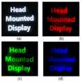
도 10은 단색 HOE를 HMD용 표시장치에 적용한 결과 영상이다.
도 11은 도 10의 couple out 측에서 카메라로 캡쳐한 RGB 컬러에 대한 출력 영상이다.
도 12는 한 장의 포토폴리머를 이용한 풀 컬러 HOE의 출력효율 결과이다.
도 13은 3층 적층의 포토폴리머를 이용한 풀 컬러 HOE의 출력효율 결과이다.
도 14는 2층 적층의 포토폴리머를 이용한 풀 컬러 HOE의 출력효율 결과이다.
도 15는 풀 컬러 HOE를 HMD용 표시장치에 적용한 결과 영상이다.
도 16은 도 15의 couple out 측에서 카메라로 캡쳐한 RGB 컬러에 대한 출력 영상이다.1 is a configuration diagram of a display device for an HMD according to an embodiment of the present invention.
2 is a conceptual diagram for HOE recording.
Figure 3 is an experimental setup for optical characterization of photopolymers.
FIG. 4 is a graph showing the diffraction efficiency measured.
5 is a diffraction efficiency distribution diagram of a photopolymer according to an incident angle.
6 is a diffraction efficiency distribution diagram of the photopolymer according to the angle selectivity.
7 is a graph showing the shrinkage ratio according to the recording angle.
Figure 8 is an experimental setup for making a full color HOE.
9 is a diagram showing the output efficiency of the HOE for a monochrome HMD.
10 is a result image obtained by applying a monochrome HOE to a display device for an HMD.
11 is an output image of the RGB color captured by the camera at the couple out side of FIG.
12 shows the output efficiency results of a full-color HOE using a single photopolymer.
13 shows the output efficiency results of a full color HOE using a three-layer laminated photopolymer.
Fig. 14 shows the output efficiency results of a full-color HOE using a two-layer laminated photopolymer.
FIG. 15 is a result image obtained by applying the full-color HOE to a display device for an HMD.
16 is an output image of the RGB color captured by the camera at the couple out side in FIG.
먼저, 본 발명은 홀로그램 기록 매질인 포토폴리머를 이용하여 도파관(Waveguide) 타입 HMD(Head Mounted Display)용 풀 컬러 홀로그래픽 광학소자(Full Color HOE(Holographic Optical Element))를 제작하기 위한 것이다.First, the present invention is for producing a full color holographic optical element (HOE) for a waveguide type HMD (Head Mounted Display) using a photopolymer as a hologram recording medium.
이를 위해 본 발명에서는 HOE의 기록매질인 포토폴리머의 R, G, B 각 컬러에 대한 전반적인 광학특성을 분석한다. 분석결과, 포토폴리머는 R, G, B 각 레이저에 대해 97%의 높은 회절효율을 나타내고, 여러 다양한 각도에서도 90% 이상의 회절효율을 나타내는 것을 확인하였다. 또한 비교적 넓은 각도 선택성을 가지며, 수축률은 각의 컬러에 대해 약 1.2%, 1.3%, 1.2%로 비슷하게 나타나는 것을 확인하였다.For this purpose, the present invention analyzes the overall optical characteristics of the R, G and B colors of the photopolymer which is the recording medium of the HOE. As a result of the analysis, the photopolymer exhibited a high diffraction efficiency of 97% for each of the R, G and B lasers, and showed a diffraction efficiency of 90% or more even at various angles. Also, it has a relatively wide angular selectivity, and the shrinkage ratio is about 1.2%, 1.3%, and 1.2% for each color.
이와 같이, 포토폴리머의 특성분석 데이터를 바탕으로 풀 컬러 HOE의 제작에 필요한 최적의 기록조건을 찾고, 풀 컬러 표현 방법에 대해 다양한 시도를 통해 2층 적층구조가 가장 효율적인 HOE의 제작 방법임을 확인하였다.
In this way, based on the characteristics analysis data of the photopolymer, the optimum recording conditions necessary for the production of full-color HOEs were searched and various attempts were made to express the full color, and it was confirmed that the two-layer laminated structure is the most efficient method of manufacturing the HOE .
이하, 본 발명의 포토폴리머를 이용한 풀 컬러 홀로그래픽 광학소자 및 이의 제조방법과, 표시장치에 대하여 첨부된 도면을 참조하여 상세히 설명하기로 한다.Hereinafter, a full-color holographic optical element using the photopolymer of the present invention, a method of manufacturing the same, and a display device will be described in detail with reference to the accompanying drawings.
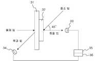
도 1은 본 발명의 일실시예에 의한 HMD용 표시장치의 구성도이다.1 is a configuration diagram of a display device for an HMD according to an embodiment of the present invention.
도 1을 참조하면, 본 발명의 HMD용 표시장치는, 소스 영상을 출력하는 마이크로 디스플레이(Micro Display)(11)와, 마이크로 디스플레이(11)를 시준하는 시준 렌즈(12)와, 시준 렌즈(12)를 통과한 광을 회절시키는 커플 인 광학계(Couple in Optics)(13)와, 회절된 광을 전반사시켜 유도하는 도광판(Light Guide Plate ; 유리 기판)(14)과, 도광판(14)을 통해 유도된 회절된 광을 출력시키는 커플 아웃 광학계(Couple out Optics)(15)를 포함한다.1, a display device for an HMD according to the present invention includes a
커플 인 광학계와 커플 아웃 광학계는 도광판(14)의 양측에 형성되며, 커플 인 광학계와 커플 아웃 광학계는 본 발명에서 제시하는 풀 컬러 홀로그래픽 광학소자로 구성한다.The couple optical system and the coupling-out optical system are formed on both sides of the
이와 같이 도파관 타입으로 형성된 HMD용 표시장치는 도광판(14)의 사이즈를 임의로 줄일 수 있으므로 사람이 착용하기에 거부감이 없는 안경형 디스플레이로의 제작이 용이하다는 장점이 있다.Since the HMD display device formed in the waveguide type can reduce the size of the
한편, 도 1에서 α는 HOE의 회절각도이다. 도광판(14) 내부에서의 전반사를 통해 광이 전파하므로 식(1)의 스넬 법칙에 따라,On the other hand, in Fig. 1,? Is the diffraction angle of the HOE. According to the Snell's law of equation (1), light propagates through total internal reflection in the

이다. 여기서, 도광판(14)의 굴절률은


또한, 본 발명의 HMD용 표시장치에 포토폴리머를 적용하려면, 기록시 공기 중에서 90° 이상의 빔을 포토폴리머에 입사하여야만 포토폴리머의 내부에서 42° 이상의 회절 각도를 만족시킨다. 이는 시스템적으로 기록이 불가능하기 때문에, 도 2와 같이 프리즘을 이용해 참조 빔과 물체 빔을 입사시킨다.
Further, in order to apply the photopolymer to the HMD display device of the present invention, a beam of at least 90 degrees in air at the time of recording must be incident on the photopolymer to satisfy the diffraction angle of 42 degrees or more inside the photopolymer. Since it is impossible to systematically record, the reference beam and the object beam are incident using a prism as shown in FIG.
도 2는 HOE 기록을 위한 개념도이다.2 is a conceptual diagram for HOE recording.
도 2를 참조하면, 기록유닛(2)은 포토폴리머(21) 양측으로 제1프리즘(22)과 제2프리즘(23)을 형성시키고 있다.Referring to FIG. 2, the
도광판(도 1의 14)을 통하여 제1프리즘(22)으로 포토폴리머(21)에 수평방향으로 참조 빔(reference beam)을 입사시키고, 제2프리즘(23)을 통하여 포토폴리머에 참조 빔과 40° ~ 60°(바람직하게 55°의 각도)를 이루도록 물체 빔을 입사시킨다.
A reference beam is horizontally incident on the
한편, 포토폴리머의 광학적 특성은 홀로그램 격자 제작에 있어 중요한 기초 데이터를 제공한다. 특성분석을 위한 광학 셋업으로부터 포토폴리머의 R, G, B 각 컬러에 대한 에너지에 따른 회절효율, 입사각도에 따른 회절효율, 각도선택성에 따른 특성, 수축에 따른 광학 특성 등을 분석하며, 특성 분석결과로부터 최적의 기록 조건을 찾아 HOE 샘플을 제작하고 및 성능 테스트를 진행하도록 한다.
On the other hand, optical properties of photopolymers provide important basic data for the production of holographic gratings. From the optical setup for characterization, the diffraction efficiency according to the energy for the R, G and B colors of the photopolymer, the diffraction efficiency according to the incident angle, the characteristic according to the angle selectivity, the optical characteristic according to the shrinkage, The HOE sample is prepared by finding the optimum recording condition from the result, and the performance test is carried out.
도 3은 포토폴리머의 광학특성분석을 위한 실험 셋업이다.Figure 3 is an experimental setup for optical characterization of photopolymers.
도 3을 참조하면, 특성분석을 하기 위하여 검출기(Detector)로 회절 빔의 세기와 투과 빔의 세기를 각각 측정하여 식(2)을 이용하여 회절효율을 구하고, 본 발명에서 사용되는 R, G, B 레이저의 파장은 각각 633nm, 532nm, 473nm 이다.Referring to FIG. 3, the intensity of the diffracted beam and the intensity of the transmitted beam are measured by a detector to analyze the characteristics, and the diffraction efficiency is obtained by using the equation (2). The R, G, The wavelength of the B laser is 633 nm, 532 nm, and 473 nm, respectively.

여기서, ID는 회절 빔의 세기이고, IT는 투과 빔의 세기이다.Where ID is the intensity of the diffracted beam and IT is the intensity of the transmitted beam.
도광판(31)에 형성된 포토폴리머(32)에 대하여, 물체 빔을 도광판(31)으로 입사시키고, 참조 빔을 포토폴리머(32)로 입사시켜, 포토폴리머(32)로부터 회절된 회절 빔을 검출기(33)에서 검출하고, 도광판(31)을 투과한 투과 빔을 검출기(34)에서 검출한다. 검출된 회절 빔과 투과 빔은 각각 파워미터(35, 36)로 입력되어, 포토폴리머(32)의 노출 에너지에 따른 회절효율, 기록각도에 따른 회절효율, 각도 선택성에 따른 회절효율, 수축에 관한 광학특성을 분석한다.The object beam is incident on the
여기서, 포토폴리머(32)에서의 홀로그램 기록 원리는 밝은 영역과 어두운 영역에서의 굴절률 차에 있다. 이와 같은 포토폴리머(32)의 굴절률 변화는 입사 빔의 세기에 가장 큰 영향을 받기 때문에 입사 빔의 세기 변화에 따른 특성을 분석하여야 한다. 즉, R, G, B 각각의 컬러에 대해서 노출시간에 따른 특성과 노출 에너지에 따른 특성을 분석한다. 이때, 내부전반사에 의한 다중스폿 발생을 억제하기 위해 물체 빔과 매질면의 법선사이의 각도를 45°로 하고, 참조 빔은 매질의 법선과 같은 방향으로 조사한 다음 홀로그램을 기록한다. 이와 같은 실험을 통해 회절효율을 측정한 결과는 도 4에 도시되어 있다.
Here, the principle of hologram recording in the
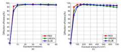
도 4의 (a)는 R, G, B 각각의 컬러에 대해 노출시간에 따른 회절효율을 나타낸 것이고, 도 4의 (b)는 R, G, B 각각의 컬러에 대해 노출 에너지에 따른 회절효율을 나타낸 것이다.FIG. 4A shows the diffraction efficiency according to the exposure time for each color of R, G and B, FIG. 4B shows the diffraction efficiency according to the exposure energy for each color of R, G, Lt; / RTI >
도 4를 참조하면, red와 green의 경우 노출 에너지가 150mJ/cm2 일 때 97%의 최대 회절효율을 나타내며, blue는 노출 에너지가 200mJ/cm2 일 때 97%의 최대 회절효율을 나타낸다. 포토폴리머에 입사하는 에너지가 증가할수록 기록 빔에 의한 회절격자의 생성이 강화되므로, 투과 빔의 세기는 점점 감소하게 되며, 회절 빔의 세기는 점점 증가한다. 모든 모노머는 폴리머로 변하며, 회절효율은 포화상태에서 더 이상 변하지 않는다. 테스트 결과로부터 포토폴리머는 세 가지 컬러에 대해 비슷한 에너지특성을 갖고 있으며, 최대 97%의 매우 높은 회절효율을 나타내고 있다. 아래의 기타 파라미터들의 특성에 대한 측정 실험에서 노출 에너지에 있어, red와 green은 150mJ/cm2, blue는 200mJ/cm2 인 조건하에서 진행하기로 한다.
Referring to FIG. 4, red and green exhibit a maximum diffraction efficiency of 97% at an exposure energy of 150 mJ / cm2 , and blue exhibits a maximum diffraction efficiency of 97% at an exposure energy of 200 mJ / cm2 . As the energy incident on the photopolymer is increased, the generation of the diffraction grating by the recording beam is strengthened, so that the intensity of the transmission beam is gradually decreased and the intensity of the diffraction beam is gradually increased. All monomers are converted to polymers, and the diffraction efficiency is no longer changing in the saturated state. From the test results, the photopolymer has similar energy characteristics for the three colors and exhibits a very high diffraction efficiency of up to 97%. For measurements of the other parameters below, we will proceed under the conditions of red and green of 150 mJ / cm2 and blue of 200 mJ / cm2 for the exposure energy.
한편, 입사각도에 따른 특성을 분석하기 위하여 물체 빔과 매질법선 사이 각도는 10° ~ 70°까지 5°간격으로 변화시켜 R, G, B 각각의 컬러에 대해 각각의 회절효율을 측정한다. 이 결과는 도 5에 도시되어 있다.In order to analyze the characteristics according to the incident angle, the angle between the object beam and the medium normal is varied from 5 ° to 10 ° from the angle of 10 ° to 70 °, and the respective diffraction efficiencies are measured for R, G and B colors. This result is shown in Fig.
도 5는 입사각도에 따른 포토폴리머의 회절효율 분포도이다.5 is a diffraction efficiency distribution diagram of a photopolymer according to an incident angle.
도 5를 참조하면, Red는 10° ~ 60° 사이에서 90% 이상의 회절효율 갖고, green은 10° ~ 60° 사이에서 90% 이상의 회절효율을 가지며, blue는 30° ~ 60° 사이에서 90% 이상의 효율을 갖는다. 즉, 두 빔의 입사각의 합이 30° ~ 60° 범위 내에서는 기록구조와 관계없이 최소 90% 이상의 회절효율을 갖는 격자의 설계가 가능함을 알 수 있다.
Referring to FIG. 5, Red has a diffraction efficiency of 90% or more at 10 ° to 60 °, green has a diffraction efficiency of 90% or more at 10 ° to 60 °, blue has a diffraction efficiency at 90% Or more. That is, it can be seen that a grating having a diffraction efficiency of at least 90% regardless of the recording structure can be designed within the range of the incidence angles of the two beams within the range of 30 ° to 60 °.
다음으로, 포토폴리머의 각도 선택성 특성을 분석한다. 각도 선택성은 Kogelnik의 2광파 결합이론에서 유도될 수 있다. Bragg 각 편차에 의한 회절효율의 이론적 시뮬레이션 값과, 실제 실험으로 측정한 값들의 분포는 도 6과 같다.Next, the angle selectivity characteristic of the photopolymer is analyzed. Angle selectivity can be derived from Kogelnik's two-wave coupled theory. The theoretical simulation values of the diffraction efficiency due to the Bragg angle deviation and the distribution of the values measured by the actual experiment are shown in FIG.
도 6은 각도 선택성에 따른 포토폴리머의 회절효율 분포도이다.6 is a diffraction efficiency distribution diagram of the photopolymer according to the angle selectivity.
도 6을 참조하면, 계산된 포토폴리머의 각도 선택성은 r, g, b 세 컬러에 대해 각각, red는 ±6.7°, green은 ±6°, blue는 ±5.4°이고, 실제 실험을 통해 획득한 측정값은 red는 ±6.6°, green은 ±6°, blue는 ±5.3°이다. 본 실험을 통해 포토폴리머는 비교적 넓은 각도 선택성을 갖고 있다는 것을 확인할 수 있다.
Referring to FIG. 6, the calculated angular selectivity of the photopolymer is ± 6.7 ° for red, ± 6 ° for red, and ± 5.4 ° for red, g and b colors, respectively. The measured values are ± 6.6 ° for red, ± 6 ° for green, and ± 5.3 ° for blue. This experiment shows that the photopolymer has relatively wide angle selectivity.
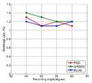
마지막으로, 반사형 비대칭 구조에서 제일 중요한 파라미터중의 하나인 수축률 특성에 대해 분석한다. 대칭구조 기록시와는 달리 비대칭 구조에서는 매질의 수축현상이 발생한다. 그러므로 실제 기록했던 입사각에서 최대회절효율이 측정되지 않고, Shift된 Bragg각에서 최대 회절효율이 측정되는 현상이 나타난다. 각도에 의한 수축률 분포는 도 7과 같다.
Finally, we analyze the shrinkage characteristics, one of the most important parameters in the reflective asymmetric structure. Unlike symmetric structure recording, contraction of medium occurs in asymmetric structure. Therefore, the maximum diffraction efficiency is not measured at the actually recorded incident angle, and the maximum diffraction efficiency is measured at the shifted Bragg angle. Shrinkage distribution by angle is shown in Fig.
도 8은 풀 컬러 HOE를 제작하기 위한 실험 셋업이다.Figure 8 is an experimental setup for making a full color HOE.
먼저, 도 8의 참조부호에 대해 설명한다.First, reference numerals of FIG. 8 will be described.
S : SplitterS: Splitter
NDF : Neutral Density FilterNDF: Neutral Density Filter
H :
M : MirrorM: Mirror
DM : Dichroic MirrorDM: Dichroic Mirror
SF : Spatial FilterSF: Spatial Filter
L : LensL: Lens
A : ApertureA: Aperture
PBS : Polarization Beam SplitterPBS: Polarization Beam Splitter
2 : 기록유닛2: recording unit
81, 82 : 검출기81, 82: Detector
83, 84 : 파워미터
83, 84: Power meter
도 8을 참조하면, 레이저에서 출력된 빔을 SF, 렌즈를 통해 평행 광으로 만들고 빔 분리기로 물체 빔과 참조 빔을 생성한다. 물체 빔과 참조 빔을 매질인 포토폴리머에 양 방향에서 조사하여 반사형 홀로그램 격자를 기록한다. 한편, 셔터를 이용하여 사용하려고 하는 레이저를 조절한다.Referring to FIG. 8, a beam output from a laser is converted into parallel light through an SF lens, and an object beam and a reference beam are generated by a beam splitter. The object beam and the reference beam are irradiated to the photopolymer as a medium in both directions to record a reflective holographic grating. On the other hand, a shutter is used to adjust the laser to be used.
여기서 주의해야 할 점은

본 발명의 풀 컬러 HOE를 제작하는 과정은, 두께 191μm의 제1포토폴리머의 일측에는 두께 20mm의 도광판(도 3의 31)과 타측에는 두께 30mm의 프리즘을 부착시키고 도광판(도 3의 31)을 통하여 제1포토폴리머에 수평방향으로 참조 빔(reference beam)을 입사시키며, 프리즘을 통하여 제1포토폴리머에 참조 빔과 40° ~ 60°(바람직하게 55°의 각도)를 이루도록 적색 레이저의 물체 빔을 입사시켜 적색(red)광용 포토폴리머를 형성시키고 강도 350μW/㎠의 자외선을 1 ~ 5분간(바람직하게 2분) 조사하는 적색광 기록 단계와, 형성된 적색광용 포토폴리머를 20 ~ 30 시간 상온에서 건조시킨 후, 건조된 적색광용 포토폴리머에 동일한 두께의 제2포토폴리머를 접착시킨 다음, 적색광용 포토폴리머 측에는 도광판(도 3의 31)을 제2포토폴리머 측에는 두께 30mm의 프리즘을 부착시킨 후 제2포토폴리머에 수평방향으로 참조 빔(reference beam)을 입사시키며, 프리즘을 통하여 제2포토폴리머에 참조 빔과 40° ~ 60°(바람직하게 55°의 각도)를 이루도록 녹색과 파랑 레이저가 합쳐진 물체 빔을 입사시켜 녹색(green) 및 파랑(blue)광용 포토폴리머를 형성시키고 강도 350μW/㎠의 자외선을 1 ~ 5분간(바람직하게 2분) 조사하는 녹색(green) 및 파랑(blue) 기록 단계를 포함한다.
In the process of manufacturing the full-color HOE of the present invention, a light guide plate (31 in FIG. 3) having a thickness of 20 mm and a prism having a thickness of 30 mm are attached to one side of a first photopolymer having a thickness of 191 m, A reference beam is incident on the first photopolymer in a horizontal direction and the reference beam is incident on the first photopolymer through the prism so as to form an angle of 40 ° to 60 ° (preferably, 55 °) with respect to the reference beam, A red light recording step of forming a red light photopolymer and irradiating ultraviolet light having an intensity of 350 μW / cm 2 for 1 to 5 minutes (preferably 2 minutes), and drying the formed photopolymer for red light for 20 to 30 hours at room temperature A second photopolymer of the same thickness is adhered to the dried red light photopolymer, a light guide plate (31 of FIG. 3) is attached to the red light photopolymer side, a prism of 30 mm thickness is attached to the second photopolymer side, A reference beam is incident horizontally on the top polymer, and an object beam, in which a green and a blue laser are combined with the second photopolymer through the prism to form a 40 ° to 60 ° (preferably 55 °) angle with the reference beam (Green) and blue (blue) recording step of irradiating ultraviolet light having an intensity of 350 μW / cm 2 for 1 to 5 minutes (preferably 2 minutes) to form green and blue photopolymers, do.
한편, 본 발명과의 비교를 위해 실험한 결과들이다.On the other hand, experimental results for comparison with the present invention are shown.
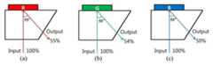
먼저, 특성 분석으로부터 최적의 기록조건으로 R, G, B 각 컬러에 대해 HOE를 기록하였으며, 이때 각 컬러에 대한 HOE의 출력 효율은 도 9와 같이 red는 55%, green은 54%, blue는 50% 이다. 이때의 효율 측정은 회절 빔 대 입사 빔의 비이다. 이는 포토폴리머의 흡수, 재생하는 과정에서 도광판(도 1의 14)에 의해 손실되는 효율을 모두 고려한 것이다.
First, from the characteristic analysis, the HOE was recorded for each color of R, G, B with optimum recording conditions. The output efficiency of the HOE for each color was 55% for red, 54% for green, 50%. The efficiency measurement at this time is the ratio of the diffracted beam to the incident beam. This is in consideration of all the efficiencies lost by the light guide plate (14 in Fig. 1) in the process of absorbing and regenerating the photopolymer.
HOE의 성능을 테스트하기 위하여 각 컬러에 대해 두 장의 HOE를 제작하여 도 10과 같이 도광판(도 1의 14)에 부착하여 제안한 HMD 시스템에 적용하여 실험을 진행하였다. 마이크로 디스플레이(도 1의 11)를 이용하여 couple in 쪽에 영상을 조사하고 couple out 쪽에는 카메라로 영상을 캡처 하였다. 그 결과 영상은 도 11에 나타난 바와 같다. 도 11의 (a)는 입력 영상이고, 도 11의 (b), (c), (d)는 각각 R, G, B 컬러에 대한 출력 영상이다.
In order to test the performance of the HOE, two HOEs were prepared for each color and attached to the light guide plate (14 in FIG. 1) as shown in FIG. 10, and the experiment was applied to the proposed HMD system. The micro display (11 in FIG. 1) was used to illuminate the image on the couple in side and the camera on the couple out side was captured with the camera. The resulting image is as shown in FIG. 11A is an input image, and FIGS. 11B, 11C and 11D are output images for R, G and B colors, respectively.
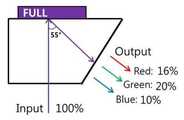
이어서, 풀 컬러 HMD를 실현하기 위하여 풀 컬러 구현 방법에 대해 설명한다. 먼저, 세 가지 컬러를 합쳐서 한 장의 포토폴리머에 HOE를 기록한다.Next, a full color implementation method will be described to realize a full color HMD. First, the three colors are combined to record the HOE in one photopolymer.
동시에 기록을 했을 때, inter modulation 현상이 일어나기 때문에 단색을 기록했을 때 보다 회절 효율이 낮게 나타난다. 레이저로 출력 효율을 측정한 결과, 도 12와 같이, red는 16%, green은 20%, blue는 10%로 나타났다. 이는 컬러의 균일도가 일치하지 않고 또한 효율도 전체적으로 매우 낮은 결과이다.
When recording is performed at the same time, the diffraction efficiency is lower than when recording a single color because inter modulation phenomenon occurs. As a result of measuring the output efficiency with a laser, red was 16%, green was 20% and blue was 10% as shown in Fig. This results in inconsistencies in color uniformity and in overall efficiency.
한편, 풀 컬러 HMD를 실현하기 위하여 회절효율이 제일 높은 순으로 차례로 적층한다. 이렇게 기록한 HOE의 출력 효율은, 도 13과 같이, red는 10%, green은 23%, blue는 30%로 나타났다. 3층으로 적층하면 제일 외곽 층에 있는 HOE에서 효율이 많이 떨어지기 때문에, 이에 적층방법을 2층으로 변경하는 것이 바람직하다.On the other hand, in order to realize the full-color HMD, the diffraction efficiency is stacked in order from the highest order. As shown in Fig. 13, the output efficiency of the recorded HOE was 10% for red, 23% for green, and 30% for blue. Since the efficiency of HOE in the outermost layer decreases considerably, it is preferable to change the lamination method to two layers.
즉, 효율이 가장 높은 red HOE와, green HOE과 blue HOE를 합한 HOE를 적층하여 기록한다. 이에 레이저를 이용하여 효율을 측정한 결과, 도 14과 같이, 출력 효율에 있어 red는 40%, green은 44%, blue는 42%로 나타났다. 이는 각 컬러마다 평균 40%의 높은 효율을 나타내기 때문에 최종 적층구조로 선택하여 HMD 시스템에 적용한 것이다.
That is, the red HOE having the highest efficiency and the HOE including the green HOE and the blue HOE are laminated and recorded. As a result of measuring the efficiency using the laser, as shown in Fig. 14, the red efficiency was 40%, the green efficiency was 44%, and the blue efficiency was 42%. This shows that the average efficiency is 40% for each color, so it is selected as the final laminated structure and applied to the HMD system.
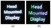
상기한 설명을 통해 제작된 풀 컬러 HOE의 성능을 테스트하기 위해, 도 15와 같이 HMD 시스템에 적용한다. 두 장의 풀 컬러 HOE를 도광판(도 1의 14)에 부착한 후, 마이크로 디스플레이(도 1의 11)를 이용하여 couple in 쪽에 영상을 조사하고 couple out 쪽에는 카메라로 영상을 캡처한다. 그 결과, 영상은 도 16에 나타난 바와 같다.In order to test the performance of the full color HOE manufactured through the above description, it is applied to the HMD system as shown in FIG. After attaching the two full-color HOEs to the light guide plate (14 in FIG. 1), the image is taken on the couple in side using the microdisplay (11 in FIG. As a result, the image is as shown in Fig.
도 16으로부터 포토폴리머를 이용하여 풀 컬러 HOE를 제작하여 HMD에 적용 가능하다는 것을 확인할 수 있다.
16, it can be confirmed that a full-color HOE is manufactured using a photopolymer and is applicable to an HMD.
상기한 본 발명을 요약하면 다음과 같다.The present invention is summarized as follows.
기존의 HMD의 광학계 중 디스플레이 소자에서 도광판 안으로 들어오는 couple in 광학계와 도광판 안에서 내부 전반사에 의해 진행하는 영상을 동공으로 입사시키는 couple out 광학계를 HOE로 구현하였다. HOE의 기록매질로는 포토폴리머를 사용하였으며, 이를 실현하기 위해서 포토폴리머의 R, G, B 각 컬러에 대한 전반적인 광학특성을 분석하였다. 그 결과 포토폴리머의 노출 에너지에 따른 특성은 red와 green 레이저에 대해 노출 에너지가 150mJ/cm2 일 때 97%의 최대회절효율을 나타내며, blue 레이저에 대해 노출 에너지가 200mJ/cm2 일 때 97%의 최대회절효율을 나타낸다. 빔이 노출이 계속되면 효율은 점차 떨어지면서 나중에는 포화상태에 도달하여 더 이상 변하지 않는다. 포토폴리머는 세 가지 컬러에 대해 비슷한 에너지특성을 갖고 있으며, 최대로 97%의 매우 높은 회절효율을 나타냈다. 기록 각도에 따른 특성은 red는 10° ~ 60° 사이에서 90% 이상의 회절효율 갖고 green은 10° ~ 60° 사이에서 90% 이상의 회절효율을 가지며 blue는 30° ~ 60° 사이에서 90% 이상의 효율을 갖는다. 각도선택성에 따른 특성은 입사각 45°일 때 red는 ±6.6°, green은 ±6°, blue는 ±5.3°이다. 본 실험을 통해 포토폴리머는 비교적 넓은 각도 선택성을 갖고 있다는 것을 확인할 수 있다. 마지막으로, 포토폴리머의 수축률은 R, G, B 각각의 컬러에 대해 약 1.2%, 1.3%, 1.2%이다. 전반적으로 포토폴리머는 R, G, B 컬러에 대해 비슷한 광학 특성을 나타낸다.Among the optical systems of the conventional HMD, a couple in optical system that enters the light guide plate in the display device and a couple out optics that enters the pupil through the total internal reflection in the light guide plate are implemented in the HOE. Photopolymer was used as the recording medium of the HOE. In order to realize this, the optical characteristics of R, G, B of the photopolymer were analyzed. As a result, picture characteristics in accordance with the exposure energy of the polymer indicates the maximum diffraction efficiency of 97% when the exposure energy is in the 150mJ / cm2 for the red and green laser, 97% when the exposure energy of 200mJ / cm2 days for blue laser Of the maximum diffraction efficiency. As the beam continues to be exposed, the efficiency gradually decreases and later it reaches saturation and does not change anymore. The photopolymer had similar energy characteristics for the three colors and showed very high diffraction efficiencies of up to 97%. The characteristic according to the recording angle is that red has a diffraction efficiency of 90% or more between 10 ° and 60 °, green has a diffraction efficiency of 90% or more between 10 ° and 60 ° and blue has a efficiency of 90% or more between 30 ° and 60 ° Respectively. The characteristics according to the angle selectivity are ± 6.6 ° for red, ± 6 ° for green, and ± 5.3 ° for blue when the incident angle is 45 °. This experiment shows that the photopolymer has relatively wide angle selectivity. Finally, the shrinkage of the photopolymer is about 1.2%, 1.3%, and 1.2% for the colors R, G, and B, respectively. Overall, photopolymers exhibit similar optical properties for R, G, and B colors.
포토폴리머의 특성분석 데이터를 바탕으로 HOE의 제작에 필요한 최적을 기록조건을 찾았고, 그 조건에서 HOE 샘플을 제작하였으며, 패턴 타깃을 사용하여 포토폴리머의 해상도를 확인하였다. 제안한 HMD에 적용에 적합하다고 판단하여 HMD에 적용할 HOE의 기록구조와 풀 컬러 구현방법을 연구하였다. 풀 컬러 구현으로는 적층방법을 선택하였으며, 추후 제작된 HOE를 제안한 HMD 시스템에 적용하여 마이크로 디스플레이로 영상을 테스트한 결과 포토폴리머를 이용하여 HMD용 풀 컬러 HOE의 제작이 가능하다는 것을 확인하였다.
Based on the characterization data of the photopolymer, the optimal recording conditions for the HOE were obtained, and the HOE sample was prepared under the conditions and the resolution of the photopolymer was confirmed using the pattern target. We have studied the recording structure and full color implementation method of the HOE to be applied to the HMD. As a full color implementation, we selected a stacking method. We applied the developed HOE to the proposed HMD system and tested the image with a microdisplay. As a result, we confirmed that it is possible to fabricate a full color HOE for HMD using photopolymer.
이상에서 몇 가지 실시예를 들어 본 발명을 더욱 상세하게 설명하였으나, 본 발명은 반드시 이러한 실시예로 국한되는 것이 아니고 본 발명의 기술사상을 벗어나지 않는 범위 내에서 다양하게 변형실시될 수 있다.
While the present invention has been particularly shown and described with reference to exemplary embodiments thereof, it is to be understood that the invention is not limited to the disclosed exemplary embodiments, but, on the contrary, is intended to cover various modifications and equivalent arrangements included within the spirit and scope of the invention.
11 : 마이크로 디스플레이
12 : 시준 렌즈
13 : 커플 인 광학계(Couple in Optics)
14 : 도광판(Light Guide Plate)
15 : 커플 아웃 광학계(Couple out Optics)11: Microdisplay
12: Collimating lens
13: Couple in Optics
14: Light guide plate
15: Couple out optics
Claims (11)
Translated fromKorean상기 적색광용 포토폴리머에 대해, 적색 기록을 위한 자외선을 조사하는 단계;
상기 적색광용 포토폴리머를 건조시키는 단계;
상기 적색광용 포토폴리머에 제2포토폴리머를 접착시키는 단계;
상기 적색광용 포토폴리머에 도광판을 부착시키고, 상기 제2포토폴리머에 프리즘을 부착시키는 단계;
상기 적색광용 포토폴리머에 부착된 도광판으로 참조 빔을 입사시키고, 상기 제2포토폴리머에 부착된 프리즘으로 상기 참조 빔과 40° ~ 60° 범위내에서 녹색 및 청색이 결합된 레이저의 물체 빔을 입사시켜 녹색 및 청색광용 포토폴리머를 형성시키는 단계; 및
상기 녹색 및 청색광용 포토폴리머에 대해, 녹색 및 청색 기록을 위한 자외선을 조사하는 단계를 포함하는 포토폴리머를 이용한 풀 컬러 홀로그래픽 광학소자의 제조방법.
A reference beam is incident on a light guide plate formed on one side of the first photopolymer and an object beam of red laser is incident on the prism formed on the other side of the first photopolymer in a range of 40 ° to 60 ° with respect to the reference beam, Forming a polymer;
Irradiating the photopolymer for red light with ultraviolet light for red recording;
Drying the red light photopolymer;
Bonding the second photopolymer to the red light photopolymer;
Attaching a light guide plate to the red light photopolymer and attaching a prism to the second photopolymer;
A reference beam is incident on a light guide plate attached to the red light photopolymer and an object beam of a laser, in which green and blue light are combined with the reference beam in a range of 40 ° to 60 ° with a prism attached to the second photopolymer, Thereby forming a photopolymer for green and blue light; And
And irradiating the photopolymer for green and blue light with ultraviolet light for green and blue recording. 2. A method for manufacturing a full-color holographic optical element using a photopolymer, comprising:
A full color holographic optical element using a photopolymer produced by the method of claim 1.
상기 디스플레이를 시준하는 시준 렌즈;
상기 시준 렌즈를 통과한 광을 회절시키는 청구항 1의 방법으로 제조된 포토폴리머를 이용한 풀 컬러 홀로그래픽 광학소자를 갖는 커플 인 광학계(Couple in Optics);
회절된 광을 전반사시켜 유도하는 도광판(Light Guide Plate); 및
상기 도광판을 통해 유도된 회절된 광을 출력시키는 청구항 1의 방법으로 제조된 포토폴리머를 이용한 풀 컬러 홀로그래픽 광학소자를 갖는 커플 아웃 광학계(Couple out Optics)를 포함하는 포토폴리머를 이용한 풀 컬러 홀로그래픽 광학소자를 갖는 표시장치.
A display for outputting a source image;
A collimating lens for collimating the display;
An optical system (Couple in Optics) which is a couple having a full-color holographic optical element using the photopolymer produced by the method of claim 1 which diffracts light passing through the collimating lens;
A light guide plate for guiding the diffracted light by total reflection; And
Color holographic optical system using a photopolymer including a coupling-out optical system (Couple-out Optics) having a full-color holographic optical element using the photopolymer manufactured by the method of claim 1 for outputting diffracted light derived through the light guide plate A display device having an optical element.
상기 포토폴리머를 이용한 풀 컬러 홀로그래픽 광학소자를 갖는 표시장치는 안경형 표시장치인 포토폴리머를 이용한 풀 컬러 홀로그래픽 광학소자를 갖는 표시장치.11. The method of claim 10,
A display device having a full-color holographic optical element using the photopolymer has a full-color holographic optical element using a photopolymer that is a spectral display device.
Priority Applications (1)
| Application Number | Priority Date | Filing Date | Title |
|---|---|---|---|
| KR20130056251AKR101496408B1 (en) | 2013-05-20 | 2013-05-20 | Full color holographic optical element and method for fabricating the same using photopolymer, waveguide-type head mounted display |
Applications Claiming Priority (1)
| Application Number | Priority Date | Filing Date | Title |
|---|---|---|---|
| KR20130056251AKR101496408B1 (en) | 2013-05-20 | 2013-05-20 | Full color holographic optical element and method for fabricating the same using photopolymer, waveguide-type head mounted display |
Publications (2)
| Publication Number | Publication Date |
|---|---|
| KR20140136145A KR20140136145A (en) | 2014-11-28 |
| KR101496408B1true KR101496408B1 (en) | 2015-02-27 |
Family
ID=52456478
Family Applications (1)
| Application Number | Title | Priority Date | Filing Date |
|---|---|---|---|
| KR20130056251AExpired - Fee RelatedKR101496408B1 (en) | 2013-05-20 | 2013-05-20 | Full color holographic optical element and method for fabricating the same using photopolymer, waveguide-type head mounted display |
Country Status (1)
| Country | Link |
|---|---|
| KR (1) | KR101496408B1 (en) |
Cited By (2)
| Publication number | Priority date | Publication date | Assignee | Title |
|---|---|---|---|---|
| WO2019176438A1 (en)* | 2018-03-13 | 2019-09-19 | ソニー株式会社 | Optical device, image display device, and display apparatus |
| KR20200049308A (en)* | 2018-10-31 | 2020-05-08 | 주식회사 엘지화학 | System and method for evaluating quality of diffractive light guide |
Families Citing this family (8)
| Publication number | Priority date | Publication date | Assignee | Title |
|---|---|---|---|---|
| CN104656259B (en)* | 2015-02-05 | 2017-04-05 | 上海理湃光晶技术有限公司 | The conjugation arrowband three primary colours nearly optics of the eye display device of volume holographic grating waveguide staggeredly |
| KR101893590B1 (en) | 2017-04-26 | 2018-08-31 | 인하대학교 산학협력단 | See-through type super multiview three-dimensional head mounted display apparatus using holographic optical element and display method using the same |
| KR20190097939A (en) | 2018-02-13 | 2019-08-21 | 인하대학교 산학협력단 | Hybrid holographic display device and display method using the same |
| KR102087304B1 (en) | 2018-02-22 | 2020-03-10 | 인하대학교 산학협력단 | Transmissive head-mounted maxwellian display method using photopolymer and wave guide |
| JP7358846B2 (en)* | 2019-08-28 | 2023-10-11 | セイコーエプソン株式会社 | Optical element manufacturing method, optical element and display device |
| KR102811858B1 (en)* | 2019-09-05 | 2025-05-22 | 엘지디스플레이 주식회사 | Head Mounted Display, HMD |
| US20230251487A1 (en)* | 2020-06-23 | 2023-08-10 | Lg Electronics Inc. | Spectacle-type terminal device having compact structure and method of providing image thereof |
| JP7594238B2 (en)* | 2020-12-21 | 2024-12-04 | 日本電気硝子株式会社 | Light guide plate |
Citations (4)
| Publication number | Priority date | Publication date | Assignee | Title |
|---|---|---|---|---|
| JP3907015B2 (en)* | 1996-07-08 | 2007-04-18 | 大日本印刷株式会社 | Hologram color filter and manufacturing method thereof |
| JP4382224B2 (en)* | 1999-12-06 | 2009-12-09 | 大日本印刷株式会社 | Hologram master and method for producing the same |
| JP2011002778A (en)* | 2009-06-22 | 2011-01-06 | Hoya Corp | Video display and head-mounted display |
| US8233204B1 (en) | 2009-09-30 | 2012-07-31 | Rockwell Collins, Inc. | Optical displays |
- 2013
- 2013-05-20KRKR20130056251Apatent/KR101496408B1/ennot_activeExpired - Fee Related
Patent Citations (4)
| Publication number | Priority date | Publication date | Assignee | Title |
|---|---|---|---|---|
| JP3907015B2 (en)* | 1996-07-08 | 2007-04-18 | 大日本印刷株式会社 | Hologram color filter and manufacturing method thereof |
| JP4382224B2 (en)* | 1999-12-06 | 2009-12-09 | 大日本印刷株式会社 | Hologram master and method for producing the same |
| JP2011002778A (en)* | 2009-06-22 | 2011-01-06 | Hoya Corp | Video display and head-mounted display |
| US8233204B1 (en) | 2009-09-30 | 2012-07-31 | Rockwell Collins, Inc. | Optical displays |
Cited By (6)
| Publication number | Priority date | Publication date | Assignee | Title |
|---|---|---|---|---|
| WO2019176438A1 (en)* | 2018-03-13 | 2019-09-19 | ソニー株式会社 | Optical device, image display device, and display apparatus |
| JPWO2019176438A1 (en)* | 2018-03-13 | 2021-03-11 | ソニー株式会社 | Optical device, image display device and display device |
| US11520148B2 (en) | 2018-03-13 | 2022-12-06 | Sony Corporation | Optical device, image display device, and display apparatus |
| JP7268674B2 (en) | 2018-03-13 | 2023-05-08 | ソニーグループ株式会社 | Optical device, image display device and display device |
| KR20200049308A (en)* | 2018-10-31 | 2020-05-08 | 주식회사 엘지화학 | System and method for evaluating quality of diffractive light guide |
| KR102231107B1 (en) | 2018-10-31 | 2021-03-23 | 주식회사 엘지화학 | System and method for evaluating quality of diffractive light guide |
Also Published As
| Publication number | Publication date |
|---|---|
| KR20140136145A (en) | 2014-11-28 |
Similar Documents
| Publication | Publication Date | Title |
|---|---|---|
| KR101496408B1 (en) | Full color holographic optical element and method for fabricating the same using photopolymer, waveguide-type head mounted display | |
| Piao et al. | Full color holographic optical element fabrication for waveguide-type head mounted display using photopolymer | |
| US20220137404A1 (en) | Methods and systems for generating virtual content display with a virtual or augmented reality apparatus | |
| JP2025123252A (en) | Method for fabricating optical waveguides | |
| US10859833B2 (en) | Waveguide image combiner for augmented reality displays | |
| KR102795699B1 (en) | Variable-focus virtual image devices based on polarization conversion | |
| US11474347B2 (en) | Waveguide and devices for data reflection | |
| JP2022091982A (en) | Waveguide with uniform output illumination | |
| JP6234208B2 (en) | NED polarization system for wavelength passage | |
| US8885997B2 (en) | NED polarization system for wavelength pass-through | |
| KR20150079800A (en) | Illumination device | |
| JP2010139524A (en) | Hologram recording film and method of manufacturing same, and image display apparatus | |
| KR102162994B1 (en) | Ned polarization system for wavelength pass-through | |
| CN104614869A (en) | Ternary exposure technology-based achromatic system and implementation method thereof | |
| Wu et al. | Time-scheduled exposure method for full-color high diffraction efficiency and uniformity of a photopolymer | |
| JP2023134587A (en) | parallel plate waveguide | |
| KR101598394B1 (en) | Full color holographic optical element and method for fabricating the same using photopolymer, waveguide-type head mounted display | |
| Piao et al. | Holographic optical element for head-mounted display application using photopolymer | |
| Roberts et al. | Optimization of diffractive waveplate optics for visual perception | |
| Wu et al. | Full-color reflection hologram with optimized diffraction efficiency in a one-layer photopolymer | |
| CN118519272A (en) | Near-to-eye display device | |
| GB2606573A (en) | Waveguide | |
| WO2022256444A1 (en) | Method of making holograms using liquid crystal masters | |
| JP5482932B2 (en) | Hologram recording film, method for producing the same, and image display device | |
| HK1197457A (en) | Ned polarization system for wavelength pass-through |
Legal Events
| Date | Code | Title | Description |
|---|---|---|---|
| PA0109 | Patent application | St.27 status event code:A-0-1-A10-A12-nap-PA0109 | |
| PA0201 | Request for examination | St.27 status event code:A-1-2-D10-D11-exm-PA0201 | |
| R17-X000 | Change to representative recorded | St.27 status event code:A-3-3-R10-R17-oth-X000 | |
| D13-X000 | Search requested | St.27 status event code:A-1-2-D10-D13-srh-X000 | |
| D14-X000 | Search report completed | St.27 status event code:A-1-2-D10-D14-srh-X000 | |
| R17-X000 | Change to representative recorded | St.27 status event code:A-3-3-R10-R17-oth-X000 | |
| PE0902 | Notice of grounds for rejection | St.27 status event code:A-1-2-D10-D21-exm-PE0902 | |
| E13-X000 | Pre-grant limitation requested | St.27 status event code:A-2-3-E10-E13-lim-X000 | |
| P11-X000 | Amendment of application requested | St.27 status event code:A-2-2-P10-P11-nap-X000 | |
| P13-X000 | Application amended | St.27 status event code:A-2-2-P10-P13-nap-X000 | |
| R18-X000 | Changes to party contact information recorded | St.27 status event code:A-3-3-R10-R18-oth-X000 | |
| PG1501 | Laying open of application | St.27 status event code:A-1-1-Q10-Q12-nap-PG1501 | |
| E90F | Notification of reason for final refusal | ||
| PE0902 | Notice of grounds for rejection | St.27 status event code:A-1-2-D10-D21-exm-PE0902 | |
| P11-X000 | Amendment of application requested | St.27 status event code:A-2-2-P10-P11-nap-X000 | |
| P13-X000 | Application amended | St.27 status event code:A-2-2-P10-P13-nap-X000 | |
| E701 | Decision to grant or registration of patent right | ||
| PE0701 | Decision of registration | St.27 status event code:A-1-2-D10-D22-exm-PE0701 | |
| GRNT | Written decision to grant | ||
| PR0701 | Registration of establishment | St.27 status event code:A-2-4-F10-F11-exm-PR0701 | |
| PR1002 | Payment of registration fee | St.27 status event code:A-2-2-U10-U11-oth-PR1002 Fee payment year number:1 | |
| PG1601 | Publication of registration | St.27 status event code:A-4-4-Q10-Q13-nap-PG1601 | |
| R18-X000 | Changes to party contact information recorded | St.27 status event code:A-5-5-R10-R18-oth-X000 | |
| P22-X000 | Classification modified | St.27 status event code:A-4-4-P10-P22-nap-X000 | |
| FPAY | Annual fee payment | Payment date:20180205 Year of fee payment:4 | |
| PR1001 | Payment of annual fee | St.27 status event code:A-4-4-U10-U11-oth-PR1001 Fee payment year number:4 | |
| R18-X000 | Changes to party contact information recorded | St.27 status event code:A-5-5-R10-R18-oth-X000 | |
| PR1001 | Payment of annual fee | St.27 status event code:A-4-4-U10-U11-oth-PR1001 Fee payment year number:5 | |
| FPAY | Annual fee payment | Payment date:20200204 Year of fee payment:6 | |
| PR1001 | Payment of annual fee | St.27 status event code:A-4-4-U10-U11-oth-PR1001 Fee payment year number:6 | |
| PN2301 | Change of applicant | St.27 status event code:A-5-5-R10-R13-asn-PN2301 St.27 status event code:A-5-5-R10-R11-asn-PN2301 | |
| PR1001 | Payment of annual fee | St.27 status event code:A-4-4-U10-U11-oth-PR1001 Fee payment year number:7 | |
| R18-X000 | Changes to party contact information recorded | St.27 status event code:A-5-5-R10-R18-oth-X000 | |
| PR1001 | Payment of annual fee | St.27 status event code:A-4-4-U10-U11-oth-PR1001 Fee payment year number:8 | |
| PC1903 | Unpaid annual fee | St.27 status event code:A-4-4-U10-U13-oth-PC1903 Not in force date:20230218 Payment event data comment text:Termination Category : DEFAULT_OF_REGISTRATION_FEE | |
| R18-X000 | Changes to party contact information recorded | St.27 status event code:A-5-5-R10-R18-oth-X000 | |
| PC1903 | Unpaid annual fee | St.27 status event code:N-4-6-H10-H13-oth-PC1903 Ip right cessation event data comment text:Termination Category : DEFAULT_OF_REGISTRATION_FEE Not in force date:20230218 |