KR101495639B1 - Medical matrix and medical bed using the same - Google Patents
Medical matrix and medical bed using the sameDownload PDFInfo
- Publication number
- KR101495639B1 KR101495639B1KR20140152391AKR20140152391AKR101495639B1KR 101495639 B1KR101495639 B1KR 101495639B1KR 20140152391 AKR20140152391 AKR 20140152391AKR 20140152391 AKR20140152391 AKR 20140152391AKR 101495639 B1KR101495639 B1KR 101495639B1
- Authority
- KR
- South Korea
- Prior art keywords
- air
- matrix
- flexible tube
- filter
- medical
- Prior art date
- Legal status (The legal status is an assumption and is not a legal conclusion. Google has not performed a legal analysis and makes no representation as to the accuracy of the status listed.)
- Expired - Fee Related
Links
Images


Classifications
- A—HUMAN NECESSITIES
- A61—MEDICAL OR VETERINARY SCIENCE; HYGIENE
- A61G—TRANSPORT, PERSONAL CONVEYANCES, OR ACCOMMODATION SPECIALLY ADAPTED FOR PATIENTS OR DISABLED PERSONS; OPERATING TABLES OR CHAIRS; CHAIRS FOR DENTISTRY; FUNERAL DEVICES
- A61G7/00—Beds specially adapted for nursing; Devices for lifting patients or disabled persons
- A61G7/05—Parts, details or accessories of beds
- A—HUMAN NECESSITIES
- A47—FURNITURE; DOMESTIC ARTICLES OR APPLIANCES; COFFEE MILLS; SPICE MILLS; SUCTION CLEANERS IN GENERAL
- A47C—CHAIRS; SOFAS; BEDS
- A47C21/00—Attachments for beds, e.g. sheet holders or bed-cover holders; Ventilating, cooling or heating means in connection with bedsteads or mattresses
- A47C21/04—Devices for ventilating, cooling or heating
- A47C21/048—Devices for ventilating, cooling or heating for heating
- A—HUMAN NECESSITIES
- A47—FURNITURE; DOMESTIC ARTICLES OR APPLIANCES; COFFEE MILLS; SPICE MILLS; SUCTION CLEANERS IN GENERAL
- A47C—CHAIRS; SOFAS; BEDS
- A47C27/00—Spring, stuffed or fluid mattresses or cushions specially adapted for chairs, beds or sofas
- A47C27/08—Fluid mattresses
- A47C27/081—Fluid mattresses of pneumatic type
- A—HUMAN NECESSITIES
- A61—MEDICAL OR VETERINARY SCIENCE; HYGIENE
- A61G—TRANSPORT, PERSONAL CONVEYANCES, OR ACCOMMODATION SPECIALLY ADAPTED FOR PATIENTS OR DISABLED PERSONS; OPERATING TABLES OR CHAIRS; CHAIRS FOR DENTISTRY; FUNERAL DEVICES
- A61G7/00—Beds specially adapted for nursing; Devices for lifting patients or disabled persons
- A61G7/002—Beds specially adapted for nursing; Devices for lifting patients or disabled persons having adjustable mattress frame
- A61G7/015—Beds specially adapted for nursing; Devices for lifting patients or disabled persons having adjustable mattress frame divided into different adjustable sections, e.g. for Gatch position
Landscapes
- Health & Medical Sciences (AREA)
- Nursing (AREA)
- Life Sciences & Earth Sciences (AREA)
- Animal Behavior & Ethology (AREA)
- General Health & Medical Sciences (AREA)
- Public Health (AREA)
- Veterinary Medicine (AREA)
- Accommodation For Nursing Or Treatment Tables (AREA)
Abstract
Description
Translated fromKorean본 발명은 의료용 매트릭스 및 이를 이용한 의료용 침대에 관한 것으로서, 특히 가열 또는 냉각된 에어를 고 신축성 튜브를 이용하여 통기성 매트릭스에 주입하여 환자를 간접 가열(또는 냉각) 함으로써 중환자나 임종을 앞둔 환자의 오열과 고통을 최소화하는 의료용 매트릭스 및 이를 이용한 의료용 침대에 관한 것이다.The present invention relates to a medical matrix and a medical bed using the medical matrix. More particularly, the present invention relates to a medical matrix and a medical bed using the medical matrix. More particularly, the present invention relates to a medical matrix and a medical bed using the matrix, The present invention relates to a medical matrix for minimizing pain and a medical bed using the same.
현재 널리 이용되는 의료용 침대나 의료용 매트릭스는 3단으로 접히는 다단 매트릭스, 및 다단 매트릭스를 수납하며, 환자가 누웠을 때, 머리나 다리를 받치는 부분의 각도를 꺽는 구조를 갖는다. 이는 환자가 의료용 침대에 누워 있을 때, 다리를 올리거나, 머리를 올리거나 또는 수면을 취하는 다양한 자세에 대응할 수 있도록 하는데 따른다. 이에 더하여, 보다 나은 조작성을 위해, 전동으로 의료용 침대의 각도를 조절하는 전동형 의료용 침대가 개시된 바 있으며, 의료용 침대에서 환자가 따듯하게 지낼 수 있도록 하기 위해 의료용 침대 내부에 전열선을 매립하고, 매립된 전열선에 전기를 가하여 의료용 침대를 가열하는 기술(공개특허 특2001-0078665호)도 제안된 바 있다.Currently widely used medical beds and medical matrices contain a multi-stage matrix, which is folded into three stages, and a multi-stage matrix, and have a structure that breaks the angle of the head or leg supporting part when the patient is lying down. This is followed by allowing the patient to respond to various postures, such as lifting the legs, raising the head, or taking a sleep when lying on a medical bed. In addition, for the sake of better operability, a motorized medical bed for regulating the angle of the medical bed with electric power has been disclosed. In order to allow the patient to stay warm in the medical bed, the heating wire is embedded in the medical bed, A technique for heating the medical bed by applying electricity to the heating wire (Patent Laid-Open No. 2001-0078665) has also been proposed.
공개특허 특2001-0078665는 1자 형의 침대에 열선을 매립하고 매립된 열선에 전기를 가하여 침대를 가열하는 직접적인 가열 방식을 이용하고 있다. 전열선을 이용하는 직접 가열 방식은 전열선이 유발하는 전자파가 정상인에게도 유익하지 못하며, 전열선이 매립된 매트는 3단 또는 그 이상으로 접히는 의료용 침대에서의 내구성이 우수할 수 없다.Japanese Patent Application Laid-Open No. 2001-0078665 uses a direct heating method in which a heating wire is embedded in a one-shaped bed and electricity is applied to the embedded heating wire to heat the bed. In the direct heating method using the heating wire, the electromagnetic wave induced by the heating wire is not beneficial to the normal person, and the mat in which the heating wire is embedded can not have excellent durability in the medical bed folded into three or more stages.
본 발명의 목적은 가열된 공기가 의료용 매트 내부에서 환자를 향해훈기되도록간접 가열하며,An object of the present invention istoindirectly heat the heated air to be sucked toward the patient inside the medical mat,
환자가 매트에 누워있는 상태일 때 환자의 훈기를 위한배관이 환자에게 이물감을 주지 않도록하고,So that the patient isnot a discomfort to the patient tubing for patients hungi when the state lying on the mat,and
의료용 매트가 접히거나 펼쳐질 때에도 내구성이 보장되는 의료용 매트 및 이를 이용한 의료용 침대를 제공함에 있다. 또한, 본 발명의 다른 목적은 의료용 매트에서 훈기되는 공기(Air)의 산소 함유량을 증가시켜 환자의 건강 회복을 증진시킴은 물론, 필요에 따라서 에어의 온도가 증감되도록 하는 의료용 매트 및 이를 이용한 의료용 침대를 제공함에 있다.A medical mat having durability even when the medical mat is folded or unfolded, and a medical bed using the same. Another object of the present invention is to provide a medical mat which increases the oxygen content of the air to be aired in the medical mat to thereby improve the health recovery of the patient, .
상기한 목적은 본 발명에 따라, 침대 프레임에 거치되는 공기 투과형의 매트릭스 및 매트릭스 내부에 매립되며, 환자와의 접촉 면을 향해 적어도 하나의 공기 방출구가 형성되고, 일 측 종단은 매트릭스 외부로 노출되어 공기 흡입구를 형성하는 플렉서블 튜브를 포함하며, 플렉서블 튜브는, 공기 흡입구로 유입된 공기를 공기 방출구로 토출하고, 매트릭스는, 공기 방출구를 통해 토출된 공기를 접촉 면으로 간접 유도하며, 공기 흡입구는, 매트릭스 외부로 노출된 영역의 외주연은 매트릭스의 표면을 따라 연장되어 테두리를 형성하고, 테두리에서 중심부 방향으로 비탈면을 이루며 돌출되어 돌출 캡을 형성하는 의료용 매트릭스에 의해 달성된다.According to the present invention, there is provided an air-permeable matrix embedded in a bed frame and embedded in the matrix, wherein at least one air outlet is formed toward the contact surface with the patient, and one side end is exposed to the outside of the matrix And the flexible tube discharges the air introduced into the air inlet port to the air outlet port, the matrix indirectly guides the air discharged through the air outlet port to the contact surface, and the air inlet port Is achieved by a medical matrix in which the outer periphery of the region exposed to the outside of the matrix extends along the surface of the matrix to form a rim and protrudes to form a sloped surface in the direction from the rim to the central portion to form the protruding cap.
상기한 목적은 본 발명에 따라, 일 영역에 공기 토출구가 형성되는 침대 프레임, 침대 프레임에 거치되는 공기 투과형의 매트릭스, 매트릭스 내부에 매립되며, 환자와의 접촉면을 향해 적어도 하나의 공기 방출구가 형성되고, 일 측 종단은 매트릭스 외부로 노출되어 공기 흡입구를 형성하는 플렉서블 튜브, 침대 프레임의 배면에 배치되며, 냉기 또는 열기를 생성하여 플렉서블 튜브로 전달하는 공기 조화기를 포함하며, 공기 조화기는, 에어 필터 또는 멤브레인 산소필터와 연결되어 필터링 된 공기를 플렉서블 튜브로 전달하는 의료용 매트릭스를 구비하는 의료용 침대에 의해 달성된다.According to an aspect of the present invention, there is provided an air-permeable matrix in which a bed frame having an air outlet formed in one area, an air-permeable matrix placed in a bed frame, at least one air outlet formed toward the contact surface with the patient The air conditioner includes a flexible tube which is exposed to the outside of the matrix to form an air intake port, an air conditioner disposed on the back surface of the bed frame and generating cold air or heat to transmit the air to the flexible tube, Or a medical matrix connected to the membrane oxygen filter to deliver the filtered air to the flexible tube.
본 발명에 따른 의료용 매트릭스 및 이를 이용한 의료용 침대는,The medical matrix according to the present invention and the medical bed using the same,
- 의료용 매트 내부에서 환자를 향해 훈기되도록 간접 가열하므로 전열선을 이용하는 직접 가열방식과는 달리 환자의 건강에 부정적인 영향을 끼치지 않고,- It indirectly heats the inside of the medical mat so as to be exposed to the patient. Therefore, unlike the direct heating method using the heating wire, it does not adversely affect the health of the patient,
- 환자가 침대에 누워있을 때, 훈기를 위한 배관구조가 환자에게 이물감이 가지 않도록 하고,- When the patient is lying on the bed, the piping structure for the ventilation prevents the patient from feeling foreign body,
- 훈기되는 에어(Air)는 외부의 오염물질과 세균이 필터링되고, 산소 함유량이 증대되도록 하여 환자의 회복을 증진시키고, 오한을 감소시키고,- The air that is being aired filters the foreign contaminants and bacteria, increases the oxygen content, improves the recovery of the patient, reduces the chills,
- 펠티어 소자를 이용하여 환자가 요구하는 온도로 훈기 함으로써 전열선을 이용하는 방식과는 달리 온기나 냉기를 선택적으로 제공하며,- Unlike the method of using the Peltier device to heat the patient to the required temperature,
- 에어 필터와 멤브레인 산소 필터는 카트리지 교체식으로 구성하여 유지 보수가 용이하다.- The air filter and membrane oxygen filter are easy to maintain by replacing the cartridge.
도 1은 본 발명의 일 실시예에 따른 의료용 침대의 사시도를 도시한다.
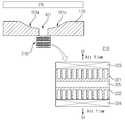
도 2는 도 1에 도시된 의료용 매트릭스의 훈기 구조에 대한 개념도를 도시한다.
도 3은 플렉서블 튜브의 접힘 구조를 설명하기 위한 참조도면을 도시한다.
도 4는 실시예에 따른 의료용 침대에 설치되는 공기 조화기의 일 실시예에 따른 단면 구조를 도시한다.
도 5는 실시예에 따른 매트릭스의 플렉서블 튜브와 공기 토출구의 연결방식을 설명하기 위한 참조도면을 도시한다.
도 6은 실시예에 따른 공기 조화기의 일 실시예에 따른 결합 개념도를 도시한다.
도 7은 실시예에 따른 공기 조화기의 배치 구조 및 필터 교환 방법에 대한 참조도면을 도시한다.
도 8은 실시예에 따른 공기 조화기의 공기 흐름에 대한 개념도를 도시한다.
도 9는 멤브레인 필터와 에어 필터의 적층 구조에 대한 참조도면을 도시한다.
도 10은 본 발명의 다른 실시예에 따른 공기 조화기의 일 예에 따른 사시도를 도시한다.1 shows a perspective view of a medical bed according to an embodiment of the present invention.
Fig. 2 shows a conceptual diagram of the rescue structure of the medical matrix shown in Fig.
Fig. 3 shows a reference drawing for explaining the folding structure of the flexible tube.
FIG. 4 illustrates a cross-sectional structure of an air conditioner installed in a medical bed according to an embodiment of the present invention.
5 is a view for explaining a connection method of a flexible tube and an air outlet of a matrix according to an embodiment.
6 is a conceptual diagram illustrating a coupling according to an embodiment of the air conditioner according to the embodiment.
FIG. 7 shows a reference structure of an arrangement of an air conditioner and a method of exchanging a filter according to an embodiment.
Fig. 8 shows a conceptual diagram of the airflow of the air conditioner according to the embodiment.
9 shows a reference diagram of a laminated structure of a membrane filter and an air filter.
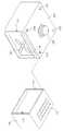
10 is a perspective view of an air conditioner according to another embodiment of the present invention.
이하, 도면을 참조하여 본 발명을 상세히 설명하도록 한다.Hereinafter, the present invention will be described in detail with reference to the drawings.
도 1은 본 발명의 일 실시예에 따른 의료용 침대의 사시도를 도시하고, 도 2는 도 1에 도시된 의료용 매트릭스의 훈기 구조에 대한 개념도를 도시하고, 도 3은 플렉서블 튜브의 접힘 구조를 설명하기 위한 참조도면을 도시한다.FIG. 1 is a perspective view of a medical bed according to an embodiment of the present invention, FIG. 2 is a conceptual diagram of a medical structure of the medical matrix shown in FIG. 1, and FIG. 3 is a view for explaining a folding structure of a flexible tube ≪ / RTI >
도 1 내지 도 3을 함께 참조하여 설명하면, 실시예에 따른 의료용 매트릭스(20)는 3단 매트릭스로서, 환자가 정 위치로 누웠을 때, 상체, 몸체, 하체에 각각 대응하는 매트(21, 22, 23)가 연결된 구조를 갖는다. 매트(21, 23)는 환자가 머리나 다리를 상 방향 또는 하 방향을 향할 수 있도록 접이식 구조를 이룰 수 있으며, 이를 위해, 침대 프레임(210)에 마련되는 레버(102)를 작동하여 매트(21, 23)에 대응하는 위치를 들어 올리거나 낮출 수 있다.1 to 3 together, the
실시예에 따른 의료용 침대는 수동식을 예시하므로 레버(102)가 장착된 것을 예시하고 있으나, 의료용 침대가 전동식인 경우, 레버(102) 대신 별도의 조작 패널이나 리모콘을 이용하여 매트(21, 23)을 구동할 수도 있다.However, in the case where the medical bed is of the electric type, the
침대 프레임(210)의 중심부에는 공기 토출구(101)가 마련되고, 침대 프레임(100)의 배면에는 공기 조화기(210)가 마련되며, 공기 조화기(210)는 공기 토출구(101)로 가열된 공기 또는 냉각된 공기를 토출할 수 있다.An
의료용 매트릭스(20)는 공기 투과형의 매트릭스로서, 내부에 미세한 기공이 다수 형성되고, 형성된 기공을 통해 공기가 유동할 수 있다. 이를 위해, 의료용 매트릭스(20)는 기공이 형성되는 천연/화학 내부 충진재(예컨대, 라텍스, 우레탄, TPE, 솜, 양털 등)와 외부 커버로 형성될 수 있으며, 외부 커버에는 다수의 홀이 형성되어 내부 충진재의 통기성을 유지할 수 있도록 한다. 외부 커버에 형성되는 홀의 지름은 0.1mm 내지 수 mm에 이를 수 있으며, 홀의 지름은 내부 충진재의 통기성에 따라 그 크기가 차별될 수 있다. 다만 한정하지는 않는다.The
의료용 매트릭스(20)의 내부에는 플렉서블 튜브(24)가 매립될 수 있다. 플렉서블 튜브(24)는 탄성과 복원력이 우수한 라텍스 재질로 형성되고, 내부는 비어있는 파이프 구조로 형성된다.A
플렉서블 튜브(24)는 매트릭스(20) 내부의 충진재 속에 매립되므로 환자의 하중이 분산되어 매트릭스(20)에 환자가 누워있는다 하더라도 튜브 내부가 잘 막히지 않는다. 플렉서블 튜브(24)는 도 3a에 도시된 바와 같이 매트릭스(20)의 중심부에 매립되거나 또는 중심부에서 매트릭스(20)의 노출면 방향으로 편향되어 배치될 수도 있다.Since the
플렉서블 튜브(24)는 고탄성이고 복원성이 우수한 라텍스 재질 또는 우레탄 재질로 형성될 수 있다. 바람직하게는 플렉서블 튜브(24)는 라텍스 재질로 형성되며, 환자가 매트릭스(20)에 누울 때, 연질의 탄성체인 플렉서블 튜브(24)는 환자의 하중이 가해지는 만큼 납작하게 수축되므로 환자는 매트릭스(20)에 누울 때 이물감을 느끼지 않을 수 있다. 만일, 플렉서블 튜브(24) 대신 경질의 합성수지나 플라스틱 파이프가 매트릭스(20) 내부에 수납된다면 환자는 매트릭스(20) 내부에 수납된 경질의 합성수지 또는 플라스틱 파이프의 존재, 즉 이물감을 느낄 수 있다. 반면, 실시예에 따른 플렉서블 튜브(24)는 환자가 매트릭스(20) 위에 누울 때, 매트릭스(20)에 가해지는 압력에 따라 일정 수준 수축되므로 이러한 이질감을 느끼지 않도록 할 수 있다.The
플렉서블 튜브(24)는 매트릭스(20) 내에 하나, 둘 또는 셋 이상이 분기되어 매립될 수 있다. 또한, 플렉서블 튜브(24)는 매트릭스(20)와 환자가 접촉하는 매트릭스(20)의 접촉면 방향으로 복수의 공기 방출구(26a, 27a)를 구비할 수 있다. 공기 방출구(26a, 27a)는 플렉서블 튜브(24)를 통해 유입되는 공기를 접촉면 방향으로 토출하고, 매트릭스(20)에 마련되는 다수의 기공을 지나 환자에게 온기를 전달할 수 있도록 한다. 플렉서블 튜브(24)에서 공기 방출구(26a, 27a)를 통해 토출되는 공기가 매트릭스(20)에 마련되는 기공을 지날 때, 기공 구조에 의해 토출되는 공기의 속도는 저하된다. 기공이 복잡한 구조인 경우 공기의 토출 속도는 더욱 낮아지고, 반대의 경우 공기의 토출 속도는 증가할 수 있다. 어느 경우에 해당하든, 기공은 매트릭스(20) 내부의 내부 충진재에 형성되고, 내부 충진재에 형성되는 기공은 공기 저항성을 가지므로 플렉서블 튜브(24)에서 토출되는 공기는 기공을 지나면서 토출 속도가 낮아진다.One, two, or three or more of the
이에 따라, 플렉서블 튜브(24)에서 토출되는 공기는 환자에게 강하게 토출되지 않고 천천히 그 온기를 전달하게 되는데, 이러한 온기를 본 명세서에서는 "훈기"라고 정의하며, 이러한 온기의 전달을 본 명세서에서는 "훈기가 전달된다"고 기재한다.Accordingly, the air discharged from the
중환자나 임종을 앞둔 환자의 경우 종종 오한을 느끼며 고통을 호소하는 경우가 많은데, 실시예에 따른 매트릭스(20)는 중환자나 임종을 앞둔 환자에게 강하지 않은 훈기를 지속적으로 제공할 수 있으며, 심신의 상태가 좋지 않은 이들 환자의 고통을 줄여 편안히 치료를 받도록 하거나 편안히 임종을 맞이할 수 있도록 배려한다. 또한, 전술한 매트릭스를 거치하는 의료용 침대(100) 또한 중환자나 임종 환자가 편안히 훈기를 느낄 수 있도록 함은 물론이다.In the case of a patient who is approaching an intensive care unit or a dying person, he often feels chills and appeals to the sufferer. The
오한을 느끼는 중환자나 임종 환자에게 전열선을 이용하여 빠르게 열을 가하거나, 전자파를 발생하는 것은 중환자나 임종 환자에게 적절하지 못하다는 것이 본 출원인의 입장임을 밝혀둔다.It is the applicant's position that it is not appropriate for an intensive care patient or an end-of-life patient to rapidly heat or radiate electromagnetic waves to an ICU or a dying patient suffering from chills using an electric wire.
한편, 플렉서블 튜브(24)가 둘 이상의 브랜치(Branch)(24a, 24b)로 분기되어 매트릭스(20) 내에 매립될 경우, 브랜치(24a, 24b)의 중간 지점에는 분기구(25)가 마련될 수 있다. 분기구(25)는 브랜치(24a, 25b)와 동일 재질로 형성되고, 브랜치(24a, 25b)와 일체로 형성됨이 바람직하다.On the other hand, when the
도 4는 실시예에 따른 의료용 침대(100)에 설치되는 공기 조화기의 일 실시예에 따른 단면 구조를 도시한다. 도 4에 대한 설명은 도 1 내지 도 3을 함께 참조하여 설명하도록 한다.FIG. 4 illustrates a sectional structure of an air conditioner installed in a
도 4를 참조하면, 실시예에 따른 의료용 침대(100)는 공기 토출구(101)의 배면에 설치되는 공기 조화기(210)에서 토출되는 공기를 플렉서블 튜브(24)로 전달할 수 있다. 공기 조화기(210)는 에어 토출구(101)로 가열된 공기를 토출하거나 냉각된 공기를 토출할 수 있으며, 이를 위해, 펠티어 소자(225), 제1전열판(221), 제2전열판(222), 제1팬(223) 및 제2팬(224)을 포함하여 구성될 수 있다.Referring to FIG. 4, the
제1전열판(221)과 제2전열판(222)은 단면이 요철 구조인 방열판 형상을 가지며, 각각이 펠티어 소자(225)의 양측 면에 부착된다. 펠티어 소자(225)와 제1전열판(221) 및 제2전열판(222)은 써멀 그리스 또는 써멀 본드에 의해 열전달 손실을 최소화하면서 부착될 수 있으며, 필요에 따라서는 별도의 브라켓을 이용하여 나사로 고정될 수도 있다.The first heat
펠티어 소자(225)는 직류 전원이 가해질 때, 일 면을 가열되고, 반대면은 냉각되는 반도체 소자로서 인가하는 직류 전원의 극성(+극성, -극성)을 바꾸면 가열되는 면과 냉각되는 면이 전환되는 특징이 있다.When the polarity (positive polarity or negative polarity) of the DC power source is applied, the
이러한 특징을 이용하여 제1전열판(221)은 가열될 수도 있고 냉각될 수도 있다. 제1전열판(221) 및 제1팬(223)이 공기 토출구에 근접되어 있고, 가열하거나 냉각된 공기가 제1전열판(221)을 통해 공기 토출구(101)로 전달되므로, 실시예에 따른 공기 조화기(210)는 제1전열판(221)을 이용하여 가열된 공기를 공기 토출구(101)로 전달하거나 또는 냉각된 공기를 공기 토출구(101)로 전달할 수 있다.With this feature, the first heat
제1전열판(221)은 알루미늄, 두랄루민, 스테인레스, 금, 은 또는 이들의 합금으로 형성될 수 있다. 마찬가지로, 제2전열판(222)도 동일한 재질로 형성될 수 있다. 여기서, 제1전열판(221)과 제2전열판(222)는 동일한 방열 면적을 갖도록 형성되는데, 이는 제1전열판(221)이 가열되는 만큼 제2전열판(222)이 냉각되어야 펠티어 소자(225)가 파손되지 않고 열 평형을 이루는데 따른다. 즉 가열되는 만큼 냉각해야 하고, 냉각하는 만큼 가열하여야 하므로, 제1전열판(221)의 방열 면적과 제2전열판(222)의 방열 면적은 같은 것이 바람직하다. 단, 제1전열판(221)과 제2전열판(222) 중 적어도 하나가 필요한 방열 면적 이상의 면적을 가지면서 제1전열판(221)과 제2전열판(222)의 면적이 대칭되지 않는 것은 무관하다.The first
제1팬(223)은 공기의 토출 방향이 제1전열판(221)이 아니라, 공기 토출구(101) 방향으로 설치된다. 제1팬(223)은 제1전열판(221)이 가열되면, 가열된 주변 공기를 흡입하여 공기 토출구(101)로 토출한다.The
반면, 제2팬(224)은 제2전열판(222)을 향하는데, 이는 제2전열판(222)를 신속히 냉각하거나 또는 주변의 상온으로 제2전열판(222)의 냉기를 낮추어야 하는데 따른다.On the other hand, the
만일, 제1전열판(221)이 가열되고, 제2전열판(222)이 냉각되는 경우,If the first
제1팬(223)은 제1전열판(221)의 열을 공기 토출구(101)로 전달하여야 하므로, D2 방향으로 공기를 토출하여야 한다.Since the
반면, 제1전열판(221)이 가열될 때, 제2전열판(222)은 냉각되므로, 제2팬(224)가 D3 방향으로 공기를 토출함으로써, 상온의 주변 공기로 냉각되는 제2전열판(222)의 온도를 상승시킬 필요가 있는 것이다. 제2전열판(222)이 신속하게 가온되지 않는다면, 영하의 온도로 냉각되는 제2전열판(222) 및 그 주변에는 이슬이 맺히는 결로현상이 발생할 수 있으며, 결로 현상에 의해 생성되는 이슬이 의료용 침대 아래에 떨어질 수 있다.On the other hand, since the second
상기한 공기 조화기(210)가 의료용 침대(100)에 거치될 때, 의료용 침대(100)의 배면에 거치함으로써, 의료용 침대(100)의 외관을 해치지 않도록 하면서, 보다 조용한 환경에서 훈기나 냉기를 매트릭스(20)에 공급할 수 있다. 이때, 공기 조화기(210)의 제1팬(223)은 의료용 침대(100)의 침대 프레임(110) 배면에서 공기 토출구(101)를 마주보며 배치된다.When the
한편, 제1팬(223)에서 토출되는 공기를 플렉서블 튜브(24)로 유도하는 공기 토출구(101)는 매트릭스(20)와의 접촉면 방향에 함몰 영역을 형성할 수 있다.The
플렉서블 튜브(24)의 종단이 매트릭스(20)에서 노출되어 공기 토출구(101)를 향할 때, 공기 토출구(101)와 플렉서블 튜브(24)는 별도의 체결 공구나 체결 구조에 의해 연결되기 보다는 매트릭스(20)를 침대 프레임(110)에 얹는 간단한 과정에 수반되어 쉽고 간단하게 연결될 필요가 있다.The
의료용 침대(100)의 사용법이 복잡하거나 많은 시간이 소요된다면 환자 진료와 간병에 소요되는 시간을 단축시키게 되며, 이러한 시간 낭비는 중환자나 임종 환자를 간병함에 있어 치명적일 수 있다.If the use of the
따라서, 실시예에 따른 의료용 침대(100)는 매트릭스(20)를 침대 프레임(110)에 얹을 때, 공기 토출구(101)와 플렉서블 튜브(24)의 흡입구가 자연스럽게 연결되도록 하는데, 이를 위해, 플렉서블 튜브(24)는 공기가 새어나가지 않도록 종단이 연질의 합성수지, 우레탄 플라스틱 또는 라텍스 재질로 돌출부를 형성하고, 침대 프레임(110)은 돌출부가 안착될 수 있도록 돌출부 형상에 맞는 함몰부를 형성할 수 있다. 이는 도 5를 함께 참조하여 설명하도록 한다.Therefore, in the
도 5는 실시예에 따른 매트릭스의 플렉서블 튜브(24)와 공기 토출구(101)의 연결방식을 설명하기 위한 참조도면을 도시한다.5 is a view for explaining a connection method of the
도 5를 참조하면, 플렉서블 튜브(24)의 종단은 매트릭스(20)에서 노출되는 노출면의 테두리가 매트릭스(20)의 표면을 따라 연장되고, 테두리는 노출면의 중심부를 향해 비탈면을 이루며 돌출되어 돌출 캡(28)을 형성한다. 플렉서블 튜브(24)의 종단(25)과 마주보는 돌출 캡(28)의 중심은 천공 상태이며, 천공된 중심을 통해 공기 토출구(101)에서 토출되는 공기가 플렉서블 튜브(24)로 공급된다.5, the end of the
돌출 캡(28)은 플렉서블 튜브(24)와 동일 재질로 형성되거나 또는 전술한 재질, 예컨대, 연질의 우레탄, 합성수지, 라텍스 재질로 형성될 수 있다. 따라서, 돌출 캡(28)이 매트릭스(20)의 하중에 의해 함몰 영역에 안착될 때, 함몰 영역과 돌출 캡(28)은 기밀성이 유지되고, 공기 토출구(101)에서 공급되는 공기가 새어나가지 않고 플렉서블 튜브(24)로 온전히 제공될 수 있다.The protruding
함몰 영역은 공기 토출구(101)를 중심으로 대칭되는 형상으로 함몰 면(101a, 101c)을 형성한다. 함몰 면(101a, 101c)은 돌출 캡(28)의 표면과 밀착되어 기밀성을 확보하는데, 이러한 기밀성 확보를 위해 의사나 간호사가 해야할 일은 단지 돌출 캡(28)이 마련된 매트릭스(20)를 침대 프레임(110)에 얹기만 하면 된다.The recessed areas form
이때, 함몰 면(101a, 101c)의 지름(d5)은 돌출 캡(28)의 지름(d4) 대비 더 크게 형성되어야 하며, 매트릭스(20)를 침대 프레임(110)에 얹을 때의 오차를 감안하여 2배 내지 5배 더 크게 형성할 수도 있다. 다만 한정하지는 않는다.At this time, the diameter d5 of the recessed
도 6은 실시예에 따른 공기 조화기의 일 실시예에 따른 결합 개념도를 도시한다.6 is a conceptual diagram illustrating a coupling according to an embodiment of the air conditioner according to the embodiment.
도 6을 참조하면, 실시예에 따른 공기 조화기(210)는 에어 필터(310), 멤브레인 산소필터(320), 제1전열판(221), 제1팬(223) 및 컨트롤러(330)를 포함하여 구성될 수 있다.Referring to FIG. 6, the
에어 필터(310)는 병실 또는 실시예에 따른 의료용 침대(100)가 배치되는 공간의 공기를 필터링한다 에어 필터(310)는 프리필터 - 활성탄 필터 - 헤파 필터의 통상적인 구조를 가질 수 있으나, 다만 프리필터 - 활성탄 필터 - 헤파 필터가 일체로 형성되고, 카트리지 형태로 착탈 가능한 형태인 것이 바람직하다. 하나로 패키징된 카트리지 타입의 에어 필터(310)는 교체와 관리가 용이하다.The
멤브레인 산소 필터(320)는 에어 필터(310)를 통해 필터링된 공기의 산소 농도를 증가시킨다. 멤브레인 산소 필터(320)는 18% 전후인 대기중 산소 농도를 20 내지 23%로 증가시킬 수 있는데, 이를 위해, 멤브레인 산소 필터(320)와 에어 필터(310) 또는 멤브레인 산소 필터(320)와 제1전열판(221) 사이에는 공기 유동을 위한 추가적인 팬(미도시)이 배치될 수 있다. 배치되는 팬은 하나 또는 둘 이상일 수 있다.The
멤브레인 산소 필터(320)를 통과한 공기는 산소 농도가 증가되었으며, 이 상태에서 제1전열판(221)을 향한다. 제1전열판(221)은 펠티어 소자(225)에 의해 가열되거나 냉각될 수 있는데, 제1전열판(221)이 가열되는 경우를 기준으로 설명하면, 제1전열판(221)이 가열될 때, 멤브레인 산소 필터(320)를 통해 공급되는 공기가 제1전열판(221)을 냉각하는데 이용되면서 온도가 상승하게 된다. 온도가 상승된 공기(산소 농도가 증가됨)는 제1팬(223)을 통해 공기 토출구(101)로 향하고, 공기 토출구(101)와 연결되는 돌출 캡(28)을 통해 기밀성이 유지된 상태로 플렉서블 튜브(24)로 공급된다.The air having passed through the
이에 따라, 플렉서블 튜브(24)를 내장하는 매트릭스(20) 내부에는 가열된 공기가 공급되고, 매트릭스(20) 내부의 기공 구조에 의해 가열된 공기는 훈기가 되어 환자를 간접적으로 데우게 된다.Thus, the heated air is supplied to the inside of the
컨트롤러(330)는 펠티어 소자(225)에 인가되는 전류를 가감하여 펠티어 소자(225)의 발열량을 제어하고, 제1팬(223)과 제2팬(224)의 회전속도를 증감할 수 있다. 이를 위해, 컨트롤러(330)는 펠티어 소자(225)의 온도, 제1전열판(221)의 온도 또는 제2전열판(222)의 온도를 참조하여 제1팬(223)과 제2팬(224)의 회전속도를 증감 제어하거나 또는 펠티너 소자(225)에 인가되는 전류를 증감할 수 있다.The
또한, 컨트롤러(330)는 에어 필터(310) 주변에 배치되는 오염 센서(미도시)를 통해 에어 필터(310)의 교체 시기를 판단하거나, 또는 멤브레인 필터(320)의 단위 시간(예컨대 수 초 내지 수 분)당 공기 흐름량을 참조하여 멤브레인 필터(320)의 교체 시기를 판단할 수도 있다. 판단 결과는 표시부(370)를 통해 텍스트 또는 이미지로 표현하거나 또는 음성 출력부(380)를 통해 음성으로 표현할 수도 있다. 다만 한정하지는 않는다.
The
도 7은 실시예에 따른 공기 조화기의 배치 구조 및 필터 교환 방법에 대한 참조도면을 도시한다.FIG. 7 shows a reference structure of an arrangement of an air conditioner and a method of exchanging a filter according to an embodiment.
도 7에 대한 설명은 도 1 내지 도 6을 함께 참조하여 설명하도록 한다.7 will be described with reference to FIGS. 1 to 6. FIG.
도 7을 참조하면, 실시예에 따른 공기 조화기(210)는 침대 프레임(110)의 배면에 배치되고, 측면에는 한 쌍의 삽입구(210a, 210b)가 마련되며, 삽입구(210a, 210b)에는 에어 필터(1), 및 멤브레인 산소 필터(2)가 착탈되도록 구성된다. 에어 필터(1)와 멤브레인 산소 필터(2)는 푸쉬 백 방식에 따라, 삽입구(210a, 210b)에 착탈되는데, 여기서, 언급된 푸쉬 백 방식은 하이패스 단말기에서 통행료가 충전되는 RF 카드를 눌러서 밀어넣고, 다시 누르면 내장 스프링에 의해 튀어나오는 착탈 방식을 의미한다. 이러한 푸쉬 백 방식은 하이패스 단말기 이외에도 휴대단말기, 예컨대 스마트폰에도 적용되는데, 스마트폰의 경우 마이크로 SD 카드를 장착할 때도 이 방식이 이용되고 있다. 즉, 푸쉬 백 방식의 착탈 방식은 한 번 누르면 에어 필터(1)나 멤브레인 산소 필터(2)가 삽입구(210a, 210b)에 장착되고, 다시 한번 더 누르면 삽입구(210a, 210b)에 장착되어 있던 에어 필터(1)나 멤브레인 산소 필터(2)가 튀어 나오는 방식에 대응하는 것이다.7, the
통상, 전자 통신장치에 응용되는 착탈 방식을 실시예에 따른 공기 조화기에 적용함에 따라 에어 필터(1)나 멤브레인 산소 필터(2)를 장착하는 과정이 쉽고 간단하게 처리되며, 의사나 간호사 또는 간병인이 환자를 위해 어렵지 않게 필터를 교체할 수 있도록 한다.
Since the attaching / detaching method applied to the electronic communication device is applied to the air conditioner according to the embodiment, the process of mounting the air filter 1 or the
도 7에 도시된 바와 같이 필터 카트리지(1, 2)를 푸쉬 백 방식으로 착탈할 경우, 장착 순서는 에어 필터(1) - 멤브레인 필터(2)의 순서로 공기의 유동이 발생한다. 이는 도 8을 함께 참조하여 설명하도록 한다.7, when the
도 8은 실시예에 따른 공기 조화기(210)의 공기 흐름에 대한 개념도를 도시한다.8 shows a conceptual diagram of the air flow of the
도 8을 참조하면, 실시예에 따른 공기 조화기(210)는 제2팬(224)에서 흡기된 외부의 공기가 제1전열판(221)에 접촉하며, 제1전열판(221)은 펠티어 소자(225)에 의해 가열된다. 이에 따라, 제1전열판(221)은 가열된 상태가 되고, 제1전열판(221)이 가열된 펠티어 소자(225)의 열을 흡열하며, 제1전열판(221)을 지나는 외부의 공기가 가열되어 제1팬(223)을 통해 공기 토출구(101)로 유도된다.Referring to FIG. 8, in the
이때, 외부 공기는 팬 그릴(3)을 지나 에어 필터(1)를 통과하면서 외부의 오염물질을 필터링하며,At this time, the outside air passes through the
멤브레인 필터(2)는 오염물질이 필터링된 외부의 공기의 산소 농도를 증가시킨다. 멤브레인 필터(2)와 에어 필터의 적층 구조는 도 9를 함께 참조하여 설명하도록 한다.The
도 9를 참조하면, 에어 필터(1)는 프리 필터(1a), 활성탄 필터(1b) 및 헤파필터(1c)가 하나의 패키지로 구성되며, 멤브레인 필터(2)는 헤파 필터(1c)와 이웃하게 배치될 수 있다.9, the air filter 1 includes a
프리 필터(1a)는 극세사 부직포 또는 PP망으로 형성될 수 있으며, 외부의 공기에 포함되는 먼지나 분진을 필터링한다. 활성탄 필터(1b)는 외부의 공기에 포함되는 냄새분자, 벤젠 화합물, 목재에서 방출되는 포름 알데히드 및 기타 유기 화합물을 흡착 후, 헤파 필터(1c)로 제공한다. 헤파 필터(1c)는 외부 공기중에 포함되는 세균 및 미세먼지를 필터링하여 멤브레인 필터(2)로 제공한다. 멤브레인 필터(2)로 공급되는 외부 공기가 3차례에 걸쳐 필터링되면, 멤브레인 필터에 외부 오염물질이 부착되지 않으므로 멤브레인 필터(2)의 오염이 감소되고, 수명이 증가됨은 물론, 멤브레인 필터(2)에서 생성된 공기의 오염이 적어 환자에게 유익하다.The
멤브레인 필터는 헤파 필터(1c)에서 필터링 된 외부 공기속에 포함되는 산소(O2)와 질소(N2)의 용해속도 차이를 이용하여 외부 공기 중 산소의 농도를 증가시킬 수 있다.The membrane filter can increase the concentration of oxygen in the outside air by using the difference in dissolution rate between oxygen (O2 ) and nitrogen (N2 ) contained in the outside air filtered by the
산소(O2)가 멤브레인 필터(2)에 용해되는 속도가 질소(N2)에 비해 빠르고, 멤브레인 필터(2)에 용해된 산소(O2)가 질소(N2) 대비 더 빠르게 멤브레인 필터(2) 내에서 확산되어 멤브레인 필터(2) 외부로 확산되는 특징을 이용하여 헤파 필터(1c)를 통과한 외부 공기의 산소 농도를 증가시킬 수 있다. 멤브레인 필터(2)는 18 ∼ 19% 대의 병실 내의 산소 농도를 20% ∼ 23% 정도로 향상시킬 수 있다. 이러한 산소 농도는 통상 숲 속의 산소 농도와 유사하며, 심신이 지치고 피폐한 환자의 호흡 곤란을 해소함은 물론, 환자에게 빠른 피로 회복과 쾌적한 환경을 제공할 수 있다. 또한, 산소 농도가 증가한 공기가 데워진 후, 플렉서블 튜브(24)에 마련되는 공기 방출구(26a, 27a)에서 토출되고, 공기 방출구(26a, 27a)에서 토출된 공기가 매트릭스(20)를 통해 환자에게 훈기를 제공하므로 차갑지 않은 느낌의 신선한 공기를 제공할 수 있다.Oxygen (O2) is the rate at which dissolved in the membrane filter (2) is fast as compared to nitrogen (N2), oxygen (O2), nitrogen (N2) over faster membrane filter was dissolved in a membrane filter (2) ( 2) and diffused out of the
도 10은 본 발명의 다른 실시예에 따른 공기 조화기의 일 예에 따른 사시도를 도시한다.10 is a perspective view of an air conditioner according to another embodiment of the present invention.
도 10을 참조하면, 실시예에 따른 공기 조화기는 본체(420)와 카트리지 팩(410)의 구조로 구성되며, 카트리지 팩(410)에는 에어 필터(1)와 멤브레인 필터(2)가 일체로 내장되고, 카트리지 팩(410)이 수명이 다 되는 경우, 카트리지 팩(410)을 제거하고 새로운 카트리지 팩을 장착할 수 있도록 하는 분리형 구조를 나타낸다.10, the air conditioner according to the embodiment includes a
도 10에 도시된 카트리지 팩(410)은 외주연에 에어 흡기홀(411)이 형성되고, 에어 흡기홀(411) 내측에는 에어 필터(1)와 멤브레인 필터(2)가 순차로 장착될 수 있다. 그리고, 본체(320)에는 흡기 팬(350)이 마련되어 에어 필터(1)와 멤브레인 필터(2)를 통과하는 공기를 본체(320)로 유도할 수 있다. 즉, 장기간 사용해야 할 흡기 팬(330)은 본체(320)에 수납하고, 소모품인 에어 필터(1)와 멤브레인 필터(2)는 카트리지 팩(410)에 수납하여 필요 시, 교체할 수 있도록 한다. 이를 위해, 카트리지 팩(410)의 양측에는 본체(420)와의 체결을 위한 체결 고리(413, 414)가 형성되고, 본체(420)에는 체결 고리(413, 414)와 마주하는 면에 체결 홈(423)이 마련될 수 있다.The
본체(420)는 침대 프레임(210)에 부착되는 방향으로 4개의 나사 홈(424)이 형성되며, 동일면에 에어 삽입구(425)가 형성될 수 있다. 에어 삽입구(425)는 본체(420)에서 공기 토출구(101)를 향해 돌출되어 공기 토출구(101)로 공기를 공급하는데 이용된다. 한편, 카트리지 팩(410)과 본체(420)가 분리됨에 따라, 카트리지 팩(410)에서 필터링된 공기가 본체(420)로 유도될 수 있도록 본체(420)와 카트리지 팩(410)이 밀폐 구조를 이루면서 체결될 필요가 있다. 이를 위해, 돌출턱(421)의 노출면은 실리콘이나 우레탄 재질의 밀폐층을 형성 또는 부착되거나 또는 돌출턱(421)의 외주연이 이들 재질로 형성되도록 할 수도 있다. 이 경우, 돌출턱(421)의 내부 재질은 본체(420)와 동일 재질로 형성되고, 외부 재질은 실리콘이나 우레탄 재질로 형성될 수 있다. 돌출턱(421)이 카트리지 팩(410) 내주연은 도시된 형태에 따라 끼움 결합하거나 또는 나사 결합될 수 있다. 다만 한정하지는 않는다.The
본 명세서와 도면에 개시된 본 발명의 실시예들은 본 발명이 기술 내용을 쉽게 설명하고 본 발명의 이해를 돕기 위해 특정 예를 제시한 것일 뿐이며, 본 발명의 범위를 한정하고자 하는 것은 아니다. 여기에 개시된 실시예들 이외에도 본 발명의 기술적 사상에 바탕을 둔 다른 변형예들이 실시 가능하다는 것은 본 발명이 속하는 기술 분야에서 통상의 지식을 가진 자에게 자명한 것이다.The embodiments of the present invention disclosed in the present specification and drawings are only illustrative of the present invention in order to facilitate description of the present invention and to facilitate understanding of the present invention and are not intended to limit the scope of the present invention. It will be apparent to those skilled in the art that other modifications based on the technical idea of the present invention are possible in addition to the embodiments disclosed herein.
20 : 매트릭스 21, 22, 23 : 매트
100 : 의료용 침대 101 : 공기 토출구
102 : 레버 110 : 침대 프레임
210 : 공기 조화기20:
100: medical bed 101: air outlet
102: lever 110: bed frame
210: air conditioner
Claims (12)
Translated fromKorean상기 매트릭스 내부에 매립되며, 환자와의 접촉 면을 향해 적어도 하나의 공기 방출구가 형성되고, 일 측 종단은 상기 매트릭스 외부로 노출되어 공기 흡입구를 형성하는 플렉서블 튜브;를 포함하며, 상기 플렉서블 튜브는,
상기 공기 흡입구로 유입된 공기를 상기 공기 방출구로 토출하고,
상기 매트릭스는, 상기 공기 방출구를 통해 토출된 공기를 상기 접촉 면으로 간접 유도하며, 상기 공기 흡입구는,
상기 매트릭스 외부로 노출된 영역의 외주연은 상기 매트릭스의 표면을 따라 연장되어 테두리를 형성하고, 상기 테두리에서 중심부 방향으로 비탈면을 이루며 돌출되어 돌출 캡을 형성하는 것을 특징으로 하는 의료용 매트릭스.An air-permeable matrix mounted on the bed frame; And
And a flexible tube which is embedded in the matrix and has at least one air outlet formed on the contact surface with the patient and whose one end is exposed to the outside of the matrix to form an air inlet, ,
The air introduced into the air inlet port is discharged to the air outlet port,
Wherein the matrix indirectly guides the air discharged through the air outlet port to the contact surface,
Wherein the outer periphery of the region exposed to the outside of the matrix extends along the surface of the matrix to form a rim and protrudes from the rim to form a sloped surface in the direction of the central portion to form the protruding cap.
상기 플렉서블 튜브는,
상기 매트릭스 내에서 적어도 둘 이상으로 분기되어 브랜치(Branch)를 형성하며, 상기 각 브렌치를 통해 상기 공기가 상기 매트릭스 내부로 균등 공급되도록 하는 것을 특징으로 하는 의료용 매트릭스.The method according to claim 1,
In the flexible tube,
Wherein at least two branches are formed in the matrix to form branches so that the air is uniformly supplied into the matrix through each of the branches.
상기 침대 프레임은,
상기 공기 흡입구와 대응되는 위치에 급기 홀이 형성되고,
상기 급기 홀의 테두리는, 상기 돌출 캡과 끼움 결합되도록 상기 캡의 외주연의 형상을 따라 함몰 영역을 형성하는 것을 특징으로 하는 의료용 매트릭스.In paragraph 1,
The bed frame comprises:
An air supply hole is formed at a position corresponding to the air inlet,
Wherein the rim of the air supply hole is formed with a recessed region along the shape of the outer periphery of the cap so as to be fitted to the protruding cap.
상기 매트릭스는,
접히는 구조의 다단 매트릭스인 것을 특징으로 하는 의료용 매트릭스.The method according to claim 1,
Wherein the matrix comprises:
Wherein the matrix is a multi-stage matrix of folding structures.
상기 플렉서블 튜브는,
라텍스 튜브 또는 우레탄 튜브인 것을 특징으로 하는 의료용 매트릭스.The method according to claim 1,
In the flexible tube,
A latex tube or a urethane tube.
상기 공기는 가열 또는 냉각된 공기인 것을 특징으로 하는 의료용 매트릭스.The method according to claim 1,
Wherein the air is heated or cooled air.
상기 침대 프레임에 거치되는 공기 투과형의 매트릭스;
상기 매트릭스 내부에 매립되며, 환자와의 접촉면을 향해 적어도 하나의 공기 방출구가 형성되고, 일 측 종단은 상기 매트릭스 외부로 노출되어 공기 흡입구를 형성하는 플렉서블 튜브;
상기 침대 프레임의 배면에 배치되며, 냉기 또는 열기를 생성하여 상기 플렉서블 튜브로 전달하는 공기 조화기;를 포함하며, 상기 공기 조화기는,
에어 필터 또는 멤브레인 산소필터와 연결되어 필터링 된 공기를 상기 플렉서블 튜브로 전달하는 것을 특징으로하는 의료용 매트릭스를 구비하는 의료용 침대.A bed frame in which an air outlet is formed in one region;
An air permeable matrix mounted on the bed frame;
A flexible tube which is embedded in the matrix and has at least one air outlet directed toward the contact surface with the patient and whose one end is exposed to the outside of the matrix to form an air inlet;
And an air conditioner disposed on a rear surface of the bed frame and generating cold air or heat to transmit the generated cold air or heat to the flexible tube,
Wherein the filter is connected to an air filter or a membrane oxygen filter, and the filtered air is delivered to the flexible tube.
상기 공기 조화기는,
펠티어 소자;
상기 펠티어 소자의 양면에 각각 마련되는 제1전열판과 제2전열판; 및
상기 제1전열판과 상기 제2전열판의 열기 또는 냉기를 각각 상기 플렉서블 튜브 및 외부로 배출하는 팬(FAN);을 포함하여 구성되는 것을 특징으로 하는 의료용 매트릭스를 구비하는 의료용 침대.9. The method of claim 8,
The air conditioner includes:
Peltier element;
A first heat transfer plate and a second heat transfer plate provided on both sides of the Peltier element; And
And a fan (FAN) for discharging the heat or cool air of the first heat transfer plate and the second heat transfer plate to the flexible tube and the outside, respectively.
상기 공기 흡입구는,
상기 매트릭스 외부로 노출된 영역의 외주연은 상기 매트릭스의 표면을 따라 연장되어 테두리를 형성하고, 상기 테두리에서 중심부 방향으로 비탈면을 이루며 돌출되어 돌출캡을 형성하는 것을 특징으로 하는 의료용 매트릭스를 구비하는 의료용 침대.9. The method of claim 8,
The air-
Wherein the outer periphery of the region exposed to the outside of the matrix extends along the surface of the matrix to form a rim and protrudes from the rim toward the central portion to form a protruding cap. bed.
상기 공기 토출구의 테두리는, 상기 돌출캡과 끼움 결합되도록 상기 캡의 외주연의 형상을 따라 함몰 영역을 형성하는 것을 특징으로 하는 의료용 매트릭스를 구비하는 의료용 침대.12. The method of claim 11,
Wherein the rim of the air outlet port forms a recessed region along the shape of the outer periphery of the cap so as to be fitted to the protruding cap.
Priority Applications (1)
| Application Number | Priority Date | Filing Date | Title |
|---|---|---|---|
| KR20140152391AKR101495639B1 (en) | 2014-11-04 | 2014-11-04 | Medical matrix and medical bed using the same |
Applications Claiming Priority (1)
| Application Number | Priority Date | Filing Date | Title |
|---|---|---|---|
| KR20140152391AKR101495639B1 (en) | 2014-11-04 | 2014-11-04 | Medical matrix and medical bed using the same |
Publications (1)
| Publication Number | Publication Date |
|---|---|
| KR101495639B1true KR101495639B1 (en) | 2015-02-26 |
Family
ID=52594364
Family Applications (1)
| Application Number | Title | Priority Date | Filing Date |
|---|---|---|---|
| KR20140152391AExpired - Fee RelatedKR101495639B1 (en) | 2014-11-04 | 2014-11-04 | Medical matrix and medical bed using the same |
Country Status (1)
| Country | Link |
|---|---|
| KR (1) | KR101495639B1 (en) |
Cited By (2)
| Publication number | Priority date | Publication date | Assignee | Title |
|---|---|---|---|---|
| KR101681468B1 (en) | 2015-09-22 | 2016-12-02 | 전북대학교병원 | Air mattress for serious patient |
| CN114795745A (en)* | 2022-04-07 | 2022-07-29 | 西电集团医院 | Double-regulation limb fixing device for hemodialysis |
Citations (4)
| Publication number | Priority date | Publication date | Assignee | Title |
|---|---|---|---|---|
| KR200194428Y1 (en)* | 1999-10-21 | 2000-09-01 | 강순조 | Coldness and warmth bed using peltier's effect |
| KR20030017269A (en)* | 2001-08-24 | 2003-03-03 | 이용남 | Bed cooling and heating device using thermo electric module |
| US20070033733A1 (en)* | 2005-08-09 | 2007-02-15 | Lih-Wuu Jen | Mattress air-conditioning system |
| US8353069B1 (en) | 2010-09-07 | 2013-01-15 | Miller Anthony W | Device for heating, cooling and emitting fragrance into bedding on a bed |
- 2014
- 2014-11-04KRKR20140152391Apatent/KR101495639B1/ennot_activeExpired - Fee Related
Patent Citations (4)
| Publication number | Priority date | Publication date | Assignee | Title |
|---|---|---|---|---|
| KR200194428Y1 (en)* | 1999-10-21 | 2000-09-01 | 강순조 | Coldness and warmth bed using peltier's effect |
| KR20030017269A (en)* | 2001-08-24 | 2003-03-03 | 이용남 | Bed cooling and heating device using thermo electric module |
| US20070033733A1 (en)* | 2005-08-09 | 2007-02-15 | Lih-Wuu Jen | Mattress air-conditioning system |
| US8353069B1 (en) | 2010-09-07 | 2013-01-15 | Miller Anthony W | Device for heating, cooling and emitting fragrance into bedding on a bed |
Cited By (3)
| Publication number | Priority date | Publication date | Assignee | Title |
|---|---|---|---|---|
| KR101681468B1 (en) | 2015-09-22 | 2016-12-02 | 전북대학교병원 | Air mattress for serious patient |
| CN114795745A (en)* | 2022-04-07 | 2022-07-29 | 西电集团医院 | Double-regulation limb fixing device for hemodialysis |
| CN114795745B (en)* | 2022-04-07 | 2023-09-22 | 西电集团医院 | Double-regulation limb fixing device for hemodialysis |
Similar Documents
| Publication | Publication Date | Title |
|---|---|---|
| US11938071B2 (en) | Climate-controlled bed system | |
| US11185657B2 (en) | Removable and/or replaceable humidifier | |
| CA2799927C (en) | Multi-layer support system | |
| CN101442924A (en) | multi-layer support system | |
| US20110010855A1 (en) | Therapy and Low Air Loss Universal Coverlet | |
| CN107530520A (en) | Apparatus for use in a respiratory support system | |
| JP2018047234A (en) | Air mattress | |
| KR20140116513A (en) | System for support and thermal control | |
| CA2883702C (en) | Multi-layered patient support cover sheet system | |
| KR101495639B1 (en) | Medical matrix and medical bed using the same | |
| US20140259400A1 (en) | Patient support with microclimate management system | |
| KR20220015852A (en) | Patient-specific medical matrix and medical bed using the same | |
| US20220296844A1 (en) | Portable and compact system for delivery of humidified high flow nasal cannula (hhfnc) therapy in neonates and infants | |
| KR102416083B1 (en) | Air cleaning apparatus | |
| KR101812518B1 (en) | Mask having an air supplying funcion | |
| CN111632290B (en) | A microbial barrier system | |
| CN212262180U (en) | Disinfection Supply Center Waste Disposal Anti-Infection Face Mask | |
| CN210250389U (en) | Equipment belt | |
| KR20190008454A (en) | Air cleaning apparatus | |
| JP2002028051A (en) | Structure and method for sanitating bed mat | |
| JP2003289990A (en) | Apparatus for improving sleep environment | |
| JP2001129030A (en) | Bed for nursing care with suction function |
Legal Events
| Date | Code | Title | Description |
|---|---|---|---|
| PA0109 | Patent application | St.27 status event code:A-0-1-A10-A12-nap-PA0109 | |
| PA0201 | Request for examination | St.27 status event code:A-1-2-D10-D11-exm-PA0201 | |
| PA0302 | Request for accelerated examination | St.27 status event code:A-1-2-D10-D17-exm-PA0302 St.27 status event code:A-1-2-D10-D16-exm-PA0302 | |
| D13-X000 | Search requested | St.27 status event code:A-1-2-D10-D13-srh-X000 | |
| D14-X000 | Search report completed | St.27 status event code:A-1-2-D10-D14-srh-X000 | |
| E902 | Notification of reason for refusal | ||
| PE0902 | Notice of grounds for rejection | St.27 status event code:A-1-2-D10-D21-exm-PE0902 | |
| E13-X000 | Pre-grant limitation requested | St.27 status event code:A-2-3-E10-E13-lim-X000 | |
| P11-X000 | Amendment of application requested | St.27 status event code:A-2-2-P10-P11-nap-X000 | |
| P13-X000 | Application amended | St.27 status event code:A-2-2-P10-P13-nap-X000 | |
| E701 | Decision to grant or registration of patent right | ||
| PE0701 | Decision of registration | St.27 status event code:A-1-2-D10-D22-exm-PE0701 | |
| GRNT | Written decision to grant | ||
| PR0701 | Registration of establishment | St.27 status event code:A-2-4-F10-F11-exm-PR0701 | |
| PR1002 | Payment of registration fee | St.27 status event code:A-2-2-U10-U11-oth-PR1002 Fee payment year number:1 | |
| P14-X000 | Amendment of ip right document requested | St.27 status event code:A-5-5-P10-P14-nap-X000 | |
| P16-X000 | Ip right document amended | St.27 status event code:A-5-5-P10-P16-nap-X000 | |
| Q16-X000 | A copy of ip right certificate issued | St.27 status event code:A-4-4-Q10-Q16-nap-X000 | |
| PG1601 | Publication of registration | St.27 status event code:A-4-4-Q10-Q13-nap-PG1601 | |
| P22-X000 | Classification modified | St.27 status event code:A-4-4-P10-P22-nap-X000 | |
| FPAY | Annual fee payment | Payment date:20180418 Year of fee payment:4 | |
| PR1001 | Payment of annual fee | St.27 status event code:A-4-4-U10-U11-oth-PR1001 Fee payment year number:4 | |
| FPAY | Annual fee payment | Payment date:20190218 Year of fee payment:5 | |
| PR1001 | Payment of annual fee | St.27 status event code:A-4-4-U10-U11-oth-PR1001 Fee payment year number:5 | |
| PR1001 | Payment of annual fee | St.27 status event code:A-4-4-U10-U11-oth-PR1001 Fee payment year number:6 | |
| PC1903 | Unpaid annual fee | St.27 status event code:A-4-4-U10-U13-oth-PC1903 Not in force date:20210217 Payment event data comment text:Termination Category : DEFAULT_OF_REGISTRATION_FEE | |
| PC1903 | Unpaid annual fee | St.27 status event code:N-4-6-H10-H13-oth-PC1903 Ip right cessation event data comment text:Termination Category : DEFAULT_OF_REGISTRATION_FEE Not in force date:20210217 |