KR101494628B1 - Liner for storing chemical and folding method therof - Google Patents
Liner for storing chemical and folding method therofDownload PDFInfo
- Publication number
- KR101494628B1 KR101494628B1KR20140120991AKR20140120991AKR101494628B1KR 101494628 B1KR101494628 B1KR 101494628B1KR 20140120991 AKR20140120991 AKR 20140120991AKR 20140120991 AKR20140120991 AKR 20140120991AKR 101494628 B1KR101494628 B1KR 101494628B1
- Authority
- KR
- South Korea
- Prior art keywords
- liner
- folding
- fold line
- surface member
- line
- Prior art date
- Legal status (The legal status is an assumption and is not a legal conclusion. Google has not performed a legal analysis and makes no representation as to the accuracy of the status listed.)
- Ceased
Links
- 238000000034methodMethods0.000titleclaimsdescription29
- 239000000126substanceSubstances0.000titledescription32
- 238000002347injectionMethods0.000claimsabstractdescription6
- 239000007924injectionSubstances0.000claimsabstractdescription6
- 239000002253acidSubstances0.000claimsdescription7
- 230000002093peripheral effectEffects0.000claimsdescription3
- 230000037303wrinklesEffects0.000description11
- 238000007664blowingMethods0.000description9
- 239000000463materialSubstances0.000description7
- 238000004519manufacturing processMethods0.000description5
- 238000003860storageMethods0.000description5
- 238000005304joiningMethods0.000description4
- 125000000391vinyl groupChemical group[H]C([*])=C([H])[H]0.000description3
- 229920002554vinyl polymerPolymers0.000description3
- 230000000694effectsEffects0.000description2
- 238000005516engineering processMethods0.000description2
- 238000002474experimental methodMethods0.000description2
- 238000003780insertionMethods0.000description2
- 230000037431insertionEffects0.000description2
- 238000007796conventional methodMethods0.000description1
- 238000005520cutting processMethods0.000description1
- 238000007598dipping methodMethods0.000description1
- 238000010438heat treatmentMethods0.000description1
- 239000004065semiconductorSubstances0.000description1
Images


Classifications
- B—PERFORMING OPERATIONS; TRANSPORTING
- B65—CONVEYING; PACKING; STORING; HANDLING THIN OR FILAMENTARY MATERIAL
- B65D—CONTAINERS FOR STORAGE OR TRANSPORT OF ARTICLES OR MATERIALS, e.g. BAGS, BARRELS, BOTTLES, BOXES, CANS, CARTONS, CRATES, DRUMS, JARS, TANKS, HOPPERS, FORWARDING CONTAINERS; ACCESSORIES, CLOSURES, OR FITTINGS THEREFOR; PACKAGING ELEMENTS; PACKAGES
- B65D83/00—Containers or packages with special means for dispensing contents
- B65D83/771—Containers or packages with special means for dispensing contents for dispensing fluent contents by means of a flexible bag or a deformable membrane or diaphragm
- B—PERFORMING OPERATIONS; TRANSPORTING
- B65—CONVEYING; PACKING; STORING; HANDLING THIN OR FILAMENTARY MATERIAL
- B65D—CONTAINERS FOR STORAGE OR TRANSPORT OF ARTICLES OR MATERIALS, e.g. BAGS, BARRELS, BOTTLES, BOXES, CANS, CARTONS, CRATES, DRUMS, JARS, TANKS, HOPPERS, FORWARDING CONTAINERS; ACCESSORIES, CLOSURES, OR FITTINGS THEREFOR; PACKAGING ELEMENTS; PACKAGES
- B65D77/00—Packages formed by enclosing articles or materials in preformed containers, e.g. boxes, cartons, sacks or bags
- B65D77/04—Articles or materials enclosed in two or more containers disposed one within another
- B65D77/06—Liquids or semi-liquids or other materials or articles enclosed in flexible containers disposed within rigid containers
- B65D77/062—Flexible containers disposed within polygonal containers formed by folding a carton blank
- B65D77/065—Spouts, pouring necks or discharging tubes fixed to or integral with the flexible container
Landscapes
- Engineering & Computer Science (AREA)
- Mechanical Engineering (AREA)
- Containers And Packaging Bodies Having A Special Means To Remove Contents (AREA)
Abstract
Translated fromKoreanDescription
Translated fromKorean본 발명은 화학 물질 저장용 라이너 및 이를 접는 방법에 관한 것으로서 사용 후 라이너 내에 저장되는 화학 물질의 잔량이 최소화될 수 있는 화학 물질 저장용 라이너 및 이를 접는 방법에 관한 것이다.The present invention relates to a chemical storage liner and a method of folding the same, and more particularly, to a chemical storage liner and a method for folding the same, in which the remaining amount of chemicals stored in the liner after use can be minimized.
반도체 제조 공정을 비롯하여 다양한 제조 분야에 있어서 화학 물질을 사용하고 있다.Chemical materials are used in various manufacturing fields including semiconductor manufacturing processes.
도 1은 화학 물질을 저장하는 압력 용기(1)를 나타내는 도면이다.1 is a view showing a
압력 용기(1)는 입구(20)를 구비한 몸체(10)와 입구(10)에 안착되는 리테이너(30)를 포함한다.The
화학 물질 저장용 라이너는 가요성 재질을 가지며 주입구 역할을 하는 피트먼트(40)가 부착된다.The chemical storage liner is provided with a
화학 물질을 저장하기 전에 피트먼트(40)가 결합된 라이너(50)를 리테이너(30) 내에 삽입하는데 이때 라이너(50)는 몸체(10) 내에 위치하게 되고 피트먼트(40)는 리테이너(30)에 안착된다.The
이후 피트먼트(40)를 통해 공기를 불어넣어(블로잉) 라이너(50)를 부풀리고 다음에 피트먼트(40)를 통해 화학 물질을 라이너(50) 내에 주입하여 화학 물질을 저장한다.Thereafter, air is blown (blowing) through the
화학 물질을 사용하는 경우에는 피트먼트(40)를 통해 딥튜브(60)를 라이너(50)의 내부에 삽입하고 라이너(50)와 몸체(10) 사이에 고압의 가스를 인가하여 라이너(50) 내의 화학 물질을 딥튜브(60)를 통해 유출시킨다.The
도 1과 같은 형태의 압력 용기의 구조와 사용 방식에 대해서는 이하에 열거된 특허문헌들과 같이 다양한 선행기술이 있으므로 구체적인 설명을 생략한다.The structure of the pressure vessel of the type shown in FIG. 1 and the manner of using the pressure vessel are described in the following patent documents, and various detailed descriptions are omitted.
전술한 바와 같이 라이너(50)를 몸체(10) 내에 삽입한 이후에 블로잉을 통해 라이너(50)를 부풀림으로써 화학 물질이 주입되도록 한다. 이때 라이너(50)는 면적이 크므로 몸체(10) 내에 용이하게 삽입하기 위하여 소정의 형태로 접힌 상태로 제작된다.After inserting the
라이너(50)가 몸체(10)의 형태에 부합하도록 입체형으로 제작되는 경우에는 블로잉을 통해 라이너(50)가 입체적으로 부풀려져 라이너 표면에 주름이 생길 가능성이 줄어든다. 이에 따라 화학 물질을 사용하는 경우 라이너(50) 내에 화학 물질의 잔량이 생길 가능성이 줄어든다.In the case where the
그러나 라이너(50)를 입체형으로 제작하는 경우에는 제조 비용이 증가하므로 제조 비용을 줄이기 위하여 라이너(50)를 평면형으로 제작하는 것이 일반적이다. 라이너(50)를 평면형으로 제작하는 경우에는 비닐 등의 가요성 재질을 직사각형 형태로 재단하고 이들을 둘 이상 맞댄 후 주변부를 가열 등의 방법으로 접합하여 내부에 저장 공간을 형성하게 된다.However, when the
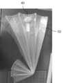
도 2는 종래 기술에 따라 평면형으로 제작한 라이너(50)를 접은 상태를 나타내는 사진이다.2 is a photograph showing a state in which a
종래에는 세로 방향으로는 부채를 접듯이 접고 라이너(50)의 하단부에서 가로 방향으로 접어 올린다.Conventionally, the fan is folded in the longitudinal direction such that it is folded in the transverse direction at the lower end of the
평면형으로 제작한 라이너(50)는 블로잉 이후 몸체(10)와 닿는 라이너의 바닥면 부분에 주름이 형성될 수 있다. 평면형 라이너(50)는 화학 물질이 저장되는 경우 화학 물질이 몸체(10)의 바닥에 닿도록 그 높이를 충분히 크게 설계하므로 블로잉시 생성된 주름은 화학 물질이 담긴 상태에서도 그대로 유지될 가능성이 크다.The
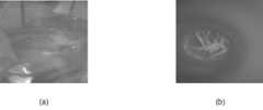
도 3은 도 2의 라이너(50)를 실험을 위하여 투명하게 제작된 몸체(10)에 삽입하고 블로잉한 후의 모습을 나타낸 것으로서 (b)는 (a)의 주름 부분을 확대한 사진이다.Fig. 3 shows a state after the
도 4는 주름에 의한 문제점을 나타낸 도면이다.4 is a view showing a problem caused by wrinkles.
전술한 바와 같이 몸체(10)와 라이너(50) 사이에 가해지는 압력으로 인하여 화학 물질이 딥튜브(60)를 통해 외부로 배출된다.The chemical is discharged to the outside through the
그러나 라이너(50)를 블로잉하는 과정에서 주름(70)이 발생하면 주름(70)에 의하여 화학 물질(80)이 갇히는 현상이 발생한다. 이렇게 갇힌 화학 물질은 딥튜브(60)를 통해 외부로 배출되지 못하여 결국 낭비된다.However, when the
이에 따라 상대적으로 적은 비용으로 제조된 평면형 라이너(50)를 사용하면서도 화학 물질의 잔량을 줄이기 위한 대책이 요구되고 있다.Accordingly, a countermeasure for reducing the remaining amount of chemical materials is required while using the
본 기술은 블로잉시 주름의 발생 가능성을 크게 줄일 수 있는 라이너와 그 접는 방법을 제공한다.The present technology provides a liner and method of folding that can significantly reduce the likelihood of wrinkling during blowing.
본 발명의 일 실시예에 의한 라이너는 주입구가 부착된 평면의 상면 부재; 및 주변부에서 상면 부재와 결합되는 평면의 하면 부재를 포함하되, 제 1 방향에 평행하도록 형성된 둘 또는 그 이상의 제 1 접는선과 제 1 방향에 수직인 제 2 방향에 평행하도록 형성된 둘 또는 그 이상의 제 2 접는선을 포함하고, 제 1 접는선에 따라 접힌 후 제 1 방향에 평행한 밴드가 형성된다.A liner according to an embodiment of the present invention includes a planar upper surface member having an injection port; And a planar lower surface member coupled to the top surface member at the periphery, wherein the two or more first fold lines formed to be parallel to the first direction and the two or more second fold lines formed to be parallel to the second direction perpendicular to the first direction And a band parallel to the first direction is formed after being folded along the first folding line.
본 발명의 일 실시예에 의한 라이너에서 상기 밴드는 상기 라이너의 두 단부 사이에 위치할 수 있다.In a liner according to an embodiment of the present invention, the band may be located between the two ends of the liner.
본 발명의 일 실시예에 의한 라이너에서 제 1 접는선은 제 1-1 접는선 및 제 1-1 접는선과 상기 라이너의 일단 사이의 제 1-2 접는선을 포함할 수 있다.In the liner according to an embodiment of the present invention, the first folding line may include a first fold line and a first fold line and a first fold line between the first fold line and the one end of the liner.
본 발명의 일 실시예에 의한 라이너에서 제 1-1 접는선과 제 1-2 접는선 사이의 폭은 상기 제 1-2 접는선과 상기 라이너의 일단 사이의 폭보다 작을 수 있다.In the liner according to an embodiment of the present invention, the width between the first-first folding line and the first-second folding line may be smaller than the width between the first-second folding line and the one end of the liner.
본 발명의 일 실시예에 의한 라이너에서 제 1-1 접는선은 라이너의 중심을 지날 수 있다.In the liner according to an embodiment of the present invention, the 1-1 line of folding may pass through the center of the liner.
본 발명의 일 실시예에 의한 라이너에서 제 2 접는선은 산을 형성하는 제 2-1 접는선과 골을 형성하는 제 2-2 접는선을 포함하고, 제 2-1 접는선과 제 2-2 접는선은 라이너를 지나는 중심선을 기준으로 좌우 대칭으로 배치될 수 있다.In the liner according to an embodiment of the present invention, the second folding line includes a 2-1 folding line forming an acid and a 2-2 folding line forming a valley, and the 2-1 folding line and the 2-2 folding line The lines may be arranged symmetrically with respect to the centerline passing through the liner.
본 발명의 일 실시예에 의한 라이너에서 상면 부재 및 하면 부재는 사각형일 수 있다.In the liner according to an embodiment of the present invention, the top surface member and the bottom surface member may be rectangular.
본 발명의 일 실시예에 의한 라이너를 접는 방법은 주입구가 부착된 평면의 상면 부재; 및 주변부에서 상면 부재와 결합되는 평면의 하면 부재를 포함하는 라이너를 접는 방법으로서, 제 1 방향에 평행하도록 형성된 둘 또는 그 이상의 제 1 접는선에 따라 라이너를 접어 밴드를 형성하는 제 1 단계 및 제 1 방향에 수직인 제 2 방향에 평행하도록 형성된 둘 또는 그 이상의 제 2 접는선에 따라 라이너를 접는 제 2 단계를 포함할 수 있다.A method of folding a liner according to an embodiment of the present invention includes: a planar upper surface member having an injection port; And a planar lower surface member joined to the top surface member at the peripheral portion, the method comprising: a first step of folding the liner along two or more first fold lines formed parallel to the first direction to form a band; And a second step of folding the liner along two or more second fold lines formed to be parallel to a second direction perpendicular to the one direction.
본 발명의 일 실시예에 의한 라이너의 접는 방법에서 밴드는 라이너의 두 단부 사이에 형성될 수 있다.In a method of folding a liner according to an embodiment of the present invention, a band may be formed between the two ends of the liner.
본 발명의 일 실시예에 의한 라이너의 접는 방법에서 제 1 접는선은 제 1-1 접는선 및 제 1-1 접는선과 라이너의 일단 사이의 제 1-2 접는선을 포함하고, 제 1 단계는 라이너의 일단을 제 1-1 접는선에 따라 접어 올리는 단계 및 일단을 제 1-2 접는선에 따라 접어 내리는 단계를 포함할 수 있다.In a method of folding a liner according to an embodiment of the present invention, the first folding line includes a first fold line and a first fold line between the first fold line and the first fold line, Folding one end of the liner along the first fold line and folding one end along the first fold line.
본 발명의 일 실시예에 의한 라이너의 접는 방법에서 제 1-1 접는선은 라이너의 중심을 지날 수 있다.In the folding method of the liner according to an embodiment of the present invention, the 1-1 line of folding may pass through the center of the liner.
본 발명의 일 실시예에 의한 라이너의 접는 방법에서 제 2 접는선은 산을 형성하는 제 2-1 접는선과 골을 형성하는 제 2-2 접는선을 포함하고, 제 2 단계는 제 2-1 접는선에 따라 산을 형성하도록 접는 단계, 제 2-2 접는선에 따라 골을 형성하도록 접는 단계를 포함할 수 있다.In the method of folding a liner according to an embodiment of the present invention, the second folding line includes a 2-1 folding line forming an acid and a 2-2 folding line forming a valley, Folding to form an acid along the fold line, and folding to form a corrugation along the fold line 2-2.
본 발명의 일 실시예에 의한 라이너의 접는 방법에서 제 2-1 접는선과 제 2-2 접는선은 라이너를 지나는 중심선을 기준으로 좌우 대칭으로 배치될 수 있다.In the method of folding a liner according to an embodiment of the present invention, the 2-1 folding line and the 2-2 folding line may be arranged symmetrically with respect to the center line passing the liner.
본 발명의 일 실시예에 의한 라이너의 접는 방법에서 상면 부재 및 하면 부재는 사각형일 수 있다.In the method of folding a liner according to an embodiment of the present invention, the upper surface member and the lower surface member may be rectangular.
본 발명에 의하여 접힌 라이너를 압력 용기에 장착하고 블로잉하는 경우 종래에 비하여 주름의 개수 및 크기가 줄어들어 화학 물질을 사용한 이후 잔량이 현저하게 줄어드는 효과가 있다. 또한 본 발명에 의한 라이너는 종래의 입체형으로 제작된 라이너에 비하여 제조 단가는 현저하게 낮으면서 화학 물질 잔량의 차이는 크지 않아 제품의 가격 대비 화학 물질 잔량 측면에서 우수하다.According to the present invention, when the folded liner is mounted on a pressure vessel and blown, the number and size of the wrinkles are reduced compared with the prior art, and the residual amount after using the chemical substance is remarkably reduced. In addition, the liner according to the present invention has a significantly lower manufacturing cost than the conventional three-dimensionally manufactured liner, and the difference in the remaining amount of the chemical substance is not so large, which is superior in terms of the amount of the chemical substance to the price of the product.
도 1은 종래 기술에 의한 압력 용기를 나타내는 도면.
도 2는 종래 기술에 의한 라이너를 나타내는 사진.
도 3은 종래 기술의 문제점을 나타내는 사진.
도 4는 종래 기술의 문제점을 나타내는 도면.
도 5는 본 발명의 일 실시예에 의한 라이너를 나타내는 도면.
도 6은 도 5의 A-A선에 따른 단면도.
도 7, 8은 본 발명의 일 실시예에 의한 라이너를 접는 방법을 나타낸 도면.
도 9는 본 발명의 일 실시예에 따라 접힌 라이너의 사진.
도 10, 11은 본 발명의 다른 실시예에 의한 라이너를 접는 방법을 나타낸 도면.
도 12는 본 발명의 다른 실시예에 따라 접힌 라이너의 사진.
도 13은 본 발명의 효과를 나타내는 사진.BRIEF DESCRIPTION OF THE DRAWINGS FIG. 1 shows a pressure vessel according to the prior art; FIG.
2 is a photograph showing a liner according to the prior art;
3 is a photograph showing the problem of the prior art.
4 shows a problem of the prior art.
5 shows a liner according to an embodiment of the invention.
6 is a cross-sectional view taken along line AA of Fig.
Figures 7 and 8 illustrate a method of folding a liner according to one embodiment of the present invention.
Figure 9 is a photograph of a folded liner according to one embodiment of the present invention.
10 and 11 illustrate a method of folding a liner according to another embodiment of the present invention.
12 is a photograph of a folded liner according to another embodiment of the present invention.
13 is a photograph showing the effect of the present invention.
이하에서는 첨부한 도면을 참조하여 본 발명의 실시예에 대해서 상세히 설명한다. 이하의 설명에서 동일한 참조 부호는 실질적으로 동일한 대상을 지시한다.Hereinafter, embodiments of the present invention will be described in detail with reference to the accompanying drawings. In the following description, the same reference numerals denote substantially the same objects.
도 5는 본 발명의 일 실시예에 의한 라이너(50)의 평면도이고, 도 6은 도 5의 A-A 선에 따른 단면도이다.FIG. 5 is a plan view of the
본 발명의 일 실시예에 의한 라이너(50)에는 피트먼트(40)가 부착된다.A
라이너(50)는 비닐 등의 가요성 재질을 가진 부재를 사각형 예를 들어 직사각형 형태로 재단하고 이들을 둘 이상 중첩한 후 테두리 부위의 접합부(50b)에 열을 가하는 등의 방식으로 접합하여 형성한다.The
도 6에 도시된 바와 같이 라이너(50)는 상면 부재(50u)와 하면 부재(50b)를 접합부(50b)에 열을 가하여 형성한다.As shown in FIG. 6, the
다른 실시예에서 상면 부재(50u)와 하면 부재(50b) 각각의 개수는 1 또는 2 이상이 될 수 있다.In other embodiments, the number of the
피트먼트(40)는 상면 부재(50u)에 접착 등의 방법으로 결합된다. 이에 따라 피트먼트(40)의 구멍을 통해 라이너(40)의 내부에 화학 물질을 저장할 수 있게 된다.The
본 발명의 일 실시예에 의한 라이너(50)는 화학 물질 저장 용기의 몸체(10)에 용이하게 삽입하기 위하여 소정의 형태로 접힌 상태에 있는 것이 바람직하다.The
접힌 상태의 라이너(50)를 몸체(10) 내에 삽입한 이후 블로잉을 통해 라이너(50)를 부풀리게 되는데 본 발명에서는 이하에서 개시하는 방법에 의해 라이너(50)를 접음으로써 블로잉 후 라이너(50)의 바닥면에 주름이 생기는 현상을 크게 줄일 수 있다.The
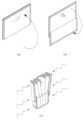
도 7은 본 발명의 제 1 실시예에 의한 라이너(50)를 접는 방법을 나타낸 전개도이고, 도 8은 도 7의 전개도에 따라 라이너(50)를 접는 순서를 설명하는 도면이다.FIG. 7 is an exploded view showing a method for folding the
도 7의 도면은 20L용으로 사용되는 라이너(50)에 관한 것으로서 가로의 길이는 494mm이고, 세로의 길이는 648mm이다.The figure in Fig. 7 relates to a
라이너(50)는 피트먼트(40)에 인접한 제 1 변(51), 제 1 변(51) 반대쪽의 제 2 변(52), 좌우의 제 3 변(53) 및 제 4 변(54)을 포함한다.The
먼저 제 1 변(51)에 평행한 제 1 수평선(U)에 따라 제 2 변(52)을 제 1 변(51) 방향으로 접어 올린다. 본 실시예에서 제 1 수평선(U)은 제 3 변(53)과 제 4 변(54)의 중심을 지난다.The
다음으로 제 2 수평선(D)에 따라 제 2 변(52)을 제 1 변(51)의 반대 방향으로 접어 내린다.Next, along the second horizontal line (D), the second side (52) is folded down in the direction opposite to the first side (51).
본 실시예에서 제 1 수평선(U)과 제 2 수평선(D)에 의해 형성되는 밴드의 폭은 80 mm이다.In this embodiment, the width of the band formed by the first horizontal line U and the second horizontal line D is 80 mm.
다음으로 제 3 변(53)과 제 4 변(54)에 실질적으로 평행하게 형성된 수직선들(M, V)에 따라 라이너(50)를 부채를 접듯이 접는다. 이때 피트먼트(40)에 인접한 두 라인은 피트먼트(40)로 인하여 비스듬하게 형성될 수 있다.Next, the
제 1 수직선(M)은 산을 형성하고, 제 2 수직선(V)은 골을 형성한다. 제 1 수직선(M)과 제 2 수직선(V)은 피트먼트(40)의 좌우에 대칭적으로 배치되는 것이 바람직하다.The first vertical line M forms an acid, and the second vertical line V forms a valley. It is preferable that the first vertical line M and the second vertical line V are symmetrically arranged on the left and right sides of the
도 9는 본 발명의 일 실시예에 의한 라이너(50)를 접은 상태를 나타낸 사진이다.9 is a photograph showing a state in which the
(a)는 접은 후의 제 1 변(51)의 모양을 나타내고, (b)는 접은 후의 제 2 변(52)의 모양을 나타내고, (c)는 접은 후의 전체 모양을 나타낸다.(a) shows the shape of the
도 9의 사진은 피트먼트(40)에 뚜껑(41)이 씌워진 실시예를 나타낸다. 뚜껑(41)은 피트먼트(40)를 통해 라이너(50) 내에 이물질이 들어가는 것을 방지한다.9 shows an embodiment in which the
사진과 같이 라이너(50)는 투명한 비닐 재질로 제작될 수 있는데, (c)와 같이 제 1 수평선(U)과 제 2 수평선(D) 사이의 밴드 부분은 라이너(50)가 세 번 겹쳐진 상태이므로 다른 부분에 비하여 상대적으로 불투명하게 보인다.As shown in the photograph, the
도 10 내지 도 12는 본 발명의 제 2 실시예에 의한 라이너(50)를 접는 방법을 나타낸 도면이다.10 to 12 are views showing a method of folding the
제 2 실시예에서 라이너(50)는 40L의 화학 물질을 저장하기 위한 것으로서 가로의 길이는 570mm, 세로의 길이는 900mm이다.In the second embodiment, the
본 실시예에서 제 1 수평선(U)과 제 2 수평선(D)에 의해 형성되는 밴드의 폭은 150mm 이다.In this embodiment, the width of the band formed by the first horizontal line U and the second horizontal line D is 150 mm.
제 2 실시예에 의한 라이너(50)의 경우 제 1 실시예에 의한 라이너(50)에 비하여 제 2 수직선(V)이 좌우에 각각 하나씩 더 있다.In the case of the
이에 따라 접은 후에 제 1 변(51)과 제 2 변(52)의 모양은 도 12에 도시된 바와 같이 제 1 실시예의 경우와는 다소 상이하다.Accordingly, the shapes of the
도 8의 제 1 실시예와 도 11의 제 2 실시예는 제 1 수평선과 제 2 수평선에 따라 라이너를 접어 밴드를 형성하고 제 2 수직선에 따라 부채를 접듯이 라이너를 접는 방법을 개시하고 있다.The first embodiment of FIG. 8 and the second embodiment of FIG. 11 disclose a method of folding a liner along a first horizontal line and a second horizontal line to form a band and folding the liner along a second vertical line.
이러한 실시예를 기준으로 추가적인 접는 단계를 수행하는 다른 실시예 역시 본 발명의 권리범위에 포함될 수 있다. 예를 들어 도 8(c) 및 도 11(c)와 같이 접힌 상태의 라이너의 하단부를 도 2에 도시된 바와 같이 접어 올릴 수 있다. 이 경우 라이너의 세로 방향 길이를 줄일 수 있다.Other embodiments that perform additional folding steps based on these embodiments may also be included within the scope of the present invention. For example, the lower end of the liner in the folded state as shown in Figs. 8 (c) and 11 (c) can be folded up as shown in Fig. In this case, the longitudinal length of the liner can be reduced.
도 13은 본 발명의 효과를 나타내는 사진이다.13 is a photograph showing the effect of the present invention.
도 13은 라이너(50)를 실험을 위하여 투명하게 제작된 몸체(10)에 삽입하고 블로잉한 후의 모습을 나타낸 것으로서 (b)는 (a)에서 주름 부위를 확대한 도면이다.Fig. 13 shows a state after the
도 13(b)를 도 3(b)와 대비하면 주름의 개수 및 높이가 종래에 비하여 줄어든 것을 확인할 수 있다. 이에 따라 주름 사이에 잔존하는 화학 물질의 양이 줄어들고 결과적으로 화학 물질의 낭비를 방지할 수 있다.13 (b) is compared with FIG. 3 (b), it can be seen that the number of wrinkles and the height of the wrinkles are reduced as compared with the prior art. As a result, the amount of chemicals remaining between the wrinkles is reduced, and consequently wasted chemicals can be prevented.
20L 크기의 라이너(50)에 있어서 본 발명과 종래 기술에 의한 경우 화학 물질 잔량을 비교하면 다음의 표 1과 같다.In the case of the 20L
위의 표와 같이 종래 기술에 의한 라이너에 비하여 본 발명에 의한 라이너에서 화학 물질 잔량이 약 60% 정도 줄어들었음을 알 수 있다.As shown in the above table, it can be seen that the remaining amount of chemical substances in the liner according to the present invention is reduced by about 60% as compared with the conventional liner.
40L 크기의 라이너(50)에 있어서 본 발명과 종래 기술에 의한 경우 화학 물질 잔량을 비교하면 다음의 표 2와 같다.In the case of the 40L-
위의 표와 같이 종래 기술에 의하여 라이너를 접는 경우에 비하여 본 발명에 의하여 라이너를 접는 경우 화학 물질 잔량이 약 67% 정도 줄어들었음을 알 수 있다.As shown in the table above, when the liner is folded according to the present invention, the remaining amount of the chemical is reduced by about 67% compared to the case where the liner is folded by the conventional technique.
이상에서 도면을 참조하여 본 발명의 실시예를 개시하였다. 이상의 개시는 설명을 위한 것으로서 본 발명의 권리범위를 한정하는 것은 아니며, 본 발명의 권리범위는 이하의 특허청구범위에 문언적으로 기재된 범위와 그 균등범위에 의해 정해진다.The embodiments of the present invention have been described with reference to the drawings. The scope of the present invention is not limited to the scope of the present invention, and the scope of the present invention is defined by the scope of the following claims and their equivalents.
10: 몸체
20: 주입구
30: 리테이너
40: 피트먼트
41: 뚜껑
50: 라이너
51: 제 1 변
52: 제 2 변
53: 제 3 변
54: 제 4 변
50b: 접합부
50u: 상면 부재
50d: 하면 부재
60: 딥튜브
70: 주름
80: 화학 물질10: Body
20: inlet
30: retainer
40: Fitment
41: Lid
50: Liner
51: 1st side
52: second side
53: The third side
54: The fourth side
50b:
50u: upper surface member
50d: lower surface member
60: dip tube
70: Wrinkles
80: Chemicals
Claims (14)
Translated fromKorean주변부(50b)에서 상기 상면 부재(50u)와 결합되는 평면의 하면 부재(50d)
를 포함하는 라이너(50)로서,
상기 상면 부재(50u)와 상기 하면 부재(50d)는 제 1 방향에 평행한 둘 또는 그 이상의 제 1 접는선(U, D)과 상기 제 1 방향에 수직인 제 2 방향에 평행한 둘 또는 그 이상의 제 2 접는선(M, V)에 따라 함께 접히되, 상기 상면 부재(50u) 및 상기 하면 부재(50d)는 상기 제 1 접는선(U, D)에 따라 함께 접힌 후 상기 제 1 방향에 평행한 밴드가 형성되는 라이너.A planar upper surface member 50u having an injection port 40 attached thereto; And
A planar lower surface member 50d joined to the upper surface member 50u at the peripheral portion 50b,
A liner (50)
The upper surface member 50u and the lower surface member 50d are formed of two or more first folding lines U and D parallel to the first direction and two or more first folding lines U and D parallel to the second direction perpendicular to the first direction, The upper surface member 50u and the lower surface member 50d are folded along the first folding lines U and D and then folded along the second folding lines M and V in the first direction A liner in which parallel bands are formed.
제 1 방향에 평행한 둘 또는 그 이상의 제 1 접는선(U, D)에 따라 상기 상면 부재(50u)와 상기 하면 부재(50d)를 함께 접어 밴드를 형성하는 제 1 단계 및
상기 제 1 방향에 수직인 제 2 방향에 평행한 둘 또는 그 이상의 제 2 접는선(M, V)에 따라 상기 상면 부재(50u)와 상기 하면 부재(50d)를 함께 접는 제 2 단계
를 포함하는 라이너의 접는 방법.A planar upper surface member 50u having an injection port 40 attached thereto; And a planar bottom member (50d) joined to the top surface member (50u) at a peripheral portion (50b), the method comprising:
A first step of folding together the upper surface member 50u and the lower surface member 50d along two or more first folding lines U and D parallel to the first direction to form a band,
A second step of folding the upper surface member 50u and the lower surface member 50d together along two or more second fold lines (M, V) parallel to a second direction perpendicular to the first direction,
Of the liner.
상기 일단(52)을 상기 제 1-1 접는선(U)에 따라 접어 올리는 단계 및
상기 일단(52)을 상기 제 1-2 접는선(D)에 따라 접어 내리는 단계
를 포함하는 라이너의 접는 방법.The method of claim 8, wherein the first fold line comprises a first 1-2 fold line (D) between the 1-1 first fold line (U) and the 1-1 fold line (U) and one end (52) Wherein the first step comprises:
Folding the one end (52) along the first fold line (U) and
Folding the one end (52) along the first and second folding lines (D)
Of the liner.
상기 제 2-1 접는선(M)에 따라 산을 형성하도록 접는 단계 및
상기 제 2-2 접는선(V)에 따라 골을 형성하도록 접는 단계
를 포함하는 라이너의 접는 방법.The method of claim 8, wherein the second fold line comprises a second fold line (M) forming an acid and a second fold line (V) forming a valley,
Folding to form an acid along the second-1 fold line (M); and
Folding so as to form a corrugation along the second-2 folding line (V)
Of the liner.
Priority Applications (1)
| Application Number | Priority Date | Filing Date | Title |
|---|---|---|---|
| KR20140120991AKR101494628B1 (en) | 2014-09-12 | 2014-09-12 | Liner for storing chemical and folding method therof |
Applications Claiming Priority (1)
| Application Number | Priority Date | Filing Date | Title |
|---|---|---|---|
| KR20140120991AKR101494628B1 (en) | 2014-09-12 | 2014-09-12 | Liner for storing chemical and folding method therof |
Publications (1)
| Publication Number | Publication Date |
|---|---|
| KR101494628B1true KR101494628B1 (en) | 2015-02-23 |
Family
ID=52594045
Family Applications (1)
| Application Number | Title | Priority Date | Filing Date |
|---|---|---|---|
| KR20140120991ACeasedKR101494628B1 (en) | 2014-09-12 | 2014-09-12 | Liner for storing chemical and folding method therof |
Country Status (1)
| Country | Link |
|---|---|
| KR (1) | KR101494628B1 (en) |
Citations (4)
| Publication number | Priority date | Publication date | Assignee | Title |
|---|---|---|---|---|
| KR20070015964A (en)* | 2004-05-20 | 2007-02-06 | 인베브 에스.에이. | Folded Alcoholic Drink Bags and Methods |
| KR20080005290A (en)* | 2005-04-25 | 2008-01-10 | 어드밴스드 테크놀러지 머티리얼즈, 인코포레이티드 | Material Storage and Dispensing Packages and Storage and Dispensing Methods |
| KR20110036007A (en)* | 2009-07-09 | 2011-04-06 | 어드밴스드 테크놀러지 머티리얼즈, 인코포레이티드 | How to supply high purity materials to liner-based storage systems, liners and semiconductor processes |
| KR101280671B1 (en)* | 2012-02-06 | 2013-07-01 | 어드밴스드 테크놀러지 머티리얼즈, 인코포레이티드 | Folded liner for use with an overpack and methods of manufacturing the same |
- 2014
- 2014-09-12KRKR20140120991Apatent/KR101494628B1/ennot_activeCeased
Patent Citations (4)
| Publication number | Priority date | Publication date | Assignee | Title |
|---|---|---|---|---|
| KR20070015964A (en)* | 2004-05-20 | 2007-02-06 | 인베브 에스.에이. | Folded Alcoholic Drink Bags and Methods |
| KR20080005290A (en)* | 2005-04-25 | 2008-01-10 | 어드밴스드 테크놀러지 머티리얼즈, 인코포레이티드 | Material Storage and Dispensing Packages and Storage and Dispensing Methods |
| KR20110036007A (en)* | 2009-07-09 | 2011-04-06 | 어드밴스드 테크놀러지 머티리얼즈, 인코포레이티드 | How to supply high purity materials to liner-based storage systems, liners and semiconductor processes |
| KR101280671B1 (en)* | 2012-02-06 | 2013-07-01 | 어드밴스드 테크놀러지 머티리얼즈, 인코포레이티드 | Folded liner for use with an overpack and methods of manufacturing the same |
Similar Documents
| Publication | Publication Date | Title |
|---|---|---|
| US9586742B2 (en) | Blister package with divided interior volume | |
| CN205114050U (en) | Multilayer formula air packing plant | |
| WO2010148461A3 (en) | Collapsible bottle, method of manufacturing a blank for such bottle and beverage-filled bottle dispensing system | |
| US5356070A (en) | Partitioned paperboard food tray | |
| CN107264911A (en) | The manufacture method of package sleeve, package and package | |
| US20080193055A1 (en) | Inflatable bag for bottles packaging | |
| KR20110018889A (en) | Improved Vessel Blanks and Vessels | |
| CN109641681A (en) | Sheeting container | |
| CN109071060B (en) | Synthetic resin container | |
| US20170369224A1 (en) | Inflatable airbag without heat-resisting layer andmanufacturing method thereof | |
| KR20120070505A (en) | Containment tray | |
| JP6363009B2 (en) | Plastic bottle | |
| CN105916776A (en) | Plastic bottle | |
| ITUA20163895A1 (en) | PACKAGING FOR THE CONTAINMENT OF OBJECTS, PARTICULARLY BOTTLES | |
| KR101494628B1 (en) | Liner for storing chemical and folding method therof | |
| KR102014617B1 (en) | Combination of outer container and liquid storage container, method for producing same, and liquid storage container | |
| JP5472792B2 (en) | Synthetic resin housing | |
| TW201509760A (en) | Freestanding pouch | |
| KR20180018027A (en) | Tray for carrying contact lens | |
| JP2009057085A (en) | Synthetic resin bottle | |
| CN207292976U (en) | Air-packing devices | |
| ES2318262T3 (en) | FLEXIBLE MATERIAL CONTAINER IN THE FORM OF A TRAY AND METHOD AND RELATIVE MANUFACTURING EQUIPMENT. | |
| CN105228908A (en) | Comprise the jerrycan of the domed bottom with variable base | |
| JP6341428B2 (en) | Synthetic resin round frame | |
| CN207275257U (en) | Multifunctional portable angle support unit, component and packaging structure |
Legal Events
| Date | Code | Title | Description |
|---|---|---|---|
| PA0109 | Patent application | Patent event code:PA01091R01D Comment text:Patent Application Patent event date:20140912 | |
| PA0201 | Request for examination | ||
| PA0302 | Request for accelerated examination | Patent event date:20140918 Patent event code:PA03022R01D Comment text:Request for Accelerated Examination Patent event date:20140912 Patent event code:PA03021R01I Comment text:Patent Application | |
| PE0902 | Notice of grounds for rejection | Comment text:Notification of reason for refusal Patent event date:20141027 Patent event code:PE09021S01D | |
| E701 | Decision to grant or registration of patent right | ||
| PE0701 | Decision of registration | Patent event code:PE07011S01D Comment text:Decision to Grant Registration Patent event date:20150210 | |
| GRNT | Written decision to grant | ||
| PR0701 | Registration of establishment | Comment text:Registration of Establishment Patent event date:20150212 Patent event code:PR07011E01D | |
| PR1002 | Payment of registration fee | Payment date:20150212 End annual number:3 Start annual number:1 | |
| PG1601 | Publication of registration | ||
| J206 | Request for trial to confirm the scope of a patent right | ||
| PJ0206 | Trial to confirm the scope of a patent | Patent event code:PJ02062R01D Patent event date:20150729 Comment text:Request for Trial Patent event code:PJ02061E01I Patent event date:20150212 Comment text:Registration of Establishment Decision date:20160520 Request date:20150729 Appeal identifier:2015100004085 Appeal kind category:Confirmation of the scope of right_affirmative | |
| J301 | Trial decision | Free format text:TRIAL DECISION FOR CONFIRMATION OF THE SCOPE OF RIGHT_AFFIRMATIVE REQUESTED 20150729 Effective date:20160520 | |
| PJ1301 | Trial decision | Patent event code:PJ13011S02D Patent event date:20160520 Comment text:Trial Decision for Confirmation of the Scope of a Right (Patent, Utility Model, Industrial Design) Appeal kind category:Confirmation of the scope of right_affirmative Request date:20150729 Decision date:20160520 Appeal identifier:2015100004085 | |
| J204 | Request for invalidation trial [patent] | ||
| PJ0204 | Invalidation trial for patent | Patent event date:20160922 Comment text:Request for Trial Patent event code:PJ02042R01D Patent event date:20150212 Comment text:Registration of Establishment Patent event code:PJ02041E01I Appeal kind category:Invalidation Request date:20160922 Decision date:20170214 Appeal identifier:2016100002913 | |
| J301 | Trial decision | Free format text:TRIAL NUMBER: 2016100002913; TRIAL DECISION FOR INVALIDATION REQUESTED 20160922 Effective date:20170214 | |
| PJ1301 | Trial decision | Patent event code:PJ13011S05D Patent event date:20170214 Comment text:Trial Decision on Invalidation (Patent, Utility Model, Industrial Design) Appeal kind category:Invalidation Request date:20160922 Decision date:20170214 Appeal identifier:2016100002913 | |
| PC2102 | Extinguishment | Termination category:Others Termination date:20170508 |