KR101494430B1 - Machine for drip coffee - Google Patents
Machine for drip coffeeDownload PDFInfo
- Publication number
- KR101494430B1 KR101494430B1KR20140052698AKR20140052698AKR101494430B1KR 101494430 B1KR101494430 B1KR 101494430B1KR 20140052698 AKR20140052698 AKR 20140052698AKR 20140052698 AKR20140052698 AKR 20140052698AKR 101494430 B1KR101494430 B1KR 101494430B1
- Authority
- KR
- South Korea
- Prior art keywords
- container
- hole
- water
- coffee
- discharged
- Prior art date
- Legal status (The legal status is an assumption and is not a legal conclusion. Google has not performed a legal analysis and makes no representation as to the accuracy of the status listed.)
- Active
Links
Images


Classifications
- A—HUMAN NECESSITIES
- A47—FURNITURE; DOMESTIC ARTICLES OR APPLIANCES; COFFEE MILLS; SPICE MILLS; SUCTION CLEANERS IN GENERAL
- A47J—KITCHEN EQUIPMENT; COFFEE MILLS; SPICE MILLS; APPARATUS FOR MAKING BEVERAGES
- A47J31/00—Apparatus for making beverages
- A47J31/02—Coffee-making machines with removable extraction cups, to be placed on top of drinking-vessels i.e. coffee-makers with removable brewing vessels, to be placed on top of beverage containers, into which hot water is poured, e.g. cafe filter
- A—HUMAN NECESSITIES
- A47—FURNITURE; DOMESTIC ARTICLES OR APPLIANCES; COFFEE MILLS; SPICE MILLS; SUCTION CLEANERS IN GENERAL
- A47J—KITCHEN EQUIPMENT; COFFEE MILLS; SPICE MILLS; APPARATUS FOR MAKING BEVERAGES
- A47J31/00—Apparatus for making beverages
- A47J31/10—Coffee-making apparatus, in which the brewing vessel, i.e. water heating container, is placed above or in the upper part of the beverage containers i.e. brewing vessel; Drip coffee-makers with the water heating container in a higher position than the brewing vessel
- A—HUMAN NECESSITIES
- A47—FURNITURE; DOMESTIC ARTICLES OR APPLIANCES; COFFEE MILLS; SPICE MILLS; SUCTION CLEANERS IN GENERAL
- A47J—KITCHEN EQUIPMENT; COFFEE MILLS; SPICE MILLS; APPARATUS FOR MAKING BEVERAGES
- A47J31/00—Apparatus for making beverages
- A47J31/06—Filters or strainers for coffee or tea makers ; Holders therefor
- A—HUMAN NECESSITIES
- A47—FURNITURE; DOMESTIC ARTICLES OR APPLIANCES; COFFEE MILLS; SPICE MILLS; SUCTION CLEANERS IN GENERAL
- A47J—KITCHEN EQUIPMENT; COFFEE MILLS; SPICE MILLS; APPARATUS FOR MAKING BEVERAGES
- A47J31/00—Apparatus for making beverages
- A47J31/44—Parts or details or accessories of beverage-making apparatus
- A47J31/4403—Constructional details
- A47J31/4475—Hot water outlets for drip coffee makers
- A47J31/4478—Spreader plates
- A—HUMAN NECESSITIES
- A47—FURNITURE; DOMESTIC ARTICLES OR APPLIANCES; COFFEE MILLS; SPICE MILLS; SUCTION CLEANERS IN GENERAL
- A47J—KITCHEN EQUIPMENT; COFFEE MILLS; SPICE MILLS; APPARATUS FOR MAKING BEVERAGES
- A47J31/00—Apparatus for making beverages
- A47J31/44—Parts or details or accessories of beverage-making apparatus
- A47J31/46—Dispensing spouts, pumps, drain valves or like liquid transporting devices
Landscapes
- Engineering & Computer Science (AREA)
- Food Science & Technology (AREA)
- Apparatus For Making Beverages (AREA)
Abstract
Translated fromKoreanDescription
Translated fromKorean본 발명은 드립 커피 제조기에 관한 것으로서, 특히 물의 표면장력과 점성을 이용하여, 커피 가루 위의 넓은 영역에 비교적 작은 유량으로 약 3분 이내에 물을 서서히 뿌려줄 수 있는 드립 커피 제조기에 관한 것이다.The present invention relates to a drip coffee maker and, more particularly, to a drip coffee maker capable of slowly spraying water within a relatively small flow rate over a large area above a coffee ground within about 3 minutes, using water surface tension and viscosity.
드립 커피(Drip Coffee)란, 커피 원두를 잘게 빻은 커피 가루에 끓는 물을 부어 걸러 내는 커피를 말한다.Drip Coffee refers to coffee that pours boiling water into coffee ground beans and ground coffee beans.
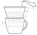
이러한, 드립 커피는 도 1에 도시된 바와 같이, 먼저 분쇄된 커피 가루(C)를 종이로 된 필터(F)에 담아 깔때기 모양의 드립 커피 제조기(D)에 올려놓고, 주전자(K)를 손으로 잡아서 물을 상기 드립 커피 제조기(D)의 중앙으로부터 원을 그리며 안팎으로 양을 조절해가며 붓는다.As shown in FIG. 1, the drip coffee is prepared by putting the pulverized coffee powder (C) in a paper filter (F), placing it on a funnel-shaped drip coffee maker (D) , And water is poured into the circle of the drip coffee maker (D) in a circle and adjusted in and out.
특히, 드립 커피의 경우에는 1차적으로 약간의 물을 먼저 커피 가루(C)에 투입하는 선행작업을 하게 되면, 커피 가루(C)의 세포벽에 존재하는 커피 성분을 미리 불려주는 상태가 되고, 이어서 2차적으로 비교적 다량의 물을 투입하게 되면 커피 가루(C)의 세포 내에 존재하는 이산화탄소가 팽창하면서 진한 커피 성분을 추출되며, 추출된 커피는 커피 용기(B)로 떨어져 채워진다.Particularly, in the case of drip coffee, if a precedent operation is performed in which a small amount of water is first introduced into the coffee powder C, the coffee component existing in the cell wall of the coffee powder C is preliminarily called, Secondly, when a relatively large amount of water is introduced, the carbon dioxide present in the cells of the coffee powder (C) expands, and the concentrated coffee component is extracted, and the extracted coffee is filled into the coffee container (B).
이와 같이 종래의 드립 커피 제조기(D)를 사용할 경우, 추출되는 드립 커피는 커피 가루(C)에 투입되는 물의 양과 물이 투입되는 속도 및 시간 등에 그 맛이 좌우되므로, 상기 드립 커피 제조기(D)에 물을 붓는 사람의 숙련도에 의하여 커피의 맛과 향이 크게 달라지게 되며, 정식 교육을 받고 오랜 경험을 쌓은 바리스타가 아닌 일반인의 경우 상기 드립 커피 제조기(D)에 물을 적절히 균일하게 공급하지 못하여 좋은 커피맛을 내기 어려운 문제점이 있다.When the conventional drip coffee maker (D) is used, the taste of the drip coffee extracted depends on the amount of water put into the coffee powder (C), the speed and time of the water input, The taste and the aroma of the coffee are largely changed by the skill of the person pouring the water into the drip coffee maker D. In the case of a general person who is not a barista who has acquired formal education and long experience, There is a problem that it is difficult to taste good coffee.
본 발명은 비전문가가 좋은 커피 맛을 내기 어렵다는 문제를 해결하기 위해 안출된 것으로서, 그 목적은 물의 표면장력과 점성을 이용하여, 커피 가루 위의 넓은 영역에 비교적 작은 유량으로 약 3분 이내에 물을 서서히 뿌려줄 수 있도록 구조가 개선된 드립 커피 제조기를 제공하기 위함이다.The object of the present invention is to solve the problem that a non-specialist is difficult to taste a good coffee taste. The object of the present invention is to use water surface tension and viscosity to slowly dissolve water in a relatively small flow rate on a coffee ground within about 3 minutes The present invention relates to a drip coffee maker having a structure which is capable of dispensing a drip coffee.
상기 목적을 달성하기 위하여 본 발명에 따른 드립 커피 제조기는, 커피 원두를 잘게 빻은 커피 가루에 물을 부어서 드립 커피를 제조하는 드립 커피 제조기에 있어서, 물을 수용하는 용기로서, 물이 아래로 배출될 수 있도록 하단부에 제1 관통공을 구비하는 제1 용기; 상기 제1 관통공으로부터 배출되는 물을 수용하는 용기로서, 상기 제1 용기의 하측에 배치되며, 내부에 수용된 물이 상기 커피 가루 위로 배출될 수 있도록 하단부에 복수 개의 제2 관통공을 구비하는 제2 용기; 상기 커피 가루와 상기 제2 관통공으로부터 배출되는 물을 수용하는 용기로서, 상기 제2 용기의 하측에 배치되며, 추출된 드립 커피가 아래로 배출될 수 있도록 하단부에 제3 관통공을 구비하는 제3 용기;를 포함하며, 상기 제1 관통공의 직경은 1.4 내지 1.9mm이며, 상기 제2 관통공의 직경은 0.4 내지 0.9mm이며, 상기 제2 용기에 수용되어 있는 물은, 물의 표면장력과 점성에 의하여 상기 제2 관통공을 통하여 미리 정한 단위 시간당 유량으로 서서히 배출되는 것을 특징으로 합니다.In order to achieve the above object, a drip coffee maker according to the present invention is a drip coffee maker for producing drip coffee by pouring water into a ground coffee flour, A first container having a first through-hole at a lower end thereof so as to be able to receive the first through-hole; And a plurality of second through holes disposed at a lower end of the container to allow water contained therein to be discharged onto the coffee ground, 2 containers; A container for receiving water discharged from the coffee powder and the second through hole, the container being disposed below the second container and having a third through hole at a lower end thereof so that the extracted drip coffee can be discharged downward; Wherein the first through hole has a diameter of 1.4 to 1.9 mm and the second through hole has a diameter of 0.4 to 0.9 mm and the water contained in the second container has a surface tension of water And gradually discharged through the second through hole at a predetermined flow rate per unit time due to viscosity.
여기서, 상기 제1 용기는, 하단부로 갈수록 내경이 감소하도록 미리 정한 경사각을 가지는 깔때기 형상으로서, 미리 정한 경사각을 가지는 뒤집힌 원뿔 또는 원뿔대 형상이며, 상기 제1 관통공이 상기 원뿔 또는 원뿔대의 중심축 상에 배치되어 있는 것이 바람직하다.Here, the first container may be an inverted cone having a predetermined angle of inclination or a truncated cone shape having a predetermined inclination angle such that the inner diameter decreases toward the lower end, and the first through hole may be formed on the central axis of the cone or truncated cone Or the like.
여기서, 상기 제1 용기는 160 내지 500ml의 물을 수용할 수 있는 크기의 용기이며, 상기 제2 용기는 20 내지 60ml의 물을 수용할 수 있는 크기의 용기인 것이 바람직하다.Preferably, the first container is a container having a size capable of accommodating 160 to 500 ml of water, and the second container is preferably a container having a size capable of accommodating 20 to 60 ml of water.
여기서, 상기 제1 용기는 상기 경사각이 60도 내지 70도인 것이 바람직하다.Preferably, the inclination angle of the first container is in a range of 60 to 70 degrees.
여기서, 상기 제2 용기는, 상기 제2 관통공이 상기 제1 관통공으로부터 하방으로 수직하게 연장된 가상의 수직선 위에 있지 아니한 것이 바람직하다.Here, it is preferable that the second container is not located on a virtual vertical line extending vertically downward from the first through-hole.
여기서, 상기 제2 용기는, 상기 제2 관통공이 상기 원뿔 또는 원뿔대의 중심축을 중심으로 하는 복수 개의 동심원 상에 배치되어 있는 것이 바람직하다.Here, it is preferable that the second container is arranged such that the second through-holes are concentrically arranged around the center axis of the cone or truncated cone.
여기서, 상기 제1 용기와 상기 제2 용기 중 적어도 하나를 보온하기 위한 보온 수단을 포함하는 것이 바람직하다.It is preferable to include a keeping means for keeping at least one of the first container and the second container warm.
여기서, 상기 제1 용기와 상기 제2 용기 중 적어도 하나는 투명 또는 반투명 재질의 합성수지를 포함하는 것이 바람직하다.At least one of the first container and the second container preferably includes a transparent or translucent synthetic resin.
여기서, 상기 제2 관통공의 길이는 1 내지 2mm인 것이 바람직하다.Here, the length of the second through hole is preferably 1 to 2 mm.
여기서, 상기 제2 용기의 하단부에는, 미리 정한 길이만큼 길게 연장되어 있으며 미리 정한 내경을 가지는 복수 개의 분기관이 연결되어 있으며, 상기 제2 관통공은 상기 분기관의 말단부에 형성되어 있는 것일 수도 있다.Here, a plurality of branch pipes extending a predetermined length and having a predetermined inner diameter are connected to the lower end of the second vessel, and the second through holes may be formed at the distal end of the branch pipe .
여기서, 상기 분기관은, 상기 제2 용기의 중심축을 중심으로 반경 방향으로 수평하게 연장되어 있으며, 복수 개 마련되어 상기 제2 용기의 중심축을 중심으로 방사상으로 배치되어 있는 것이 바람직하다.Here, it is preferable that the branch pipes extend horizontally in the radial direction about the central axis of the second container, and are arranged radially about the central axis of the second container.
여기서, 상기 분기관의 말단부에 형성되어 있는 구멍인 세정공과, 상기 세정공을 착탈 가능하게 폐쇄하는 마개를 포함하는 것이 바람직하다.Here, it is preferable to include a cleaning hole, which is a hole formed in the distal end of the branch pipe, and a cap to detachably close the clean hole.
여기서, 상기 제2 관통공의 주변을 둘러싸도록 배치되는 관형 부재로서, 상기 분기관의 하면으로부터 미리 정한 길이만큼 돌출되어 있는 가이드 부재를 포함하는 것이 바람직하다.Here, it is preferable that the tubular member is disposed so as to surround the periphery of the second through-hole, and includes a guide member protruding from the lower surface of the branch pipe by a predetermined length.
본 발명에 따르면, 물을 수용하는 용기로서 물이 아래로 배출될 수 있도록 하단부에 제1 관통공을 구비하는 제1 용기와, 상기 제1 관통공으로부터 배출되는 물을 수용하는 용기로서 상기 제1 용기의 하측에 배치되며 내부에 수용된 물이 커피 가루 위로 배출될 수 있도록 하단부에 복수 개의 제2 관통공을 구비하는 제2 용기를 포함하며, 상기 제1 관통공의 직경은 1.4 내지 1.9mm이며, 상기 제2 관통공의 직경은 0.4 내지 0.9mm이며, 상기 제2 용기에 수용되어 있는 물은, 물의 표면장력과 점성에 의하여 상기 제2 관통공을 통하여 미리 정한 단위 시간당 유량으로 서서히 배출됨으로써, 일종의 버퍼(buffer) 기능을 수행하는 제2 용기 및 제2 관통공의 미세한 직경으로 인한 표면장력과 점성에 의하여, 상기 커피 가루 위의 넓은 영역에 비교적 작은 값의 단위 시간당 유량으로 약 3분 이내에 물을 서서히 뿌려줄 수 있는 효과가 있다.According to the present invention, there is provided a container for receiving water, comprising: a first container having a first through hole at a lower end thereof so that water can be discharged downward; and a second container for receiving water discharged from the first through hole, And a second container disposed at a lower side of the container and having a plurality of second through holes at a lower end thereof so that the water contained therein can be discharged onto the coffee powder, wherein the diameter of the first through hole is 1.4 to 1.9 mm, The diameter of the second through hole is 0.4 to 0.9 mm and the water contained in the second container is slowly discharged through the second through hole at a predetermined flow rate per unit time due to the surface tension and viscosity of the water, Due to the surface tension and viscosity due to the fine diameters of the second vessel and the second through-hole performing the buffer function, a relatively small value per unit time There is an effect that could sprinkle water slowly in about 3 minutes by volume.
도 1은 종래의 드립 커피 제조기를 이용하여 드립 커피를 추출하는 방법을 설명하기 위한 도면이다.
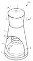
도 2는 본 발명의 일 실시예인 드립 커피 제조기의 사시도이다.
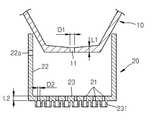
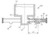
도 3은 도 2에 도시된 드립 커피 제조기의 I-I선 단면도이다.
도 4는 도 3에 도시된 드립 커피 제조기의 II-II선 단면도이다.
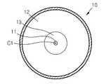
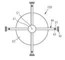
도 5는 도 3에 도시된 드립 커피 제조기의 III-III선 단면도이다.
도 6은 도 3에 도시된 드립 커피 제조기의 IV-IV선 단면도이다.
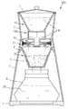
도 7은 도 3에 도시된 드립 커피 제조기의 사용 상태를 설명하기 위한 도면이다.
도 8은 도 3에 도시된 드립 커피 제조기의 제1 용기로부터 배출되는 단위 시간당 유량을 나타내는 그래프이다.
도 9는 도 3에 도시된 드립 커피 제조기의 제2 용기로부터 배출되는 단위 시간당 유량을 나타내는 그래프이다.
도 10은 도 3에 도시된 드립 커피 제조기의 제1 용기 및 제2 용기의 부분확대도이다.
도 11은 본 발명의 다른 실시예인 드립 커피 제조기의 제2 용기를 나타내는 단면도이다.
도 12는 도 11에 도시된 제2 용기의 저면도이다.
도 13은 도 11에 도시된 제2 용기가 장착된 드립 커피 제조기를 나타내는 도면이다.1 is a view for explaining a method of extracting drip coffee using a conventional drip coffee maker.
2 is a perspective view of a drip coffee maker according to an embodiment of the present invention.
FIG. 3 is a II line sectional view of the drip coffee maker shown in FIG. 2. FIG.
Fig. 4 is a sectional view taken along line II-II of the drip coffee maker shown in Fig. 3;
5 is a sectional view taken along line III-III of the drip coffee maker shown in Fig.
6 is a sectional view taken along line IV-IV of the drip coffee maker shown in Fig.
7 is a view for explaining the use state of the drip coffee maker shown in Fig.
8 is a graph showing the flow rate per unit time discharged from the first vessel of the drip coffee maker shown in Fig.
FIG. 9 is a graph showing the flow rate per unit time discharged from the second vessel of the drip coffee maker shown in FIG. 3; FIG.
Figure 10 is a partial enlarged view of the first vessel and the second vessel of the drip coffee maker shown in Figure 3;
11 is a sectional view showing a second container of a drip coffee maker according to another embodiment of the present invention.
12 is a bottom view of the second container shown in Fig.
13 is a view showing a drip coffee maker equipped with the second container shown in Fig.
이하에서, 첨부된 도면들을 참조하여 본 발명의 바람직한 실시예를 상세하게 설명하기로 한다.Hereinafter, preferred embodiments of the present invention will be described in detail with reference to the accompanying drawings.
도 2는 본 발명의 일 실시예인 드립 커피 제조기의 사시도이며, 도 3은 도 2에 도시된 드립 커피 제조기의 I-I선 단면도이다.Fig. 2 is a perspective view of a drip coffee maker according to one embodiment of the present invention, and Fig. 3 is a sectional view taken along the line I-I of the drip coffee maker shown in Fig.
도 2 내지 도 3을 참조하면, 본 발명의 바람직한 실시예에 따른 드립 커피 제조기(100)는, 커피 원두를 잘게 빻은 커피 가루(C)에 물을 부어서 드립 커피를 추출하는 드립 커피 제조기로서, 외부 케이스와, 제1 용기(10)와, 제2 용기(20)와, 제3 용기(30)와, 보온 수단을 포함하여 구성된다.2 to 3, a
상기 외부 케이스는, 투명한 합성수지 재질의 용기로서, 상부 케이스(2)와, 하부 케이스(3)를 포함하여 구성된다.The outer case is made of a transparent synthetic resin material and comprises an upper case (2) and a lower case (3).
상기 상부 케이스(2)는, 상하로 미리 정한 길이만큼 연장된 형상의 원형 파이프형 케이스로서, 세로로 길게 형성된 수직선(C1)을 중심축(C1)으로 가진다.The
상기 상부 케이스(2)의 상단부에는, 상기 상부 케이스(2)의 상단부를 탈착 가능하게 폐쇄할 수 있는 원형의 뚜껑(1)이 장착되어 있다.A
상기 하부 케이스(3)는, 상하로 미리 정한 길이만큼 연장된 형상의 원형 파이프형 케이스로서, 상기 상부 케이스(2)의 하측에 배치되며, 상기 수직선(C1)을 중심축(C1)으로 가진다.The
상기 하부 케이스(3)는, 상단부가 상기 상부 케이스(2)의 하단부에 결합된 상태로 서로 연통되어 있으며, 하단부 측면에는 상기 제3 용기(30)가 출입할 수 있는 용기 수납공(6)이 형성되어 있다.The
상기 하부 케이스(3)의 하단부에는, 상기 하부 케이스(3)의 하단부를 폐쇄하도록 형성된 받침대(4)가 결합되어 있다.A lower end of the
상기 하부 케이스(3)의 상단부 내주면에는, 상기 중심축(C1)의 원주 방향을 따라 둘레의 일부에 형성된 걸림턱(5)이 마련되어 있다. 여기서, 상기 걸림턱(5)은 상기 중심축(C1)을 향하여 돌출된 형상을 가진다.The inner circumference of the upper end of the
상기 제1 용기(10)는, 상기 상부 케이스(2) 내부에 배치된 투명한 합성수지 재질의 용기로서, 상단부가 개구됨으로써 위로부터 부은 물이 수용될 수 있는 용기이다. 이 제1 용기(10)는, 제1 관통공(11)과, 경사부(12)와, 바닥부(13)를 포함하여 구성된다.The
상기 경사부(12)는, 도 3에 도시된 바와 같이 아래 방향(X)인 하단부로 갈수록 내경(R)이 감소하도록 미리 정한 경사각(α)을 가지는 깔때기 형상의 원형 파이프 부분으로서, 세로로 길게 형성된 수직선(C1)을 중심축(C1)으로 가진다.The
상기 경사부(12)는, 상단부가 상기 상부 케이스(2)의 상단부에 결합된 상태로, 상기 상부 케이스(2)의 내부에 수용되어 있다.The
상기 바닥부(13)는, 상기 경사부(12)의 하단부를 폐쇄하도록 형성된 원판 부분으로서, 상기 수직선(C1)을 원의 중심으로 가진다.The
본 실시예에서는 상기 제1 용기(10)가 미리 정한 경사각(α)을 가지는 뒤집힌 원뿔대 형상을 가지게 된다.In this embodiment, the
상기 제1 관통공(11)은, 상기 바닥부(13)의 중심(C1)에 형성된 원형 구멍으로서, 상기 제1 용기(10)에 수용된 물이 아래로 자유 낙하하여 배출되는 통로이다.The first through
상기 경사각(α)은 60도 내지 70도의 값에서 선택될 수 있으며, 상기 제1 용기(10)가 동일한 양의 물을 수용하고 동일한 직경의 상기 바닥부(13)와 제1 관통공(11)을 포함한다고 전제할 때, 상기 경사각(α)이 작아질수록 상기 제1 관통공(11)을 통하여 배출되는 물의 단위 시간당 유량이 증가하게 된다. 본 실시예에서 상기 경사각(α)은 63도의 값을 가진다.The inclination angle alpha may be selected from a value between 60 degrees and 70 degrees, and the
여기서, 상기 제1 관통공(11)을 통하여 배출되는 단위 시간당 유량(q1)은, 상기 제1 관통공(11)의 직경과 상기 제1 용기(10) 내에 수용된 물의 수위에 비례하게 된다.The flow rate q1 per unit time discharged through the first through
상기 제1 용기(10)는, 도 10에 도시된 바와 같이 상기 제1 관통공(11)의 직경(D1)이 1.4 내지 1.9mm이며, 상기 제1 관통공(11)의 길이(L1)은 1.0 내지 2.0mm이다.10, the diameter D1 of the first through
본 실시예에서 상기 제1 용기(10)는, 상기 제1 관통공(11)의 직경(D1)이 1.6mm이며, 160 내지 500ml의 물을 수용할 수 있는 크기의 용기이다.In the present embodiment, the
상기 제2 용기(20)는, 상기 제1 용기(10)와 마찬가지로 투명한 합성수지 재질의 용기로서, 상기 외부 케이스(2,3)의 내부에 배치되어 있으며, 상기 제1 용기(10)의 하측에 배치됨으로써 상기 제1 관통공(11)으로부터 배출되는 물이 임시로 수용되는 용기이다. 이 제2 용기(20)는, 제2 관통공(21)과, 측면부(22)와, 바닥부(23)를 포함하여 구성된다.The
상기 측면부(22)는, 상하로 미리 정한 길이만큼 연장된 형상의 원형 파이프 부분으로서, 상기 수직선(C1)을 중심축(C1)으로 가진다.The
상기 측면부(22)의 상단부는 상기 제1 용기(10)의 경사부(12) 외주면에 결합되어 있다.The upper end of the
상기 측면부(22)의 상단부 측면에는, 상기 제2 용기(20)의 내부에 수용된 물이 상기 제2 관통공(21)을 통하여 원활하게 배출될 수 있도록, 외부 공기가 유입되는 통기구(22a)가 형성되어 있다.A
상기 바닥부(23)는, 상기 측면부(22)의 하단부를 폐쇄하도록 형성된 원판 부분으로서, 상기 수직선(C1)을 원의 중심으로 가진다.The
상기 제2 관통공(21)은, 상기 바닥부(23)에 형성된 복수 개의 원형 구멍으로서, 상기 제2 용기(20)에 수용된 물이 아래로 자유 낙하하여 배출되는 통로이다. 본 실시예에서는 상기 제2 관통공(21)이 14개 형성되어 있다.The second through
상기 바닥부(23)의 하면에는, 원형의 파이프 부재인 가이드 부재(231)가 복수 개 마련되어, 수밀 가능하게 결합되어 있다.A plurality of
상기 가이드 부재(231)의 일단부는, 상기 제2 관통공(21)의 주변을 둘러싸도록 배치되어 있다.One end of the
상기 가이드 부재(231)의 타단부는, 상기 바닥부(23)의 하면으로부터 미리 정한 길이만큼 돌출되어 있다.The other end of the
상기 가이드 부재(231)에 의하여, 상기 제2 관통공(21)으로부터 배출되는 물이 상기 바닥부(23)의 표면을 따라 좌우로 흘러 이동하는 것을 방지하고, 정확한 위치에 하방으로 낙하할 수 있도록 안내될 수 있다.The
여기서, 상기 제2 관통공(21)을 통하여 배출되는 단위 시간당 유량(q2)은, 상기 제2 관통공(21)의 직경과 상기 제2 용기(20) 내에 수용된 물의 수위에 비례하게 된다.Here, the flow rate q2 per unit time discharged through the second through
상기 제2 용기(20)에 수용되어 있는 물이, 표면장력과 점성에 의하여 상기 제2 관통공(21)을 통하여 미리 정한 단위 시간당 유량(q2)으로 서서히 배출될 수 있도록, 도 10에 도시된 바와 같이 상기 제2 관통공(21)의 직경(D2)이 0.4 내지 0.9mm이며, 상기 제2 관통공(21)의 길이(L2)는 1.0 내지 2.0mm이다.In order that the water contained in the
본 실시예에서 상기 제2 용기(20)는, 상기 관통공(21)의 직경(D2)이 0.5mm이며, 상기 제2 관통공(21)의 길이(L2)는 1.4mm이며, 20 내지 60ml의 물을 수용할 수 있는 크기의 용기이다.
The diameter D2 of the through
한편, 상기 제1 관통공(11) 및 제2 관통공(21)의 직경 및 길이는 아래의 표 1 내지 표 4의 실험 자료를 근거로 결정되었다. 여기서, 상기 제1 용기(10)의 내부로 물(W) 250ml를 붓는 것을 전제로 한다.
The diameters and lengths of the first through
시간(time(secsec))
상기 표 1에서 알 수 있듯이, 상기 제2 용기(20)에 수용된 물이 모두 배출되는 시간이 150초 내지 180초가 되는 경우는, 상기 제1 용기(10)의 직경(D1)이 1.8mm 또는 2.0mm의 경우이지만, 90초 지점의 상기 제2 용기(20)의 수위가 각각 79mm, 93mm로 너무 높아서 적절하지 않다. 따라서, 제2 관통공(21)의 직경(D2)은 0.4mm보다 클 것이 요구된다. 여기서, 상기 제2 용기(20)의 수위는 상기 제2 관통공(21)을 통과하는 물의 수압과 비례하게 된다.
As can be seen from Table 1, when the time for discharging the water contained in the
시간time
상기 표 2에서 알 수 있듯이, 상기 제2 용기(20)에 수용된 물이 모두 배출되는 시간이 150초 내지 180초가 되는 경우는, 상기 제1 용기(10)의 직경(D1)이 1.6mm 또는 1.8mm의 경우로서, 70초 지점의 상기 제2 용기(20)의 수위가 각각 43mm, 42mm로 적절한 값을 가진다.
As can be seen from Table 2, when the time for discharging all the water contained in the
시간time
상기 표 3에서 알 수 있듯이, 상기 제2 용기(20)에 수용된 물이 모두 배출되는 시간이 150초 내지 180초가 되는 경우는, 상기 제1 용기(10)의 직경(D1)이 1.6mm 또는 1.8mm의 경우로서, 70초 지점의 상기 제2 용기(20)의 수위가 각각 33mm, 45mm로 적절한 값을 가진다.
As can be seen from Table 3, when the time taken for the water contained in the
시간time
상기 표 4에서 알 수 있듯이, 상기 제2 용기(20)에 수용된 물이 모두 배출되는 시간이 150초 내지 180초가 되는 경우는, 상기 제1 용기(10)의 직경(D1)이 1.6mm의 경우로서, 70초 지점의 상기 제2 용기(20)의 수위가 각각 26mm로 적절한 값을 가진다. 상기 제1 용기(10)의 직경(D1)이 다른 값을 가지는 경우는 상기 제2 용기(20)의 수위가 너무 크거나 작다.
As can be seen from Table 4, when the time taken for the water contained in the
시간time
상기 표 5에서 알 수 있듯이, 상기 제2 용기(20)에 수용된 물이 모두 배출되는 시간이 150초 내지 180초가 되는 경우는, 상기 제1 용기(10)의 직경(D1)이 1.4mm 또는 1.6mm의 경우로서, 70초 지점의 상기 제2 용기(20)의 수위가 각각 12mm, 23mm의 값을 가진다. 상기 제1 용기(10)의 직경(D1)이 다른 값을 가지는 경우는 상기 제2 용기(20)의 수위가 너무 크다.
As can be seen from Table 5, when the time taken for the water contained in the
시간time
상기 표 6에서 알 수 있듯이, 상기 제2 용기(20)에 수용된 물이 모두 배출되는 시간이 150초 내지 180초가 되는 경우는 없으며, 상기 제1 용기(10)의 직경(D1)이 1.6mm의 경우에, 70초 지점의 상기 제2 용기(20)의 수위가 각각 8mm의 값을 가지며, 상기 제2 용기(20)에 수용된 물이 모두 배출되는 시간이 130초로 최대치이다. 상기 제1 용기(10)의 직경(D1)이 다른 값을 가지는 경우는 상기 제2 용기(20)에 수용된 물이 모두 배출되는 시간이 너무 짧다.
As can be seen from Table 6, the time for discharging all of the water contained in the
상기 제2 관통공(21)은, 도 5에 도시된 바와 같이 상기 제1 관통공(11)으로부터 하방으로 수직하게 연장된 가상의 수직선(C1) 상에 있지 아니하며, 상기 제1 용기(10)의 수직선(C1)을 중심으로 하는 복수 개의 동심원(P) 상에 배치되어 있다.The second through
본 실시예에서, 상기 제2 관통공(21) 중의 일부는 최내측에 위치한 동심원(P) 상의 가상의 마름모 꼭지점에 각각 위치하며, 상기 제2 관통공(21) 중의 또 다른 일부는 중간에 위치한 동심원(P) 상의 가상의 오각형 꼭지점에 각각 위치하며, 상기 제2 관통공(21) 중의 나머지는 최외측에 위치한 동심원(P) 상의 가상의 역오각형 꼭지점에 각각 위치한다.In this embodiment, some of the second through
따라서, 상기 제1 용기(10)의 제1 관통공(11)을 통하여 자유 낙하하는 물이, 상기 제2 용기(20)의 내부에 머무르지 않고 곧바로 상기 제2 관통공(21)을 관통하지 못하는 구조를 가진다.Therefore, water falling freely through the first through-
상기 제3 용기(30)는, 상기 커피 가루(C)와 상기 제2 관통공(21)으로부터 배출되는 물을 수용하는 용기로서, 상기 하부 케이스(3)의 내부에 배치되어 있으며, 상기 제1 용기(10)와 마찬가지로 상단부가 개구된 투명한 합성수지 재질의 용기이다. 이 제3 용기(30)는, 제3 관통공(31)과, 측면부(32)와, 바닥부(33)와, 걸림부(34)를 포함하여 구성된다.The
상기 측면부(32)는, 아래 방향(X)인 하단부로 갈수록 내경이 감소하도록 형성된 깔때기 형상의 원형 파이프 부분으로서, 상기 수직선(C1)을 중심축(C1)으로 가지며, 상기 제2 용기(20)의 하측에 배치되어 있다.The
상기 바닥부(33)는, 상기 측면부(32)의 하단부를 폐쇄하도록 형성된 원판 부분으로서, 상기 수직선(C1)을 원의 중심으로 가진다.The
상기 제3 관통공(31)은, 상기 바닥부(33)의 중심(C1)에 형성된 복수 개의 원형 구멍으로서, 상기 제3 용기(30)내에서 추출된 드립 커피(DC)가 아래로 자유 낙하하여 배출되는 통로이다.The third through
상기 걸림부(34)는, 상기 측면부(32)의 상단부 외주면에 형성된 돌출부로서, 상기 중심축(C1)의 원주 방향을 따라 둘레의 일부에 형성되어 있으며, 도 3에 도시된 바와 같이 상기 하부 케이스(3)에 형성된 걸림턱(5)에 의하여 받쳐서 지지된다.The engaging
상기 걸림부(34)는, 상기 중심축(C1)의 반경 방향으로 돌출되어 있으며, 상기 하부 케이스(3)에 형성된 걸림턱(5)과 탈착 가능하게 결합될 수 있는 부분이다.The engaging
여기서, 상기 걸림부(34)와 걸림턱(5)의 결합 구조는 당업자에게 널리 알려진 기술 사항인 바 상세한 설명은 생략하기로 한다. 예컨대, 상기 제3 용기(30)를 상기 중심축(C1)을 따라 상방으로 밀어 올린 상태에서 상기 중심축(C1)을 중심으로 약간 회전시킴으로써, 상기 걸림부(34)와 걸림턱(5)을 탈착 가능하게 결합시키는 구조 등이 사용될 수 있다.Here, the coupling structure of the latching
상기 보온 수단은, 상기 제1 용기(10)와 제2 용기(20) 및 제3 용기(30)를 보온하기 위한 수단이다.The heat keeping means is means for keeping the
본 실시예에서는, 상기 보온 수단이 상기 뚜껑(1)과 상기 상부 케이스(2)와 상기 하부 케이스(3)와 상기 받침대(4)를 포함하여 구성된다.In this embodiment, the heating means includes the
이하에서는, 상술한 구성의 드립 커피 제조기(100)를 사용하는 방법의 일례를 설명하기로 한다.Hereinafter, an example of a method of using the
먼저, 도 7에 도시된 바와 같이 상기 제3 용기(30)에 종이로 된 필터(F)를 깔고 그 필터(F) 위에 15g의 커피 가루(C)를 넣은 후, 상기 용기 수납공(6)을 통하여 상기 제3 용기(30)의 걸림부(34)를 상기 하부 케이스(3)의 걸림턱(5)에 탈착 가능하게 결합시킨다.7, a paper filter F is laid on the
이어서, 상기 제3 용기(30)의 하방에 위치한 상기 받침대(4) 위에, 추출된 드립 커피(DC)가 수용될 커피 용기(B)를 위치시킨 후, 상기 뚜껑(1)을 열고 상기 제1 용기(10)의 내부로 뜨거운 물(W) 250ml를 붓는다.Subsequently, after the coffee container B in which the extracted drip coffee DC is to be placed is placed on the
본 실시예에서, 상기 제1 용기(10)에 수용된 물은 도 8에 도시된 바와 같이 t=T4에서 모두 배출된다. 여기서, 상기 T4의 값은 140초이다.In this embodiment, the water contained in the
이렇게 상기 제1 용기(10)에 수용된 물(W)은 상기 제1 관통공(11)을 통하여 아래로 자유 낙하하게 되고, 상기 제2 용기(20)의 내부에 임시로 수용된다.Thus, the water W contained in the
여기서, 도 8에 도시된 바와 같이 상기 제1 관통공(11)으로부터 배출되는 단위 시간당 유량(q1)은, 시간(t)이 경과되면서 상기 제1 용기(10) 내부의 수위가 감소됨에 따라 계속 감소하게 된다.Here, as shown in FIG. 8, the flow rate q1 per unit time discharged from the first through
이어서, 상기 제2 용기(20)의 내부에 임시로 수용된 물(W)은 상기 제2 관통공(21)을 통하여 아래로 자유 낙하하게 되고, 상기 제3 용기(30)의 내부에 수용된 커피 가루(C) 위에 떨어지게 된다.The water W temporarily accommodated in the
여기서, 도 9에 도시된 바와 같이, 상기 제1 관통공(11)으로부터 배출되는 단위 시간당 유량(q1)이 처음에는 상기 제2 관통공(21)으로부터 배출되는 단위 시간당 유량(q2)보다 크지만, 시간(t)이 경과하면서 상기 제1 관통공(11)으로부터 배출되는 단위 시간당 유량(q1)은 서서히 감소하게 되어 상기 제2 관통공(21)으로부터 배출되는 단위 시간당 유량(q2)과 같아진 후, 나중에는 상기 제2 관통공(21)으로부터 배출되는 단위 시간당 유량(q2)보다 작아지게 된다.9, the flow rate q1 per unit time discharged from the first through
따라서, 도 9에 도시된 바와 같이 상기 제2 관통공(21)으로부터 배출되는 단위 시간당 유량(q2)은, t=T1까지의 초기에는 서서히 증가하다가, 시간(t)이 경과하면서 t=T1부터 t=T2까지의 중기에는 미리 정한 값으로 일정하게 유지되며, t=T2부터 t=T3까지의 후기에는 다시 서서히 감소하여 "0"이 된다. 본 실시예에서는 상기 T3의 값이 160초이다.Therefore, as shown in FIG. 9, the flow rate q2 per unit time discharged from the second through
상기 제2 관통공(21)으로부터 배출되는 물은, 초기(0 ≤ t ≤T1)에는 상기 제3 용기(30)의 내부에 수용된 커피 가루(C)를 미리 가볍게 적셔주는 뜸들이기 기능을 하게 되고, 중기(T1 ≤ t ≤T2)에는 미리 적셔진 커피 가루(C)로부터 본격적인 커피 추출을 하게 되며, 후기(T2 ≤ t ≤T3)에는 서서히 유량이 감소하면서, 대략 3분 이내의 시간 동안 약 230ml의 드립 커피(DC)의 추출을 마무리하게 된다.The water discharged from the second through
이렇게, 드립 커피(DC)를 3분 정도에 추출을 마쳐야하는 이유는, 커피 추출 시간이 3분을 초과할 경우, 커피 가루(C)의 세포벽 성분 등이 녹아내림으로써, 커피 고유의 쓴맛, 신맛, 단맛 등을 느끼게 하는 유용한 성분 이외에 불쾌한 쓴맛이나 향 등을 느끼게 하는 나쁜 성분이 추출될 수 있기 때문이다.The reason why the drip coffee (DC) should be extracted in about 3 minutes is because when the coffee extraction time exceeds 3 minutes, the cell wall component of the coffee powder (C) melts down, , And a bad component that makes the user feel uncomfortable bitter taste and incense in addition to a useful ingredient which makes the user feel the sweetness and the like can be extracted.
상술한 구성의 드립 커피 제조기(100)는, 물을 수용하는 용기로서 물이 아래로 배출될 수 있도록 하단부에 제1 관통공(11)을 구비하는 제1 용기(10)와, 상기 제1 관통공(11)으로부터 배출되는 물을 수용하는 용기로서 상기 제1 용기(10)의 하측에 배치되며 내부에 수용된 물(W)이 상기 커피 가루(C) 위로 배출될 수 있도록 하단부에 복수 개의 제2 관통공(21)을 구비하는 제2 용기(20)를 포함하며, 상기 제1 관통공(11)의 직경(D1)은 1.4 내지 1.9mm이며, 상기 제2 관통공(21)의 직경(D2)은 0.4 내지 0.9mm이며, 상기 제2 용기(20)에 수용되어 있는 물(W)은, 물의 표면장력과 점성에 의하여 상기 제2 관통공(21)을 통하여 미리 정한 단위 시간당 유량(q2)으로 서서히 배출되므로, 일종의 버퍼(buffer) 기능을 수행하는 상기 제2 용기(20) 및 상기 제2 관통공(21)의 미세한 직경(D2)으로 인한 표면장력과 점성에 의하여, 상기 커피 가루(C) 위의 넓은 영역에 비교적 작은 값의 단위 시간당 유량(q2)으로 물을 서서히 뿌려줄 수 있다는 장점이 있다.The
그리고, 상기 드립 커피 제조기(100)는, 상기 커피 가루(C)와 상기 제2 관통공(21)으로부터 배출되는 물을 수용하는 용기로서 상기 제2 용기(20)의 하측에 배치되며, 추출된 드립 커피(DC)가 아래로 배출될 수 있도록 하단부에 제3 관통공(31)을 구비하는 제3 용기(30)를 포함하고 있으므로, 상기 제2 용기(20)로부터 자유 낙하하는 물을 직접 상기 제3 용기(30)에 수용하여 드립 커피(DC)를 추출할 수 있는 장점이 있다.The
또한, 상기 드립 커피 제조기(100)는, 상기 제1 용기(10)가, 하단부로 갈수록 내경(R)이 감소하도록, 미리 정한 경사각(α)을 가지는 깔때기 형상이므로, 상기 제1 용기(10)의 내부에 수용된 물의 수위가 시간(t)에 따라 미리 정한 속도로 감소될 수 있는 장점이 있다.The
그리고, 상기 드립 커피 제조기(100)는, 상기 제1 용기(10)가 상기 경사각(α)이 60도 내지 70도이므로, 상기 제1 용기(10)의 내부에 수용되는 물의 부피와 상기 제1 관통공(11)의 직경을 고려하여 상기 경사각(α)을 선택함으로써, 상기 단위 시간당 유량(q1)을 용이하게 조절할 수 있는 장점이 있다.In the
또한, 상기 드립 커피 제조기(100)는, 상기 제1 용기(10)가, 미리 정한 경사각(α)을 가지는 뒤집힌 원뿔대 형상이며, 상기 제1 관통공(11)이 상기 원뿔대의 중심축(C1) 상에 배치되어 있으므로, 상기 제1 용기(10)의 내부에 수용된 물이 상기 제1 관통공(11)을 통하여 급격하게 배출되지 않고 서서히 배출될 수 있으며, 상기 제1 용기(10)의 내부에 수용된 물이 남김없이 모두 배출될 수 있는 장점이 있다.The
그리고, 상기 드립 커피 제조기(100)는, 상기 제2 관통공(21)이 상기 제1 관통공(11)으로부터 하방으로 수직하게 연장된 가상의 수직선(C1) 위에 있지 아니하므로, 상기 제1 관통공(11)을 통하여 자유 낙하하는 물이 곧바로 상기 제2 관통공(21)을 관통하지 못함으로써, 상기 제2 용기(20)의 내부에 좀 더 오랫동안 머무를 수 있는 장점이 있다.Since the second through
또한, 상기 드립 커피 제조기(100)는, 상기 제2 관통공(21)이 상기 원뿔대의 중심축(C1)을 중심으로 하는 복수 개의 동심원(P) 상에 배치되어 있으므로, 상기 제3 용기(30)의 내부에 수납된 커피 가루(C) 위의 넓은 영역에 물을 골고루 뿌려줄 수 있다는 장점이 있다.Since the second through
그리고, 상기 드립 커피 제조기(100)는, 상기 제1 용기(10)와 제2 용기(20) 및 제3 용기(30)를 보온하기 위한 보온 수단을 구비하고 있으므로, 상기 제1 용기(10)와 제2 용기(20) 및 제3 용기(30)의 내부에 수용된 물의 온도를 비교적 장시간 유지할 수 있는 장점이 있다.The
또한, 상기 드립 커피 제조기(100)는, 상기 제1 용기(10)와 제2 용기(20)와 제3 용기(30)와 상부 케이스(2) 및 하부 케이스(3)가 투명한 재질의 합성수지를 포함하고 있으므로, 내부에 수용된 물의 양을 사용자가 시각적으로 확인할 수 있으며, 장식감이 우수하다는 장점이 있다.The
본 실시예에서는, 상기 제1 용기(10)와 제2 용기(20)와 제3 용기(30)와 상부 케이스(2) 및 하부 케이스(3)가 투명한 재질의 합성수지로 제조되고 있으나, 반투명 재질의 합성수지가 사용될 수도 있음은 물론이다.In the present embodiment, the
본 실시예에서는, 상기 제1 용기(10)가 미리 정한 경사각(α)을 가지는 뒤집힌 원뿔대 형상을 가지고 있으나, 상기 제1 용기(10)가 미리 정한 경사각(α)을 가지는 뒤집힌 원뿔 형상을 가질 수도 있음은 물론이다.In the present embodiment, the
본 실시예에서는, 상기 용기 수납공(6)이 개방되어 있으나, 상기 용기 수납공(6)을 개방시키는 개방 위치와 폐쇄하는 폐쇄 위치 사이에서 위치 이동 가능한 도어가 장착될 수도 있음은 물론이다.It is needless to say that the container
한편, 도 13에는 본 발명의 다른 실시예인 드립 커피 제조기(200)가 도시되어 있다. 이 드립 커피 제조기(200)는 대부분의 구성이 상기 드립 커피 제조기(100)와 동일하므로, 그에 대한 설명은 생략하고 양자 간의 차이점에 대해서만 설명하기로 한다.13 shows a
상기 드립 커피 제조기(200)는, 도 11에 도시된 바와 같은 제2 용기(120)를 포함하고 있다. 상기 제2 용기(120)는, 상기 드립 커피 제조기(100)의 제2 용기(20)와 대부분의 구성이 동일하므로, 이하에서는 그 차이점에 대해서만 설명하기로 한다. 이 제2 용기(120)는, 허브(24)와, 분기관(40)을 포함한다.The
상기 허브(24)는, 상기 중심축(C1)을 원의 중심으로 하는 원통형 용기로서, 상기 바닥부(23)로부터 하방으로 돌출되어 있으며, 상기 측면부(22)와 연통되어 내부에 물이 수용되어 있다.The
상기 분기관(40)은, 복수 개 마련되며, 미리 정한 내경(D3)을 가지는 원형 파이프 형상의 부재로서, 미리 정한 길이 만큼 길게 연장되어 있다.A plurality of branch pipes (40) are provided and are circular pipe-shaped members having a predetermined inner diameter (D3), and are elongated by a predetermined length.
상기 분기관(40)은, 도 11 및 도 12에 도시된 바와 같이 상기 측면부(22)의 중심축(C1)을 중심으로 반경 방향으로 수평하게 연장되어 있으며, 상기 측면부(22)의 중심축(C1)을 중심으로 방사상으로 4개가 배치되어 있다.11 and 12, the
상기 분기관(40)은, 일단부가 상기 허브(24)의 외주면에 결합됨으로써, 상기 허브(24)의 내부에 수용된 물이 유입될 수 있는 구조이다.One end of the
상기 분기관(40)의 타단부 하면에는, 미리 정한 길이(L2)를 가지는 상기 제2 관통공(21)이 형성되어 있다.
The second through hole (21) having a predetermined length (L2) is formed on the other end surface of the branch pipe (40).
*상기 제2 관통공(21)은, 상기 허브(24)의 외주면으로부터 반경 방향으로 미리 정한 거리(L3)만큼 이격된 지점에 형성되어 있다.The second through
상기 분기관(40)의 내부로 흐르는 물이 표면장력과 점성에 의하여 유속이 감소하도록, 상기 분기관(40)의 내경(D3) 및 상기 거리(L3)가 결정되는데, 본 실시예에서 상기 분기관(40)의 최소내경(D3)은 1.0 내지 1.5mm이며, 상기 거리(L3)는 상기 제2 관통공(21)이 상기 측면부(22)의 외주면보다 외측에 위치하도록 결정된다.The inner diameter D3 and the distance L3 of the
상기 분기관(40)은, 일단부에서 최대내경(D4)를 가지며, 반경 방향으로 갈수록 내경이 점점 감소하여 상기 최소내경(D3)을 가지는 테이퍼형 내부 구조를 가진다. 여기서, 본 실시예에서 상기 최대내경(D4)은 3.0 내지 4.0mm이다.The branch pipe (40) has a maximum inner diameter (D4) at one end and an inner diameter gradually decreases toward the radial direction to have a tapered inner structure having the minimum inner diameter (D3). In this embodiment, the maximum inner diameter D4 is 3.0 to 4.0 mm.
상기 분기관(40)의 테이퍼형 내부 구조의 구체적 형상이 달라지면, 상기 분기관(40)의 내부를 흐르는 물의 압력 및 유속이 변화하게 된다.When the specific shape of the tapered internal structure of the branch pipe (40) is changed, the pressure and the flow rate of water flowing in the branch pipe (40) are changed.
상기 분기관(40)의 타단부 측면에는, 원형의 나사 구멍인 세정공(41)이 형성되어 있다. 여기서, 상기 세정공(41)은 상기 분기관(40)의 중공(H)과 연통되어 있다.On the other end side surface of the branch pipe (40), a triple hole (41) having a circular screw hole is formed. Here, the
상기 세정공(41)에는, 상기 세정공(41)을 수밀 가능하게 폐쇄하는 수나사 형상의 마개(42)가 착탈 가능하게 나사 결합되어 있다.In the above-mentioned perforation hole (41), a stopper (42) in the form of a male screw, which watertightly closes the perforation hole (41), is removably screwed.
상기 제2 관통공(21)이 형성된 상기 분기관(40)의 하면에는, 원형의 파이프 부재인 가이드 부재(43)의 일단부가 수밀 가능하게 결합되어 있다.One end of a
상기 가이드 부재(43)의 일단부는, 상기 제2 관통공(21)의 주변을 둘러싸도록 배치되어 있다.One end of the guide member (43) is disposed so as to surround the periphery of the second through hole (21).
상기 가이드 부재(43)의 타단부는, 상기 분기관(40)의 하면으로부터 미리 정한 길이만큼 돌출되어 있다.The other end of the
상술한 구성의 드립 커피 제조기(200)는, 상기 제2 용기(120)의 하단부에는, 미리 정한 길이만큼 길게 연장되어 있으며 미리 정한 내경(D3)을 가지는 복수 개의 분기관(40)이 연결되어 있으며, 상기 제2 관통공(21)은 상기 분기관(40)의 말단부에 형성되어 있으므로, 상기 분기관(40)이 없는 경우에 비하여, 상기 제2 관통공(21)을 통하여 배출되는 물의 단위 시간당 유량(q2)을 더욱 감소시킬 수 있으며, 상기 분기관(40)의 내경(D3)이나 길이 조절을 통하여 상기 유량(q2) 조절이 용이하다는 장점이 있다.In the
그리고, 상기 드립 커피 제조기(200)는, 상기 분기관(40)이, 상기 제2 용기(120)의 중심축(C1)을 중심으로 반경 방향으로 수평하게 연장되어 있으며, 복수 개 마련되어 상기 제2 용기(120)의 중심축(C1)을 중심으로 방사상으로 배치되어 있으므로, 상기 분기관(40)의 내부에서 유동하는 물이 중력에 의하여 가속되지 않는 장점이 있으며, 상기 제3 용기(30)의 내부에 수납된 커피 가루(C) 위의 넓은 영역에 물을 골고루 뿌려줄 수 있다는 장점이 있다.The
또한, 상기 드립 커피 제조기(200)는, 상기 분기관(40)의 말단부에 형성되어 있는 구멍인 세정공(41)과, 상기 세정공(41)을 착탈 가능하게 폐쇄하는 마개(42)를 포함하므로, 상기 마개(42)를 분리한 후 상기 세정공(41)을 통하여 상기 분기관(40)의 내부 세정이 편리하다는 장점이 있다.The
그리고, 상기 드립 커피 제조기(200)는, 상기 제2 관통공(21)의 주변을 둘러싸도록 배치되는 관형 부재로서, 상기 분기관(40)의 하면으로부터 미리 정한 길이만큼 돌출되어 있는 가이드 부재(43)를 포함하므로, 상기 제2 관통공(21)으로부터 배출되는 물이 상기 분기관(40)의 외주면을 따라 좌우로 흘러 이동하는 것을 방지하고, 하방으로만 낙하할 수 있도록 안내할 수 있는 장점이 있다.The
이상으로 본 발명을 설명하였는데, 본 발명의 기술적 범위는 상술한 실시예에 기재된 내용으로 한정되는 것은 아니며, 해당 기술 분야의 통상의 지식을 가진 자에 의해 수정 또는 변경된 등가의 구성은 본 발명의 기술적 사상의 범위를 벗어나지 않는 것임은 명백하다.The technical scope of the present invention is not limited to the contents described in the above embodiments, and the equivalent structure modified or changed by those skilled in the art can be applied to the technical It is clear that the present invention does not depart from the scope of thought.
* 도면의 주요부위에 대한 부호의 설명 *
100 : 드립 커피 제조기1 : 뚜껑
2 : 상부 케이스3 : 하부 케이스
4 : 받침대5 : 걸림턱
6 : 용기 수납공10 : 제1 용기
11 : 제1 관통공12 : 경사부
13 : 바닥부20, 120 : 제2 용기
21 : 제2 관통공22 : 측면부
23 : 바닥부24 : 허브
30 : 제3 용기31 : 제3 관통공
32 : 측면부33 : 바닥부
34 : 걸림부40 : 분기관
41 : 세정공42 : 마개
43, 231 : 가이드 부재B : 커피 용기
C : 커피 가루D : 종래의 드립 커피 제조기
D1 : 제1 관통공 직경D2 : 제2 관통공 직경
D3 : 분기관 내경L1 : 제1 관통공 길이
L2 : 제2 관통공 길이F : 필터
K : 주전자R : 내경
C1 : 중심축, 수직선P : 동심원[Description of Reference Numerals]
100: Drip coffee maker 1: lid
2: upper case 3: lower case
4: pedestal 5: hanging jaw
6: container container 10: first container
11: first through hole 12: inclined portion
13: bottom 20, 120: second container
21: second through hole 22: side surface
23: bottom portion 24: hub
30: third container 31: third through hole
32: side portion 33: bottom portion
34: latching portion 40: branching tube
41: Three holes 42: Plug
43, 231: guide member B: coffee container
C: Coffee powder D: Conventional drip coffee maker
D1: First through hole diameter D2: Second through hole diameter
D3: branch pipe inner diameter L1: first through hole length
L2: second through hole length F: filter
K: kettle R: inner diameter
C1: center axis, vertical line P: concentric circle
Claims (9)
Translated fromKorean물을 수용하는 용기로서, 물이 아래로 배출될 수 있도록 하단부에 제1 관통공을 구비하는 제1 용기;
상기 제1 관통공으로부터 배출되는 물을 수용하는 용기로서, 상기 제1 용기의 하측에 배치되며, 내부에 수용된 물이 상기 커피 가루 위로 배출될 수 있도록 하단부에 복수 개의 제2 관통공을 구비하는 제2 용기;
상기 커피 가루와 상기 제2 관통공으로부터 배출되는 물을 수용하는 용기로서, 상기 제2 용기의 하측에 배치되며, 추출된 드립 커피가 아래로 배출될 수 있도록 하단부에 제3 관통공을 구비하는 제3 용기;
를 포함하며,
상기 제1 용기는, 하단부로 갈수록 내경이 감소하도록 미리 정한 경사각을 가지는 깔때기 형상으로서, 미리 정한 경사각을 가지는 뒤집힌 원뿔 또는 원뿔대 형상이며, 상기 제1 관통공이 상기 원뿔 또는 원뿔대의 중심축 상에 배치되어 있으며,
상기 제1 관통공의 직경은 1.4 내지 1.9mm이며, 상기 제2 관통공의 직경은 0.4 내지 0.9mm이며,
상기 제2 용기에 수용되어 있는 물은, 물의 표면장력과 점성에 의하여 상기 제2 관통공을 통하여 미리 정한 단위 시간당 유량으로 서서히 배출되며,
상기 제2 관통공의 주변을 둘러싸도록 배치되는 관형 부재로서, 상기 제2 용기의 하면으로부터 미리 정한 길이만큼 돌출되어 있는 가이드 부재를 포함하는 것을 특징으로 하는 드립 커피 제조기A drip coffee maker for producing drip coffee by pouring water into a finely ground coffee ground coffee bean,
1. A container for receiving water, comprising: a first container having a first through hole at a lower end thereof so that water can be discharged downward;
And a plurality of second through holes disposed at a lower end of the container to allow water contained therein to be discharged onto the coffee ground, 2 containers;
A container for receiving water discharged from the coffee powder and the second through hole, the container being disposed below the second container and having a third through hole at a lower end thereof so that the extracted drip coffee can be discharged downward; 3 containers;
/ RTI >
Wherein the first container has an inverted cone or truncated cone shape having a predetermined inclination angle and having a predetermined inclination angle so that the inner diameter decreases toward the lower end thereof and the first through hole is disposed on the central axis of the cone or truncated cone In addition,
The diameter of the first through hole is 1.4 to 1.9 mm, the diameter of the second through hole is 0.4 to 0.9 mm,
The water contained in the second container is gradually discharged through the second through hole at a flow rate per unit time predetermined by the surface tension and viscosity of the water,
And a guide member protruding from the lower surface of the second container by a predetermined length. The drip coffee maker according to claim 1,
상기 제1 용기는 160 내지 500ml의 물을 수용할 수 있는 크기의 용기이며,
상기 제2 용기는 20 내지 60ml의 물을 수용할 수 있는 크기의 용기인 것을 특징으로 하는 드립 커피 제조기The method according to claim 1,
The first container is a container sized to receive 160 to 500 ml of water,
Wherein the second container is a container sized to accommodate 20 to 60 ml of water.
상기 제1 용기는 상기 경사각이 60도 내지 70도인 것을 특징으로 하는 드립 커피 제조기The method according to claim 1,
Wherein the first container has the inclination angle of 60 to 70 degrees.
상기 제2 용기는,
상기 제2 관통공이 상기 제1 관통공으로부터 하방으로 수직하게 연장된 가상의 수직선 위에 있지 아니한 것을 특징으로 하는 드립 커피 제조기The method according to claim 1,
Wherein the second container comprises:
Wherein the second through-hole is not on a virtual vertical line extending vertically downward from the first through-hole.
상기 제2 용기는,
상기 제2 관통공이 상기 원뿔 또는 원뿔대의 중심축을 중심으로 하는 복수 개의 동심원 상에 배치되어 있는 것을 특징으로 하는 드립 커피 제조기The method according to claim 1,
Wherein the second container comprises:
And the second through-hole is arranged on a plurality of concentric circles centered on the central axis of the cone or truncated cone.
상기 제1 용기와 상기 제2 용기 중 적어도 하나를 보온하기 위한 보온 수단을 포함하는 것을 특징으로 하는 드립 커피 제조기The method according to claim 1,
And a keeping means for keeping at least one of the first container and the second container warm.
상기 제1 용기와 상기 제2 용기 중 적어도 하나는 투명 또는 반투명 재질의 합성수지를 포함하는 것을 특징으로 하는 드립 커피 제조기The method according to claim 1,
Characterized in that at least one of the first container and the second container comprises a transparent or translucent synthetic resin.
상기 제2 관통공의 길이는 1 내지 2mm인 것을 특징으로 하는 드립 커피 제조기The method according to claim 1,
And the length of the second through hole is 1 to 2 mm.
Applications Claiming Priority (2)
| Application Number | Priority Date | Filing Date | Title |
|---|---|---|---|
| KR20130047703 | 2013-04-29 | ||
| KR1020130047703 | 2013-04-29 |
Related Parent Applications (1)
| Application Number | Title | Priority Date | Filing Date |
|---|---|---|---|
| KR1020130137892ADivisionKR101454740B1 (en) | 2013-04-29 | 2013-11-13 | Machine for drip coffee including branch pipes |
Publications (2)
| Publication Number | Publication Date |
|---|---|
| KR20140128897A KR20140128897A (en) | 2014-11-06 |
| KR101494430B1true KR101494430B1 (en) | 2015-02-23 |
Family
ID=51998762
Family Applications (4)
| Application Number | Title | Priority Date | Filing Date |
|---|---|---|---|
| KR1020130137892AExpired - Fee RelatedKR101454740B1 (en) | 2013-04-29 | 2013-11-13 | Machine for drip coffee including branch pipes |
| KR1020140050932AExpired - Fee RelatedKR101632421B1 (en) | 2013-04-29 | 2014-04-28 | Machine for drip coffee |
| KR20140052698AActiveKR101494430B1 (en) | 2013-04-29 | 2014-04-30 | Machine for drip coffee |
| KR1020150069441AActiveKR101623576B1 (en) | 2013-04-29 | 2015-05-19 | Machine for drip coffee |
Family Applications Before (2)
| Application Number | Title | Priority Date | Filing Date |
|---|---|---|---|
| KR1020130137892AExpired - Fee RelatedKR101454740B1 (en) | 2013-04-29 | 2013-11-13 | Machine for drip coffee including branch pipes |
| KR1020140050932AExpired - Fee RelatedKR101632421B1 (en) | 2013-04-29 | 2014-04-28 | Machine for drip coffee |
Family Applications After (1)
| Application Number | Title | Priority Date | Filing Date |
|---|---|---|---|
| KR1020150069441AActiveKR101623576B1 (en) | 2013-04-29 | 2015-05-19 | Machine for drip coffee |
Country Status (4)
| Country | Link |
|---|---|
| US (1) | US20160058240A1 (en) |
| JP (1) | JP2016521170A (en) |
| KR (4) | KR101454740B1 (en) |
| CN (1) | CN205234284U (en) |
Cited By (1)
| Publication number | Priority date | Publication date | Assignee | Title |
|---|---|---|---|---|
| KR20200025149A (en) | 2018-08-29 | 2020-03-10 | 박혜정 | Extracting apparatus for hand-drip coffee |
Families Citing this family (15)
| Publication number | Priority date | Publication date | Assignee | Title |
|---|---|---|---|---|
| GB2530520A (en)* | 2014-09-24 | 2016-03-30 | Sean Martin Moran | A sprayhead for a coffee brewing machine |
| ES2933111T3 (en)* | 2016-11-02 | 2023-02-02 | Nestle Sa | Flow-optimized pour-over coffee brewing system |
| KR101824522B1 (en)* | 2017-01-16 | 2018-02-01 | 이지현 | Water Supplying Device for Coffee Extraction Using Vacuum Pressure |
| KR200486683Y1 (en)* | 2017-07-10 | 2018-06-21 | 주식회사 로스팅 파크 커피 컴퍼니 | Drip coffee machine |
| KR102027651B1 (en)* | 2017-10-18 | 2019-10-01 | 이인두 | The concentrator for health supplementary food |
| KR101892487B1 (en) | 2017-11-20 | 2018-08-31 | 이지현 | Water Supplying Device for Coffee Extraction Using Vacuum Pressure |
| WO2019098749A1 (en)* | 2017-11-20 | 2019-05-23 | 정윤진 | Device for supplying water for coffee extraction by using vacuum force |
| TWI689269B (en)* | 2018-01-10 | 2020-04-01 | 林永富 | Flow guiding device and brewing device with flow guiding device |
| KR101942286B1 (en) | 2018-01-17 | 2019-01-25 | 정윤진 | Water Supplying Device for Coffee Extraction Using Vacuum Pressure |
| KR102242528B1 (en)* | 2019-05-09 | 2021-04-30 | 유한책임회사 미맥 | Three-Tier Devices for Mannual Drip-brewing of Coffees |
| KR102283676B1 (en)* | 2019-12-17 | 2021-07-29 | 권혁창 | Machine for drip coffee |
| KR102575613B1 (en)* | 2021-11-18 | 2023-09-06 | 박희선 | Coffee dripper water adjustment device |
| KR102481713B1 (en)* | 2022-06-14 | 2022-12-27 | 조종구 | Water providing port for coffee dripper |
| WO2024048957A1 (en)* | 2022-08-30 | 2024-03-07 | 삼성전자 주식회사 | Beverage extraction device |
| JP7672756B1 (en)* | 2024-06-25 | 2025-05-08 | 株式会社美術工芸・結 | Filters, filtration methods |
Citations (3)
| Publication number | Priority date | Publication date | Assignee | Title |
|---|---|---|---|---|
| KR20090075650A (en)* | 2009-06-08 | 2009-07-08 | 안승대 | Drip Coffee & Tea Maker |
| KR101152836B1 (en) | 2009-05-14 | 2012-06-12 | 김명기 | Automatic drip coffee machine |
| KR101288241B1 (en) | 2011-08-31 | 2013-07-26 | 김교전 | Water dispenser for drip coffee |
Family Cites Families (22)
| Publication number | Priority date | Publication date | Assignee | Title |
|---|---|---|---|---|
| US1351410A (en)* | 1918-05-31 | 1920-08-31 | William H Bruning | Coffee-pot |
| US1756725A (en)* | 1929-06-12 | 1930-04-29 | Bordeaux Claude George | Coffeepot |
| US1882247A (en)* | 1931-03-23 | 1932-10-11 | Levings Sherburne Davis | Coffee urn |
| US3333527A (en)* | 1964-12-14 | 1967-08-01 | Vacuum Die Casting Corp | Drip brew maker with delay valve |
| JPS5248956Y2 (en)* | 1975-08-26 | 1977-11-08 | ||
| JPS5435367Y2 (en)* | 1976-05-22 | 1979-10-27 | ||
| US4162041A (en)* | 1976-02-19 | 1979-07-24 | Yamshita & Associates Ltd. | Liquid sprinkling device of composite pipe type |
| JPS57108727U (en)* | 1980-12-25 | 1982-07-05 | ||
| JPS5854021Y2 (en)* | 1981-06-09 | 1983-12-08 | 義 高橋 | coffee extractor |
| DE4130446A1 (en)* | 1991-09-13 | 1993-03-25 | Braun Ag | BREW BEVERAGE MACHINE |
| JP2598819Y2 (en)* | 1993-09-10 | 1999-08-23 | 株式会社カリタ | Coffee extractor |
| JPH10295544A (en)* | 1997-04-25 | 1998-11-10 | Lucky C0Ffee Mach Kk | Iced coffee extracter |
| DE59807893D1 (en)* | 1998-12-31 | 2003-05-15 | Wmf Wuerttemberg Metallwaren | coffee machine |
| US6301961B1 (en)* | 1999-08-26 | 2001-10-16 | Patrick J. Rolfes | Insulated beverage carafe with volume indicator |
| JP2005296598A (en)* | 2004-04-15 | 2005-10-27 | Noriko Kubo | Extractor for hand drip |
| JP2007306973A (en)* | 2006-05-16 | 2007-11-29 | Izumi Products Co | Beverage maker |
| US20070272770A1 (en)* | 2006-05-26 | 2007-11-29 | Water Pik, Inc. | Apparatus and methods for a showerhead bracket with integral showerhead |
| KR100958453B1 (en)* | 2008-01-04 | 2010-05-14 | 안승대 | Drip Coffee & Tea Maker |
| GB2476227B (en)* | 2009-11-12 | 2014-03-12 | Kraft Foods R & D Inc | Accessory for beverage preparation |
| JP6276177B2 (en)* | 2011-07-21 | 2018-02-07 | ピーアイ デザイン アーゲー | Dispensing head for beverage maker |
| KR200464674Y1 (en)* | 2012-04-17 | 2013-01-15 | 윤진희 | coffee drip device |
| KR101246888B1 (en)* | 2013-01-04 | 2013-03-25 | 강정모 | Apparatus to spill water for coffee dripper |
- 2013
- 2013-11-13KRKR1020130137892Apatent/KR101454740B1/ennot_activeExpired - Fee Related
- 2014
- 2014-04-28KRKR1020140050932Apatent/KR101632421B1/ennot_activeExpired - Fee Related
- 2014-04-29CNCN201490000621.3Upatent/CN205234284U/ennot_activeExpired - Fee Related
- 2014-04-29JPJP2016511676Apatent/JP2016521170A/enactivePending
- 2014-04-29USUS14/888,056patent/US20160058240A1/ennot_activeAbandoned
- 2014-04-30KRKR20140052698Apatent/KR101494430B1/enactiveActive
- 2015
- 2015-05-19KRKR1020150069441Apatent/KR101623576B1/enactiveActive
Patent Citations (3)
| Publication number | Priority date | Publication date | Assignee | Title |
|---|---|---|---|---|
| KR101152836B1 (en) | 2009-05-14 | 2012-06-12 | 김명기 | Automatic drip coffee machine |
| KR20090075650A (en)* | 2009-06-08 | 2009-07-08 | 안승대 | Drip Coffee & Tea Maker |
| KR101288241B1 (en) | 2011-08-31 | 2013-07-26 | 김교전 | Water dispenser for drip coffee |
Cited By (1)
| Publication number | Priority date | Publication date | Assignee | Title |
|---|---|---|---|---|
| KR20200025149A (en) | 2018-08-29 | 2020-03-10 | 박혜정 | Extracting apparatus for hand-drip coffee |
Also Published As
| Publication number | Publication date |
|---|---|
| KR101454740B1 (en) | 2014-10-27 |
| KR101623576B1 (en) | 2016-05-23 |
| US20160058240A1 (en) | 2016-03-03 |
| KR101632421B1 (en) | 2016-07-01 |
| KR20150059734A (en) | 2015-06-02 |
| KR20140128882A (en) | 2014-11-06 |
| KR20140128897A (en) | 2014-11-06 |
| JP2016521170A (en) | 2016-07-21 |
| CN205234284U (en) | 2016-05-18 |
Similar Documents
| Publication | Publication Date | Title |
|---|---|---|
| KR101494430B1 (en) | Machine for drip coffee | |
| US6276262B1 (en) | System and method of Chinese tea brewing | |
| US4498375A (en) | Automatic coffee pot | |
| EP3087014B1 (en) | Brewable beverage making cup adaptor for cartridge type coffee making machines | |
| ES2792948T3 (en) | Foamer rod | |
| US20160287002A1 (en) | Device for preparing a chilled infused beverage | |
| US4793246A (en) | Electrically operated hot beverage maker | |
| US6422132B1 (en) | Multi-use brew bowl | |
| US20030209152A1 (en) | Hot coffee mixing device for a coffee maker | |
| CN106714628B (en) | Ice drips coffee extracting device and extracting method | |
| KR102283676B1 (en) | Machine for drip coffee | |
| KR101641909B1 (en) | Dutch coffee beans | |
| US20210235917A1 (en) | Beverage preparation devices, apparatus and methods | |
| TWI772236B (en) | Combination of pour over water-guiding cup and pour over device | |
| JP2018198861A (en) | Device for supplying hot water to coffee extracting tool | |
| TWM674286U (en) | Portable coffee filter set structure | |
| TW201641065A (en) | Transparent hand- extraction coffee filter- extraction unit | |
| AU612447B2 (en) | Electrically operated hot beverage maker |
Legal Events
| Date | Code | Title | Description |
|---|---|---|---|
| A107 | Divisional application of patent | ||
| A201 | Request for examination | ||
| PA0107 | Divisional application | St.27 status event code:A-0-1-A10-A16-div-PA0107 St.27 status event code:A-0-1-A10-A18-div-PA0107 | |
| PA0201 | Request for examination | St.27 status event code:A-1-2-D10-D11-exm-PA0201 | |
| E902 | Notification of reason for refusal | ||
| PE0902 | Notice of grounds for rejection | St.27 status event code:A-1-2-D10-D21-exm-PE0902 | |
| E13-X000 | Pre-grant limitation requested | St.27 status event code:A-2-3-E10-E13-lim-X000 | |
| P11-X000 | Amendment of application requested | St.27 status event code:A-2-2-P10-P11-nap-X000 | |
| P13-X000 | Application amended | St.27 status event code:A-2-2-P10-P13-nap-X000 | |
| PG1501 | Laying open of application | St.27 status event code:A-1-1-Q10-Q12-nap-PG1501 | |
| E701 | Decision to grant or registration of patent right | ||
| PE0701 | Decision of registration | St.27 status event code:A-1-2-D10-D22-exm-PE0701 | |
| GRNT | Written decision to grant | ||
| PR0701 | Registration of establishment | St.27 status event code:A-2-4-F10-F11-exm-PR0701 | |
| PR1002 | Payment of registration fee | Fee payment year number:1 St.27 status event code:A-2-2-U10-U11-oth-PR1002 | |
| PG1601 | Publication of registration | St.27 status event code:A-4-4-Q10-Q13-nap-PG1601 | |
| R18-X000 | Changes to party contact information recorded | St.27 status event code:A-5-5-R10-R18-oth-X000 | |
| P22-X000 | Classification modified | St.27 status event code:A-4-4-P10-P22-nap-X000 | |
| PN2301 | Change of applicant | St.27 status event code:A-5-5-R10-R11-asn-PN2301 | |
| P14-X000 | Amendment of ip right document requested | St.27 status event code:A-5-5-P10-P14-nap-X000 | |
| PN2301 | Change of applicant | St.27 status event code:A-5-5-R10-R14-asn-PN2301 | |
| P16-X000 | Ip right document amended | St.27 status event code:A-5-5-P10-P16-nap-X000 | |
| Q16-X000 | A copy of ip right certificate issued | St.27 status event code:A-4-4-Q10-Q16-nap-X000 | |
| P22-X000 | Classification modified | St.27 status event code:A-4-4-P10-P22-nap-X000 | |
| FPAY | Annual fee payment | Payment date:20180502 Year of fee payment:4 | |
| PR1001 | Payment of annual fee | Fee payment year number:4 St.27 status event code:A-4-4-U10-U11-oth-PR1001 | |
| PN2301 | Change of applicant | St.27 status event code:A-5-5-R10-R11-asn-PN2301 St.27 status event code:A-5-5-R10-R13-asn-PN2301 | |
| PN2301 | Change of applicant | St.27 status event code:A-5-5-R10-R11-asn-PN2301 | |
| PN2301 | Change of applicant | St.27 status event code:A-5-5-R10-R11-asn-PN2301 | |
| PN2301 | Change of applicant | St.27 status event code:A-5-5-R10-R14-asn-PN2301 | |
| P14-X000 | Amendment of ip right document requested | St.27 status event code:A-5-5-P10-P14-nap-X000 | |
| FPAY | Annual fee payment | Payment date:20190207 Year of fee payment:5 | |
| PR1001 | Payment of annual fee | Fee payment year number:5 St.27 status event code:A-4-4-U10-U11-oth-PR1001 | |
| PN2301 | Change of applicant | St.27 status event code:A-5-5-R10-R11-asn-PN2301 | |
| PN2301 | Change of applicant | St.27 status event code:A-5-5-R10-R14-asn-PN2301 | |
| PR1001 | Payment of annual fee | Fee payment year number:6 St.27 status event code:A-4-4-U10-U11-oth-PR1001 | |
| PC1903 | Unpaid annual fee | Not in force date:20210212 Payment event data comment text:Termination Category : DEFAULT_OF_REGISTRATION_FEE St.27 status event code:A-4-4-U10-U13-oth-PC1903 | |
| R18-X000 | Changes to party contact information recorded | St.27 status event code:A-5-5-R10-R18-oth-X000 | |
| K11-X000 | Ip right revival requested | St.27 status event code:A-6-4-K10-K11-oth-X000 | |
| PC1903 | Unpaid annual fee | Ip right cessation event data comment text:Termination Category : DEFAULT_OF_REGISTRATION_FEE Not in force date:20210212 St.27 status event code:N-4-6-H10-H13-oth-PC1903 | |
| PR0401 | Registration of restoration | St.27 status event code:A-6-4-K10-K13-oth-PR0401 | |
| R401 | Registration of restoration | ||
| PR1001 | Payment of annual fee | Fee payment year number:7 St.27 status event code:A-4-4-U10-U11-oth-PR1001 | |
| PR1001 | Payment of annual fee | Fee payment year number:8 St.27 status event code:A-4-4-U10-U11-oth-PR1001 | |
| P14-X000 | Amendment of ip right document requested | St.27 status event code:A-5-5-P10-P14-nap-X000 | |
| PN2301 | Change of applicant | St.27 status event code:A-5-5-R10-R11-asn-PN2301 | |
| P16-X000 | Ip right document amended | St.27 status event code:A-5-5-P10-P16-nap-X000 | |
| PN2301 | Change of applicant | St.27 status event code:A-5-5-R10-R14-asn-PN2301 | |
| PR1001 | Payment of annual fee | Fee payment year number:9 St.27 status event code:A-4-4-U10-U11-oth-PR1001 | |
| PR1001 | Payment of annual fee | Fee payment year number:10 St.27 status event code:A-4-4-U10-U11-oth-PR1001 | |
| PR1001 | Payment of annual fee | Fee payment year number:11 St.27 status event code:A-4-4-U10-U11-oth-PR1001 |