KR101493541B1 - Method and apparatus for converting between a multi-sector, omni-base station configuration and a multi-sector base station configuration - Google Patents
Method and apparatus for converting between a multi-sector, omni-base station configuration and a multi-sector base station configurationDownload PDFInfo
- Publication number
- KR101493541B1 KR101493541B1KR1020097023879AKR20097023879AKR101493541B1KR 101493541 B1KR101493541 B1KR 101493541B1KR 1020097023879 AKR1020097023879 AKR 1020097023879AKR 20097023879 AKR20097023879 AKR 20097023879AKR 101493541 B1KR101493541 B1KR 101493541B1
- Authority
- KR
- South Korea
- Prior art keywords
- sector
- base station
- antenna
- frequency
- unit
- Prior art date
- Legal status (The legal status is an assumption and is not a legal conclusion. Google has not performed a legal analysis and makes no representation as to the accuracy of the status listed.)
- Expired - Fee Related
Links
Images


Classifications
- H—ELECTRICITY
- H01—ELECTRIC ELEMENTS
- H01Q—ANTENNAS, i.e. RADIO AERIALS
- H01Q3/00—Arrangements for changing or varying the orientation or the shape of the directional pattern of the waves radiated from an antenna or antenna system
- H01Q3/24—Arrangements for changing or varying the orientation or the shape of the directional pattern of the waves radiated from an antenna or antenna system varying the orientation by switching energy from one active radiating element to another, e.g. for beam switching
- H—ELECTRICITY
- H04—ELECTRIC COMMUNICATION TECHNIQUE
- H04W—WIRELESS COMMUNICATION NETWORKS
- H04W88/00—Devices specially adapted for wireless communication networks, e.g. terminals, base stations or access point devices
- H04W88/08—Access point devices
- H—ELECTRICITY
- H04—ELECTRIC COMMUNICATION TECHNIQUE
- H04W—WIRELESS COMMUNICATION NETWORKS
- H04W16/00—Network planning, e.g. coverage or traffic planning tools; Network deployment, e.g. resource partitioning or cells structures
- H04W16/24—Cell structures
- Y—GENERAL TAGGING OF NEW TECHNOLOGICAL DEVELOPMENTS; GENERAL TAGGING OF CROSS-SECTIONAL TECHNOLOGIES SPANNING OVER SEVERAL SECTIONS OF THE IPC; TECHNICAL SUBJECTS COVERED BY FORMER USPC CROSS-REFERENCE ART COLLECTIONS [XRACs] AND DIGESTS
- Y02—TECHNOLOGIES OR APPLICATIONS FOR MITIGATION OR ADAPTATION AGAINST CLIMATE CHANGE
- Y02D—CLIMATE CHANGE MITIGATION TECHNOLOGIES IN INFORMATION AND COMMUNICATION TECHNOLOGIES [ICT], I.E. INFORMATION AND COMMUNICATION TECHNOLOGIES AIMING AT THE REDUCTION OF THEIR OWN ENERGY USE
- Y02D30/00—Reducing energy consumption in communication networks
- Y02D30/70—Reducing energy consumption in communication networks in wireless communication networks
Landscapes
- Engineering & Computer Science (AREA)
- Computer Networks & Wireless Communication (AREA)
- Signal Processing (AREA)
- Mobile Radio Communication Systems (AREA)
Abstract
Translated fromKorean
Description
Translated fromKorean본 기술 분야는 복수의 섹터 안테나들 및 다중 섹터(multi-sector) 기지국들을 포함하는 옴니-기지국들(omni-base stations)에 관한 것이다.The art relates to omni-base stations including a plurality of sector antennas and multi-sector base stations.
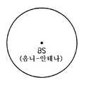
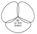
옴니-기지국은 옴니-안테나를 사용하도록 구성되는 기지국이고 섹터 기지국은 복수의(2개 이상의) 섹터 안테나들을 사용하도록 구성된다. 도 1A는 옴니-안테나를 갖는 기지국(BS)에 대한 단일 셀 영역을 보여준다. 옴니-안테나는 셀 영역 전체에 걸쳐 커버리지(coverage)를 제공하도록 360도를 방사한다. 도 1B는 3개의 섹터 안타나를 갖는 기지국(BS)에 대한 단일 셀 영역을 보여준다. 3 섹터 기지국이 통상의 섹터 구성이지만, 더 많은 또는 더 적은 섹터들이 이용될 수 있다. 이 경우, 셀 영역은 3분의 1(third)들로 분할되고, 각 섹터 안테나는 대략 120도의 그의 섹터 영역에 걸쳐 커버리지를 제공하도록 방사하는 (옴니-안테나와 비교하여) 보다 좁은 빔(narrower beam)을 갖는다.The omni-base station is a base station that is configured to use an omni-antenna and the sector base station is configured to use a plurality of (two or more) sector antennas. Figure 1A shows a single cell region for a base station (BS) with an omni-antenna. The omni-antenna radiates 360 degrees to provide coverage throughout the cell area. 1B shows a single cell region for a base station (BS) with three sector hits. Although a three-sector base station is a normal sector configuration, more or fewer sectors may be used. In this case, the cell area is divided into thirds, and each sector antenna has a narrower beam (compared to an omni-antenna) that radiates to provide coverage over its sector area of about 120 degrees. ).
기지국 안테나는 커버리지를 강화하고 직접 무선 신호 전파 경로들에 대한 보다 나은 가능성을 제공하기 위해 흔히 탑에, 기둥에, 빌딩의 상부에 또는 측면에 등과 같은, 높은 위치에 설치된다. 도 2A는 탑(12)의 기부(base)에 위치하는 기지국 유닛(14)을 보여준다. 안테나(10)는 탑(12)의 상부에 설치되고, 피더 케이블(feeder cable)(16), 일반적으로 동축 케이블(coaxial cable) 등을 통해, 기지국 송수신기에 접속된다. 수신된 신호는 피더(16)를 가로지르며 신호 손실을 겪으며, 탑(12)이 높을수록, 피더는 더 길어지고, 손실은 더 커진다. 피더에서의 그러한 신호 손실을 상쇄하기 위해, 수신된 신호가 피더를 통하여 기지국 유닛에 보내지기 전에 수신된 신호를 증폭하기 위해 TMA(tower-mounted amplifier)가 이용될 수 있다. 도 2B는 안테나(10)의 근처에 탑(12)의 상부에 설치된 TMA(18)를 보여준다. 타워 마운티드 유닛(tower mounted unit)은 때때로 마스트 헤드 증폭기(mast head amplifier)라고 불린다. 용어 TMA(tower mounted amplifier)는 일반적으로 본 명세서에서 이 피더 전의(pre-feeder) 증폭 기능을 수행하는 임의의 장치를 포함하기 위해 이용된다.Base station antennas are often installed at elevated locations, such as on towers, columns, on top of buildings, or on the sides, etc., to enhance coverage and provide better possibilities for direct radio signal propagation paths. 2A shows a
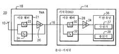
도 3은 옴니-기지국(20)의 단순화된 블록도를 보여준다. 안테나(10)는 수신(Rx) 필터(22) 및 송신(Tx) 필터(24)를 포함하는 TMA(18) 내의 이중 필터(duplex filter)(21)에 접속된다. 이중 필터는 Tx 및 Rx 신호들을 서로 분리함으로써 동일한 안테나에서 송신 및 수신하는 것을 가능하게 한다. 송신 필터(24)는 피더(16)에 직접 접속되고 수신 필터(22)는 LNA(low noise amplifer)(26)를 통해 피더(16)에 접속된다. 피더(16)는 수신 필터(Rx)(30) 및 송신(Tx) 필터(32)를 갖는 이중 필터(28)를 또한 포함하는 기지국(14)에 연결된다. 송신 필터(32)는 수신기(37) 및 송신기(38)를 포함하는 무선 유닛/송수신기(36)에 접속되고, 수신 필터(30)는 LNA(34)를 통해 무선 유닛(36)에 접속된다.3 shows a simplified block diagram of an omni-
송신된 무선 신호들의 수신(또는 송신)을 향상시키기 위해 안테나 다이버시티가 이용될 수 있다. 시간 다이버시티, 공간 다이버시티, 편파(polarization) 다이버시티, 및 그의 조합들과 같은, 많은 종류의 다이버시티가 존재한다. 공간 다이버시티는 수신된 무선 신호들을 페이딩(fading)하는 효과를 감소시킨다. 안테나 다이버시티 시스템은 서로로부터 거리를 두고 배열된 적어도 2개의 안테나를 포함한다. 수신 다이버시티의 경우에는, 수신된 신호가 2개 이상의 안테나에서 수신된다. 다이버시티 안테나들로부터의 수신 Rx 신호들은 강화된 신호를 확득하기 위해 다이버시티 처리를 받는다. 다이버시티 처리는, 예를 들면, 가장 강한 안테나 신호를 선택하는 것, 또는 신호들을 더하고 그 결과의 신호를 더 처리하는 것을 포함할 수 있다. 송신기 다이버시티에서는, 송신 Tx 신호가 송신기에 접속된 2개 이상의 송신 안테나에서 송신된다. 다이버시티 배열의 안테나들은 다이버시티 안테나들이라고 불린다. 다이버시티 배열들에서, 피더 및 그와 관련된 안테나는 다이버시티 브랜치(diversity branch) 또는 단순히 브랜치라고 불릴 수 있다.Antenna diversity may be used to improve reception (or transmission) of the transmitted wireless signals. There are many kinds of diversity, such as time diversity, spatial diversity, polarization diversity, and combinations thereof. Space diversity reduces the effect of fading received radio signals. An antenna diversity system includes at least two antennas arranged at a distance from each other. In the case of receive diversity, the received signal is received at two or more antennas. Received Rx signals from the diversity antennas are subjected to diversity processing to obtain enhanced signals. Diversity processing may include, for example, selecting the strongest antenna signal, or adding signals and further processing the resulting signal. In the transmitter diversity, a transmission Tx signal is transmitted from two or more transmission antennas connected to the transmitter. The antennas of the diversity array are called diversity antennas. In diversity arrangements, the feeder and its associated antenna may be referred to as a diversity branch or simply a branch.
도 4는 다이버시티를 갖는 옴니-기지국(14)의 예를 보여준다. 2개의 다이버시티 안테나들(10a 및 10b)이 대응하는 TMA들(18a 및 18b)에 접속된다. 각 TMA는 대응하는 피더(16a 및 16b)에 의해 기지국(14) 내의 대응하는 이중 필터 및 LNA 유닛(42a 및 42b)에 접속된다. 2개의 이중 필터 및 LNA 유닛들(42a 및 42b)은 단일 무선 유닛(36)에 접속된다.4 shows an example of an omni-
옴니-기지국에서 이용되는 단일 송수신기와 대조적으로, 도 5의 50에 도시된 것과 같은 섹터 기지국은 각 섹터마다 개별 송수신기를 갖는다. 3개의 섹터들이 지원되고 각 섹터는 그 자신의 안테나(101, 102, 및 103)를 갖는다. 안테나들(101, 102, 및 103) 각각은 대응하는 섹터 TMA(181, 182, 및 183)에 접속된다. 3개의 피더들(161, 162, 및 163)이 각각의 TMA(181, 182, 및 183)를 대응하는 기지국 유닛들(141, 142, 및 143)에 연결한다. 기지국들(141, 142, 및 143) 각각은 대응하는 이중 필터 및 LNA 유닛(421, 422, 및 423)을 갖는다. 섹터 기지국은 옴니-기지국보다 더 많은 커버리지를 제공하지만 더 많은 금전 및 전력이 희생된다.In contrast to a single transceiver used in an omni-base station, a sector base station as shown at 50 in FIG. 5 has a separate transceiver for each sector. Three sectors are supported and each sector has its
옴니-기지국들은 섹터 기지국들보다 덜 복잡하고 비용이 덜 들지만, 그것들은 또한 보다 작은 커버리지를 제공하므로, 오퍼레이터는 섹터 기지국들이 설치된 경우보다 특정 지리적 영역을 커버하기 위해 더 많은 옴니-기지국들을 설치해야 한다. 이에 따라, 옴니-기지국이 다중 섹터(multi-sector) 안테나 시스템에 접속되는 다중 섹터 옴니-기지국들이 도입되었다. 사실상, 3 섹터 안테나 시스템이 옴니-기지국과 함께 이용되는 예에서는, 3 섹터 안테나 시스템은 대략 7-8 dB의 신호 이득을 추가한다. 다중 섹터 옴니-기지국의 다른 이점은 섹터 안테나들 중 하나 이상을 "틸트"(tilt), 예를 들면, 다운틸트(downtilt)하는 능력이다. 틸팅은 옴니 안테나들에 대한 옵션은 아니다.Although omni-base stations are less complex and less expensive than sector base stations, they also provide less coverage, so operators must install more omni-base stations to cover a specific geographic area than when sector base stations are installed . Accordingly, multi-sector omni-base stations have been introduced in which an omni-base station is connected to a multi-sector antenna system. In fact, in the example where a three-sector antenna system is used with an omni-base station, the three-sector antenna system adds approximately 7-8 dB of signal gain. Another advantage of multi-sector omni-base stations is the ability to "tilt", eg, downsilt, one or more of the sector antennas. Tilting is not an option for Omni antennas.
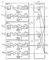
3 섹터 기지국(60)의 예가 도 6A에 도시되어 있다. 3개의 섹터들이 지원되 고 각 섹터는 그 자신의 안테나(101, 102, 및 103)를 갖는다. 안테나들(101, 102, 및 103) 각각은 대응하는 섹터 TMA(181, 182, 및 183)에 접속된다. 3개의 피더들(161, 162, 및 163)이 각각의 TMA들(181, 182, 및 183)을 기지국(14)에 연결한다. 기지국(14)은 3개의 무선 유닛들/송수신기들(36)에 접속된 일반적으로 42로 표시된 3개의 이중 필터 및 LNA 유닛들을 포함한다. 그러나 피더 케이블들, 이중 필터들, 및 송수신기들은 값비싸기 때문에(각 섹터에서 다이버시티가 이용되는 경우에는 더욱 더 값비싸다), 하나의 피더만이 필요하도록 스플리터/컴바이너(splitter/combiner)(44)가 이용된다. 도 6B는 3개의 섹터들(1, 2, 및 3)로부터의 수신된 신호들이 스플리터/컴바이터(44)에서 하나의 피더 케이블(16) 상에 어떻게 함께 결합되는지를 보여준다. 송신 방향으로, 송신 신호는 (보다 낮은 전력의) 3개의 동일한 신호들로 분할되어 각 섹터의 TMA에 제공된다. 만약 캐리어들이 결합 전에 주파수에서 이동되지 않는다면, 수신기는 5 dB 저하(degradation)를 겪는다.An example of a three-
네트워크 오퍼레이터들은 트래픽 볼륨(traffic volume)이 낮은 기간들이 종종 있더라도 피크(peak) 트래픽 볼륨의 시간 기간들 동안의 높은 수요를 만족시키는 충분한 용량을 가져야 한다. 더욱이, 오퍼레이터들은 현저한 시간 지연 및 비용 없이 새로운 용량을 쉽게 추가할 수 있기를 종종 원한다. 더 큰 용량을 제공하기 위해 보다 값비싼 다중 섹터 기지국이 채용될 수 있지만, 그 최대(full) 용량은 통상적으로 피크 기간들 동안에만 필요하다. 오프-피크(off-peak) 시간들 동안에 는, 용량의 일부가 사용되지 않는다. 용량이 사용되지 않을 수 있을지라도, 그것은 미사용 용량이 비용이 없다는 것을 의미하지 않는다. 사실상, 낮은 트래픽 기간들 동안(예를 들면, 밤새도록)의 다중 섹터 기지국의 전력 소비(아이들(idle) 전류)는 에너지 비효율적이다. 그리고 더 많은 용량이 요구되는 경우, 오퍼레이터는 TMA들을 재구성하기 위해 기지국 안테나 탑에 오르는 것과 같은 노동비의 형태의 (장비 비용에 추가되는) 재구성 비용에 직면한다. 요구되는 용량을 제공할 수 있지만 또한 보다 에너지 효율적이고 비용이 덜 드는 다중 섹터 기지국 배열을 제공하는 것이 바람직할 것이다.Network operators should have sufficient capacity to satisfy high demand during the time periods of peak traffic volume, even in periods of low traffic volume. Moreover, operators often want to be able to easily add new capacity without significant time delay and cost. Although a more expensive multi-sector base station may be employed to provide a larger capacity, its full capacity is typically only needed during peak periods. During off-peak times, some of the capacity is not used. Although capacity may not be used, it does not mean that unused capacity is costly. In fact, the power consumption (idle current) of a multi-sector base station during low traffic periods (e.g., overnight) is energy inefficient. And, if more capacity is required, the operator is faced with a reconfiguration cost (in addition to the equipment cost) in the form of labor costs, such as climbing the base station antenna tower to reconstruct the TMAs. It would be desirable to provide a multi-sector base station arrangement that can provide the required capacity but is also more energy efficient and less costly.
다이버시티 수신을 채용하는 다중 섹터 기지국들에서의 다른 문제점은 다이버시티 안테나 출력들이 모두 동일한 TMA에서 처리된다는 것이다. 그 배열은 TMA 유닛들 중 하나가 결함이 생기거나 불능 상태가 되지 않는다면 좋다. 그러한 경우에는, 그 섹터 내의 통신은 완전히 상실된다. 중복된(redundant) 백업 시스템을 추가할 필요 없이 안테나 다이버시티를 채용하는 다중 섹터 기지국들에서의 통신의 신뢰도를 향상시키는 것이 바람직할 것이다.Another problem in multi-sector base stations employing diversity reception is that the diversity antenna outputs are all processed in the same TMA. The arrangement is fine as long as one of the TMA units does not become defective or disabled. In such a case, the communication in the sector is completely lost. It would be desirable to improve the reliability of communication in multi-sector base stations employing antenna diversity without the need to add redundant backup systems.
[개요][summary]
무선 기지국 사이트는 복수의 섹터 안테나 유닛들을 포함한다. 각 섹터 안테나 유닛은 이용 가능한 주파수 대역 내의 안테나 주파수와 관련된 캐리어 신호를 수신하기 위한 안테나를 갖는다. (용어 "주파수 대역"은 주파수들의 범위뿐만 아니라 단일 주파수를 포함한다.) 컨트롤러는, 각 섹터 안테나 유닛이 관련된 필터링 유닛 및 관련된 무선 유닛을 갖는, 다중 섹터 기지국 구성과, 섹터 안테나 유닛 들 중 적어도 2개가 기지국에서 공통의 필터링 유닛 및 공통의 무선 유닛을 공유하는, 다중 섹터 옴니-기지국 구성 사이에 무선 기지국을 자동으로 변환하도록 구성된다. 어느 한쪽 방향으로의 변환은 오퍼레이트 입력, 하루 중의 시간, 검출된 부하 조건, 예측되는 용량 수요 등에 의해 트리거될 수 있다.The wireless base station site includes a plurality of sector antenna units. Each sector antenna unit has an antenna for receiving a carrier signal associated with an antenna frequency in an available frequency band. (The term "frequency band" includes a single frequency as well as a range of frequencies.) The controller includes a multi-sector base station configuration in which each sector antenna unit has an associated filtering unit and associated radio unit, Sector omni-base station configuration in which the base station shares a common filtering unit and a common radio unit at the base station. The conversion in either direction may be triggered by an operator input, a time of day, a detected load condition, a predicted capacity demand, and the like.
다중 섹터 옴니-기지국 구성에 대하여, 안테나 유닛 내의 주파수 변환기는 다중 안테나 유닛들 중 하나에 의해 수신된 캐리어 신호를 안테나 주파수로부터 상이한 각각의 주파수로 변환한다. 협대역 필터는 흥미 있는 이용 가능한 주파수 대역의 일부를 필터링하여 제거한다. 2개 이상의 주파수 변환기가 채용될 수 있다. 컴바이너는 복수의 안테나 유닛들과 관련된 캐리어 신호들을 결합하여 기지국 유닛에 통신하기 위한 합성 신호를 생성한다. 복수의 안테나 유닛들과 관련되고 컴바이너에서 결합된 캐리어 신호들 중 적어도 2개가 피더 상에서 제공되고 상이한 주파수에서 기지국 유닛 내의 수신 회로에 의해 수신된다. 공통의 무선 유닛은 섹터 다이버시티 신호들의 개개의 것들을 추출하기 위한 주파수 변환 회로를 포함한다. 복수의 섹터 신호들이 피더를 통해 기지국에 접속되도록 섹터 신호들 중 하나 이상을 피더에 접속하고 피더 신호를 무선 유닛들에 접속하기 위해 스위칭 회로가 이용될 수 있다. 바람직하게는, 에너지를 절약하기 위해 이 구성에서 관련된 필터링 유닛들 및/또는 무선 유닛들 중 하나 이상이 파워-다운된다(powered-down). 다중 섹터 옴니-기지국 구성에 대한 구현에 따라서는, 대응하는 주파수 변환기를 갖는 복수의 섹터 안테나 유닛들의 수가 복수의 섹터 안테나 유닛들의 수보다 적거나 동일할 수 있다. 컴바이너는 복수의 안테나 유닛들 각각과 관련된 캐리어 신호들을 결합하여, 결합된 캐리어 신호들 모두가 상이한 주파수 대역과 관련되거나 또는 결합될 캐리어 신호들 중 일부만이 상이한 주파수에 있는 합성 신호를 생성할 수 있다.For a multi-sector omni-base station configuration, a frequency converter in the antenna unit converts the carrier signal received by one of the multiple antenna units from an antenna frequency to a respective different frequency. A narrowband filter filters and removes a portion of an interesting available frequency band. More than two frequency converters may be employed. The combiner combines the carrier signals associated with the plurality of antenna units to produce a composite signal for communicating to the base station unit. At least two of the carrier signals associated with the plurality of antenna units and combined at the combiner are provided on the feeder and are received by the receiving circuitry in the base station unit at different frequencies. The common radio unit includes a frequency conversion circuit for extracting individual ones of the sector diversity signals. A switching circuit may be used to connect one or more of the sector signals to the feeder and connect the feeder signal to the wireless units such that the plurality of sector signals are connected to the base station via the feeder. Preferably, one or more of the associated filtering units and / or radio units is powered down in this configuration to conserve energy. Depending on the implementation of the multi-sector omni-base station configuration, the number of the plurality of sector antenna units having the corresponding frequency converters may be less than or equal to the number of the plurality of sector antenna units. The combiner may combine the carrier signals associated with each of the plurality of antenna units such that all of the combined carrier signals are associated with different frequency bands or only a portion of the carrier signals to be combined are at a different frequency .
보다 큰 용량을 얻기 위하여, 다중 섹터 기지국 구성이 이용될 수 있다. 그 구성에서는, 복수의 유닛들 각각과 관련된 신호가 주 기지국 유닛에 접속된 복수의 피더들 중 각각의 것을 통해 제공된다(예를 들면, 스위칭 가능하게). 복수의 섹터 안테나 유닛들 각각으로부터 복수의 피더들 중 각각의 것을 통해 라우팅된 신호는 주 기지국 유닛 내의 복수의 무선 유닛들 중 각각의 것에서 처리하기 위해 제공된다(예를 들면, 스위칭 가능하게).To achieve greater capacity, a multi-sector base station configuration may be used. In that configuration, a signal associated with each of the plurality of units is provided (e.g., switchable) through each of a plurality of feeders connected to the main base station unit. A signal routed through each of the plurality of feeders from each of the plurality of sector antenna units is provided (e.g., switchable) for processing in each of the plurality of radio units in the main base station unit.
다른 유리한 양태는 2개 이상의 섹터를 갖는 기지국들에서의 다이버시티 구현들에 관한 것이다. 각 섹터 안테나 유닛은 제1 다이버시티 안테나 및 제2 다이버시티 안테나에 접속될 수 있고, 다중 섹터 옴니-기지국 구성에 대하여, 각 섹터의 제1 다이버시티 안테나와 관련된 신호들은 결합되어 제1 합성 신호를 생성하고 제1 합성 신호를 기지국 유닛에 접속된 제1 피더 상에 제공할 수 있다. 각 섹터의 제2 다이버시티 안테나들과 관련된 신호들은 결합되어 제2 합성 신호를 생성하고 제2 합성 신호를 기지국 유닛에 접속된 제2 피더 상에 제공할 수 있다. 강화된 기지국 신뢰도를 달성하기 위해, 각 섹터 안테나 유닛은 하나의 섹터로부터의 제1 다이버시티 안테나 신호에 및 상이한 섹터로부터의 제2 다이버시티 안테나 신호에 접속될 수 있다. 기지국 유닛은 각 섹터와 관련된 로컬 발진기를 포함하고, 한편 다중 섹터 옴니-기지국 구성에서는, 합성 신호로부터 동일한 섹터로부터의 다이버시 티 신호들을 추출하기 위해 바람직하게는 로컬 발진기들 중 동일한 것이 이용된다.Another advantageous aspect relates to diversity implementations in base stations having two or more sectors. Each sector antenna unit may be connected to a first diversity antenna and a second diversity antenna, and for a multi-sector omni-base station configuration, the signals associated with the first diversity antenna of each sector are combined to form a first composite signal And provide a first composite signal on a first feeder connected to the base station unit. The signals associated with the second diversity antennas of each sector may be combined to produce a second composite signal and provide a second composite signal on a second feeder connected to the base station unit. To achieve enhanced base station reliability, each sector antenna unit may be connected to a first diversity antenna signal from one sector and to a second diversity antenna signal from a different sector. The base station unit comprises a local oscillator associated with each sector, while in a multi-sector omni-base station configuration, the same of the local oscillators is preferably used to extract the diversity signals from the same sector from the synthesized signal.
또 다른 유리한 양태는 송신기 회로의 선택적인 파워-다운을 허용하는 재구성 가능한 다중 섹터 기지국에 관한 것이다. 기지국은 복수의 섹터 안테나 유닛들 ― 복수의 섹터 안테나 유닛들 각각은 이용 가능한 주파수 대역 내의 안테나 주파수와 관련된 캐리어 신호를 수신하기 위한 안테나를 가짐 ―, 및 복수의 기지국 송수신기들 ― 각 송수신기는 송신 회로 및 수신 회로를 갖고, 각 섹터 안테나 유닛은 복수의 기지국 송수신기들 중 하나에 접속 가능함 ― 을 포함한다. 가장 많은 전력을 소비하는 회로는 기지국의 송신기 측에 있기 때문에, 본 발명자들은 수신기 측을 파워 다운할 필요 없이 소망의 시간 간격 동안 송신기 측을 선택적으로 파워 다운하는 스킴(scheme)을 고안하였다. 그런 식으로 신호들이 여전히 수신될 수 있지만, 상당한 전력이 절약될 수 있다. 따라서, 컨트롤러는 수신 회로를 파워 다운할 필요 없이 전력을 보존하기 위해 소망의 시간 간격 동안 송신 회로를 선택적으로 파워 다운한다. 송신 스플리터를 이용하여, 컨트롤러는, 송신 스플리터가 활성화되어 송신 신호를 2개 이상의 섹터들 각각의 송신 필터에 라우팅하는, 제1 절전 모드(power saving mode)와, 송신 스플리터가 비활성화되어 송신 신호가 그 각각의 기지국 송신기로부터 각 섹터 송신 필터에 연결되는, 제2 보다 고전력 모드(higher power mode) 사이에 선택적으로 스위칭할 수 있다.Another advantageous aspect relates to a reconfigurable multi-sector base station that allows selective power down of the transmitter circuit. The base station having a plurality of sector antenna units each having a plurality of sector antenna units each having an antenna for receiving a carrier signal associated with an antenna frequency in an available frequency band, and a plurality of base station transceivers, And each sector antenna unit is connectable to one of a plurality of base station transceivers. Because the most power consuming circuit is at the transmitter side of the base station, we have devised a scheme for selectively powering down the transmitter side for a desired time interval without having to power down the receiver side. That way signals can still be received, but significant power can be saved. Thus, the controller selectively powers down the transmit circuit for a desired time interval to conserve power without having to power down the receive circuit. Using a transmit splitter, the controller includes a first power saving mode in which the transmit splitter is activated and routes the transmit signal to a transmit filter of each of the two or more sectors, a power saving mode in which the transmit splitter is deactivated, And may switch selectively between a second higher power mode, which is connected to each sector transmit filter from each base station transmitter.
도 1A는 옴니-안테나를 갖는 기지국(BS)에 대한 단일 셀 영역을 도시한다.Figure 1A shows a single cell region for a base station (BS) with an omni-antenna.
도 1B는 3개의 섹터 안테나를 갖는 기지국(BS)에 대한 단일 셀 영역을 도시 한다.1B shows a single cell region for a base station (BS) with a three sector antenna.
도 2A는 기지국 탑을 도시한다.2A shows a base station tower.
도 2B는 TMA(tower-mounted amplifier) 및 스위치/컴바이너 유닛을 갖는 기지국 탑을 도시한다.Figure 2B shows a base station tower with a tower-mounted amplifier (TMA) and a switch / combiner unit.
도 3은 옴니-기지국의 단순화된 블록도를 도시한다.Figure 3 shows a simplified block diagram of an omni-base station.
도 4는 다이버시티를 갖는 옴니-기지국의 예를 도시한다.Fig. 4 shows an example of an omni-base station with diversity.
도 5는 섹터 기지국의 예를 도시한다.5 shows an example of a sector base station.
도 6A는 3 섹터 기지국의 예를 도시한다.6A shows an example of a three sector base station.
도 6B는 스플리터/컴바이너 및 하나의 피더 케이블을 이용하는 3 섹터 옴니-기지국의 예를 도시한다.6B shows an example of a 3-sector omni-base station using a splitter / combiner and one feeder cable.
도 7은 감소된 컴바이너 손실을 갖는 다중 섹터 옴니-기지국의 예의 기능 블록도이다.7 is a functional block diagram of an example of a multi-sector omni-base station with reduced combiner loss.
도 8A는 예를 들면 850 MHz 대역에 대하여 안테나들에서 부대역(subband)들로 분할된 이용 가능한 주파수 대역의 다이어그램이다.8A is a diagram of the available frequency bands, for example, divided into subbands at the antennas for the 850 MHz band.
도 8B는 상이한 섹터 신호들이 피더 상의 이용 가능한 주파수 대역 내의 대응하는 부대역으로 주파수 변환(frequency-translate)되는 예를 도시하는 다이어그램이다.8B is a diagram illustrating an example in which different sector signals are frequency-translated into the corresponding subband in the available frequency band on the feeder.
도 9A는 5 MHz 부대역들로 분할된 PCS 주파수 대역의 다이어그램이다.9A is a diagram of a PCS frequency band divided into 5 MHz subbands.
도 9B는 3개의 상이한 섹터 신호들이 피더 상의 PCS 주파수 대역 내의 대응하는 부대역으로 주파수 변환되는 예를 도시하는 다이어그램이다.9B is a diagram illustrating an example where three different sector signals are frequency converted to the corresponding subband in the PCS frequency band on the feeder.
도 10은 다중 섹터, 옴니-기지국 구성과 다중 섹터 기지국 구성 사이에 기지국을 변환하기 위한 비제한적인 예시 절차들을 개설(outline)하는 순서도이다.10 is a flowchart outlining non-limiting example procedures for transforming a base station between multiple sector, omni- base station configurations and multiple sector base station configurations.
도 11A 및 11B는 다중 섹터, 옴니-기지국 구성과 다중 섹터 기지국 구성 사이에 변환될 수 있는 기지국의 비제한적인 예시 실시예들의 기능 블록도들이다.11A and 11B are functional block diagrams of non-limiting exemplary embodiments of a base station that may be converted between multiple sector, omni-base station and multi-sector base station configurations.
도 12는 다중 섹터, 옴니-기지국 구성과 다중 섹터 기지국 구성 사이에 변환될 수 있는 기지국의 다른 비제한적인 예시 실시예들의 기능 블록도이다.12 is a functional block diagram of other non-limiting exemplary embodiments of base stations that may be converted between multiple sector, omni-base station configurations and multiple sector base station configurations.
도 13A 및 13B는 다중 섹터, 옴니-기지국 구성과 다중 섹터 기지국 구성 사이에 변환될 수 있는 다이버시티 수신을 갖는 기지국의 다른 비제한적인 예시 실시예의 기능 블록도이다.13A and 13B are functional block diagrams of another non-limiting example embodiment of a base station with diversity reception that can be converted between multiple sector, omni-base station and multi-sector base station configurations.
도 14는 다중 섹터, 옴니-기지국 구성과 다중 섹터 기지국 구성 사이에 변환될 수 있는 기지국의 또 다른 비제한적인 예시 실시예의 기능 블록도이다.14 is a functional block diagram of yet another non-limiting exemplary embodiment of a base station that can be converted between multiple sector, omni-base station and multi-sector base station configurations.
도 15는 다중 섹터, 옴니-기지국 구성과 다중 섹터 기지국 구성 사이에 변환될 수 있는 다이버시티 수신을 갖는 기지국의 또 다른 비제한적인 예시 실시예의 기능 블록도이다.15 is a functional block diagram of yet another non-limiting exemplary embodiment of a base station with diversity reception that can be converted between multiple sector, omni-base station and multi-sector base station configurations.
도 16은 송신기 회로의 선택적인 파워-다운을 허용하는 재구성 가능한 다중 섹터 기지국의 비제한적인 예시 실시예의 기능 블록도이다.16 is a functional block diagram of a non-limiting exemplary embodiment of a reconfigurable multi-sector base station that allows selective power down of the transmitter circuitry.
이하의 설명에서는, 설명과 비제한을 위해, 설명된 기술의 이해를 제공하기 위하여, 특정 노드들, 기능 엔티티들, 기법들, 프로토콜들, 표준들 등과 같은, 특정 상세들이 제시된다. 이 기술 분야의 숙련자에게는, 아래 개시되는 특정 상세들은 별문제로 하고 다른 실시예들이 실시될 수 있다는 것이 명백할 것이다. 예를 들면, 다중 섹터 옴니-무선 기지국들 및 다중 섹터 기지국들에 관련해서 예시 실시예들이 설명되지만, 개시된 기술은 또한 다른 유형의 다중 안테나 장치들에 및 실내 및 실외 응용들에 적용될 수 있다. 다른 경우에, 불필요한 상세로 설명을 불명료하게 하지 않기 위해 주지의 방법들, 장치들, 기법들 등의 상세한 설명은 생략된다. 개개의 기능 블록들이 도면들에 도시되어 있다. 이 기술 분야의 숙련자들은 그 블록들의 기능들은 개개의 하드웨어 회로들을 이용하여, 적절하게 프로그램된 마이크로프로세서 또는 범용 프로세서와 함께 소프트웨어 프로그램들 및 데이터를 이용하여, ASIC(application specific integrated circuitry)을 이용하여, 및/또는 하나 이상의 DSP(digital signal processor)를 이용하여 구현될 수 있다는 것을 알 것이다.In the following description, for purposes of explanation and not limitation, specific details are set forth, such as particular nodes, functional entities, techniques, protocols, standards, etc., in order to provide an understanding of the techniques described. It will be apparent to those skilled in the art that the specific details disclosed below are merely illustrative, and that other embodiments may be practiced. For example, although illustrative embodiments have been described with respect to multi-sector omni-wireless base stations and multi-sector base stations, the disclosed techniques may also be applied to other types of multi-antenna devices and to indoor and outdoor applications. In other instances, detailed descriptions of known methods, devices, techniques, and so forth are omitted so as not to obscure the description with unnecessary detail. The individual functional blocks are shown in the figures. Those skilled in the art will appreciate that the functions of the blocks may be accomplished using application specific integrated circuitry (ASIC), using software programs and data, with appropriately programmed microprocessors or general purpose processors, using individual hardware circuits, And / or using one or more digital signal processors (DSPs).
다중 섹터, 옴니-기지국 구성과 다중 섹터 기지국 구성 사이의 변환을 설명하기 전에, 이제 도 7과 관련하여 감소된 컴바이너 손실을 갖는 다중 섹터, 옴니-기지국(70)의 바람직하지만 예시의 실시예를 설명한다. 용어 "다중"(multiple)은 2개 이상을 의미하는 것으로 이해되지만, 이 비제한적인 예시에서는, 3개의 섹터들(S1, S2, 및 S3)이 지원되고, 각 섹터는 그 자신의 안테나(101, 102, 및 103)를 갖는다. 예를 들면, 6개 섹터 등의 다른 다중 섹터 구현들이 이용될 수 있다. 안테나들(101, 102, 및 103) 각각은 비제한적인 방식으로 TMA(tower mounted amplifier)(181, 182, 및 183)라고 불리는 대응하는 섹터 안테나 유닛에 접속된다. 3개의 TMA들(181, 182, 및 183)은, TMA 수신된 신호들을 수신 필터(30) 및 LNA(low noise amplifier)(34)를 포함하는 단일 이중 필터 및 LAN 유닛(42)을 포함하는 옴니-기지국(14)에 연결하기 위해 하나의 피더(16)만이 요구되도록, 스플리터/컴바이너(62)에 접속된다. 단순화를 위하여, 송신 경로는 생략되었다. 각 TMA는 그 각각의 안테나(101, 102, 및 103)에 접속된 수신(Rx) 필터(721, 722, 및 723)를 포함한다.Before describing the conversion between multiple sector, omni-base station and multi-sector base station configurations, a preferred embodiment of a multi-sector, omni-
각 수신 필터(721, 722, 및 723)는 각각의 증폭기(741, 742, 및 743)에 접속되고, 증폭된 출력은 대응하는 믹서(mixer)(761, 762, 및 763)에 접속되고 그 대응하는 믹서에서 그것은 예를 들면 로컬 발진기(781, 782, 및 783)에 의해 생성된 주파수 변환 신호(frequency translating signal)와 혼합된다. 하나의 비제한적인 예시에서, 주파수 변환 신호는, 각 섹터 신호가 상이한 주파수로 변환되도록, 각 섹터마다 상이하다. 각 믹서의 출력은 다른 믹서 산물(mixer products)뿐만 아니라 이용 가능한 대역의 다른 부분들로부터의 잡음 및 간섭을 제거하기 위해 각각의 주파수를 중심으로 한 각각의 협대역(NB) 또는 대역통과 필터(801, 802, 및 803)를 이용하여 필터링된다.Each receive
단지 설명을 위하여 각 섹터 신호가 주파수 변환되는 것으로 도시되어 있지만, 섹터 신호들 중 하나 이상이 주파수 변환되지 않을 수 있다. 바람직하게는, 각 섹터 신호는 결합되어 옴니-무선 기지국 송수신기 유닛에 전송되기 전에 상이한 주파수에 있다. 이 3 섹터 예시에서, 섹터 신호들 중 2개는 상이한 주파수들로 주파수 변환될 수 있는 반면 제3 섹터 신호는 주파수 변환되지 않는다. 그러한 경우에는, 3개의 섹터 신호들은 여전히 상이한 주파수들에 있다. 상이한 주파수들은 f1, f2, 및 f3로서 식별된다. 덜 최적의 예시 구현에서, 섹터 신호들 중 일부는 상이한 주파수들에 있지만 2개 이상의 섹터 신호들은 동일한 주파수에 남아 있다. 이 구현이 덜 최적인 것은, 동일한 주파수의 신호들이 간섭하고 신호 대 잡음비가 컴바이너에서 감소되기 때문이다.Although each sector signal is shown as being frequency converted for illustration only, one or more of the sector signals may not be frequency transformed. Preferably, each sector signal is at a different frequency before being combined and transmitted to the omni- wireless base station transceiver unit. In this three-sector example, two of the sector signals may be frequency converted to different frequencies, while the third sector signal is not frequency transformed. In such a case, the three sector signals are still at different frequencies. The different frequencies are identified as f1 , f2 , and f3 . In a less optimal exemplary implementation, some of the sector signals are at different frequencies, but two or more sector signals remain at the same frequency. This implementation is less optimal because the signals of the same frequency interfere and the signal-to-noise ratio is reduced at the combiner.
비록 필요하지는 않지만, 결합된 신호를 피더(16)를 통하여 송신하기 전에, 그 결합된 신호를 상이한 주파수, 예를 들면, 보다 낮은 주파수로 주파수 변환하는 것이 바람직할 수 있다. 예를 들면, 결합된 신호를 훨씬 더 낮은 주파수로 변환하는 것은 피더(16)에서의 손실을 최소화할 수 있고 따라서 잡음을 더욱 감소시킬 수 있다.Although not required, it may be desirable to frequency translate the combined signal to a different frequency, e.g., a lower frequency, before transmitting the combined signal via the
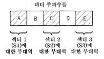
기지국 유닛(14)에서, 피더(16)는 이중 필터 유닛(FU)(42)에 접속하고, 이중 필터 유닛(42)의 수신 필터(30) 및 LNA(34)만이 도시되어 있다. 이중 필터 유닛(42)은 옴니-기지국 무선 유닛(43)에 접속되고, 옴니-기지국 무선 유닛(43)의 일부만이 도시되어 있고 믹서들(821, 822, 및 823)을 포함한다. 통상적으로, 다중 섹터, 옴니-기지국 수신기는 이 스테이지에서 하나의 믹서를 사용할 것이고 그 후 협대역 필터에 의해 수신된 무선 신호를 하향 변환(downconvert)한다. 그러나 이 예시의 섹터 수신 신호들 각각은 상이한 주파수에 있기 때문에, 3개의 상이한 로컬 발진기 신호들(LO1, LO2, 및 LO3)을 포함하는 3개의 무선 유닛들(RU들)(43)이 컴바이너(62)로부터의 합성 신호와 혼합된다. 로컬 발진기들(841, 842, 및 843)은 그 3개의 상이한 로컬 발진기 신호들(LO1, LO2, 및 LO3)을 제공한다. 다른 무선 수신 회로에 더하여, 각 무선 유닛은 또한 전력 증폭기를 포함하는 무선 송신 회로를 포함한다. 도면들을 단순화하기 위해 추가의 무선 유닛 회로는 도시되어 있지 않다. 각 출력은 그 후 그의 각각의 RU(43) 내의 협대역 중간 주파수(IF) 필터(861, 862, 및 863)에서 필터링되어 대응하는 섹터 수신 신호들(Rx1, Rx2, 및 Rx3)을 생성한다. 이들 섹터 수신 신호들(Rx1, Rx2, 및 Rx3)은 추가의 처리를 위해 준비되어 있다.In the
주파수 변환의 설명을 돕기 위해, 이제 도 8A 및 8B와 관련하여 예를 설명한다. 도 8A는 부대역들 A-E로 분할된 이용 가능한 안테나 주파수 대역의 다이어그램이다. 그러나, 부대역 B는 옴니-무선 기지국에 의해 사용되는 주파수 대역이다. 도 8B는 사용되는 부대역 B에서 모두 수신된 3개의 상이한 섹터 신호들이 피더에 대한 이용 가능한 주파수 대역 내의 대응하는 부대역으로 주파수 변환되는 예를 보여주는 다이어그램이다: 부대역들 A, C, 및 E가 이용된다. 섹터 신호들 중 하나는 주파수 변환될 필요가 없고 사용되는 부대역 B에 남아 있을 수 있지만, 이 경우, 보호 대역(guard band)이 없을 것이기 때문에 그것은 바람직하지 않다. 보호 대역을 갖는 것은 섹터 캐리어 신호들 사이의 간섭의 가능성을 감소시킨다.To help explain the frequency conversion, an example is now described with respect to Figures 8A and 8B. 8A is a diagram of the available antenna frequency bands divided into subbands A-E. However, subband B is the frequency band used by the omni- wireless base station. 8B is a diagram showing an example where three different sector signals, all received in sub-band B being used, are frequency transformed to the corresponding sub-band in the available frequency band for the feeder: sub-bands A, C, and E . One of the sector signals need not be frequency transformed and may remain in the used subband B, but in this case it is not desirable because there will be no guard band. Having a guard band reduces the likelihood of interference between sector carrier signals.
이제 도 9A 및 9B와 관련하여 PCS(Personal Communication Service) 대역에서의 실세계 예를 설명한다. 도 9A는 12개의 5 MHz 부대역들 A1, A2, A3, D, B1, B2, B3, E, F, C1, C2, 및 C3로 분할된 1850-1910 MHz로부터의 PCS 주파수 대역에 대한 안테나 주파수들의 다이어그램이다. 무선 기지국에 의한 사용되는 부대역은 1865-1870 MHz로부터의 5 MHz D 대역이다. 이 3 섹터 예시에 대하여, 사용되는 부대역 D에서 모두 수신되는 3개의 상이한 섹터 신호들은 이용 가능한 주파수 대역 내의 대응하는 피더 부대역 주파수로 주파수 변환되고, 그 대응하는 피더 부대역 주파수는 이 예시에서는 도 9B에 도시된 바와 같이 A1, B3, 및 C3이다. 그러나, 섹터 신호들 중 하나는 주파수 변환될 필요가 없고 사용되는 부대역(D)에 남아 있을 수 있고 여전히 3개의 섹터 신호들을 분리하는 보호 대역이 있을 것이다.Now, a real-world example in the PCS (Personal Communication Service) band will be described with reference to FIGS. 9A and 9B. 9A is the 12 5 MHz sub-bandA 1, A 2, A 3 , D,
이 비제한적인 예시에서, 3개의 필터들(721, 722, 및 723)은 각각 1850-1910 MHz로부터의 이용 가능한 60 MHz 주파수 대역을 통과시킨다. 그러나 기지국은 1865-1870 MHz로부터의 5 MHz "D" 부대역만을 사용하고 있다. 제1 섹터 수신 신호는 A1 부대역으로 주파수 편이(frequency shift)되고, NB 필터1은 1850-1865 MHz 사이의 주파수들을 통과시킨다. 제2 섹터 수신 신호는 B3 부대역으로 주파수 편이되고, NB 필터2는 1870-1885 MHz 사이의 주파수들을 통과시킨다. 제3 섹터 수신 신호는 C3 부대역으로 주파수 편이되고, NB 필터3는 1895-1910 MHz 사이의 주파수들을 통과시킨다.In this non-limiting example, the three
피더(16)를 통하여 3개의 상이한 주파수 대역들 A1(1850-1855), B3(1880-1885), C3(1905-1910)에서 3개의 섹터 캐리어들을 운반하는 주파수 다중화된 신호는 옴니-기지국 수신 회로에 의해 처리된다. 수신된 신호는 1850-1910 MHz로부터의 60 MHz 폭 PCS 대역을 통과시키는 수신 필터(30)를 이용하여 필터링된다. 필터링된 신호를 LNA(34)에서 증폭한 후에, 증폭된 수신 신호는 이 예시에서 각 섹터에 대하여 하나씩인, 3개의 믹서들(821, 822, 및 823)에 보내지고, 거기서는 섹터 신호를 피더(16)를 통하여 송신하기 전에 섹터 신호가 주파수 변환되었다. 도시된 수신 회로의 목적은 각 섹터 신호를 동일한 중간 주파수(IF) 신호로 변환하는 것이다. IF 하향 변환은 필터링을 단순화하고 차후의 베이스밴드 처리를 용이하게 한다. 200 MHz의 IF로의 변환을 달성하기 위해, LO1은 1652.5 MHz로 설정되고; LO2는 1682.5 MHz로 설정되고; LO3는 1707.5 MHz로 설정된다. 이 비제한적인 예시에서, 믹서(821)로부터의 200 MHz 출력은 그 후 (200 MHz IF를 중심으로 한) 197.5-202.5 MHz로부터의 주파수들을 통과시키는 3개의 5 MHz NB 필터(861, 862, 및 863) 각각에 의해 필터링된다.A frequency multiplexed signal carrying three sector carriers in three different frequency bands A1 (1850-1855), B3 (1880-1885), and C3 (1905-1910) through the
옴니-무선 기지국과 함께 사용되는 적어도 하나 이상의 섹터 안테나 유닛들에서 수신된 신호들을 주파수 변환하는 것은 섹터 신호들이 주파수 변환 없이 결합될 대 통상적으로 부닥치는 컴바이너 손실을 허용한다. 만약 결합된 3 섹터 옴니-무선 기지국에서의 모든 신호들이 상이한 주파수들에 있다면, 컴바이너에서 대략 5 dB 전력 손실이 회피된다. 그런 식으로 컴바이너에서 실질적인 손실을 초래함이 없이 보다 적은 수의 피더 케이블들이 이용될 수 있다. 실제로, 다이버시티 구현들에서뿐만 아니라 비다이버시티(non-diversity) 구현들에서는 단 하나의 피더 케이블만이 사용될 필요가 있다. 보다 효율적인 다중 섹터 옴니-기지국들은, 옴니-기지국들에 대한 커버리지 및/또는 용량이 섹터 안테나들을 이용하여 증가될 수 있기 때문에, 상업적으로 매력적이다. 실제로, 현존하는 옴니-기지국들은 결합하여 피더 케이블을 통하여 기지국 송수신기에 송신하기 전에 섹터 수신 안테나들 및 주파수 변환을 이용하여 풀 커버리지 기지국들(full coverage base stations)로 쉽게 업그레이드될 수 있다. 다른 이점은 보다 적은 하드웨어가 사용되기 때문에 전력 소비가 더 낮다는 것이다. 예를 들면, 특히 다른 무선 컴포넌트들보다 더 많은 전력을 소비하는 전력 증폭기들의 수가 더 적다.Frequency conversion of received signals in at least one or more sector antenna units used with an omni- wireless base station allows com- biner losses typically encountered when sector signals are combined without frequency conversion. If all of the signals in the combined three-sector omni-radio base station are at different frequencies, approximately 5 dB power loss in the combiner is avoided. In this way, fewer feeder cables can be used without causing substantial losses in the combiner. Indeed, not only in diversity implementations but also in non-diversity implementations, only one feeder cable needs to be used. More efficient multi-sector omni-base stations are commercially attractive because the coverage and / or capacity for omni-base stations can be increased using sector antennas. In practice, existing omni- base stations can be easily upgraded to full coverage base stations using sector receive antennas and frequency translation before combining and transmitting over the feeder cable to the base station transceiver. Another benefit is that the power consumption is lower because less hardware is used. For example, there are fewer power amplifiers that consume more power than other wireless components in particular.
배경기술에서 설명한 바와 같이, 네트워크 오퍼레이터들은 트래픽 볼륨이 낮은 기간들이 종종 있더라도 피크 트래픽 볼륨의 시간 기간들 동안의 높은 수요를 만족시키는 충분한 용량을 가져야 한다. 다중 섹터 옴니-기지국은 그 피크 기간들 동안에 충분한 용량을 제공하지 않을 수 있다. 오퍼레이터들은 또한 현저한 시간 지연 및 비용 없이 새로운 용량을 쉽게 추가할 수 있기를 종종 원한다. 더 큰 용량을 제공하기 위해 보다 값비싼 다중 섹터 기지국이 채용될 수 있지만, 그 최대 용량은 통상적으로 피크 기간들 동안에만 필요하다. 오프-피크 시간들 동안에는, 용량의 일부가 사용되지 않는다. 낮은 트래픽 기간들 동안(예를 들면, 밤새도록)의 다중 섹터 기지국의 전력 소비(예를 들면, 아이들 상태의(idling) 전력 증폭기들에 의해 소비되는 전류)는 에너지 비효율적이다. 그리고 더 많은 용량이 요구되는 경우, 오퍼레이터는 TMA들을 재구성하기 위해 기지국 안테나 탑에 오르는 것과 같은 노동비의 형태의 (장비 비용에 추가되는) 재구성 비용에 직면한다. 이들 문제에 대한 해법은 다중 섹터, 옴니-기지국 구성으로부터 다중 섹터 기지국 구성으로 그리고 그 반대로 자동으로 스위칭될 수 있는 재구성 가능한 기지국이다.As described in the background, network operators must have sufficient capacity to satisfy high demand during the time periods of the peak traffic volume, even in periods of low traffic volume. A multi-sector omni-base station may not provide sufficient capacity during its peak periods. Operators also often want to be able to easily add new capacity without significant time delay and cost. A more expensive multi-sector base station may be employed to provide a larger capacity, but its maximum capacity is typically only needed during peak periods. During off-peak times, some of the capacity is not used. The power consumption of the multi-sector base station during low traffic periods (e.g., overnight) (e.g., current consumed by idling power amplifiers) is energy inefficient. And, if more capacity is required, the operator is faced with a reconfiguration cost (in addition to the equipment cost) in the form of labor costs, such as climbing the base station antenna tower to reconstruct the TMAs. The solution to these problems is a reconfigurable base station that can be switched automatically from multiple sectors, from an omni-base station configuration to a multi-sector base station configuration, and vice versa.
도 10은 복수의 안테나 섹터들을 갖는 재구성 가능한 기지국을 다중 섹터, 옴니-기지국 구성과 다중 섹터 기지국 구성 사이에 자동으로 스위칭하기 위한 비제한적인 예시 절차들을 개설하는 순서도이다. 단계 S1에서는, 복수의 섹터 안테나 유닛들 각각이 이용 가능한 주파수 대역 내의 안테나 주파수와 관련된 캐리어 신호를 수신한다. 복수의 안테나 유닛들 중 하나에 의해 수신된 캐리어 신호는 안테나 주파수로부터 안테나 주파수 대역과는 다른 각각의 주파수로 주파수 변환되고 협대역 필터링이 행해진다(단계 S2). 다중 섹터 옴니-기지국(BS) 구성이 소망되는지에 대한 판정이 행해진다(단계 S3). 어느 한쪽 방향으로의 변환은 오퍼레이트 입력, 하루 중의 시간, 검출된 부하 조건, 예측되는 용량 수요 등에 의해 트리거되고, 전자 컨트롤러에 의해 조정(orchestrate)될 수 있다. 만약 다중 섹터 옴니-기지국(BS) 구성이 선택되지 않고, 예를 들면, 피크 시간 기간을 수용하도록 보다 높은 용량이 요구된다면, 다중 섹터 구성이 소망되고, 각 안테나 유닛 캐리어 신호는 그 자신의 피더를 통하여 기지국 무선 유닛에 라우팅된다(단계 S4). 각 캐리어 신호는 그 자신의 무선 유닛에서 처리되고 추가의 처리를 위해 중간 주파수(IF)로 변환된다.10 is a flowchart outlining non-limiting exemplary procedures for automatically switching a reconfigurable base station having a plurality of antenna sectors between a multi-sector, omni-base station configuration and a multi-sector base station configuration. In step S1, each of the plurality of sector antenna units receives a carrier signal associated with an antenna frequency in an available frequency band. The carrier signal received by one of the plurality of antenna units is frequency-converted from the antenna frequency to each frequency different from the antenna frequency band, and narrowband filtering is performed (step S2). A determination is made whether a multi-sector omni-base station (BS) configuration is desired (step S3). The conversion in either direction may be triggered by an operator input, a time of day, a detected load condition, a predicted capacity demand, etc., and may be orchestrated by an electronic controller. If a multi-sector omni-base station (BS) configuration is not selected and a higher capacity is required to accommodate, for example, a peak time period, then a multiple sector configuration is desired, and each antenna unit carrier signal has its own feeder To the base station radio unit (step S4). Each carrier signal is processed at its own radio unit and converted to an intermediate frequency (IF) for further processing.
그러나 만약 예를 들면 보다 적은 용량이 요구되는 오프-피크 시간 동안이면, 보다 효율적인 다중 섹터, 옴니-기지국 구성이 설정될 수 있다. 비록 이 경우에 다양한 다중 섹터 옴니-기지국 구성들이 도시되어 있지만, 다른 다중 섹터 옴니-기지국 구성들이 이용될 수도 있다. 이 구성에서는 필터 유닛들 및/또는 무선 유닛들 중 하나 이상이 사용될 필요가 없기 때문에, 원한다면 전력을 절약하기 위해 그것들은 비활성화(파워-다운)될 수 있다(단계 S6). 송신기 전력 증폭기를 포함하는 무선 유닛을 비활성화하는 것은 상당한 전력을 절약한다. 복수의 안테나 유닛들(42)과 관련되고 합성 신호를 형성하기 위해 컴바이너에서 결합된 캐리어 신호들 중 적어도 2개는 상이한 주파수에 있다(단계 S7). 합성 신호는 피더를 통하여 기지국 유닛에 전송된다(단계 S8). 상이한 주파수와 관련된 적어도 하나의 캐리어 신호를 추가의 처리를 위해 중간 주파수로 주파수 변환하는 것을 포함하여 합성 신호로부터 각 캐리어 신호가 추출된다(단계 S9).However, if for example during off-peak times where less capacity is required, a more efficient multi-sector, omni-base station configuration can be established. Although various multi-sector omni-base station configurations are shown in this case, other multi-sector omni-base station configurations may be used. In this configuration, since one or more of the filter units and / or the wireless units need not be used, they can be de-energized (power-down) if desired to save power (step S6). Deactivating a radio unit comprising a transmitter power amplifier saves considerable power. At least two of the carrier signals associated with the plurality of
도 11A는 복수의 섹터들을 갖는 재구성 가능한 기지국(90)의 다른 비제한적인 예시 실시예의 기능 블록도이다. 이 예시는 어떤 점에서 도 7에 도시된 기지국과 유사하지만, 여기서는 다중 섹터, 옴니-기지국 구성에 대한 주파수 변환이 안테나 유닛들(18)에서 대신에 스위치/컴바이너(63)에서 수행된다. 3개의 안테나들은, 3개의 수신 필터들, 3개의 LNA들, 3개의 주파수 변환기들, 3개의 협대역 필터들, 및 하나의 피더에 접속된 하나의 스위치/컴바이너를 포함하는 하나의 TMA 유닛에 접속될 수 있다.11A is a functional block diagram of another non-limiting exemplary embodiment of a
또한 도 11A에는 2개의 스위치들(81)이 포함되어 있는데, 그 중 하나는 NB 필터(801)의 출력에 접속되고 그 중 다른 하나는 NB 필터(803)의 출력에 접속된다. 이 스위치들(81)은 컨트롤러(90)로부터의 스위치 제어 신호들(C.S.)에 의해 제어되고, 컨트롤러(90)는 이 예에서는 기지국 유닛(14)에 위치하지만, 또한 스위치들을 동작시키기 위해 그로부터 제어 신호들이 생성되어 통신될 수 있는 임의의 적합한 위치에 위치할 수 있다. 기지국 유닛은 또한 컨트롤러(90)에 의해 제어되는 스위치들(83A 및 83B)의 다른 세트를 포함한다. 스위치들(83A 및 83B)은 필터 신호(들)가 하나의 또는 모든 3개의 무선 유닛들(43) 내의 적절한 믹서(82)에 제공되는 것을 보증한다. 다중 섹터 옴니-기지국 구성에 대응하는 제1 스위치 위치에서, 스위치들(81)은 3개의 NB 필터(80) 출력들을 단일 피더(16)에 연결한다. 그 피더 상의 합성 신호는 중간 필터 유닛(42)에 제공된다. 이 구성에서는, 전력을 절약하기 위해 상부 및 하부 무선 유닛들이 파워-다운될 수 있다. 그 필터 유닛의 출력이 도 7과 관련하여 설명한 바와 같이 필터링된 합성 신호에 작용하는 3개의 무선 유닛들(RU들)(43)에 제공되도록, 스위치들(83A)은 열리고, 스위치들(83B)은 닫힌다. 컨트롤러(90)가 스위치들(81)을 보다 고용량의 다중 섹터 기지국 구성에 대응하는 제2 스위치 위치로 설정할 경우, 스위치들(81)은 필터 출력들을 그들 자신의 각각의 피더(16)에 연결하여 (하나보다는) 3개의 피더들이 사용된다. 각 피더 상의 신호는 그 자신의 필터 유닛(42)에 제공된다. 컨트롤러(90)는 각 필터 유닛의 출력이 그의 각각의 무선 수신 유닛(RU)(43)에서 처리되도록 스위치들(83A)을 닫고 스위치들(83B)을 연다.11A also includes two
상기 예시에서, 섹터 신호들은 기지국 구성에 관계없이 스위치/컴바이너(63)에서 주파수 편이된다. 도 11B는 각 TMA(18)에 추가의 스위치들(85)이 제공되고, 컨트롤러(90)가 이 스위치들(85)을 다중 섹터 기지국 구성에 대응하는 스위치 위치에 설정할 때, TMA에서의 주파수 변환 동작들이 바이패스(bypass)되도록 한 다른 예시 실시예를 보여준다. 이 주파수 변환 동작들은 이 구성에서 불필요하고 원한다면 회피될 수 있다. 원한다면, 다중 섹터 기지국 구성으로 스위칭될 때의 임의의 기지국 구성 변환 구현에서 유사한 바이패스 스위칭이 채용될 수 있다. 그러나 이하의 도면들을 단순화하기 위해, 섹터 안테나 유닛들에서의 바이패스 스위칭 옵션은 생략된다.In this example, the sector signals are frequency shifted in the switch /
도 12는 복수의 섹터들을 갖는 재구성 가능한 기지국(92)의 다른 비제한적인 예시 실시예의 기능 블록도이다. 어떤 점에서 도 11A에서 도시된 재구성 가능한 기지국과 유사하지만, 주파수 변환은 중간 주파수(IF) 변환을 포함한다. 결합 전에 주파수에서 섹터 신호들을 분리하기 위한 주파수 변환을 수행하기 전에 IF 변환이 채용될 수 있는 몇 가지 이유는 다음을 포함한다: (a) IF-필터들은 RF-필터들보다 더 효과적이고, (b) IF 하향 변환(down-conversion) 및 상향 변환(up-conversion)은 RF-RF 변환들보다 더 잘 알려진 기법들이고, (c) 피더 주파수들은 이용 가능한 주파수 대역에서 원하는 곳에 위치할 수 있다. 기지국 내의 믹서들 및 로컬 발진기들은 상이한 주파수들을 추가의 처리를 위해 IF로 하향 변환한다.12 is a functional block diagram of another non-limiting exemplary embodiment of a
도 13A 및 13B는 함께 복수의 섹터들을 갖고 각 섹터는 다이버시티 수신을 포함하는 재구성 가능한 기지국(92)의 다른 비제한적인 예시 실시예의 기능 블록도이다. 각 섹터 TMA(181, 182, 및 183)는 2개의 다이버시티 수신 브랜치들 A 및 B를 갖지만, 원한다면 3개 이상의 다이버시티 브랜치들이 이용될 수 있다. 각 TMA(181, 182, 및 183)는 각각의 제1 안테나(101A, 102A, 및 103A)에 접속된 수신(Rx) 필터(721A, 722A, 및 723A)뿐만 아니라 각각의 제2 안테나(101B, 102B, 및 103B)에 접속된 수신(Rx) 필터(721B, 722B, 및 723B)를 포함한다.13A and 13B are functional block diagrams of another non-limiting example embodiment of a
제1 다이버시티 브랜치 내의 각 수신 필터는 각각의 증폭기(741A, 742A, 및 743A)에 접속되고, 제2 다이버시티 브랜치 내의 각 수신 필터는 각각의 증폭기(741B, 742B, 및 743B)에 접속된다. 제1 브랜치들 각각에 대한 증폭된 출력은 대응하는 제1 믹서(761A, 762A, 및 763A)에 접속되고, 거기서 그것은 예를 들면 각각의 섹터 로컬 발진기(781, 782, 및 783)에 의해 생성된 주파수 변환 신호와 혼합된다. 제2 브랜치들 각각에 대한 증폭된 출력은 대응하는 제2 믹서(761B, 762B, 및 763B)에 접속되고, 거기서 그것은 예를 들면 동일한 각각의 섹터 로컬 발진기(781, 782, 및 783)에 의해 생성된 주파수 변환 신호와 혼합된다. 이 비제한적인 예시에서 주파수 변환 신호는 각 섹터마다 상이하여 각 섹터에 대한 2개의 다이버시티 신호들은 다른 섹터 신호들과는 다른 주파수로 변환된다. 제1 다이버시티 브랜치에서의 각 믹서의 출력은 다른 믹서 산물(mixer products)뿐만 아니라 이용 가능한 대역 내의 잡음 및 간섭을 제거하기 위해 각각의 주파수를 중심으로 한 각각의 협대역(NB) 또는 대역통과 필터(801A, 802A, 및 803A)를 이용하여 필터링된다. 유사하게, 제2 다이버시티 브랜치에서의 각 믹서의 출력은 다른 믹서 산물을 제거하기 위해 각각의 주파수를 중심으로 한 각각의 협대역(NB) 또는 대역통과 필터(801B, 802B, 및 803B)를 이용하여 필터링된다. 각 섹터에서의 2개의 협대역 필터들은 동일한 각각의 주파수를 중심으로 한다.Each receive filter in the first diversity branch is connected to a
스위치/컴바이너(63)는 각 섹터 안테나 유닛(181, 182, 및 183)으로부터의 다이버시티 출력 신호들을 수신한다. 컨트롤러(90)로부터의 제어 신호는 기지국을 다중 섹터 옴니-기지국으로서 또는 다중 섹터 기지국으로서 구성하기 위해 4개의 스위치들(SW)(81)의 위치를 제어한다. 다중 섹터 옴니-기지국 구성에 대응하는 제1 스위치 위치에서는, 스위치들(81)은 각 섹터로부터의 A 다이버시티 브랜치들의 필터 출력들을 단일 피더(16A)에 연결하여, 그것들이 제1 합성 신호를 형성하도록 결합되게 하고, 각 섹터로부터의 B 다이버시티 브랜치들의 필터 출력들을 단일 피더(16B)에 연결하여, 그것들이 제2 합성 신호를 형성하도록 결합되게 한다. 이런 식으로, 상이한 주파수들(f1A, f2A, 및 f3A)의 제1 다이버시티 브랜치들로부터의 TMA 수신 신호들을 기지국 유닛(14)에 연결하기 위해 하나의 피더(16A)만이 요구되고, 상이한 주파수들(f1B, f2B, 및 f3B)의 제2 다이버시티 브랜치들로부터의 TMA 수신 신호들을 기지국 유닛(14)에 연결하기 위해 하나의 피더(16B)만이 요구된다.The switch /
기지국(14)은 6개의 이중 필터 유닛들(42)을 포함한다. 각 필터 유닛(FU)은 예를 들면 이중 필터 및 LNA(low noise amplifier)를 포함한다. 다중 섹터 옴니-기지국 구성에서는 2개의 필터 유닛들만이 사용되고, 바람직하게는 다른 4개의 필터는 이 구성에서 전력을 절약하기 위해 파워-다운된다. 피더(16A)에 연결된 필터 유닛(42)은 (컨트롤러(90)에 의해 닫힌) 스위치들(83B)을 통해 무선 유닛들(RU들)(43) 각각의 믹서들(821A, 822A, 및 823A)에 접속되고, 피더(16B)에 연결된 필터 유닛(42)은 (컨트롤러(90)에 의해 닫힌) 스위치들(83B)을 통해 무선 유닛들(RU들)(43) 각각의 믹서들(821B, 822B, 및 823B)에 접속된다. (스위치들(83A)은 컨트롤러(90)에 의해 열린다). 단일 로컬 발진기(LO1)(841)로부터의 출력은 믹서들(821A 및 821B)에의 입력들과 혼합되어 그 신호들을 IF 또는 다른 소망의 주파수(예를 들면 호모다인(homodyne)에서와 같이 베이스밴드)로 변환하여 861A 및 861B에서 각각 필터링하여 섹터 1로부터의 다이버시티 수신 신호들(Rx1A 및 Rx1B)을 생성한다. 단일 로컬 발진기(LO2)(842)로부터의 출력은 믹서들(822A 및 822B)에의 입력들과 혼합되어 그 신호들을 IF 또는 다른 소망의 주파수로 변환하여 862A 및 862B에서 각각 필터링하여 섹터 2로부터의 다이버시티 수신 신호들(Rx2A 및 Rx2B)을 생성한다. 단일 로컬 발진기(LO3)(843)로부터의 출력은 믹서들(823A 및 823B)에의 입력들과 혼합되어 그 신호들을 IF 또는 다른 소망의 주파수(예를 들면 호모다인에서와 같이 베이스밴드)로 변환하여 863A 및 863B에서 각각 필터링하여 섹터 3로부터의 다이버시티 수신 신호들(Rx3A 및 Rx3B)을 생성한다.The
컨트롤러(80)가 스위치들(81)을 보다 고용량의 다중 섹터 기지국 구성에 대응하는 제2 스위치 위치로 설정할 경우, 스위치들(81)은 필터 출력들을 6개의 피더들(16) 중 그들 각각의 피더에 출력한다. 각각의 피더 상의 신호는 그 자신의 필터 유닛(42)에 제공되고, (컨트롤러(90)에 의해 스위치들(83A)은 닫히고 스위치들(83B)은 열린 상태로), 그 후 그 각각의 수신 유닛(43)에서 처리되어 각 섹터로부터의 다이버시티 수신 신호들을 생성한다: Rx1A 및 Rx1B, Rx2A 및 Rx2B, Rx3A 및 Rx3B.When the
도 14는 다중 섹터, 옴니-기지국 구성과 다중 섹터 기지국 구성(96) 사이에 변환될 수 있는 수신 다이버시티를 갖는 재구성 가능한 기지국의 또 다른 비제한적인 예시 실시예의 기능 블록도이다. 이 비제한적인 예시에서는, 3개의 섹터들(S1-S3)이 있고, 각 섹터는 2개의 다이버시티 안테나들(10A 및 10B)을 포함한다. 각 다이버시티 안테나는 이 예시에서 상이한 주파수의 출력 신호(f1A-f3B의 각각의 것)를 생성하는 그 자신의 TMA(181A-183B의 각각의 것)를 갖는다. 컨트롤러(90)로부터의 제어 신호는 기지국을 다중 섹터 옴니-기지국 구성으로서 또는 다중 섹터 기지국 구성으로서 구성하기 위해 스위치들(SW)(81, 83A 및 83B)의 위치를 제어한다. 다중 섹터 옴니-기지국 구성에 대응하는 제1 스위치 위치에서는, 스위치들(81)은 6개의 상이한 주파수 캐리어들(f1A-f3B)을 단일 합성 신호로 연결하고 이 단일 합성 신호는 그 후 단일 피더(16)를 통하여 기지국 유닛(14)에 전송된다. 이 비제한적인 예시에서 각 섹터 다이버시티 신호는 상이한 주파수에 있기 때문에, 그것들은 컴바이너(63) 또는 피더(16)에서 직접 간섭하지 않는다. 컨트롤러(90)는 스위치들(83B)을 닫고 스위치들(83A)을 열어, 믹서들(82)이 f2A 피더에 연결된 필터 유닛(42)에 접속되도록 한다.14 is a functional block diagram of yet another non-limiting exemplary embodiment of a reconfigurable base station with receive diversity that can be transformed between multiple sector, omni- base station configurations and multiple sector
도 13A 및 13B의 예시 실시예와 비교하여, 기지국이 다중 섹터, 옴니-기지국으로서 구성되는 경우 하나 더 적은 수의 컴바이너 및 하나 더 적은 수의 피더가 이용되어, 비용이 절약된다. 불리점은, 기지국에 할당되는 이용 가능한 주파수 대역의 크기에 따라서는, 6개의 TMA 신호들(f1A-f3B) 각각의 사이에 보호 대역이 거의 없거나 전혀 없을 수 있다는 것이다. 그 결과, 간섭이 추가될 수 있고, 따라서 신호 대 잡음비가 감소될 수 있다. 또한, 도 13의 예시 실시예에서의 2개와 비교하여, 기지국 유닛(14)에서는 단 하나의 이중 수신 필터(30) 및 LAN(34)가 요구된다. 한편, 각각의 믹서들(821A-823B)에 6개의 상이한 로컬 발진기 신호들(LO1A-LO3B)을 제공하기 위해 6개(3개와 비교됨)의 상이한 로컬 발진기들(841A-843B)이 요구된다.Compared to the exemplary embodiment of Figs. 13A and 13B, when the base station is configured as a multi-sector, omni-base station, one fewer combiners and one fewer feeders are used, saving cost. The disadvantage is that depending on the size of the available frequency band allocated to the base station, there may be little or no guard band between each of the six TMA signals f1A -f3B . As a result, interference can be added, and thus the signal-to-noise ratio can be reduced. Also, as compared to the two in the exemplary embodiment of FIG. 13, the
컨트롤러(90)가 스위치들(81, 83A, 및 83B)을 보다 고용량의 다중 섹터 기지국 구성에 대응하는 제2 스위치 위치로 설정할 경우, 스위치들(81)은 필터 출력들을 6개의 피더들(16) 중 그들 각각의 피더에 출력한다. 각각의 피더 상의 신호는 그 자신의 필터 유닛(42)에 제공되고, 스위치들(83A)은 닫히고 스위치들(83B)은 열린 상태로, 각 피더 신호는 그 후 그 각각의 수신 유닛(43)에서 처리되어 각 섹터로부터의 다이버시티 수신 신호들을 생성한다: Rx1A 및 Rx1B, Rx2A 및 Rx2B, Rx3A 및 Rx3B.When the
배경설명에서 설명한 바와 같이, 다이버시티 수신을 채용하는 다중 섹터 기지국들에서의 문제점은 특정 섹터에 대한 다이버시티 안테나 출력들이 모두 통상적으로 동일한 TMA에서 처리된다는 것이다. 그 배열은 TMA 유닛들 중 하나가 결함이 생기거나 불능 상태가 되지 않는다면 좋다. 그러한 경우에는, 그 섹터 내의 통신은 완전히 상실되거나 또는 심하게 손상될 수 있다. 도 13의 예시에서는, 섹터 1로부터의 2개의 다이버시티 브랜치 신호들 1A 및 1B가 동일한 안테나 유닛(181)에서 처리된다. 만약 그 안테나 유닛이 제대로 작동하지 않는다면, 섹터 전체가 처리되지 않을 수 있다. 본 발명자들은 중복된(redundant) 백업 시스템을 필요로 하지 않는 안테나 다이버시티를 채용하는 다중 섹터 기지국들에서의 통신의 신뢰도를 향상시키는 방법을 발견하였다.As described in the background, a problem with multi-sector base stations employing diversity reception is that all diversity antenna outputs for a particular sector are typically processed in the same TMA. The arrangement is fine as long as one of the TMA units does not become defective or disabled. In such a case, communication within the sector may be completely lost or seriously compromised. In the example of FIG. 13, two
도 15는 다중 섹터, 옴니-기지국 구성과 다중 섹터 기지국 구성 사이에 변환될 수 있고 향상된 신뢰도 및 내고장성(fault tolerance)을 갖는 수신 다이버시티를 갖는 재구성 가능한 기지국의 또 다른 비제한적인 예시 실시예의 기능 블록도이다. 이 예시에서의 기지국은 각 섹터마다 A 다이버시티 브랜치 안테나 및 B 다이버시티 브랜치 안테나를 갖는 3개의 섹터들을 포함한다. 안테나 유닛들(181, 182, 및 183) 각각은 상이한 섹터 안테나들로부터의 다이버시티 브랜치 신호들을 수신한다. 이 예에서, 제1 안테나 유닛(181)은 섹터 1로부터의 다이버시티 신호들 1A 및 1B보다는 섹터 1A(S1A) 및 섹터 3B(S3B)로부터의 다이버시티 신호들을 수신한다. 제2 안테나 유닛(182)은 섹터 2A(S2A) 및 섹터 1B(S1B)로부터의 다이버시티 신호들을 수신한다. 제3 안테나 유닛(183)은 섹터 3A(S3A) 및 섹터 2B(S2B)로부터의 다이버시티 신호들을 수신한다. 이런 식으로 안테나 유닛(181)이 어떻게든 해서 제대로 작동하지 않아 다이버시티 브랜치 신호 S1A가 상실된다 하더라도, 다른 다이버시티 브랜치 S1B도 상실되지는 않는다. 대신에, 다른 다이버시티 브랜치 S1B는 다른 안테나 유닛(182)에서 처리되고, 이는 섹터 1로부터의 신호들이 여전히 수신되지만, 무선 조건에 따라서 어쩌면 다소 감소된 신호 품질로 수신된다는 것을 의미한다.15 illustrates another non-limiting example embodiment of a reconfigurable base station with receive diversity that can be converted between multi-sector, omni-base station and multi-sector base station configurations and has improved reliability and fault tolerance. Block diagram. The base station in this example includes three sectors with an A diversity branch antenna and a B diversity branch antenna for each sector. Each of
도 15의 예시에서, 스위치들(87)이 안테나 유닛들에 포함된다. 대시 기호로 되지 않은 선들(non-dashed lines)은 다중 섹터 옴니-기지국 구성에서의 동작을 위한 신호 경로들을 나타낸다. 그 구성에서는, 스위치들(87)은 각 안테나 유닛(18)에서의 다이버시티 브랜치 신호들을 함께 연결한다. 비결합 모드(uncombined mode)에서는, 예를 들면, 각각의 주파수들 f1A 및 f3B로 편이된 다이버시티 브랜치 신호들 S1A 및 S3B는 개별적으로 컴바이너(63)에 제공된다. 컴바이너(63)는 3개의 상이한 주파수들 f1A-f3A에 대한 브랜치 A 상의 모든 섹터 신호들을 하나의 피더(16) 상에 결합하고 그 합성 신호를 기지국(14) 내의 상부 필터 유닛(42)에 제공한다. 컴바이너(63)는 3개의 상이한 주파수들 f1B, f2B, 및 f3B에 대한 다이버시티 B 브랜치들 상의 모든 섹터 신호들을 하나의 피더 브랜치 B 피더(16) 상에 결합하고 그 합성 신호를 기지국(14) 내의 중간 필터 유닛(42)에 제공한다. 그 필터 유닛(42)은 필터링된 합성 신호를 주파수 하향 변환하여 원래의 섹터 신호들을 복구하기 위해 상부 수신 유닛(43)에 제공한다. 3개의 로컬 발진기들(841, 842, 및 843)이 수신 유닛(43)에 포함된다. 합성 신호는 동일한 섹터로부터의 모든 다이버시티 브랜치 신호들을 추출하기 위해 동일한 로컬 발진기가 이용될 수 있도록 RU(43)에서 분할되어 제공된다. 제1 로컬 발진기(841)는 믹서들(821A 및 821B)과 함께 합성 신호로부터 제1 섹터에 대한 A 및 B 다이버시티 브랜치 신호들을 추출하기 위해 이용되고, 합성 신호의 분할된 부분은 믹서들 모두에 제공된다. 제2 로컬 발진기(842)는 믹서들(822A 및 822B)과 함께 제2 섹터에 대한 A 및 B 다이버시티 브랜치 신호들을 추출하기 위해 이용된다. 제3 로컬 발진기(843)는 믹서들(823A 및 823B)과 함께 제3 섹터에 대한 A 및 B 다이버시티 브랜치 신호들을 추출하기 위해 이용된다.In the example of Fig. 15, switches 87 are included in the antenna units. Non-dashed lines represent signal paths for operation in a multi-sector omni-base station configuration. In that configuration, the
이 다중 섹터 옴니-기지국 구성에서, 제3 필터 및 (송신기 전력 증폭기들을 포함하는) 제2 및 제3 무선 유닛들은 전력을 절약하기 위해 비활성화된다. 스위치들이 컨트롤러(90)로부터의 제어 신호들에 의해 다중 섹터 기지국 구성으로 설정되는 경우, 상부 2개의 피더들(16)이 이용된다. 섹터 신호들 S1A, S2A, 및 S3A는 상부 피더 상에 결합되고, 섹터 신호들 S1B, S2B, 및 S3B는 중간 피더 상에 결합된다. 신호가 각 무선 유닛(43)에서 분할되기 때문에 스위치들(83A 및 83B)은 이용되지 않는다. 컴바이너(63) 내의 스위치들(81)이 (스플리터/컴바이너(63)에서 대시 기호로 된 선들로 표시된) 다중 섹터 기지국 구성에 대하여 설정되는 경우, 3개의 피더들(16)이 이용되고 제1 피더(16)는 주파수들 f1A 및 f3B를 운반하고, 제2 피더(16)는 주파수들 f2A 및 f1B를 운반하고, 제3 피더(16)는 주파수들 f3A 및 f2B를 운반한다.In this multi-sector omni-base station configuration, the third filter and the second and third radio units (including the transmitter power amplifiers) are deactivated to conserve power. When the switches are set to the multi-sector base station configuration by control signals from the
이 구성의 중요한 이점은 TMA 유닛들(18) 중 하나가 결함이 생기거나 불능 상태가 되는 경우에, 그 섹터에서의 통신이 상실되거나 또는 반드시 손상되지도 않는다는 것이다. 도 15의 예시에서는, 섹터 1로부터의 2개의 다이버시티 브랜치 신호들 1A 및 1B가 상이한 안테나 유닛들(181 및 182)에서 처리된다. 어느 한쪽의 안테나 유닛이 제대로 작동하지 않는다 하더라도, 다른 안테나는 섹터 1에 대한 다이버시티 브랜치 신호들 중 하나의 처리를 허용한다. 이러한 향상된 신뢰도는 중복된 백업 시스템의 비용 및 복잡성을 요구하지 않고 달성된다. 다른 이점은 하나의 로컬 발진기(84)가 2개의 브랜치들을 만족시킬 수 있다는 것인데, 그 이유는 브랜치들의 신호들이 상이한 피더들 상에 배치되어, 그 2개의 브랜치들에 대하여 피더 상에서 동일한 주파수를 이용하는 것이 가능하기 때문이다.An important advantage of this configuration is that in the event that one of the
도 16은 기지국 내의 송신기 회로의 선택적인 파워-다운을 허용하는 재구성 가능한 다중 섹터 기지국의 또 다른 비제한적인 예시 실시예의 기능 블록도이다. 가장 많은 전력을 소비하는 회로는 기지국의 송신기 측에 있기 때문에, 본 발명자들은 수신기 측을 파워 다운할 필요 없이 소망의 시간 간격 동안 송신기 측을 선택적으로 파워 다운하는 스킴(scheme)을 고안하였다. 그런 식으로 신호들이 여전히 수신될 수 있지만, 상당한 전력이 절약될 수 있다. 컨트롤러(90)의 제어 하에 몇 개의 스위치들(94)이 제공될 수 있다. 그 스위치들은 송신기 필터(TX)(24)가 수신기 필터(RX)(22)로부터 분리되어 있는 임의의 적당한 위치에 배치될 수 있고, 이 예시에서, 그것들은 각 TMA(18) 내에 위치한다.16 is a functional block diagram of another non-limiting exemplary embodiment of a reconfigurable multi-sector base station that allows selective power-down of transmitter circuitry within a base station. Because the most power consuming circuit is at the transmitter side of the base station, we have devised a scheme for selectively powering down the transmitter side for a desired time interval without having to power down the receiver side. That way signals can still be received, but significant power can be saved.
절전 모드에서는 다중 섹터 송신이 여전히 달성될 수 있도록 하나의(여기서는 상부) 피더로부터 각 TMA에 송신 신호를 제공하기 위해 송신(TX) 스플리터(92)가 이용될 수 있다. 만약 각 TMA 내의 각각의 스위치(94)가 점선으로 도시된 제1 위치로 설정된다면, TX 스플리터(92)로부터의 송신 신호는 3개의 섹터 각각에서의 송신을 위해 TX 이중 필터(24)에 접속된다. 이 구성에서는, 전력을 절약하기 위해 하나의(또는 어쩌면 2개의) 송신기(38)만이 파워-업되지만(powered-up), 송신은 여전히 모든 3개의 섹터에서 수행된다. 송신기들(38) 중 2개(또는 그 이상)는 전력을 절약하기 위해 파워-다운된다. 만약 스위치(94)가 각 TMA 내의 다른 수직 위치로 설정된다면, TX 스플리터(92)는 오프되고, 각 기지국 송신기(38)로부터의 각 송신 신호는 그의 각각의 피더(16)를 통해 송신된다. 이 다른 수직 스위치 위치에서는, 기지국은 모든 3개의 송신기들(38)을 이용하는 보다 고전력 모드에서 동작하도록 구성된다. 즉, 모든 3개의 전력 증폭기들이 활성이다. 비록 도 16은 도 15에서 도시된 것과 유사한 양방향 다이버시티 배열로서 도시되어 있지만, 다른 다이버시티 배열들이 이용될 수 있고, 또는 다이버시티가 이용될 필요가 없을 수 있다.In the power save mode, a transmit (TX)
위에 설명한 예시들과 같은(그러나 그에 제한되지 않는) 재구성 가능한 기지국은 네트워크 오퍼레이터들이 피크 트래픽 볼륨의 시간 기간들 동안의 높은 수요를 만족시키는 충분한 용량을 제공하면서도 그와 동시에 트래픽 볼륨이 낮을 경우 용량 및 불필요한 조작성의 비용을 감소시키는 것을 가능하게 한다. 그 재구성 가능한 용량은 지연 또는 비용 없이 추가 또는 제거될 수 있다. TMA들을 재구성하기 위해 기지국 안테나 탑에 오르는 것과 같은 기지국 재구성 노동비가 회피된다. 요구되는 용량은 빠르고 자동화된 기지국 재구성을 융통성 있게 허용하는 값싸고, 에너지 효율적인 방법으로 제공될 수 있다. 또한, 동일한 섹터로부터의 다이버시티 브랜치 신호들을 상이한 안테나 유닛들에서 처리함으로써 중복된 시스템을 추가할 필요 없이 기지국 신뢰도가 향상된다.Reconfigurable basestations such as (but not limited to) the examples described above provide network operators with sufficient capacity to meet high demand during peak periods of peak traffic volume, while at the same time providing low capacity and unnecessary Thereby making it possible to reduce the cost of operability. The reconfigurable capacity may be added or removed without delay or cost. A base station reconfiguration labor cost, such as climbing to the base station antenna tower to reconstruct the TMAs, is avoided. The required capacity can be provided in an inexpensive, energy-efficient way to allow for fast and automated base station reconfigurability. In addition, by processing diversity branch signals from the same sector in different antenna units, the reliability of the base station is improved without the need to add redundant systems.
다양한 실시예들이 상세히 도시되고 설명되었지만, 청구항들은 어떤 특정한 실시예 또는 예시에도 제한되지 않는다. 상기 설명의 어느 것도 임의의 특정 요소, 단계, 범위, 또는 기능이 필수적이어서 그것이 청구항 범위에 포함되어야 한다는 것을 의미하는 것으로 해석되지 않아야 한다. 특허받는 내용의 범위는 청구항들에 의해서만 정의된다. 법적 보호의 한도는 허가된 청구항들에 기재된 말들 및 그와 동등한 것들에 의해 정의된다. 단어 "means for"(~를 위한 수단)가 사용되지 않는 한 어떤 청구항도 35 USC §112의 6항(paragraph 6)에 호소하는 것이 의도되지 않는다.While various embodiments have been shown and described in detail, the claims are not limited to any particular embodiment or illustration. Nothing in the above description should be construed as indicating that any particular element, step, range, or function is essential and that it should be included in the claims. The scope of the patented content is defined only by the claims. The limit of legal protection is defined by the words listed in the licensed claims and equivalents thereof. No claim is intended to appeal to 35 USC §112, paragraph 6, unless the word "means for" is used.
Claims (39)
Translated fromKoreanApplications Claiming Priority (3)
| Application Number | Priority Date | Filing Date | Title |
|---|---|---|---|
| US11/798,921US20080287163A1 (en) | 2007-05-17 | 2007-05-17 | Method and apparatus for converting between a multi-sector, omni-base station configuration and a multi-sector base station configuration |
| US11/798,921 | 2007-05-17 | ||
| PCT/SE2007/050518WO2008143567A1 (en) | 2007-05-17 | 2007-07-10 | Method and apparatus for converting between a multi-sector, omni-base station configuration and a multi-sector base station configuration |
Related Child Applications (1)
| Application Number | Title | Priority Date | Filing Date |
|---|---|---|---|
| KR1020147004062ADivisionKR101493660B1 (en) | 2007-05-17 | 2007-07-10 | Method and apparatus for converting between a multi-sector, omni-base station configuration and a multi-sector base station configuration |
Publications (2)
| Publication Number | Publication Date |
|---|---|
| KR20100016591A KR20100016591A (en) | 2010-02-12 |
| KR101493541B1true KR101493541B1 (en) | 2015-02-13 |
Family
ID=40028032
Family Applications (2)
| Application Number | Title | Priority Date | Filing Date |
|---|---|---|---|
| KR1020097023879AExpired - Fee RelatedKR101493541B1 (en) | 2007-05-17 | 2007-07-10 | Method and apparatus for converting between a multi-sector, omni-base station configuration and a multi-sector base station configuration |
| KR1020147004062AExpired - Fee RelatedKR101493660B1 (en) | 2007-05-17 | 2007-07-10 | Method and apparatus for converting between a multi-sector, omni-base station configuration and a multi-sector base station configuration |
Family Applications After (1)
| Application Number | Title | Priority Date | Filing Date |
|---|---|---|---|
| KR1020147004062AExpired - Fee RelatedKR101493660B1 (en) | 2007-05-17 | 2007-07-10 | Method and apparatus for converting between a multi-sector, omni-base station configuration and a multi-sector base station configuration |
Country Status (6)
| Country | Link |
|---|---|
| US (2) | US20080287163A1 (en) |
| EP (1) | EP2151016A4 (en) |
| KR (2) | KR101493541B1 (en) |
| CN (1) | CN101836496B (en) |
| AU (1) | AU2007353897B2 (en) |
| WO (1) | WO2008143567A1 (en) |
Families Citing this family (53)
| Publication number | Priority date | Publication date | Assignee | Title |
|---|---|---|---|---|
| WO2005088764A1 (en)* | 2004-03-11 | 2005-09-22 | Telefonaktiebolaget Lm Ericsson (Publ) | Method, device, base station and site for reducing the number of feeders in an antenna diversity diversity system. |
| DE602004012331T2 (en) | 2004-06-15 | 2009-03-19 | Telefonaktiebolaget Lm Ericsson (Publ) | ANTENNA DIVERSITY ARRANGEMENT AND PROCEDURE |
| US8706165B2 (en)* | 2006-01-25 | 2014-04-22 | Telefonaktiebolaget Lm Ericsson (Publ) | Method and apparatus for reducing combiner loss in a multi-sector, omni-base station |
| GB0616449D0 (en)* | 2006-08-18 | 2006-09-27 | Quintel Technology Ltd | Diversity antenna system with electrical tilt |
| US8032100B2 (en)* | 2007-06-29 | 2011-10-04 | Delphi Technologies, Inc. | System and method of communicating multiple carrier waves |
| US20090023477A1 (en)* | 2007-07-19 | 2009-01-22 | Telefonaktiebolaget Lm Ericsson (Publ) | Method and apparatus for reconfiguring a multi-sector base station |
| DE102007034977A1 (en)* | 2007-07-26 | 2009-01-29 | Lanxess Deutschland Gmbh | Phthalate-free isocyanurate preparations |
| GB2452029B (en)* | 2007-08-07 | 2011-07-13 | Motorola Inc | Base station arrangement for a cellular communication system |
| US8594733B2 (en)* | 2008-03-08 | 2013-11-26 | Qualcomm Incorporated | Methods and apparatus for using polarized antennas in wireless networks including single sector base stations |
| US8594732B2 (en)* | 2008-03-08 | 2013-11-26 | Qualcomm Incorporated | Methods and apparatus for using polarized antennas in wireless networks including multi-sector base stations |
| US10425284B2 (en) | 2008-05-13 | 2019-09-24 | Apple Inc. | Device, method, and graphical user interface for establishing a relationship and connection between two devices |
| WO2010035922A1 (en)* | 2008-09-26 | 2010-04-01 | Kmw Inc. | Antenna for base station of mobile communication system |
| CN101742621A (en)* | 2008-11-26 | 2010-06-16 | 中国移动通信集团湖南有限公司 | A method, device and system for reducing energy consumption of a base station |
| US8588854B2 (en) | 2008-12-19 | 2013-11-19 | Telefonaktiebolaget L M Ericsson (Publ) | Adaptive transmission selection |
| WO2010117313A1 (en)* | 2009-04-08 | 2010-10-14 | Telefonaktiebolaget Lm Ericsson (Publ) | Data communication scheduling |
| EP2561724A4 (en)* | 2010-04-21 | 2013-10-02 | Ericsson Telefon Ab L M | Method to get a frequency reference to a base station |
| US20110292868A1 (en)* | 2010-05-25 | 2011-12-01 | Sk E Uml A Ee Rby Ulf | Method and Apparatus for Increasing the Capacity and Coverage of a Multi-Sector, Omni Site |
| CN101969686A (en)* | 2010-10-14 | 2011-02-09 | 无锡博欧电子科技有限公司 | Base station radio frequency switching equipment |
| WO2012091639A1 (en)* | 2010-12-27 | 2012-07-05 | Telefonaktiebolaget L M Ericsson (Publ) | Methods and devices for cell re-configuration |
| US9112570B2 (en)* | 2011-02-03 | 2015-08-18 | Rf Micro Devices, Inc. | Femtocell tunable receiver filtering system |
| WO2012177191A1 (en)* | 2011-06-20 | 2012-12-27 | Telefonaktiebolaget L M Ericsson (Publ) | Methods and arrangements to save energy consumption in a network node |
| EP2724591B1 (en) | 2011-06-22 | 2017-03-01 | Telefonaktiebolaget LM Ericsson (publ) | Adaptive filtering architecture |
| CN102882573A (en)* | 2011-07-14 | 2013-01-16 | 中国移动通信集团设计院有限公司 | Multiple-input multiple-output signal transmission realization method, device and system |
| US9408026B2 (en) | 2011-10-04 | 2016-08-02 | Telefonaktiebolaget Lm Ericsson (Publ) | Methods and arrangements for positioning in wireless communications systems |
| EP2842237A4 (en)* | 2012-04-25 | 2015-12-09 | Ericsson Telefon Ab L M | Power saving in a multiple sector radio base station |
| EP2875665A1 (en) | 2012-07-18 | 2015-05-27 | Telefonaktiebolaget LM Ericsson (PUBL) | Performance-based cell aggregation in a mobile network |
| US9240813B2 (en) | 2012-12-05 | 2016-01-19 | Telefonaktiebolaget L M Ericsson (Publ) | Distributed digitally convertible radio (DDCR) |
| WO2014143776A2 (en) | 2013-03-15 | 2014-09-18 | Bodhi Technology Ventures Llc | Providing remote interactions with host device using a wireless device |
| EP2822185B1 (en)* | 2013-07-01 | 2021-06-16 | Nxp B.V. | A distributed radio system |
| WO2015009211A1 (en)* | 2013-07-18 | 2015-01-22 | Telefonaktiebolaget L M Ericsson (Publ) | Methods and devices for cell reconfiguration |
| US9473228B2 (en)* | 2014-01-31 | 2016-10-18 | Qualcomm Incorporated | Variable diversity RX bandwidth for self-organizing networks |
| US9247326B2 (en) | 2014-01-31 | 2016-01-26 | Google Inc. | Systems and methods for increasing bandwidth in a computer network |
| WO2015166305A1 (en) | 2014-04-30 | 2015-11-05 | Telefonaktiebolaget L M Ericsson (Publ) | Multi-sector antenna integrated radio unit |
| US9712226B2 (en) | 2014-05-15 | 2017-07-18 | Qualcomm Incorporated | Multi-way diversity receiver with multiple synthesizers in a carrier aggregation transceiver |
| US10313506B2 (en) | 2014-05-30 | 2019-06-04 | Apple Inc. | Wellness aggregator |
| CN105282831A (en)* | 2014-06-30 | 2016-01-27 | 中兴通讯股份有限公司 | Base station power saving control method and device |
| EP3484134B1 (en) | 2015-02-02 | 2022-03-23 | Apple Inc. | Device, method, and graphical user interface for establishing a relationship and connection between two devices |
| WO2016144385A1 (en) | 2015-03-08 | 2016-09-15 | Apple Inc. | Sharing user-configurable graphical constructs |
| US10275116B2 (en) | 2015-06-07 | 2019-04-30 | Apple Inc. | Browser with docked tabs |
| US11303346B2 (en) | 2015-08-25 | 2022-04-12 | Cellium Technologies, Ltd. | Systems and methods for transporting signals inside vehicles |
| US10027374B1 (en)* | 2015-08-25 | 2018-07-17 | Cellium Technologies, Ltd. | Systems and methods for wireless communication using a wire-based medium |
| AU2017100667A4 (en) | 2016-06-11 | 2017-07-06 | Apple Inc. | Activity and workout updates |
| US10873786B2 (en) | 2016-06-12 | 2020-12-22 | Apple Inc. | Recording and broadcasting application visual output |
| US11816325B2 (en) | 2016-06-12 | 2023-11-14 | Apple Inc. | Application shortcuts for carplay |
| KR102578502B1 (en) | 2016-08-01 | 2023-09-15 | 삼성전자주식회사 | Electronic device comprising antenna |
| US10461828B2 (en)* | 2017-12-27 | 2019-10-29 | Intel IP Corporation | Millimeter wave distributed network antenna sector switch |
| DK180171B1 (en) | 2018-05-07 | 2020-07-14 | Apple Inc | USER INTERFACES FOR SHARING CONTEXTUALLY RELEVANT MEDIA CONTENT |
| CN108988903B (en)* | 2018-07-23 | 2020-09-01 | Oppo广东移动通信有限公司 | RF systems and electronic equipment |
| WO2020020110A1 (en)* | 2018-07-23 | 2020-01-30 | Guangdong Oppo Mobile Telecommunications Corp., Ltd. | Receiving module, transmitting module, and radio frequency system |
| CN109982240B (en)* | 2019-03-11 | 2020-10-27 | 中山大学 | Wireless positioning base station laying method |
| US11863700B2 (en) | 2019-05-06 | 2024-01-02 | Apple Inc. | Providing user interfaces based on use contexts and managing playback of media |
| EP4323992B1 (en) | 2021-05-15 | 2025-05-14 | Apple Inc. | User interfaces for group workouts |
| US12257900B2 (en) | 2022-08-14 | 2025-03-25 | Apple Inc. | Cruise control user interfaces |
Citations (3)
| Publication number | Priority date | Publication date | Assignee | Title |
|---|---|---|---|---|
| WO1999026317A1 (en)* | 1997-11-14 | 1999-05-27 | Radio Design Innovation Tj Ab | An antenna system with a feeder cable |
| US20050215288A1 (en)* | 2004-03-26 | 2005-09-29 | Nortel Networks Limited | Feeder cable reduction |
| US20070142057A1 (en) | 2005-12-15 | 2007-06-21 | Fujitsu Limited | Dynamic cell reconfiguring method and cellular network system to which the method is applied |
Family Cites Families (21)
| Publication number | Priority date | Publication date | Assignee | Title |
|---|---|---|---|---|
| US5021801A (en)* | 1989-09-05 | 1991-06-04 | Motorola, Inc. | Antenna switching system |
| US5627879A (en)* | 1992-09-17 | 1997-05-06 | Adc Telecommunications, Inc. | Cellular communications system with centralized base stations and distributed antenna units |
| JP2576388B2 (en)* | 1993-11-08 | 1997-01-29 | 日本電気株式会社 | Base station transceiver |
| ZA95797B (en)* | 1994-02-14 | 1996-06-20 | Qualcomm Inc | Dynamic sectorization in a spread spectrum communication system |
| US5548813A (en)* | 1994-03-24 | 1996-08-20 | Ericsson Inc. | Phased array cellular base station and associated methods for enhanced power efficiency |
| FI944346L (en)* | 1994-09-19 | 1996-03-20 | Nokia Telecommunications Oy | Base station |
| US5861844A (en)* | 1994-11-29 | 1999-01-19 | Qualcomm Incorporated | Method and apparatus for providing redundant coverage within a cellular communication system |
| JPH1013887A (en)* | 1996-06-27 | 1998-01-16 | Matsushita Electric Ind Co Ltd | Mobile terminal |
| WO1998026614A2 (en)* | 1996-12-09 | 1998-06-18 | Siemens Aktiengesellschaft | Base station for a radio telecommunications system |
| US6118984A (en)* | 1997-04-08 | 2000-09-12 | Acer Peripherals, Inc. | Dual conversion radio frequency transceiver |
| US6411825B1 (en)* | 1997-09-09 | 2002-06-25 | Samsung Electronics, Co., Ltd. | Distributed architecture for a base station transceiver subsystem |
| GB2332822B (en)* | 1997-12-23 | 2002-08-28 | Northern Telecom Ltd | Communication device having a wideband receiver and operating method therefor |
| US6181276B1 (en)* | 1998-10-09 | 2001-01-30 | Metawave Communications Corporation | Sector shaping transition system and method |
| US6519260B1 (en)* | 1999-03-17 | 2003-02-11 | Telefonaktiebolaget Lm Ericsson (Publ) | Reduced delay priority for comfort noise |
| EP1111812A1 (en)* | 1999-12-20 | 2001-06-27 | Nortel Matra Cellular | Omni transmit and sectored receive cellular telecommunications network and method of operating the same |
| DE60323541D1 (en)* | 2002-12-16 | 2008-10-23 | Research In Motion Ltd | METHOD AND DEVICE FOR REDUCING ENERGY CONSUMPTION IN A CDMA COMMUNICATION DEVICE |
| US7340280B2 (en)* | 2004-02-26 | 2008-03-04 | Nokia Corporation | Method of configuring base station, and base station |
| WO2005088764A1 (en)* | 2004-03-11 | 2005-09-22 | Telefonaktiebolaget Lm Ericsson (Publ) | Method, device, base station and site for reducing the number of feeders in an antenna diversity diversity system. |
| GB0426354D0 (en)* | 2004-12-01 | 2005-01-05 | Quintel Technology Ltd | Sectorisation of cellular radio |
| FI117684B (en)* | 2004-12-02 | 2007-01-15 | Filtronic Comtek Oy | Antenna head filter arrangement |
| CN101185200B (en)* | 2005-11-14 | 2011-07-20 | 桥扬科技有限公司 | Multiple Antenna Systems for Cellular Communications and Broadcasting |
- 2007
- 2007-05-17USUS11/798,921patent/US20080287163A1/ennot_activeAbandoned
- 2007-07-10WOPCT/SE2007/050518patent/WO2008143567A1/enactiveApplication Filing
- 2007-07-10KRKR1020097023879Apatent/KR101493541B1/ennot_activeExpired - Fee Related
- 2007-07-10CNCN2007800530006Apatent/CN101836496B/ennot_activeExpired - Fee Related
- 2007-07-10EPEP07769064.2Apatent/EP2151016A4/ennot_activeWithdrawn
- 2007-07-10KRKR1020147004062Apatent/KR101493660B1/ennot_activeExpired - Fee Related
- 2007-07-10AUAU2007353897Apatent/AU2007353897B2/ennot_activeCeased
- 2010
- 2010-02-18USUS12/656,850patent/US20100151908A1/ennot_activeAbandoned
Patent Citations (4)
| Publication number | Priority date | Publication date | Assignee | Title |
|---|---|---|---|---|
| WO1999026317A1 (en)* | 1997-11-14 | 1999-05-27 | Radio Design Innovation Tj Ab | An antenna system with a feeder cable |
| US20050215288A1 (en)* | 2004-03-26 | 2005-09-29 | Nortel Networks Limited | Feeder cable reduction |
| US20070142057A1 (en) | 2005-12-15 | 2007-06-21 | Fujitsu Limited | Dynamic cell reconfiguring method and cellular network system to which the method is applied |
| JP2007166353A (en) | 2005-12-15 | 2007-06-28 | Fujitsu Ltd | Dynamic cell reconfiguration method and cellular network system to which the method is applied |
Also Published As
| Publication number | Publication date |
|---|---|
| WO2008143567A1 (en) | 2008-11-27 |
| CN101836496A (en) | 2010-09-15 |
| AU2007353897A1 (en) | 2008-11-27 |
| US20100151908A1 (en) | 2010-06-17 |
| KR101493660B1 (en) | 2015-02-13 |
| AU2007353897B2 (en) | 2012-08-30 |
| EP2151016A4 (en) | 2014-05-07 |
| CN101836496B (en) | 2013-12-25 |
| KR20100016591A (en) | 2010-02-12 |
| US20080287163A1 (en) | 2008-11-20 |
| EP2151016A1 (en) | 2010-02-10 |
| KR20140031403A (en) | 2014-03-12 |
Similar Documents
| Publication | Publication Date | Title |
|---|---|---|
| KR101493541B1 (en) | Method and apparatus for converting between a multi-sector, omni-base station configuration and a multi-sector base station configuration | |
| KR101336531B1 (en) | Method and apparatus for reducing combiner loss in a multi-sector, omni-base station | |
| KR101442051B1 (en) | Active electrical tilt antenna apparatus with distributed amplifier | |
| US20120098695A1 (en) | Antenna arrangement | |
| RU2342784C2 (en) | Device and expedient of spatial diversity of antennas | |
| EP1726098A1 (en) | Multimode/multiband mobile station and method for operating the same | |
| CA2838740A1 (en) | Distributed antenna system architectures | |
| US20020103001A1 (en) | Dynamic capacity allocation of in-building system | |
| US12278685B2 (en) | Repeater system | |
| CN101321011B (en) | Interconnection method and system for remote radio frequency units | |
| US7162266B2 (en) | Multiple band handset architecture | |
| CN113382484A (en) | Customer premises equipment | |
| US8099133B2 (en) | Apparatus and a method for directing a received signal in an antenna system | |
| CN111130584B (en) | A listening circuit and device applied to an integrated pico base station | |
| EP2101541A1 (en) | Radio head for roads or rurual environments | |
| CN102638299B (en) | Method and system for interconnecting remote radio units | |
| CN120034231A (en) | Electronic devices | |
| KR20250129760A (en) | Multiband radio frequency front-end circuit | |
| KR100299092B1 (en) | Apparatus for processing as to radio frequency of base station | |
| CN118337231A (en) | Radio frequency architecture and electronic equipment | |
| RU2355079C2 (en) | Antenna spacing system | |
| WO2008037160A1 (en) | Radio receiving system, method and duplexer | |
| KR20000062871A (en) | Dual carrier, three-sector configuration for a cdma transmitter/receiver | |
| KR19980039204A (en) | Radio frequency circuit of small base station in mobile communication system by code division multiple access method |
Legal Events
| Date | Code | Title | Description |
|---|---|---|---|
| PA0105 | International application | St.27 status event code:A-0-1-A10-A15-nap-PA0105 | |
| PG1501 | Laying open of application | St.27 status event code:A-1-1-Q10-Q12-nap-PG1501 | |
| A201 | Request for examination | ||
| P11-X000 | Amendment of application requested | St.27 status event code:A-2-2-P10-P11-nap-X000 | |
| P13-X000 | Application amended | St.27 status event code:A-2-2-P10-P13-nap-X000 | |
| PA0201 | Request for examination | St.27 status event code:A-1-2-D10-D11-exm-PA0201 | |
| E902 | Notification of reason for refusal | ||
| PE0902 | Notice of grounds for rejection | St.27 status event code:A-1-2-D10-D21-exm-PE0902 | |
| A107 | Divisional application of patent | ||
| E13-X000 | Pre-grant limitation requested | St.27 status event code:A-2-3-E10-E13-lim-X000 | |
| P11-X000 | Amendment of application requested | St.27 status event code:A-2-2-P10-P11-nap-X000 | |
| P13-X000 | Application amended | St.27 status event code:A-2-2-P10-P13-nap-X000 | |
| PA0104 | Divisional application for international application | St.27 status event code:A-0-1-A10-A18-div-PA0104 St.27 status event code:A-0-1-A10-A16-div-PA0104 | |
| PE0801 | Dismissal of amendment | St.27 status event code:A-2-2-P10-P12-nap-PE0801 | |
| E902 | Notification of reason for refusal | ||
| PE0902 | Notice of grounds for rejection | St.27 status event code:A-1-2-D10-D21-exm-PE0902 | |
| T11-X000 | Administrative time limit extension requested | St.27 status event code:U-3-3-T10-T11-oth-X000 | |
| P11-X000 | Amendment of application requested | St.27 status event code:A-2-2-P10-P11-nap-X000 | |
| P13-X000 | Application amended | St.27 status event code:A-2-2-P10-P13-nap-X000 | |
| E701 | Decision to grant or registration of patent right | ||
| PE0701 | Decision of registration | St.27 status event code:A-1-2-D10-D22-exm-PE0701 | |
| PR0701 | Registration of establishment | St.27 status event code:A-2-4-F10-F11-exm-PR0701 | |
| PR1002 | Payment of registration fee | St.27 status event code:A-2-2-U10-U12-oth-PR1002 Fee payment year number:1 | |
| PG1601 | Publication of registration | St.27 status event code:A-4-4-Q10-Q13-nap-PG1601 | |
| FPAY | Annual fee payment | Payment date:20180129 Year of fee payment:4 | |
| PR1001 | Payment of annual fee | St.27 status event code:A-4-4-U10-U11-oth-PR1001 Fee payment year number:4 | |
| FPAY | Annual fee payment | Payment date:20190125 Year of fee payment:5 | |
| PR1001 | Payment of annual fee | St.27 status event code:A-4-4-U10-U11-oth-PR1001 Fee payment year number:5 | |
| PC1903 | Unpaid annual fee | St.27 status event code:A-4-4-U10-U13-oth-PC1903 Not in force date:20200210 Payment event data comment text:Termination Category : DEFAULT_OF_REGISTRATION_FEE | |
| PC1903 | Unpaid annual fee | St.27 status event code:N-4-6-H10-H13-oth-PC1903 Ip right cessation event data comment text:Termination Category : DEFAULT_OF_REGISTRATION_FEE Not in force date:20200210 |