KR101491704B1 - Apparatus for acquiring image information using implant - Google Patents
Apparatus for acquiring image information using implantDownload PDFInfo
- Publication number
- KR101491704B1 KR101491704B1KR20130049006AKR20130049006AKR101491704B1KR 101491704 B1KR101491704 B1KR 101491704B1KR 20130049006 AKR20130049006 AKR 20130049006AKR 20130049006 AKR20130049006 AKR 20130049006AKR 101491704 B1KR101491704 B1KR 101491704B1
- Authority
- KR
- South Korea
- Prior art keywords
- tray
- image information
- subject
- unit
- acquiring
- Prior art date
- Legal status (The legal status is an assumption and is not a legal conclusion. Google has not performed a legal analysis and makes no representation as to the accuracy of the status listed.)
- Active
Links
Images


Classifications
- A—HUMAN NECESSITIES
- A61—MEDICAL OR VETERINARY SCIENCE; HYGIENE
- A61C—DENTISTRY; APPARATUS OR METHODS FOR ORAL OR DENTAL HYGIENE
- A61C9/00—Impression cups, i.e. impression trays; Impression methods
- A61C9/004—Means or methods for taking digitized impressions
- A61C9/0046—Data acquisition means or methods
- A—HUMAN NECESSITIES
- A61—MEDICAL OR VETERINARY SCIENCE; HYGIENE
- A61C—DENTISTRY; APPARATUS OR METHODS FOR ORAL OR DENTAL HYGIENE
- A61C19/00—Dental auxiliary appliances
- A61C19/04—Measuring instruments specially adapted for dentistry
- A61C19/05—Measuring instruments specially adapted for dentistry for determining occlusion
- A—HUMAN NECESSITIES
- A61—MEDICAL OR VETERINARY SCIENCE; HYGIENE
- A61C—DENTISTRY; APPARATUS OR METHODS FOR ORAL OR DENTAL HYGIENE
- A61C8/00—Means to be fixed to the jaw-bone for consolidating natural teeth or for fixing dental prostheses thereon; Dental implants; Implanting tools
- A61C8/0001—Impression means for implants, e.g. impression coping
- A—HUMAN NECESSITIES
- A61—MEDICAL OR VETERINARY SCIENCE; HYGIENE
- A61C—DENTISTRY; APPARATUS OR METHODS FOR ORAL OR DENTAL HYGIENE
- A61C9/00—Impression cups, i.e. impression trays; Impression methods
- A61C9/0006—Impression trays
- A—HUMAN NECESSITIES
- A61—MEDICAL OR VETERINARY SCIENCE; HYGIENE
- A61C—DENTISTRY; APPARATUS OR METHODS FOR ORAL OR DENTAL HYGIENE
- A61C2201/00—Material properties
- A61C2201/005—Material properties using radio-opaque means
Landscapes
- Health & Medical Sciences (AREA)
- Life Sciences & Earth Sciences (AREA)
- General Health & Medical Sciences (AREA)
- Epidemiology (AREA)
- Dentistry (AREA)
- Animal Behavior & Ethology (AREA)
- Oral & Maxillofacial Surgery (AREA)
- Public Health (AREA)
- Veterinary Medicine (AREA)
- Orthopedic Medicine & Surgery (AREA)
- Engineering & Computer Science (AREA)
- Biomedical Technology (AREA)
- Biophysics (AREA)
- Dental Prosthetics (AREA)
Abstract
Translated fromKoreanDescription
Translated fromKorean본 발명은, 임플란트용 영상정보 획득장치에 관한 것으로서, 보다 상세하게는, 피시술자의 구강구조에 대한 영상정보와 피시술자의 구강 모형에서 얻어진 영상정보를 간편하고 정확하게 매칭(matching)시킬 수 있는 임플란트용 영상정보 획득장치에 관한 것이다.The present invention relates to an image acquisition device for an implant, and more particularly, to an implant image acquisition device capable of easily and accurately matching image information obtained from an oral cavity model of an assistant's mouth structure Information acquiring apparatus.
치과용 임플란트는 원래 인체조직이 상실되었을 때, 회복시켜 주는 대치물을 의미하지만, 치과에서는 인공으로 만든 치아를 이식하는 일련의 시술을 가리킨다.A dental implant is a substitute that restores when the original tissue is lost, but in dentists it refers to a series of procedures for implanting an artificial tooth.
상실된 치근(뿌리)을 대신할 수 있도록 인체에 거부반응이 없는 티타늄(titanium) 등으로 만든 치근인 픽스츄어(fixture)를 치아가 빠져나간 치조골에 심은 뒤, 인공치아를 고정시켜 치아의 기능을 회복하도록 하는 시술이다.In order to replace the missing root (root), a tooth fixture, made of titanium or the like, which has no rejection to the human body, is planted in the alveolar bone that has exited the tooth, and then the artificial tooth is fixed to restore the function of the tooth .
일반 보철물이나 틀니의 경우, 시간이 지나면 주위 치아와 뼈가 상하지만 임플란트는 주변 치아조직을 상하지 않게 하며, 자연치아와 기능이나 모양이 같으면서도 충치가 생기지 않으므로 반영구적으로 사용할 수 있는 장점이 있다.In general prostheses or dentures, the surrounding teeth and bones are damaged over time, but the implants do not injure the surrounding dental tissue, and they have the same function and shape as the natural teeth, but do not have cavities. Therefore, they can be used semi-permanently.
인공치아 시술(임플란트 또는 임플란트 시술이라고도 함)은, 픽스츄어의 종류에 따라 다양하지만 소정의 드릴을 사용하여 식립위치를 천공한 후 픽스츄어를 치조골에 식립하여 뼈에 골융합시킨 다음, 픽스츄어에 지대주(abutment)를 결합시킨 후에, 지대주에 최종 보철물을 씌움으로써 완료되는 것이 일반적이다.The artificial tooth procedure (also referred to as an implant or implant procedure) varies depending on the type of fixture, but after a predetermined drill is used to perforate the fixation position, the fixture is placed on the alveolar bone to perform an artificial fusion to the bone, After the abutments are combined, it is common to finish the abutment with a final prosthesis.
치과용 임플란트는 단일 결손치 수복은 물론이거니와 부분 무치아 및 완전 무치아 환자에게 의치의 기능을 증진시키고, 치아 보철 수복의 심미적인 면을 개선시키며, 나아가 주위의 지지골 조직에 가해지는 과도한 응력을 분산시킴과 아울러 치열의 안정화에 도움을 준다.Dental implants enhance the function of dentures in single-tooth restorations, as well as in partial and total toothless patients, improve the aesthetic aspects of dental prosthesis restoration, and further dissipate excessive stresses on the surrounding supporting bone tissue It helps to stabilize the dentition as well as sikim.
이러한 치과용 임플란트는 일반적으로, 인공 치근으로서 식립되는 픽스츄어(Fixture)와, 픽스츄어 상에 결합되는 지대주(Abutment)와, 지대주를 픽스츄어에 고정하는 지대주 스크류(Abutment Screw)와, 지대주에 결합되는 인공치아를 포함한다. 여기서, 지대주를 픽스츄어에 결합시키기 전에, 즉 치조골에 픽스츄어가 골융합되기까지의 기간 동안에 지대주가 픽스츄어에 결합되어 결합 상태를 유지하기도 한다.Such a dental implant generally includes a fixture to be placed as an artificial root, an abutment to be coupled onto the fixture, an abutment screw to fix the abutment to the fixture, Of the artificial teeth. Here, the abutment is engaged with the fixture before the abutment is coupled to the fixture, that is, during the period until the fixture is fusion-bonded to the alveolar bone, thereby maintaining the engagement state.
치과용 임플란트의 한 구성요소인 픽스츄어는, 임플란트가 시술되는 위치에 드릴 등을 이용하여 치조골에 형성된 드릴 홀에 식립되는 부분으로서 인공 치근의 역할을 담당한다. 따라서 픽스츄어는 치조골에 견고하게 식립되어야 한다.The fixture, which is a component of the dental implant, serves as an artificial root as a part to be placed in a drill hole formed in the alveolar bone using a drill or the like at a position where the implant is performed. Therefore, the fixture should be securely mounted on the alveolar bone.
이에, 픽스츄어의 외면에는 드릴 홀을 형성하는 치조골의 내측벽 부분에 견고히 결합될 수 있도록 나사부(나사산)가 형성된다. 이러한 나사부는 치조골에 인입되어 픽스츄어와 치조골이 견고히 결합될 수 있도록 할 뿐만 아니라 픽스츄어와 치조골의 접촉면적을 증대시킴으로써 치조골에 대한 픽스츄어의 고정력, 특히 초기 고정력(initial stability)을 강화시키는 역할을 한다.Thus, a screw thread is formed on the outer surface of the fixture so as to be firmly engaged with the inner wall portion of the alveolar bone forming the drill hole. Such a screw portion is inserted into the alveolar bone to securely fix the fixture and the alveolar bone, as well as to increase the contact area between the fixture and the alveolar bone, thereby enhancing the fixing force of the fixture to the alveolar bone, particularly the initial stability do.
이처럼 치과용 임플란트 시술은 드릴을 이용하여 치조골에 홀을 천공한 후, 천공된 홀에 픽스츄어를 식립하고, 이어 골융합이 진행되면 픽스츄어에 지대주를 결합시키고 최종적으로 인공 치아(보철물)를 씌우는 단계로 진행된다.In the dental implant procedure, a hole is drilled in the alveolar bone using a drill, a fixture is placed in the drilled hole, and then, when the fusion is completed, the alveolar bone is bonded to the fixture and finally the artificial tooth (prosthesis) Lt; / RTI >
한편 이러한 치과용 임플란트 시술에 있어서, 구강내 치조골에 대한 픽스츄어의 식립 위치, 방향, 깊이를 유도하는 가이드 스텐트를 제작하기 위해서는 환자의 구강내 영상정보인 CT나 MRI와 같이 피술자의 해부학적 정보를 포함하는 영상 데이터가 필수적으로 필요하고, 이와는 별도로 피시술자의 구강내 조직을 본뜬 구강모형의 영상 데이터가 필요한 경우도 많다.In order to manufacture a guide stent for guiding the position, direction and depth of the fixture to the alveolar bone in the dental implant, anatomical information of the subject such as CT or MRI In addition, there are many cases in which image data of an oral cavity model simulating the tissue of the mouth of a patient is required in many cases.
피시술자의 해부학적 정보를 포함하는 영상정보와 피시술자의 구강내 조직을 본뜬 구강모형 3차원스캐닝 하여 얻은 정보는 CAD/CAM 장비에서 가이드 스텐트를 제작하기 위한 정보로 사용된다.The image information including the anatomical information of the physician and the information obtained by 3D scanning of the mouth model simulating the intraoral tissue of the patient are used as information for producing the guide stent in CAD / CAM equipment.
즉 가이드 스텐트는 잇몸, 치아, 뼈에 대응하는 음형을 갖게 제작되어야 하며, 따라서 가이드 스텐트는 CT와 같은 해부학적 정보를 담은 영상을 활용하여 형상을 설계해야만 한다.In other words, the guide stent should be designed to have a shape corresponding to the gums, teeth, and bones. Therefore, the guide stent must be designed using an image containing anatomical information such as CT.
그런데 CT나 MRI 같은 해부학적 정보를 담은 영상은 해상도가 떨어지거나, 치아가 금속으로된 보철물일 경우에 Metal Artifact와 같은 영상불순물 또는 왜곡이 발생될 수 있으며 이를 보완하기 위해 피시술자의 구강내 조직을 본뜬 구강모형을 3차원 스캐닝 하여 얻은 데이터를 활용한다.However, images containing anatomical information such as CT or MRI may show image impurities or distortions such as metal artifacts when the resolution is low or the teeth are made of metal. In order to compensate for this, We use the data obtained by scanning the mouth model three-dimensionally.
이러한 피시술자의 해부학적 정보를 포함하는 영상정보와 피시술자의 구강내 조직을 본뜬 구강모형 3차원 스캐닝 하여 얻은 정보를 CAD/CAM 장비에 사용하기 위해서는 CAD/CAM 장비의 좌표계와 피시술자의 해부학적 정보를 포함하는 영상정보와 피시술자의 구강내 조직을 본뜬 구강모형 3차원 스캐닝 하여 얻은 정보의 좌표를 일치시키는 작업이 반드시 수행되어야 한다.In order to use the information obtained by 3D scanning of the oral cavity model, which is based on the image information including the anatomical information of the subject, and the oral tissue of the subject, the CAD / CAM equipment coordinate system and the anatomical information of the patient are included And the coordinate of the information obtained by 3D scanning of the mouth model simulating the in-vivo tissue of the recipient must be performed.
즉 별개의 좌표를 갖는 피시술자의 해부학적 정보를 포함하는 영상정보와 피시술자의 구강내 조직을 본뜬 구강모형 3차원스캐닝 하여 얻은 정보의 좌표를 일치시키는 매칭(matching)과정이 필수적으로 수행되어야 한다.That is, a matching process that coincides the coordinates of the information obtained by the 3D model scanning of the oral cavity model of the subject with the image information including the anatomical information of the subject who has different coordinates must be performed indispensably.
그런데 종래기술에 있어서 피시술자의 해부학적 정보를 포함하는 영상정보와 피시술자의 구강내 조직을 본뜬 구강모형 3차원스캐닝 하여 얻은 정보를 매칭하는 과정이 복잡하여 많은 시간이 소요되는 문제점이 있다.However, in the related art, there is a problem that the process of matching the image information including the anatomical information of the wearer with the information obtained by the three-dimensional scanning of the mouth model simulating the mouth tissue of the wearer is time consuming.
따라서 피시술자의 해부학적 정보를 포함하는 영상정보와 피시술자의 구강내 조직을 본뜬 구강모형 3차원 스캐닝 하여 얻은 정보를 간편하게 빠르게 매칭시킬 수 있는 임플란트용 영상정보 획득장치의 개발이 필요한 실정이다.Therefore, it is necessary to develop a device for acquiring image information for implants that can quickly and easily match the information obtained by the 3D model scanning of the oral cavity model of the patient with the image information including the anatomical information of the patient.
따라서 본 발명의 해결하고자 하는 과제는, 피시술자의 해부학적 정보를 포함하는 영상정보와 피시술자의 구강내 조직을 본뜬 구강모형 3차원 스캐닝 하여 얻은 정보를 간편하게 빠르게 매칭시킬 수 있는 임플란트용 영상정보 획득장치를 제공하는 것이다.SUMMARY OF THE INVENTION Accordingly, it is an object of the present invention to provide an apparatus and method for acquiring image information for an implant that can easily and quickly match information obtained by three-dimensional scanning of an oral cavity model based on image information including anatomical information of a subject, .
본 발명의 일 측면에 따르면, 피시술자의 구강 내에 삽입되어 상기 피시술자의 구강 형상을 획득하는 인상재가 수용되는 인상용 트레이부; 상기 인상용 트레이부가 상기 피시술자의 구강 내에 삽입된 상태에서 상기 피시술자의 구강구조에 대한 제1 영상정보를 획득하는 제1 영상획득부; 상기 인상재에 의해 획득된 상기 피시술자의 구강 형상으로 제작된 구강 모형에 상기 인상용 트레이부가 삽입된 상태에서 상기 구강 모형에 대한 제2 영상정보를 획득하는 제2 영상획득부; 및 상기 인상용 트레이부에 결합되며, 상기 제1 영상정보와 상기 제2 영상정보의 매칭 기준이 되도록 상기 제1 영상정보와 상기 제2 영상정보에 표시되는 기준부를 포함하는 임플란트용 영상정보 획득장치가 제공될 수 있다.According to an aspect of the present invention, there is provided an image forming apparatus, comprising: a tray portion for receiving an impression material inserted into an oral cavity of a person to be examined and acquiring an oral shape of the subject; A first image acquiring unit acquiring first image information on the oral cavity structure of the subject while the lifting tray is inserted into the mouth of the subject; A second image acquiring unit for acquiring second image information of the oral cavity model in a state where the pull-up tray is inserted into the oral cavity model of the subject who is acquired by the impression material; And a reference part coupled to the pull-up tray part and being displayed on the first image information and the second image information so as to be a reference for matching the first image information and the second image information, May be provided.
상기 기준부는 상기 피시술자의 구강 외부에 배치될 수 있다.The reference portion may be disposed outside the oral cavity of the subject.
상기 기준부는 다면체 형상의 기준 블록을 포함할 수 있다.The reference portion may include a polygonal reference block.
상기 기준 블록은, 제1 모서리; 상기 제1 모서리에 연결되는 제2 모서리; 및 상기 제1 및 제2 모서리에 연결되는 제3 모서리를 포함할 수 있다.The reference block comprising: a first edge; A second edge coupled to the first edge; And a third edge coupled to the first and second edges.
상기 제1 모서리, 제2 모서리 및 제3 모서리는 상호 수직하게 연결될 수 있다.The first edge, the second edge, and the third edge may be vertically connected to each other.
상기 기준 블록은, 단면이 사다리꼴 형상을 갖는 사다리꼴 육면체 형상으로 마련될 수 있다.The reference block may be provided in a trapezoidal hexahedron shape having a trapezoidal cross section.
상기 기준 블록의 일측벽에는, 상기 인상용 트레이부의 일부가 삽입되는 결합홈이 형성될 수 있다.The one side wall of the reference block may be formed with a coupling groove into which a part of the pulling tray is inserted.
상기 기준 블록은 방사선 불투과성 재질로 마련될 수 있다.The reference block may be made of a radiopaque material.
상기 기준 블록의 외측벽에는 방사선 불투과성 재질의 코팅막이 마련될 수 있다.A coating film of a radiopaque material may be provided on an outer wall of the reference block.
상기 인상용 트레이부는, 제1 측벽부; 상기 제1 측벽부에 연결되며, 상기 인상재를 지지하는 인상재 지지부; 상기 인상재 지지부와 연결되는 제2 측벽부; 및 상기 제1 측벽부에 결합되는 제1 손잡이부를 포함할 수 있다.The pull-up tray portion includes: a first side wall portion; An impression material support portion connected to the first side wall portion and supporting the impression material; A second sidewall portion connected to the impression material support portion; And a first handle coupled to the first sidewall portion.
상기 기준부는 단면이 사다리꼴 형상을 갖는 사다리꼴 육면체 형상으로 마련되며, 상기 기준 블록의 일측벽에는, 상기 제1 손잡이부의 말단부가 삽입되는 결합홈이 형성될 수 있다.The reference portion may be provided in a trapezoidal hexahedron shape having a trapezoidal cross section, and one side wall of the reference block may be formed with a coupling groove into which the distal end of the first handle is inserted.
상기 제1 측벽부는, 내측면에서 돌출되어 형성되는 복수개의 제1 리브를 포함할 수 있다.The first sidewall portion may include a plurality of first ribs protruding from an inner surface.
상기 제2 측벽부는, 내측면에서 돌출되어 형성되는 복수개의 제2 리브를 포함할 수 있다.The second side wall portion may include a plurality of second ribs protruding from the inner side.
상기 인상재 지지부는, 부직포 또는 망사로 마련될 수 있다.The impression material support portion may be formed of a nonwoven fabric or a mesh.
상기 인상용 트레이부는, 상악용 트레이; 상기 상악용 트레이에 결합되는 제2 손잡이부; 상기 상악용 트레이의 하측에 배치되는 하악용 트레이; 상기 하악용 트레이에 결합되는 제3 손잡이부; 및 상기 상악용 트레이 및 하악용 트레이 중 어느 하나에 마련되며, 다른 하나에 연결되어 상기 상악용 트레이와 상기 하악용 트레이 사이의 간격을 조절하는 간격 조절부를 포함할 수 있다.The lifting tray portion includes: an upper abutment tray; A second handle coupled to the topographic tray; A lower tray disposed below the upper deformation tray; A third handle coupled to the mandible tray; And an interval adjusting unit which is provided in any one of the upper and lower tray and the lower tray and is connected to the other to adjust the interval between the upper and lower tray and the lower tray.
상기 간격 조절부는, 상기 하악용 트레이에 결합되는 지지판; 상기 지지판에 업/다운(up/down) 가능하게 결합되는 업/다운(up/down) 이동부; 및 상기 상악용 트레이에 결합되며, 상기 업/다운(up/down) 이동부에 접촉되는 접촉판을 포함할 수 있다.Wherein the interval adjusting unit comprises: a support plate coupled to the mandible tray; An up / down moving unit coupled to the support plate so as to be able to up / down; And a contact plate coupled to the upper deformation tray and contacting the up / down moving unit.
상기 업/다운(up/down) 이동부는, 상기 지지판에 지지판에 치합되는 이동나사; 및 상기 이동나사의 말단부에 마련되는 접촉핀을 포함할 수 있다.The up / down moving unit includes a moving screw that is engaged with the support plate on the support plate; And a contact pin provided at a distal end of the moving screw.
상기 기준부는 단면이 사다리꼴 형상을 갖는 사다리꼴 육면체 형상으로 마련되며, 상기 기준 블록의 일측벽에는, 상기 제2 손잡이부 또는 제3 손잡이부의 말단부가 삽입되는 결합홈이 형성될 수 있다.The reference portion may be formed in a trapezoidal hexahedron shape having a trapezoidal cross section, and one side wall of the reference block may be formed with a coupling groove into which the distal end of the second handle or the third handle is inserted.
본 발명의 실시예들은, 피시술자의 해부학적 정보를 포함하는 제1 영상정보와 피시술자의 구강내 조직을 본뜬 구강모형 3차원스캐닝 하여 얻은 제2 영상정보의 매칭을 제1 영상정보 및 제2 영상정보에 표시되는 기준부를 기준으로 하여 수행함으로써, 제1 영상정보 및 제2 영상정보의 매칭시간을 단축할 수 있고, 그에 따라 치과용 임플란트의 시술시간을 단축시켜 원-데이(one day) 임플란트 시술을 가능하게 한다.The embodiments of the present invention may be modified such that the matching between the first image information including the anatomical information of the subject and the second image information obtained by three-dimensional scanning of the mouth model simulating the intraoral structure of the subject is referred to as first image information and second image information The matching time of the first image information and the second image information can be shortened and the time of the dental implant can be shortened to perform the one-day implant operation .
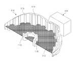
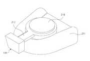
도 1은 본 발명의 제1 실시예에 따른 임플란트용 영상정보 획득장치가 개략적으로 도시된 도면이다.
도 2는 도 1의 인상용 트레이부가 도시된 도면이다.
도 3은 도 2를 다른 방향에서 바라본 도면이다.
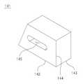
도 4는 도 1의 기준부가 도시된 사시도이다.
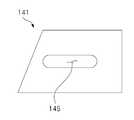
도 5는 도 4의 정면도이다.
도 6는 본 발명의 제2 실시예에 따른 임플란트용 영상정보 획득장치의 인상용 트레이가 도시된 도면이다.
도 7는 도 6을 다른 방향에서 바라본 도면이다.
도 8은 도 6의 하악용 트레이가 도시된 도면이다.
도 9은 도 6의 상악용 트레이가 도시된 도면이다.BRIEF DESCRIPTION OF THE DRAWINGS FIG. 1 is a schematic view showing an image information acquiring apparatus for an implant according to a first embodiment of the present invention; FIG.
Fig. 2 is a view showing the pulling tray of Fig. 1. Fig.
Fig. 3 is a view of Fig. 2 viewed from the other direction. Fig.
4 is a perspective view of the reference portion of FIG.
5 is a front view of Fig.
6 is a view showing an impression tray of an image information acquiring apparatus for implants according to a second embodiment of the present invention.
Fig. 7 is a view of Fig. 6 taken in the other direction.
Fig. 8 is a view showing the mandible tray of Fig. 6; Fig.
Fig. 9 is a view showing the image evacuation tray of Fig. 6; Fig.
본 발명과 본 발명의 동작상의 이점 및 본 발명의 실시에 의하여 달성되는 목적을 충분히 이해하기 위해서는 본 발명의 바람직한 실시 예를 예시하는 첨부 도면 및 첨부 도면에 기재된 내용을 참조하여야만 한다.In order to fully understand the present invention, operational advantages of the present invention, and objects achieved by the practice of the present invention, reference should be made to the accompanying drawings and the accompanying drawings which illustrate preferred embodiments of the present invention.
이하, 첨부된 도면을 참조하여 본 발명의 바람직한 실시 예를 설명함으로써, 본 발명을 상세히 설명한다. 다만, 본 발명을 설명함에 있어서 이미 공지된 기능 혹은 구성에 대한 설명은, 본 발명의 요지를 명료하게 하기 위하여 생략하기로 한다.Hereinafter, the present invention will be described in detail with reference to the preferred embodiments of the present invention with reference to the accompanying drawings. In the following description, well-known functions or constructions are not described in order to avoid unnecessary obscuration of the present invention.
도 1은 본 발명의 제1 실시예에 따른 임플란트용 영상정보 획득장치가 개략적으로 도시된 도면이고, 도 2는 도 1의 인상용 트레이부가 도시된 도면이며, 도 3은 도 2를 다른 방향에서 바라본 도면이고, 도 4는 도 1의 기준부가 도시된 사시도이며, 도 5는 도 4의 정면도이다.FIG. 1 is a view schematically showing an image information acquiring apparatus for an implant according to a first embodiment of the present invention, FIG. 2 is a view showing the pulling tray of FIG. 1, Fig. 4 is a perspective view of the reference portion of Fig. 1, and Fig. 5 is a front view of Fig.
도 1 내지 도 5에 도시된 바와 같이, 본 발명의 실시예에 따른 임플란트용 영상정보 획득장치는, 피시술자(H)의 구강 내에 삽입되어 피시술자(H)의 구강 형상을 획득하는 인상재(미도시)가 수용되는 인상용 트레이부(110)와, 인상용 트레이부(110)가 피시술자(H)의 구강 내에 삽입된 상태에서 피시술자(H)의 구강구조에 대한 제1 영상정보를 획득하는 제1 영상획득부(120)와, 인상재(미도시)에 의해 획득된 피시술자(H)의 구강 형상으로 제작된 구강 모형(M)에 인상용 트레이부(110)가 삽입된 상태에서 구강 모형(M)에 대한 제2 영상정보를 획득하는 제2 영상획득부(130)와, 인상용 트레이부(110)에 결합되며, 제1 영상정보와 제2 영상정보의 매칭 기준이 되도록 제1 영상정보와 제2 영상정보에 표시되는 기준부(140)를 포함한다.1 to 5, an image acquisition device for implants according to an embodiment of the present invention includes an impression material (not shown) that is inserted into the mouth of a subject H and acquires a mouth shape of the person H, A first image acquiring unit that acquires first image information on the oral cavity structure of the subject H in a state where the pulling
인상용 트레이부(110)는 피시술자(H)의 구강 내에 삽입되어 피시술자(H)의 구강 형상을 획득하는 인상재(미도시)를 수용한다.The pulling
이러한 인상용 트레이부(110)는, 제1 측벽부(111)와, 제1 측벽부(111)에 연결되며, 인상재(미도시)를 지지하는 인상재 지지부(112)와, 인상재 지지부(112)와 연결되는 제2 측벽부(113)와, 제1 측벽부(111)에 결합되는 제1 손잡이부(114)를 포함한다.The pulling
제1 측벽부(111)는 피시술자(H)의 치열궁 형상에 적합하게 원호 형상으로 마련되며, 중앙부에서 말단부로 갈수록 높이가 작아지는 형상으로 마련된다.The
또한 제1 측벽부(111)는, 내측면에서 돌출되어 형성되는 복수개의 제1 리브(115)를 포함한다. 이러한 제1 리브(115)는 제1 측벽과 인상재(미도시)의 접촉면적을 넓혀 인상재(미도시)가 인상용 트레이 안정적으로 수용될 수 있도록 한다.The first
인상재 지지부(112)는 제1 측벽부(111)에 연결되며, 인상재(미도시)를 지지한다. 본 실시예에서 인상재 지지부(112)는 부직포 또는 망사로 마련된다.The
제2 측벽부(113)는 인상재 지지부(112)와 연결된다. 이러한 제2 측벽부(113)는 내측면에서 돌출되어 형성되는 복수개의 제2 리브(116)를 포함한다. 이러한 제2 리브(116)는 제2 측벽과 인상재(미도시)의 접촉면적을 넓혀 인상재(미도시)가 인상용 트레이 안정적으로 수용될 수 있도록 한다.The second
제1 손잡이부(114)는 제1 측벽부(111)에 결합되며, 피시술자(H)의 구강내에 인상용 트레이부(110)가 삽입 시 제1 손잡이부(114)가 피시술자(H)의 구강 밖으로 노출될 수 있도록 제1 측벽부(111)에서 돌출되어 마련된다.The first handle 114 is coupled to the
인상재(미도시)는 피시술자(H)의 치열 등에 직접 접촉되어 치열 등의 형상을 체득한다. 이렇게 치열 등의 형상을 체득한 인상재(미도시)에 석고 등을 부어 구강 모형(M)이 제작된다.The impression material (not shown) directly contacts the dentition of the person H to acquire a shape such as dentition. An oral model (M) is produced by pouring gypsum or the like into an impression material (not shown) having a shape such as teeth.
한편, 제1 영상획득부(120)는 인상용 트레이부(110)가 피시술자(H)의 구강 내에 삽입된 상태에서 피시술자(H)의 구강구조에 대한 제1 영상정보를 획득한다. 본 실시예에서 제1 영상획득부(120)는 컴퓨터 단층촬영(computed tomography, CT)이 사용되는데 이에 본 발명의 권리범위가 한정되는 것은 아니며, MRI 등 다양한 방식의 3차원 영상정보 획득장치가 본 실시예의 제1 영상획득부(120)로 사용될 수 있다.The first
본 실시예에서 제1 영상정보는 피시술자(H)의 구강내에 픽스츄어가 식립되는 해부학적 구조물(치조골)에 대한 3차원 영상 정보이며, 이러한 치조골의 3차원 영상정보에 따라 픽스츄어의 식립 위치, 방향, 깊이가 계획된다.In the present embodiment, the first image information is three-dimensional image information about an anatomical structure (alveolar bone) in which a fixture is placed in the mouth of the subject H, and the position, Direction and depth are planned.
제2 영상획득부(130)는 인상재(미도시)에 의해 획득된 피시술자(H)의 구강 형상으로 제작된 구강 모형(M)에 인상용 트레이부(110)가 삽입된 상태에서 구강 모형(M)에 대한 제2 영상정보를 획득한다. 본 실시예에서 제2 영상획득부(130)는 3차원 스캐너가 사용되는데 이에 본 발명의 권리범위가 한정되는 것은 아니며 구강 모형(M)의 3차원 좌표를 획득할 수 있는 다양한 방식의 3차원 영상정보 획득장치가 본 실시예의 제2 영상획득부(130)로 사용될 수 있다.The second
본 실시예에서 제2 영상정보는 피시술자(H)의 치열의 표면형상에 대한 3차원 영상정보이며, 이러한 치열의 표면형상에 대한 3차원 영상정보에 따라 픽스츄어의 식립 위치, 방향, 깊이를 가이드하는 가이드 스텐트(미도시)의 형상 및 구조가 계획된다.In the present embodiment, the second image information is three-dimensional image information on the surface shape of the teeth of the subject H, and the position, orientation, and depth of the fixture are determined based on the three- The shape and structure of the guide stent (not shown) is planned.
기준부(140)는, 인상용 트레이부(110)에 결합되며, 제1 영상정보와 제2 영상정보의 매칭 기준이 되도록 제1 영상정보와 제2 영상정보에 표시된다. 이때 기준부(140)가 제1 영상정보와 제2 영상정보에 명확하게 표시될 수 있도록 기준부(140)는 피시술자(H)의 구강 외부에 배치된다.The
이러한 기준부(140)는 제1 영상획득부(120) 및 제2 영상획득부(130)를 통해 획득된 데이터의 매칭 기준이 된다. 즉 기준부(140)를 기준으로 제1 영상정보와 제2 영상정보를 매칭시킨다.The
본 실시예에서 기준부(140)는 다면체 형상의 기준 블록(141)을 포함한다. 이러한 기준 블록(141)은 제1 모서리(142)와, 제1 모서리(142)에 연결되는 제2 모서리(143)와, 제1 및 제2 모서리(143)에 연결되는 제3 모서리(144)를 포함한다.In this embodiment, the
이러한 제1 모서리(142), 제2 모서리(143) 및 제3 모서리(144)는 상호 수직하게 연결된다. 상호 수직하게 연결된 제1 모서리(142), 제2 모서리(143) 및 제3 모서리(144)는 기준 좌표계의 X축, Y축 및 Z축 방향으로 인식될 수 있어 간편하게 제1 영상획득부(120) 및 제2 영상획득부(130)를 통해 획득된 데이터의 좌표를 매칭시킬 수 있다.The
또한 본 실시예에서 기준 블록(141)은, 단면이 사다리꼴 형상을 갖는 사다리꼴 육면체 형상으로 마련된다. 이러한 사다리꼴 육면체 형상의 기준 블록(141)은 윗면의 길이가 밑면의 길이보다 작아 기준 블록(141)의 상하 구별이 쉬워 제1 영상정보 및 제2 영상정보의 매칭 시 제1 영상정보 및 제2 영상정보의 상하관계를 용이하게 인식할 수 있다.In this embodiment, the
또한 기준 블록(141)의 일측벽에는, 제1 손잡이부(114)의 말단부가 삽입되는 결합홈(145)이 형성된다. 즉 제1 손잡이부(114)의 말단부가 결합홈(145)에 끼워짐으로써 기준 블록(141)이 인상용 트레이부(110)에 결합된다. 또한 기준 블록(141)과 인상용 트레이의 안정적인 결합을 위해 기준 블록(141)과 인상용 트레이를 본딩(bonding)을 통해 결합시킬 수 있다.Further, a
또한 기준 블록(141)은 방사선 불투과성 재질로 마련된다. 이와 같이 기준 블록(141)이 방사선 불투과성 재질로 마련됨으로써, 제1 영상정보 또는 제2 영상정보에 기준 블록(141)이 명확하게 표시될 수 있다.The
기준 블록(141)의 외측벽에는 방사선 불투과성 재질의 코팅막이 마련된다. 이러한 코팅막은 방사선을 불투과시킴으로써, 기준 블록(141)이 제1 영상정보 또는 제2 영상정보에 명확하게 표시될 수 있다. A coating film of a radiopaque material is provided on the outer wall of the
이러한 구성을 갖는 본 발명의 제1 실시예에 따른 임플란트용 영상정보 획득장치의 동작에 대하여 설명하기로 한다.The operation of the image information acquiring apparatus for implant according to the first embodiment of the present invention having such a configuration will be described.
인상재(미도시)가 수용된 인상용 트레이부(110)를 피시술자(H)의 구강 내에 삽입한 후 피시술자(H)가 인상재(미도시)를 깨물은 상태에서 제1 영상획득부(120)가 피시술자(H)의 구강구조에 대한 제1 영상정보를 획득한다.The first
이후 인상재(미도시)에 의해 획득된 피시술자(H)의 구강 형상으로 제작된 구강 모형(M)에 앞서 사용된 피시술자(H)에 사용된 인상용 트레이를 다시 구강 모형(M)에 삽입시킨 후 제2 영상획득부(130)를 통해 제2 영상정보를 획득한다.The tracing tray used in the subject H previously used for the oral cavity model M of the patient H obtained by the impression material (not shown) is inserted into the oral cavity model M again And acquires the second image information through the second
앞서 설명한 픽스츄어의 식립 위치, 방향, 깊이를 가이드 하는 가이드 스텐트는 CAD/CAM을 통해 제작되는데, CAD/CAM 작업을 위해 제1 영상정보의 좌표와 제2 영상정보의 좌표를 기준 블록(141)을 기준으로 하여 일치시킨다.The guide stent for guiding the placement position, direction, and depth of the fixture described above is manufactured through CAD / CAM. In order to perform the CAD / CAM operation, the coordinates of the first image information and the coordinates of the second image information are stored in the
즉 제1 영상정보에 표시된 기준 블록(141)과 제2 영상정보에 표시된 기준 블록(141)의 좌표를 일치시킴에 따라 간편하게 제1 영상정보와 제2 영상정보를 매칭시킬 수 있다.That is, the first image information and the second image information can be easily matched by matching the coordinates of the
따라서 제1 영상정보로부터 획득된 피시술자(H)의 구강부위에 대한 해부학적 영상정보에서 계획한 픽스츄어의 위치, 방향, 깊이에 대한 3차원 수치정보와 제2 영상정보로부터 획득된 구강 모형(M)의 3차원 수치정보를 기준 블록(141)을 기준으로 하여 좌표 변환을 실시하면 결과적으로 해부학적 영상정보와 피시술자(H)의 치열의 표면형상을 간편하게 정합할 수 있고, 그에 따라 계획한 픽스츄어의 위치, 방향, 깊이에 대한 3차원적 수치정보에 따라 빠르고 간편하게 피시술자(H)에 적합한 가이드 스텐트를 제작할 수 있다.Therefore, in the anatomical image information of the oral part of the subject H, which is obtained from the first image information, three-dimensional numerical information about the position, direction and depth of the planned fixture and the oral model M Dimensional coordinate information on the
이와 같이 본 발명에 따른 임플란트용 영상정보 획득장치는 피시술자(H)의 해부학적 정보를 포함하는 제1 영상정보와 피시술자(H)의 구강내 조직을 본뜬 구강모형 3차원스캐닝 하여 얻은 제2 영상정보의 매칭을 제1 영상정보 및 제2 영상정보에 표시되는 기준부(140)를 기준으로 하여 수행함으로써, 제1 영상정보 및 제2 영상정보의 매칭시간을 단축할 수 있고, 그에 따라 치과용 임플란트의 시술시간을 단축시켜 원-데이(one day) 임플란트 시술을 가능하게 한다.As described above, the apparatus for acquiring image information for an implant according to the present invention includes first image information including anatomical information of a subject H, second image information obtained by three-dimensional scanning of an oral cavity model of a subject H, The matching time of the first image information and the second image information can be shortened by performing the matching of the first image information and the second image information with reference to the
피시술자의 해부학적 정보를 포함하는 제1 영상정보와 피시술자의 구강내 조직을 본뜬 구강모형 3차원스캐닝 하여 얻은 제2 영상정보의 매칭을 제1 영상정보 및 제2 영상정보에 표시되는 기준부를 기준으로 하여 수행함으로써, 정밀한 가이드 스텐트의 제작이 가능하고 치과용 임플란트의 시술시간을 단축시켜 원-데이(one day) 임플란트 시술을 가능하게 한다.The matching between the first image information including the anatomical information of the subject and the second image information obtained by scanning the mouth model three-dimensionally based on the intraoral structure of the subject is compared with the reference portion displayed in the first image information and the second image information Thereby making it possible to produce a precise guide stent and shorten the procedure time of the dental implant, thereby enabling a one-day implant procedure.
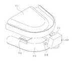
도 6는 본 발명의 제2 실시예에 따른 임플란트용 영상정보 획득장치의 인상용 트레이가 도시된 도면이고, 도 7는 도 6을 다른 방향에서 바라본 도면이며, 도 8은 도 6의 하악용 트레이가 도시된 도면이고, 도 9은 도 6의 상악용 트레이가 도시된 도면이다.6 is a view showing a tray for pulling up an image information acquiring apparatus for implants according to a second embodiment of the present invention, FIG. 7 is a view of FIG. 6 viewed from another direction, FIG. 8 is a cross- And Fig. 9 is a view showing the image evacuation tray of Fig.
본 실시예에 따른 인상용 트레이부(210)는 주로 무치아 환자나 치아 결손이 많은 피시술자(H)에 사용된다.The pulling tray 210 according to the present embodiment is mainly used for a non-teeth patient or a dentist H who has many tooth defects.
본 실시예에서 인상용 트레이부(210)는, 상악용 트레이(211)와, 상악용 트레이(211)에 결합되는 제2 손잡이부(212)와, 상악용 트레이(211)의 하측에 배치되는 하악용 트레이(213)와, 하악용 트레이(213)에 결합되는 제3 손잡이(214)와, 상악용 트레이(211) 및 하악용 트레이(213)에 연결되어 상악용 트레이(211)와 하악용 트레이(213) 사이의 간격을 조절하는 간격 조절부(215)를 포함한다.In this embodiment, the pulling tray unit 210 includes a
기준 블록(141)의 결합홈(145)에는 제2 손잡이부(212) 또는 제3 손잡이부(214)의 말단부가 끼워짐으로써 기준 블록(141)이 상악용 트레이(211) 또는 하악용 트레이(213)와 결합된다.The distal end of the
본 실시예에서 간격 조절부(215)는, 하악용 트레이(213)에 결합되는 지지판(216)과, 지지판(216)에 업/다운(up/down) 가능하게 결합되는 업/다운(up/down) 이동부(217)와, 상악용 트레이(211)에 결합되며, 업/다운(up/down) 이동부(217)에 접촉되는 접촉판(218)을 포함한다.In this embodiment, the
업/다운(up/down) 이동부(217)는, 지지판(216)에 지지판(216)에 치합되는 이동나사(219)와, 이동나사(219)의 말단부에 마련되는 접촉핀(R)을 포함한다.The up / down moving
이동나사(219)에 대한 조작의 편의를 위해 이동나사(219)에 핸들(N)이 결합된다.The handle N is coupled to the moving
이와 같이 본 실시예에 따른 인상용 트레이부(210)는 간격 조절부(215)가 상악용 트레이(211)와 하악용 트레이(213) 사이의 간격을 조절함으로써, 무치아 환자나 치아 결손이 많은 피시술의 구강내에 인상용 트레이부(210)를 삽입한 상태에서의 상악용 트레이(211)와 하악용 트레이(213) 사이의 간격과 피시술자(H)의 구강 모형(M)에 삽입된 상태에서의 상악용 트레이(211)와 하악용 트레이(213) 사이의 간격을 동일하게 할 수 있어 제1 영상정보와 제2 영상정보를 간편하게 매칭시킬 수 있는 장점이 있다.As described above, the pulling tray unit 210 according to the present embodiment is configured such that the
이상 도면을 참조하여 본 실시예에 대해 상세히 설명하였지만 본 실시예의 권리범위가 전술한 도면 및 설명에 국한되지는 않는다.Although the present invention has been described in detail with reference to the above drawings, the scope of the scope of the present invention is not limited to the above-described drawings and description.
이와 같이 본 발명은 기재된 실시예에 한정되는 것이 아니고, 본 발명의 사상 및 범위를 벗어나지 않고 다양하게 수정 및 변형할 수 있음은 이 기술의 분야에서 통상의 지식을 가진 자에게 자명하다. 따라서 그러한 수정예 또는 변형예들은 본 발명의 특허청구범위에 속한다 하여야 할 것이다.It will be apparent to those skilled in the art that various modifications and variations can be made in the present invention without departing from the spirit or scope of the invention. Accordingly, such modifications or variations are intended to fall within the scope of the appended claims.
110,210: 인상용 트레이부111: 제1 측벽부
112: 인상재 지지부113: 제2 측벽부
114: 제1 손잡이부 115: 제1 리브
116: 제2 리브120: 제1 영상획득부
130: 제2 영상획득부140: 기준부
141: 기준 블록142: 제1 모서리
143: 제2 모서리144: 제3 모서리
145: 결합홈 211: 상악용 트레이
212: 제2 손잡이부 213: 하악용 트레이
214: 제3 손잡이부 215: 간격 조절부
216: 지지판 217: 업/다운(up/down) 이동부
218: 접촉판 219: 이동나사
H: 피시술자 N: 핸들
M: 구강 모형110, 210: lifting tray part 111: first side wall part
112: impression material supporting portion 113: second side wall portion
114: first handle 115: first rib
116: second rib 120: first image acquiring unit
130: second image acquisition unit 140:
141: Reference block 142: First corner
143: second corner 144: third corner
145: coupling groove 211:
212: second handle portion 213: lower tray
214: Third handle 215:
216: support plate 217: up / down moving part
218: contact plate 219: moving screw
H: Physician N: Handle
M: Oral model
Claims (18)
Translated fromKorean상기 인상용 트레이부가 상기 피시술자의 구강 내에 삽입된 상태에서 상기 피시술자의 구강구조에 대한 제1 영상정보를 획득하는 제1 영상획득부;
상기 인상재에 의해 획득된 상기 피시술자의 구강 형상으로 제작된 구강 모형에 상기 인상용 트레이부가 삽입된 상태에서 상기 구강 모형에 대한 제2 영상정보를 획득하는 제2 영상획득부; 및
상기 인상용 트레이부에 결합되며, 상기 제1 영상정보와 상기 제2 영상정보의 매칭 기준이 되도록 상기 제1 영상정보와 상기 제2 영상정보에 표시되는 기준부를 포함하며,
상기 인상용 트레이부는,
제1 측벽부;
상기 제1 측벽부에 연결되며, 상기 인상재를 지지하는 인상재 지지부;
상기 인상재 지지부와 연결되는 제2 측벽부; 및
상기 제1 측벽부에 결합되는 제1 손잡이부를 포함하는 임플란트용 영상정보 획득장치.An impression tray portion which is inserted into the mouth of the subject and receives an impression material for acquiring a mouth shape of the subject;
A first image acquiring unit acquiring first image information on the oral cavity structure of the subject while the lifting tray is inserted into the mouth of the subject;
A second image acquiring unit for acquiring second image information of the oral cavity model in a state where the pull-up tray is inserted into the oral cavity model of the subject who is acquired by the impression material; And
And a reference unit coupled to the pull-up tray unit and being displayed on the first image information and the second image information so as to be a matching reference of the first image information and the second image information,
The lifting tray unit includes:
A first side wall portion;
An impression material support portion connected to the first side wall portion and supporting the impression material;
A second sidewall portion connected to the impression material support portion; And
And a first grip portion coupled to the first side wall portion.
상기 기준부는 상기 피시술자의 구강 외부에 배치되는 것을 특징으로 하는 임플란트용 영상정보 획득장치.The method according to claim 1,
Wherein the reference portion is disposed outside the oral cavity of the subject.
상기 기준부는 다면체 형상의 기준 블록을 포함하는 임플란트용 영상정보 획득장치.The method according to claim 1,
Wherein the reference portion includes a polygonal reference block.
상기 기준 블록은,
제1 모서리;
상기 제1 모서리에 연결되는 제2 모서리; 및
상기 제1 및 제2 모서리에 연결되는 제3 모서리를 포함하는 임플란트용 영상정보 획득장치.The method of claim 3,
The reference block includes:
A first edge;
A second edge coupled to the first edge; And
And a third edge connected to the first and second edges.
상기 제1 모서리, 제2 모서리 및 제3 모서리는 상호 수직하게 연결되는 것을 특징으로 하는 임플란트용 영상정보 획득장치.5. The method of claim 4,
Wherein the first edge, the second edge, and the third edge are vertically connected to each other.
상기 기준 블록은, 단면이 사다리꼴 형상을 갖는 사다리꼴 육면체 형상으로 마련되는 것을 특징으로 하는 임플란트용 영상정보 획득장치.The method of claim 3,
Wherein the reference block is provided in a trapezoidal hexahedron shape having a trapezoidal cross section.
상기 기준 블록의 일측벽에는, 상기 인상용 트레이부의 일부가 삽입되는 결합홈이 형성되는 임플란트용 영상정보 획득장치.The method according to claim 6,
And an engaging groove into which a part of the pulling tray is inserted is formed on one side wall of the reference block.
상기 기준 블록은 방사선 불투과성 재질로 마련되는 것을 특징으로 하는 임플란트용 영상정보 획득장치.The method of claim 3,
Wherein the reference block is made of a radiopaque material.
상기 기준 블록의 외측벽에는 방사선 불투과성 재질의 코팅막이 마련되는 것을 특징으로 하는 임플란트용 영상정보 획득장치.The method of claim 3,
Wherein a coating film of a radiopaque material is provided on an outer wall of the reference block.
상기 기준부는 단면이 사다리꼴 형상을 갖는 사다리꼴 육면체 형상으로 마련되며,
상기 기준부의 일측벽에는, 상기 제1 손잡이부의 말단부가 삽입되는 결합홈이 형성되는 임플란트용 영상정보 획득장치.The method according to claim 1,
The reference portion is provided in a trapezoidal hexahedron shape having a trapezoidal cross section,
And an engaging groove into which the distal end of the first handle is inserted is formed on one side wall of the reference portion.
상기 제1 측벽부는, 내측면에서 돌출되어 형성되는 복수개의 제1 리브를 포함하는 임플란트용 영상정보 획득장치.The method according to claim 1,
Wherein the first sidewall portion includes a plurality of first ribs protruding from an inner surface thereof.
상기 제2 측벽부는, 내측면에서 돌출되어 형성되는 복수개의 제2 리브를 포함하는 임플란트용 영상정보 획득장치.The method according to claim 1,
Wherein the second side wall portion includes a plurality of second ribs protruding from the inner side.
상기 인상재 지지부는, 부직포 또는 망사로 마련되는 것을 특징으로 하는 임플란트용 영상정보 획득장치.The method according to claim 1,
Wherein the impression material supporting portion is formed of a nonwoven fabric or a mesh.
상기 인상용 트레이부가 상기 피시술자의 구강 내에 삽입된 상태에서 상기 피시술자의 구강구조에 대한 제1 영상정보를 획득하는 제1 영상획득부;
상기 인상재에 의해 획득된 상기 피시술자의 구강 형상으로 제작된 구강 모형에 상기 인상용 트레이부가 삽입된 상태에서 상기 구강 모형에 대한 제2 영상정보를 획득하는 제2 영상획득부; 및
상기 인상용 트레이부에 결합되며, 상기 제1 영상정보와 상기 제2 영상정보의 매칭 기준이 되도록 상기 제1 영상정보와 상기 제2 영상정보에 표시되는 기준부를 포함하며,
상기 인상용 트레이부는,
상악용 트레이;
상기 상악용 트레이에 결합되는 제2 손잡이부;
상기 상악용 트레이의 하측에 배치되는 하악용 트레이;
상기 하악용 트레이에 결합되는 제3 손잡이부; 및
상기 상악용 트레이 및 하악용 트레이 중 어느 하나에 마련되며, 다른 하나에 연결되어 상기 상악용 트레이와 상기 하악용 트레이 사이의 간격을 조절하는 간격 조절부를 포함하는 임플란트용 영상정보 획득장치.An impression tray portion which is inserted into the mouth of the subject and receives an impression material for acquiring a mouth shape of the subject;
A first image acquiring unit acquiring first image information on the oral cavity structure of the subject while the lifting tray is inserted into the mouth of the subject;
A second image acquiring unit for acquiring second image information of the oral cavity model in a state where the pull-up tray is inserted into the oral cavity model of the subject who is acquired by the impression material; And
And a reference unit coupled to the pull-up tray unit and being displayed on the first image information and the second image information so as to be a matching reference of the first image information and the second image information,
The lifting tray unit includes:
An abuse tray;
A second handle coupled to the topographic tray;
A lower tray disposed below the upper deformation tray;
A third handle coupled to the mandible tray; And
And an interval adjusting unit that is provided at any one of the upper and lower tray and the lower tray and is connected to the other to adjust the interval between the upper and lower tails and the lower tray.
상기 간격 조절부는,
상기 하악용 트레이에 결합되는 지지판;
상기 지지판에 업/다운(up/down) 가능하게 결합되는 업/다운(up/down) 이동부; 및
상기 상악용 트레이에 결합되며, 상기 업/다운(up/down) 이동부에 접촉되는 접촉판을 포함하는 임플란트용 영상정보 획득장치.16. The method of claim 15,
Wherein the interval adjusting unit comprises:
A support plate coupled to the mandible tray;
An up / down moving unit coupled to the support plate so as to be able to up / down; And
And a contact plate coupled to the upper deformation tray and contacting the up / down moving unit.
상기 업/다운(up/down) 이동부는,
상기 지지판에 지지판에 치합되는 이동나사; 및
상기 이동나사의 말단부에 마련되는 접촉핀을 포함하는 임플란트용 영상정보 획득장치.17. The method of claim 16,
The up / down moving unit includes:
A moving screw engaged with the support plate on the support plate; And
And a contact pin provided at a distal end of the moving screw.
상기 기준부는 단면이 사다리꼴 형상을 갖는 사다리꼴 육면체 형상으로 마련되며,
상기 기준부의 일측벽에는, 상기 제2 손잡이부 또는 제3 손잡이부의 말단부가 삽입되는 결합홈이 형성되는 임플란트용 영상정보 획득장치.17. The method of claim 16,
The reference portion is provided in a trapezoidal hexahedron shape having a trapezoidal cross section,
And an engaging groove into which the distal end of the second handle or the third handle is inserted is formed in one side wall of the reference portion.
Priority Applications (1)
| Application Number | Priority Date | Filing Date | Title |
|---|---|---|---|
| KR20130049006AKR101491704B1 (en) | 2013-05-01 | 2013-05-01 | Apparatus for acquiring image information using implant |
Applications Claiming Priority (1)
| Application Number | Priority Date | Filing Date | Title |
|---|---|---|---|
| KR20130049006AKR101491704B1 (en) | 2013-05-01 | 2013-05-01 | Apparatus for acquiring image information using implant |
Publications (2)
| Publication Number | Publication Date |
|---|---|
| KR20140130582A KR20140130582A (en) | 2014-11-11 |
| KR101491704B1true KR101491704B1 (en) | 2015-02-16 |
Family
ID=52452363
Family Applications (1)
| Application Number | Title | Priority Date | Filing Date |
|---|---|---|---|
| KR20130049006AActiveKR101491704B1 (en) | 2013-05-01 | 2013-05-01 | Apparatus for acquiring image information using implant |
Country Status (1)
| Country | Link |
|---|---|
| KR (1) | KR101491704B1 (en) |
Cited By (4)
| Publication number | Priority date | Publication date | Assignee | Title |
|---|---|---|---|---|
| KR20170091847A (en)* | 2016-02-02 | 2017-08-10 | 김도현 | Method for Guiding Dental Implant Surgery |
| WO2018143497A1 (en)* | 2017-02-03 | 2018-08-09 | 김도현 | Implant surgery guiding method |
| KR101918936B1 (en)* | 2017-06-16 | 2018-11-15 | 김종철 | Tray-guide and Tray-guide manufacturing system |
| KR20210092997A (en) | 2020-01-17 | 2021-07-27 | 계명대학교 산학협력단 | Smart Glass for Dental Implants Surgical |
Families Citing this family (3)
| Publication number | Priority date | Publication date | Assignee | Title |
|---|---|---|---|---|
| ITUA20162112A1 (en)* | 2016-03-30 | 2017-09-30 | Lynx S R L | Apparatus and method for the correct positioning of dental implants. |
| KR101735783B1 (en)* | 2017-03-02 | 2017-05-15 | 주식회사 쓰리디산업영상 | System and method for examining a drilling template |
| KR102061644B1 (en)* | 2017-12-19 | 2020-02-11 | 주식회사 키스톤 | Image Generation System for implant Diagnosis and image Generation methode the same |
Citations (4)
| Publication number | Priority date | Publication date | Assignee | Title |
|---|---|---|---|---|
| US20080199827A1 (en) | 2005-09-07 | 2008-08-21 | Lukas Kamer | Method for Producing a Guiding Member for Guiding a Surgical Tool, and Guiding Member Produced According to This Method |
| KR20090077967A (en)* | 2006-10-27 | 2009-07-16 | 노벨 바이오케어 서비시스 아게 | Dental impression tray to use for impression acquisition of dental structure |
| KR20100117385A (en)* | 2009-04-24 | 2010-11-03 | 이태경 | Method of image- matching for implant using tray with marker |
| KR20120009478A (en)* | 2009-05-19 | 2012-02-01 | 김태형 | Denture making method and apparatus |
- 2013
- 2013-05-01KRKR20130049006Apatent/KR101491704B1/enactiveActive
Patent Citations (4)
| Publication number | Priority date | Publication date | Assignee | Title |
|---|---|---|---|---|
| US20080199827A1 (en) | 2005-09-07 | 2008-08-21 | Lukas Kamer | Method for Producing a Guiding Member for Guiding a Surgical Tool, and Guiding Member Produced According to This Method |
| KR20090077967A (en)* | 2006-10-27 | 2009-07-16 | 노벨 바이오케어 서비시스 아게 | Dental impression tray to use for impression acquisition of dental structure |
| KR20100117385A (en)* | 2009-04-24 | 2010-11-03 | 이태경 | Method of image- matching for implant using tray with marker |
| KR20120009478A (en)* | 2009-05-19 | 2012-02-01 | 김태형 | Denture making method and apparatus |
Cited By (6)
| Publication number | Priority date | Publication date | Assignee | Title |
|---|---|---|---|---|
| KR20170091847A (en)* | 2016-02-02 | 2017-08-10 | 김도현 | Method for Guiding Dental Implant Surgery |
| KR102330616B1 (en)* | 2016-02-02 | 2021-11-24 | 김도현 | Method for Guiding Dental Implant Surgery |
| WO2018143497A1 (en)* | 2017-02-03 | 2018-08-09 | 김도현 | Implant surgery guiding method |
| US11229503B2 (en) | 2017-02-03 | 2022-01-25 | Do Hyun Kim | Implant surgery guiding method |
| KR101918936B1 (en)* | 2017-06-16 | 2018-11-15 | 김종철 | Tray-guide and Tray-guide manufacturing system |
| KR20210092997A (en) | 2020-01-17 | 2021-07-27 | 계명대학교 산학협력단 | Smart Glass for Dental Implants Surgical |
Also Published As
| Publication number | Publication date |
|---|---|
| KR20140130582A (en) | 2014-11-11 |
Similar Documents
| Publication | Publication Date | Title |
|---|---|---|
| KR101491704B1 (en) | Apparatus for acquiring image information using implant | |
| KR101273386B1 (en) | Intraoral marker for the synchronization of three dimensional image data | |
| KR102114015B1 (en) | Virtually designing a customized healing abutment | |
| KR101554157B1 (en) | reference marker for attaching intraoral and manufacturing method for guide stent of dental implant operation using the same | |
| US8682043B2 (en) | Method of merging anatomical data and surface data of a patient's dentition | |
| ES2739460T3 (en) | Repositioning of components related to cranial surgical procedures in a patient | |
| KR101608017B1 (en) | method for manufacturing surgical guide using reference marker attached in mouth for dental implant of edentulous patient | |
| EP2254068B1 (en) | Method and system providing improved data matching for virtual planning | |
| KR101631258B1 (en) | manufacturing method for 3D oral confirm model using digital scan body | |
| KR102246985B1 (en) | dental implant insertion set | |
| JP2019528938A5 (en) | ||
| JP2015527129A (en) | Method and device for adjusting the attachment of a dental implant | |
| KR101918936B1 (en) | Tray-guide and Tray-guide manufacturing system | |
| KR101953692B1 (en) | Device and method for processing image for generating design image based on reference marker | |
| US12274590B2 (en) | Method for providing a dental prosthesis and a positioning guide for placing the dental prosthesis | |
| CN111789688B (en) | Customizable dental appliance | |
| KR20190013216A (en) | Method for manufacturing complete denture for edentulous patients | |
| KR101550369B1 (en) | method for manufacturing surgical guide and crown, abutment in mouth for dental implant | |
| KR102215068B1 (en) | Apparatus and Method for Registrating Implant Diagnosis Image | |
| KR101291754B1 (en) | Implant parallel procedure device and method | |
| KR101554158B1 (en) | method for manufacturing surgical guide of dental implant using cloud system | |
| KR20110074186A (en) | How to design a prosthesis | |
| KR101675503B1 (en) | reference wire attached in mouth and method for manufacturing surgical guide and crown, abutment using thereof for dental implant | |
| KR102082917B1 (en) | Dental implant procedure guide device, dental implant procedure guide device manufacturing system and methode the same | |
| KR101452718B1 (en) | bite tray for image matching |
Legal Events
| Date | Code | Title | Description |
|---|---|---|---|
| A201 | Request for examination | ||
| PA0109 | Patent application | St.27 status event code:A-0-1-A10-A12-nap-PA0109 | |
| PA0201 | Request for examination | St.27 status event code:A-1-2-D10-D11-exm-PA0201 | |
| PN2301 | Change of applicant | St.27 status event code:A-3-3-R10-R13-asn-PN2301 St.27 status event code:A-3-3-R10-R11-asn-PN2301 | |
| D13-X000 | Search requested | St.27 status event code:A-1-2-D10-D13-srh-X000 | |
| D14-X000 | Search report completed | St.27 status event code:A-1-2-D10-D14-srh-X000 | |
| E902 | Notification of reason for refusal | ||
| PE0902 | Notice of grounds for rejection | St.27 status event code:A-1-2-D10-D21-exm-PE0902 | |
| E13-X000 | Pre-grant limitation requested | St.27 status event code:A-2-3-E10-E13-lim-X000 | |
| P11-X000 | Amendment of application requested | St.27 status event code:A-2-2-P10-P11-nap-X000 | |
| P13-X000 | Application amended | St.27 status event code:A-2-2-P10-P13-nap-X000 | |
| E701 | Decision to grant or registration of patent right | ||
| PE0701 | Decision of registration | St.27 status event code:A-1-2-D10-D22-exm-PE0701 | |
| PG1501 | Laying open of application | St.27 status event code:A-1-1-Q10-Q12-nap-PG1501 | |
| PR0701 | Registration of establishment | St.27 status event code:A-2-4-F10-F11-exm-PR0701 | |
| PR1002 | Payment of registration fee | St.27 status event code:A-2-2-U10-U11-oth-PR1002 Fee payment year number:1 | |
| PG1601 | Publication of registration | St.27 status event code:A-4-4-Q10-Q13-nap-PG1601 | |
| P22-X000 | Classification modified | St.27 status event code:A-4-4-P10-P22-nap-X000 | |
| FPAY | Annual fee payment | Payment date:20180205 Year of fee payment:4 | |
| PR1001 | Payment of annual fee | St.27 status event code:A-4-4-U10-U11-oth-PR1001 Fee payment year number:4 | |
| R18-X000 | Changes to party contact information recorded | St.27 status event code:A-5-5-R10-R18-oth-X000 | |
| FPAY | Annual fee payment | Payment date:20190207 Year of fee payment:5 | |
| PR1001 | Payment of annual fee | St.27 status event code:A-4-4-U10-U11-oth-PR1001 Fee payment year number:5 | |
| FPAY | Annual fee payment | Payment date:20200203 Year of fee payment:6 | |
| PR1001 | Payment of annual fee | St.27 status event code:A-4-4-U10-U11-oth-PR1001 Fee payment year number:6 | |
| PR1001 | Payment of annual fee | St.27 status event code:A-4-4-U10-U11-oth-PR1001 Fee payment year number:7 | |
| PR1001 | Payment of annual fee | St.27 status event code:A-4-4-U10-U11-oth-PR1001 Fee payment year number:8 | |
| PR1001 | Payment of annual fee | St.27 status event code:A-4-4-U10-U11-oth-PR1001 Fee payment year number:9 | |
| P22-X000 | Classification modified | St.27 status event code:A-4-4-P10-P22-nap-X000 | |
| PR1001 | Payment of annual fee | St.27 status event code:A-4-4-U10-U11-oth-PR1001 Fee payment year number:10 | |
| PR1001 | Payment of annual fee | St.27 status event code:A-4-4-U10-U11-oth-PR1001 Fee payment year number:11 | |
| PN2301 | Change of applicant | St.27 status event code:A-5-5-R10-R13-asn-PN2301 St.27 status event code:A-5-5-R10-R11-asn-PN2301 |